

Page 1
FFD MANUAL
FILTER FAILURE
DETECTOR
PENTAIR CLEAN AIR SYSTEMS
INSTALLATION AND OPERATION MANUAL – OWNER'S RECORD
iINSTALLATION AND OPERATION MANUAL – OWNER'S RECORD FFD MANUAL – FILTER FAILURE DETECTOR
Page 2

FFD MANUAL
FILTER FAILURE DETECTOR
Installation and Operation Manual – Owner's Record
TABLE OF CONTENTS
1 INTRODUCTION .................................................................................................................................................................. 1
Purpose of this Manual ................................................................................................................................................................ 1
Product Safety
Danger from Process
Safety Procedures
Limits of Use.................................................................................................................................................................................
Additional Information
List of Abbreviations
Product Parts and Options
2 CERTIFICATION ................................................................................................................................................................... 3
Conformance and related Standards .......................................................................................................................................... 3
ATEX Standards
3 PRODUCT DESCRIPTION .................................................................................................................................................... 4
3.1 Components – Sensor Variants .......................................................................................................................................... 4
3.2 Overview ............................................................................................................................................................................... 4
3.3 Sensor .................................................................................................................................................................................. 5
3.4 Principle of Operation ......................................................................................................................................................... 5
4 SENSOR SAFETY DESCRIPTION ......................................................................................................................................... 6
4.1 Hazardous Areas ................................................................................................................................................................. 6
4.1.1 Hazardous Zone Classification ................................................................................................................................ 6
4.2 CENELEC Codes .................................................................................................................................................................. 6
4.2.1 Gas Atmospheres ..................................................................................................................................................... 6
4.2.2 Dust Atmospheres .................................................................................................................................................... 6
4.3 Special Conditions of Safe Use for Sensor Enclosure ...................................................................................................... 6
4.4 Special Conditions of Safe Use for Sensor Body & Probe ................................................................................................ 7
4.5 Equipment Marking Information ........................................................................................................................................ 7
5 Sensor Installation ............................................................................................................................................................. 8
5.1 Safety Information ............................................................................................................................................................... 8
5.2 Prerequisites and Guidelines .............................................................................................................................................. 8
5.2.1 Choosing the Best Position for the Sensor ............................................................................................................. 8
.............................................................................................................................................................................. 1
.......................................................................................................................................................... 1
........................................................................................................................................................................ 1
2
................................................................................................................................................................. 2
............................................................................................................................................................ 2
.................................................................................................................................................. 2
................................................................................................................................................................... 3
ii INSTALLATION AND OPERATION MANUAL – OWNER'S RECORD FFD MANUAL – FILTER FAILURE DETECTOR
Page 3

5.2.2 Location Requirements ............................................................................................................................................ 8
5.2.3 Cabling Guidelines ................................................................................................................................................... 8
5.2.4 Grounding the Sensor .............................................................................................................................................. 9
5.2.5 Running Cables between Sensor and Power Supply ............................................................................................. 9
5.3 Mounting the Sensor ........................................................................................................................................................... 10
5.3.1 Safety Information .................................................................................................................................................... 10
5.3.2 Fitting the Sensor to the Stack ................................................................................................................................ 10
5.4 Connecting the Sensor ........................................................................................................................................................ 11
5.4.1 Safety Information .................................................................................................................................................... 11
5.4.2 Sensor Connections ................................................................................................................................................. 11
5.4.3 Relay Outputs ........................................................................................................................................................... 12
5.4.4 4–20 mA Output ........................................................................................................................................................ 12
5.4.5 Connecting the Power Supply .................................................................................................................................. 13
6 Setting up the FFD .............................................................................................................................................................. 14
6.1 Safety Information ............................................................................................................................................................... 14
6.2 Control Panel Overview ....................................................................................................................................................... 14
6.3 Setup Procedure .................................................................................................................................................................. 15
6.3.1 Changing the Sensor Sensitivity .............................................................................................................................. 18
7 Operation ............................................................................................................................................................................ 20
7.1 General Operation ............................................................................................................................................................... 20
7.2 Alarm Operation .................................................................................................................................................................. 20
8 Maintenance ....................................................................................................................................................................... 21
8.1 Safety Information ............................................................................................................................................................... 21
8.2 Preventative Maintenance Programme ............................................................................................................................. 21
8.3 Sensor Handling in Hazardous Areas ................................................................................................................................ 22
8.3.1 Removing the Sensor from the Stack ..................................................................................................................... 22
8.3.2 Opening the Sensor Enclosure in a Hazardous Area ............................................................................................. 22
8.4 Cleaning the Sensor ............................................................................................................................................................ 22
8.5 Troubleshooting ................................................................................................................................................................... 23
8.5.1 General ...................................................................................................................................................................... 23
8.5.2 Alarms ....................................................................................................................................................................... 23
9 Technical Data .................................................................................................................................................................... 24
9.1 Process and Application Conditions ................................................................................................................................... 24
9.1.1 User Controls and Functions ................................................................................................................................... 24
9.2 Sensor Specification ............................................................................................................................................................ 24
9.2.1 Dimensioned Drawing – Sensor .............................................................................................................................. 25
9.3 Sensor Options .................................................................................................................................................................... 25
9.4 Cabling ................................................................................................................................................................................. 25
iiiINSTALLATION AND OPERATION MANUAL – OWNER'S RECORD FFD MANUAL – FILTER FAILURE DETECTOR
Page 4

GENERAL NOTICES ..................................................................................................................................................................... 26
Compliance ................................................................................................................................................................................... 26
Waste of Electrical and Electronic Equipment (WEEE) Directive (2012/19/EU)
RoHS Compliance Statement
List of Materials (ISO 14001)
............................................................................................................................................. 26
............................................................................................................................................... 26
............................................................... 26
LIST OF FIGURES
Figure 1: FFD sensor
Figure 2: Fitting the sensor to the stack
Figure 3: Sensor PCB connections
Figure 4: Connecting the sensor relays
................................................................................................................................................................... 4
..................................................................................................................................... 10
............................................................................................................................................. 11
...................................................................................................................................... 12
Figure 5: Connecting the 4–20 mA output .................................................................................................................................. 12
Figure 6: Connecting the sensor power supply
Figure 7: FFD control panel overview
Figure 8: Setup procedure – Step 1
Figure 9: Setup procedure – Step 2
......................................................................................................................................... 14
............................................................................................................................................. 15
............................................................................................................................................. 16
Figure 10: Setup procedure – Step 3 Calibrate the unit
Figure 11: Setup procedure – Step 3 Reset MODE slide switch
Figure 12: Setup procedure – Step 4
Figure 13: Setup procedure – Step 5
Figure 14: Changing sensor sensitivity
........................................................................................................................................... 17
........................................................................................................................................... 18
....................................................................................................................................... 18
.......................................................................................................................... 13
............................................................................................................ 16
............................................................................................... 17
© Copyright by Pentair International Ltd. 2019
This manual is provided as an aid to owners of a Pentair Environmental Systems instrument and contains information proprietary to Pentair Environmental Systems.
This manual may not, in whole or part, be copied, or reproduced without the express written consent of Pentair Environmental Systems.
Goyen Controls Co Pty Ltd reserve the right to change product designs and specifications without notice.
Issue 01 – May 2019
iv INSTALLATION AND OPERATION MANUAL – OWNER'S RECORD FFD MANUAL – FILTER FAILURE DETECTOR
Page 5
1 INTRODUCTION
PURPOSE OF THIS MANUAL
This manual contains all information necessary for the correct installation, setup, operation, and maintenance of the
instrument(s). The procedures given in this manual must be carried out only by suitably trained and qualified personnel.
PRODUCT SAFETY
The following symbols are used throughout this manual to indicate procedures that, if not followed correctly, may result in
personal injury or damage to the equipment.
WARNING!
Warnings alert the user to a procedure or practice which, if not followed correctly, can result in personal injury
or injury of others.
CAUTION!
Cautions alert the user to a procedure or practice which, if not followed correctly, can result in damage to the system
or ancillary equipment.
NOTES are used to highlight important information that assists the user in carrying out a procedure or in understanding the text.
Danger from Process
It is possible that the sensor is installed in ducting that contains process particulate (and other flue gas constituents) hazardous
to health. This may take one or more of the following forms:
•Particulate which is flammable or explosive;
•Particulate which is toxic or in some other way hazardous to health;
•Particulate contained within high-temperature gas.
Take Precautionary Measures
Unless the process conditions are known to be entirely safe, suitable precautions, such as the use of breathing apparatus
or duct purging/detoxifying, must be employed before entry is made into the duct for installation or maintenance purposes.
If in doubt, consult your local Safety Officer and/or local safety procedures.
SAFETY PROCEDURES
Always observe the following safety precautions. Personnel installing, operating, or maintaining the equipment are responsible
for their personal safety, and for the correct handling and use of the equipment in accordance with the safety procedures
detailed in this manual.
Follow all warnings and instructions marked on the product and in this manual. These safety instructions must be followed to
avoid possible personal injury, injury to others, and damage to the product.
If the equipment is used in a manner not specified in this manual, the protection provided by the equipment may be impaired.
Retain these instructions in a safe and known place for future use.
01INSTALLATION AND OPERATION MANUAL – OWNER'S RECORD FFD MANUAL – FILTER FAILURE DETECTOR
Page 6
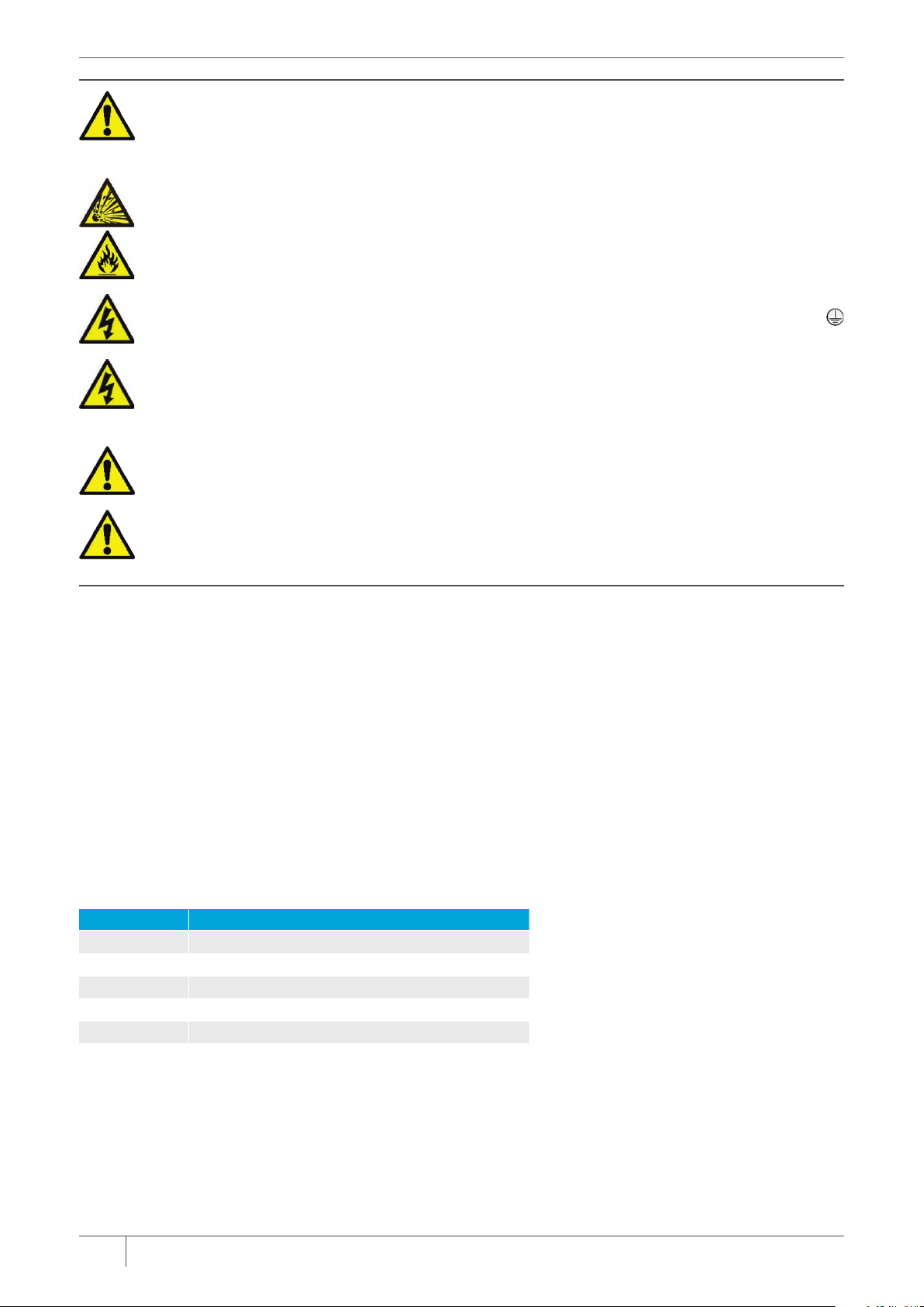
WARNING!
Risk of personal injury or injury to others. All personnel must be fully trained and adhere to local and, where
applicable, site-specific health and safety laws and guidelines.
It is the responsibility of the local organizations to enforce safe working practices at all times.
WARNING! – EXPLOSION OR COMBUSTION RISK
Observe the requirements in the certificates and the precautions and special conditions of use documented in this
manual (refer to the Equipment Marking Information, section 4.5 on page 7).
The equipment may be opened only when it is de-energized or the area has been designated as ‘safe’ at that time.
WARNING! – ELECTRIC SHOCK
Only connect to an earthed supply. This unit is a Class 1 construction and must be connected to a Protective Earth
connection (GND).
WARNING! – ELECTRIC SHOCK
This product must be connected to a power supply of the same voltage (V) and frequency (Hz) as indicated on the
product rating plate and provided in the Technical Data section on page 24 of this manual.
A supply cable with adequate rating must be used. Temperature de-rating must be considered.
CAUTION!
Position the equipment to avoid excessive heat, vibration, humidity, and dust.
CAUTION!
Failure to service or maintain the product, fitting non-approved parts, or carrying out non-approved alterations or
servicing can be dangerous and could affect the safety of the product. It may also invalidate the terms and conditions
of the product warranty.
LIMITS OF USE
To achieve optimum performance and safe operation the equipment must be operated within the limits detailed in the Technical
Data section on page 24 of this manual. Operation outside these limits can result in damage to the equipment or failure to
achieve the performance specified.
Pollution Degree 2
This equipment is designed for operation in Pollution Degree 2 environments (non-conductive, transient pollution where
occasionally a temporary conductivity caused by condensation must be expected).
Overvoltage Category II
Overvoltage protection for CATII equipment or instruments intended to be supplied for wiring (applicable to both plug-connected
and permanently connected equipment).
ADDITIONAL INFORMATION
List of Abbreviations
The following abbreviations and terms are used in this manual:
ACRONYM MEANING
BSPP
CCW
CW
ESP
SPCO
British standard pipe parallel (thread standard)
counter-clockwise (also anti-clockwise)
clockwise
Electrostatic precipitator
single pole, change-over (electrical switch)
Product Parts and Options
Please contact Goyen | Mecair or our local representative for more information on available spares kits, special tools, and
accessories for your instrument.
02 INSTALLATION AND OPERATION MANUAL – OWNER'S RECORD FFD MANUAL – FILTER FAILURE DETECTOR
Page 7

2 CERTIFICATION
CONFORMANCE AND RELATED STANDARDS
Goyen | Mecair hereby declares that this instrument—within the limits specified in this manual—complies with the essential
requirements and other provisions of the pursuant European Union Directives: Low Voltage Directive, EMC Directive, and ATEX
Directive.
For details refer to the Declaration of Conformance for this instrument or system (available on request from Goyen | Mecair or
our local representative).
ATEX Standards
In addition, the instrument has been designed to be compliant with the below standards.
EN 60079-0:2012 + A11:2013
Explosive atmospheres. Part 0: Equipment –
General requirements
EN 60079-15:2010
Explosive atmospheres.
Part 15: Equipment protection by type of
protection “n”
EN 60079-31:2009 AND EN 60079-31:2014
Explosive atmospheres –
Part 31. Equipment dust ignition protection
by enclosure “t”
Specifies the general requirements for the construction, testing and marking of electrical
equipment used in explosive atmospheres.
Specifies requirements for the construction, testing and marking for Group II electrical
equipment with type of protection, “n” intended for use in explosive gas atmospheres.
This standard should be read in conjunction with EN 60079-0.
Specifies requirements for design, construction and testing of electrical equipment and Ex
components.
03INSTALLATION AND OPERATION MANUAL – OWNER'S RECORD FFD MANUAL – FILTER FAILURE DETECTOR
Page 8

3 PRODUCT DESCRIPTION
3.1 COMPONENTS – SENSOR VARIANTS
Figure 1: FFD sensor
Standard Sensor
(up to 200°C)
3.2 OVERVIEW
The FFD is a Filter Failure Detector for the continuous monitoring of fabric-filter baghouses to identify bag-filter
degradation.
The instrument combines the benefits of Probe Electrification technology and dual local alarms with dual alarm
relays, and a scalable 4–20 mA output from a single, integrated unit to deliver pragmatic and dependable identification
of increases of dust emissions and for monitoring leaking or broken bags.
04 INSTALLATION AND OPERATION MANUAL – OWNER'S RECORD FFD MANUAL – FILTER FAILURE DETECTOR
Page 9

3.3 SENSOR
The sensor comprises a metal probe rod that protrudes into the stack and connects to the stack via the hexagonal
body connected to the sensor enclosure, which contains the advanced electronics module. The sensor is fitted to the
stack using a ½″
page 6 for details of ATEX-related conditions and requirements.
The FFD is suitable for use in applications of up to 200°C (390°F).
Adjustable Alarm Levels
Dual alarming enables operators to configure early warning and limit (high) alarm levels providing flexible sensitivity to suit
the process. Dust levels are averaged – or smoothed – using a ‘walking window’ filter to avoid triggering false alarms due
to temporary spikes in dust levels, e.g. during bag-filter cleaning cycles.
3.4 PRINCIPLE OF OPERATION
The FFD sensor utilizes Probe Electrification measurement technology. The sensor measures the interaction between
the particulate in the air stream and the sensing rod to induce a charge signature. The instrument extracts a specific
frequency band and filters out the DC current caused by direct particle collisions. The technology outperforms conventional
DC tribo-electric systems by extending the range over which the instrument has minimal cross-sensitivity to changing
velocity while remaining unaffected by the build-up of particulate on the sensing rod, thereby minimizing signal drift.
BSPP threaded socket and is secured with a lock nut. The instrument requires 24 V DC, nom. Refer to
05INSTALLATION AND OPERATION MANUAL – OWNER'S RECORD FFD MANUAL – FILTER FAILURE DETECTOR
Page 10

4 SENSOR SAFETY DESCRIPTION
4.1 HAZARDOUS AREAS
The sensor may be installed in a metal stack or duct containing hazardous dust, while any ancillary equipment must be
installed in the designated Safe Area. The sensor unit is mounted to the ductwork such that the metal probe rod protrudes
into the flow of the particulate to be monitored.
4.1.1 Hazardous Zone Classification
The instrument is suitable for use in the following Ex zones:
INSIDE STACK OUTSIDE STACK
Gas zone
Dust zone
4.2 CENELEC CODES
4.2.1 Gas Atmospheres
The marking for explosive gas atmospheres includes the following CENELEC codes (see also section 4.5 below):
• Ex nA IIB T6 Gc for the sensor enclosure.
• Ex nA IIB T3 Gc for the sensor body and probe when the maximum stack ambient is +200°C.
The nA applies to the non-sparking connections, and also signifies that the equipment is incapable in normal
operation of producing sparks or hot surfaces that may cause ignition.
4.2.2 Dust Atmospheres
The marking for explosive dust atmospheres includes the CENELEC codes (see also section 4.5 below):
• Ex tc IIIC T80°C Dc for the sensor enclosure.
• Ex tc IIIC T200°C Dc for the sensor body and probe when the maximum stack ambient is +200°C.
The tc applies to protection by enclosure, and also signifies that the equipment is incapable in normal operation
of producing sparks or hot surfaces that may cause ignition.
Zone 2 Zone 2
Zone 22 Zone 22
4.3 SPECIAL CONDITIONS OF SAFE USE FOR SENSOR ENCLOSURE
a) All connections to the equipment must not be inserted or removed unless the area in which the equipment is installed
is known to be non-hazardous, or the circuit to which it is connected has been de-energized. This includes the plugging/
unplugging of the screw terminals from the PCB-mounted headers.
b) Neither the enclosure nor any of the labels attached to it are to be rubbed with a dry cloth or anything else that might
cause a build-up of electrostatic charge.
c) A connection must be made between the earth stud on the outside of the enclosure and the duct wall. The connection
shall be made as follows
• The cable shall have a cross-sectional area of at least 4 mm².
• The cable shall be connected using an anti-vibration nut and washer or a similar arrangement of comparable integrity.
If the probe is removed while a potentially flammable dust or gas is present, this connection shall be maintained during the
withdrawal of the probe.
d) This equipment is suitable for an ambient temperature range of –20°C to +50°C and the standard range of atmospheric
pressure; the user/installer shall ensure that the process temperatures and pressures, including within the dust stack,
do not cause these parameters to be exceeded.
06 INSTALLATION AND OPERATION MANUAL – OWNER'S RECORD FFD MANUAL – FILTER FAILURE DETECTOR
:
Page 11

e) Cable Glands and Stopping Plugs certified to EN 60079-0 (e.g. Dust-protected ta/tb/tc; Increased safety Ex e;
Flameproof Ex d; Type of protection “n” Ex n) are acceptable provided they are fitted with the appropriate seal to the
enclosure and maintain a minimum ingress protection of IP64. (This seal may be incorporated within the gland or plug.)
f) The equipment must be powered from a nominal 24 V DC power supply that includes transient protection at no more
than 119 V DC. This requirement will be met if the power supply meets the requirements of the Low Voltage Directive.
g) If the equipment is likely to come into contact with aggressive substances (e.g. Acidic liquids or gases that may attach
metals or solvents that may attack polymeric materials relied upon for sealing), then it is the responsibility of the user
to take suitable precautions that prevent it from being adversely affected thus ensuring that the type of protection
(Dust exclusion Ex tc and Non-sparking device Ex nA) is not compromised.
4.4 SPECIAL CONDITIONS OF SAFE USE FOR SENSOR BODY AND PROBE
a) The ½″ sensor body must be mounted in the dust stack so that the PTFE insulator is positioned within the wall of the
dust stack, to protect the insulator from a build-up of electrostatic charge and to protect it from any possible impact.
b) Neither the PTFE insulator of the ½″ sensor body nor any of the labels attached to it are to be rubbed with a dry cloth
or anything else that might cause a build-up of electronic charge.
c) If the ½″ Sensor Body and Sensor Probe are used with a Sensor Enclosure, then a connection shall be made between
the stud on the Sensor Enclosure and the dust stack wall. The connection shall be made as follows:
• Thecableshallhaveacross-sectionalareaofatleast4mm².
• Thecableshallbeconnectedusingananti-vibrationnutandwasherorasimilararrangementofcomparableintegrity.
If the Probe is removed while a potentially flammable dust/air mixture is present, this connection shall be maintained during
the withdrawal of the Sensor Body and Probe.
d) If the equipment is likely to come into contact with aggressive substances (e.g. Acidic liquids or gases that may attack
metals or solvents that may affect polymeric materials relied upon for sealing), then it is the responsibility of the user
to take suitable precautions that prevent it from being adversely affected thus ensuring that the type of protection
(dust exclusion) is not compromised.
e) The ambient temperature range within the dust stack in which the ½″ Sensor Body and Probe are mounted must
be no more than –20°C to +200°C.
4.5 EQUIPMENT MARKING INFORMATION
WARNING! – ELECTRIC SHOCK
Potential Electrostatic Charging Hazard (see instructions).
WARNING!
Do not open when energized!
The FFD sensor unit has two labels applied to its enclosure: a serial number label and a label showing the ATEX-related
Ex/CE marking obtained by the manufacturer for this instrument.
The equipment in normal operation is incapable of producing arcs, sparks, or hot surfaces, which may cause ignitions, and
is designed to be installed and used in accordance with EN 60079-14:2014.
For details refer to the Special Conditions of Safe Use above.
ATEX
DUST ZONE ZONE 2/22
Certificate number: PCME15ATEX0002X
Inside stack (sensor body, probe)
Ex nA IIB T3 Gc
Ex tc IIIC T200°C Dc
Ta = –20°C to +200°C
Certification code:
Manufacturer’s name:
Manufacturing address:
Model number:
Year of manufacture:
Outside stack (enclosure)
Ex nA IIB T6 Gc
Ex tc IIIC T80°C Dc
Ta = –20°C to +50°C
PCME Ltd.
St Ives, Cambs, PE27 3GH, UK
as applicable
as applicable
A
II 3G/D
A
The probe does not generate heat; therefore, the surface temperature is dependent upon the stack temperature, maximal +200°C (390°F).
07INSTALLATION AND OPERATION MANUAL – OWNER'S RECORD FFD MANUAL – FILTER FAILURE DETECTOR
Page 12

5 SENSOR INSTALLATION
5.1 SAFETY INFORMATION
WARNING! – DANGER FROM PROCESS
It is possible that the sensors are to be installed in ducting containing process particulate that is hazardous
to health.
Unless the process conditions are known to be entirely safe, suitable precautions such as the use of breathing
apparatus or duct purging/ detoxifying must be employed before any entry is made into the duct for installation
or maintenance purposes. If in doubt, consult your local Safety Officer and/or local safety procedures.
WARNING! – ELECTRIC SHOCK
Ensure that only the cables types specified are used for powering and interconnection of equipment.
5.2 PREREQUISITES AND GUIDELINES
5.2.1 Choosing the Best Position for the Sensor
When selecting a mounting location for the sensor, the following guidelines are based on the related standardsB and
should be taken into consideration to ensure optimum performance of the instrument, safety, and for compliance
purposes.
The best position for the sensor unit is in a section of ductwork where the particulate has an even distribution and
the flow is linear. This would ideally be in a vertical or horizontal section of duct that has no bends or obstructions
for at least three duct diameters downstream or upstream. In many applications, a compromise must be made,
but the sensor should be fitted in a position that satisfies the majority of the below requirements.
NOTE:
The sensor must be fitted to metal ductwork in order to be electrically screened from interference signals
(see Grounding the Sensor below)
5.2.2 Location Requirements
When selecting a mounting location for the sensor the following should be taken into consideration for optimum
performance:
• In the longest, straightest, unrestricted section of ductwork available.
• In metallic ductwork (for non-metallic ducts contact Goyen | Mecair).
• Away from ambient or radiated temperatures greater than +50°C (120°F).
• Where possible, the equipment should be mounted out of direct sunlight, precipitation, and away from
running water.
• Hazardous Zones: refer to the Sensor Safety Description on page 6 for details of ATEX-related special conditions
and requirements.
5.2.3 Cabling Guidelines
Cables should be fixed such that they are free from excessive vibration and not under strain. Cables should
be secured in accordance with good engineering practice (e.g. using cable trays where possible) and careful
consideration should be given to the positioning of cables so that they are not damaged easily.
Cables should be routed to avoid sources of large electromagnetic fields, such as heavy switching gear. Care taken
during the installation of the cables ensures a long, maintenance-free life and avoids possible damage to the sensor.
B
The definitive guide for isokinetic sampling port location is given in standards ISO 9096 and EN 13284-1.
08 INSTALLATION AND OPERATION MANUAL – OWNER'S RECORD FFD MANUAL – FILTER FAILURE DETECTOR
Page 13

In summary, the cabling should be installed such that:
• Heavy vibration is minimized to prevent fatigue and failure.
• It is not vulnerable to accidental damage.
• It is away from sources of large electromagnetic fields (if possible).
5.2.4 Grounding the Sensor
For FDD sensors it is essential that the sensor body is grounded to the stack wall. This is necessary for Ex safety.
In addition, poorly grounded sensors may pick up external noise producing false high readings.
Ensure the installation complies with the following requirements:
• The sensor may only be fitted to a metal duct or stack. (If the stack is not metallic or you are concerned that the
stack may not provide a suitably earthed shield for the sensor, please contact Goyen | Mecair.)
• The grounding strap (or earth wire) provided must be connected to ensure the sensor body is securely grounded
to the metallic stack wall. The sensor is electrically grounded to the ductwork by the mechanical connection made
between the sensor and the socket, and also by the external grounding strap.
NOTE: The grounding strap must be connected between sensor enclosure and stack wall. Relying on the stack
connection only is not acceptable in hazardous areas!
• When connecting the grounding strap between sensor enclosure and stack wall leave sufficient length so that the
sensor can be removed and placed on the ground or platform for maintenance without disconnecting.
• For threaded connections: Do NOT put PTFE tape around the thread (as this can compromise the sensor
grounding connection)!
• If necessary, remove excessive rust from the thread and socket and apply a copper-loaded grease.
Surge Protection (Safety Grounding Cable)
To reduce the likelihood of damage from nearby lightning strikes, or from electrical surges due to high-power
equipment, run an additional earth cable (or grounding cable) between the sensor and the power supply.
The additional earth cable should follow exactly the same path as the sensor cable so as to ensure the closest
possible electrical coupling between them. Preferably, and if feasible, the two cables should be twisted together
loosely as they are laid. Alternatively, they may be clipped together at regular intervals along their length.
At the sensor end, the earth cable should be bonded to the sensor enclosure body, or to a point on the stack
immediately adjacent to the sensor head, using a low-resistance screw termination. At the power supply, the
earth cable should be bonded to the same mains earth point as is used to connect the power supply safety
grounding strap.
See below for information on cable lengths.
CABLE LENGTH GROUNDING WIRE CONDUCTOR AREA (mm²)
0–3 m (0–10 ft)
3–10 m (10–33 ft)
10–30 m (33–100 ft)
30–100 m (100–330 ft)
Above 100 m (330 ft)
not required
4
6
10
16
5.2.5 Running Cables between Sensor and Power Supply
CAUTION!
Do NOT route cables where they may be at risk from lightning damage (e.g. over exposed roofs).
• To prevent water from entering the instrument, mount all instruments and accessories with the cable entry
glands facing downward.
• After inserting and connecting a cable, fasten the cable glands tightly onto the cable to form a seal. Leave a little
slack in the cores.
• Cable sheathing must always penetrate the cable entry gland fully, and the gland must be fastened tightly to it.
• Where a cable run approaches the instrument from above, it must be run underneath the instrument and then
curved up to the cable gland.
• Leave sufficient slack in the cable to allow the sensor unit to be removed and placed on the ground/platform
for servicing.
09INSTALLATION AND OPERATION MANUAL – OWNER'S RECORD FFD MANUAL – FILTER FAILURE DETECTOR
Page 14

• Support cables at appropriate intervals. Where possible, use cable trays.
NOTE:
For EMC reasons (interference rejection and surge handling), all of the cable trays carrying signal cables
should be electrically continuous (i.e. the sections should be interconnected by heavy-gauge electrical
wiring) and they should be connected to Earth at multiple points along their length. Cable trays are
typically secured to grounded metal structures, which satisfies this requirement.
• The cable screen must be terminated correctly.
• Any unused cable glands must be blanked using an appropriate device.
• When connecting the sensor, the 4 off screws securing the enclosure cover lid should be coated with a small
amount of copper grease before refitting and securing the lid. Do not over-tighten the screws.
5.3 MOUNTING THE SENSOR
5.3.1 Safety Information
CAUTION! – PROBE DAMAGE
Take care when handling the sensor to avoid bending or damaging the probe. Probe damage may result
in inaccurate measurements.
CAUTION!
Do NOT try to rotate the sensor by twisting its enclosure as this can seriously damage the sensor.
5.3.2 Fitting the Sensor to the Stack
Figure 2: Fitting the sensor to the stack
1 Sensor enclosure
2 Heat shield
3 Lock nut (30 mm A/F)
4 Insulator
5 Probe rod
6 Stack connection socket (threaded)
7 ½″ BSPP thread
8 Hexagonal sensor body (22 mm A/F)
9 Earth stud assembly
10 Breather
11 M16 cable glands (2 off)
10 INSTALLATION AND OPERATION MANUAL – OWNER'S RECORD FFD MANUAL – FILTER FAILURE DETECTOR
Page 15

REQUIRED TOOLS
AND EQUIPMENT
Prepare the stack or duct to fit the sensor to as follows:
1. Drill a hole with an ID of at least ∅19 mm (¾″) suitable for a ½″ threaded sensor in the stack wall where the
sensor unit is to be located.
2. Fit a suitable socket [6] (based on the sensor-to-stack connection [7]). This must be securely welded to the stack.
The socket [6] should be installed at a slight upward angle, so that the probe rod points downward allowing any
condensate to drain off into the stack.
NOTE:
If the duct is not vertical, take care to ensure that the socket is slightly angled and does not point upward
to prevent water ingress. For more information on sensor location and pre-installation preparations
please contact Goyen | Mecair.
Alternatively, sockets can also be mounted on preformed backing plates, which are then mounted to the stack wall.
Next fit the sensor to the stack/duct as follows:
3. Referring to Figure 2 above, insert the sensor into the socket [6] and secure it by turning the hexagonal sensor
body [8] using a suitable spanner.
NOTE:
Ensure the cable glands [11] are facing downward and that the grounding strap (earth wire) securely
connects the sensor to the stack/duct via the earth stud assembly at the rear of its enclosure [9].
4. Tighten the lock nut [3] against the socket [6] to secure the sensor in position.
5.4 CONNECTING THE SENSOR
5.4.1 Safety Information
Standard toolkit
Spanner set (22/30 mm A/F) or adjustable spanner
Drilling, welding tools and consumables
WARNING!
Ensure the cabling is not connected to the control unit power during wiring.
CAUTION!
Do NOT try to rotate the sensor by its enclosure as this can seriously damage the sensor.
5.4.2 Sensor Connections
The sensor connections can be found below the raised control panel which carries the sensor controls and status
indicator. Refer to Figure 3 below for their location and the type of connectors.
Connect the power supply last, leave the cable gland (on the right) closest to the power connector free for this
purpose (see also Figure 6 on page 13).
Figure 3: Sensor PCB connections
11INSTALLATION AND OPERATION MANUAL – OWNER'S RECORD FFD MANUAL – FILTER FAILURE DETECTOR
Page 16

5.4.3 Relay Outputs
WARNING!
The relays and PCB tracks are not mains rated!
Any attempt to use the relays to switch mains could result in damage to the equipment and pose a threat
to the operator!
Referring to Figure 4 below, the contacts are shown in their normal (non-energized) state. Prepare a suitable cable
as described above and connect to the terminals using the second, free cable entry gland. Both relays are of type
SPCO, are volt free, and are not fail-safe in operation (i.e. they are not normally energized).
Figure 4: Connecting the sensor relays
5.4.4 4–20 mA Output
Figure 5: Connecting the 4–20 mA output
The FFD is fitted with a non-isolated 4–20 mA output capable of driving a 250Ω load. Referring to Figure 5, connect
to the 4–20 mA terminals as shown.
The 4–20 mA output is scaled from 0–200% of the high (limit) alarm setting. If, for example, the alarm is set
to 400 units, an emission level of 800 units will give an output current of 20 mA.
12 INSTALLATION AND OPERATION MANUAL – OWNER'S RECORD FFD MANUAL – FILTER FAILURE DETECTOR
Page 17

5.4.5 Connecting the Power Supply
Figure 6: Connecting the sensor power supply
The FFD sensor requires a power supply of between 16 V and 24 V DC @ 80 mA.
NOTE: Keep the length of exposed screen (known as a ‘pigtail’) to an absolute minimum (long pigtails degrade EMC
performance); however, the signal wires may be longer.
13INSTALLATION AND OPERATION MANUAL – OWNER'S RECORD FFD MANUAL – FILTER FAILURE DETECTOR
Page 18

6 SETTING UP THE FFD
6.1 SAFETY INFORMATION
WARNING! – HAZARDOUS VOLTAGES
Be aware that during the setup procedure, the FFD may be connected to the mains supply!
6.2 CONTROL PANEL OVERVIEW
Figure 7: FFD control panel overview
The FFD can be set up and operated using the controls located on the raised sensor control panel (see Figure 7 above):
• two rotary controls (upper/lower) for calibration,
• a MODE slide switch (bottom left) for calibrating the instrument and for setting the alarm delay period,
• a tricolour STATUS LED (at the top of the control panel) to indicate the current system status/alarms.
When the setup of the FFD is complete, replace and secure the enclosure cover lid with the 4 off screws. This prevents
accidental adjustment and unauthorized tampering.
14 INSTALLATION AND OPERATION MANUAL – OWNER'S RECORD FFD MANUAL – FILTER FAILURE DETECTOR
'
Page 19

6.3 SETUP PROCEDURE
NOTE: To avoid triggering an external alarm unit whilst setting up the FFD disconnect all connections from RELAY 1 and
RELAY 2 (see section 5.4.3 on page 12) by unplugging the headers.
The steps involved in setting up the FFD sensor are described in the following sections:
• STEP 1 – Preparation
• STEP 2 – Capture Process Information
• STEP 3 – Determine the Dust Level
• STEP 4 – Set the Alarm Levels
• STEP 5 – Set the Alarm Delay
• STEP 6 – Complete the Setup.
STEP 1 – Preparation
On the sensor control panel, set the controls to the following positions before switching ON the system:
1. Referring to Figure 8 below, turn the LOWER rotary control fully CCW (setting 1x).
2. Turn the UPPER rotary control fully CW (set to 10).
3. Set the MODE slide switch to RUN 1.
4. Switch ON power to the FFD sensor.
After an initial delay of approx. one second, the STATUS LED illuminates (ignore the colour of the LED, it is not important
at this point).
Figure 8: Setup procedure – Step 1
15INSTALLATION AND OPERATION MANUAL – OWNER'S RECORD FFD MANUAL – FILTER FAILURE DETECTOR
Page 20

STEP 2 – Capture Process Information
Capture some representative information from the plant. It is essential that the plant is running normally during this time.
NOTE:
Do not carry out this step on start-up or during a bag-cleaning cycle.
Figure 9: Setup procedure – Step 2
1. To begin collecting information, set the MODE slide switch to SET. The STATUS LED starts flashing to indicate that data
is being collected.
2. Run the data collection process as long as required (up to two hours maximum).
In general, a longer collection period will provide a more accurate representation of plant activity. However, 15 minutes is
typically sufficient to provide a good, representative sample.
NOTE:
If the FFD sensor is to be referenced against an isokinetic sample, the collection period must be the same
length as the sample run.
STEP 3 – Determine the Dust Level
Using the rotary controls, determine the Dust level from the process data collected in STEP 2 above.
• If the STATUS LED is flashing GREEN, do not adjust the lower control at this stage.
• If the STATUS LED is flashing RED, proceed as follows:
1. Referring to Figure 10, turn the LOWER rotary control CW, step-by-step through each setting (×1, ×10, …), until the
STATUS LED changes from flashing RED to flashing GREEN.
Figure 10: Setup procedure – Step 3 Calibrate the unit
2. Then slowly turn the UPPER rotary control CCW, until the STATUS LED changes from flashing GREEN to flashing RED.
16 INSTALLATION AND OPERATION MANUAL – OWNER'S RECORD FFD MANUAL – FILTER FAILURE DETECTOR
Page 21

3. Referring to Figure 11, move the MODE slide switch back to RUN 1.
Figure 11: Setup procedure – Step 3 Reset MODE slide switch
4. It is now possible to calculate the dust level from the control settings. The dust level is found by reading the position
of the upper rotary control and multiplying it by the position of the lower rotary control.
Example: in the above diagram, the upper rotary control reads 3 (see Figure 10 above) and the lower control reads 100
(see Figure 11 above), so the dust level can be calculated as follows:
Dust level = 3 x 100 = 300 units
NOTE: If it is not possible to change the LED to flashing RED, then the Sensitivity will need to be increased in the sensor
(see section 6.3.1.on page 18 for details)
STEP 4 – Set the Alarm Levels
Set the alarm levels based upon the dust level calculated in STEP 3 above. The STATUS LED on the FFD control panel is
typically RED at this point.
1. Decide the level at which the HIGH or limit alarm (RELAY 1) should be triggered.
NOTE:
In general, this will depend upon the type of plant as well as your local and national guidelines and/or
regulations.
2. Program the FFD sensor with this value by adjusting the rotary controls as follows:
a) Divide the required alarm level value by 1, 10, 100, or 1000 to give a number between 1 and 10, then
b) set the UPPER rotary control to this new value and
c) set the LOWER rotary control to the divisor (i.e. 1, 10, 100 or 1000).
Example: The limit set will depend upon national or local guidelines; otherwise a multiple of the dust level established
in STEP 3 is used to set an upper limit:
300 x 5 = 1500 units
If the required high alarm level is 1500 units, then
1500/1000 = 1.5
The UPPER settings control would then be set to 1.5 and the LOWER settings control would be set to 1000 (as shown in
Figure 12 below).
Figure 12: Setup procedure – Step 4
17INSTALLATION AND OPERATION MANUAL – OWNER'S RECORD FFD MANUAL – FILTER FAILURE DETECTOR
Page 22

The Early Warning Alarm (RELAY 2) is triggered at HALF the value set for RELAY 1, which in this example this
equates to:
1500/2 = 750 units
IMPORTANT NOTE:
Take care to ensure that the alarm level is set to more than TWICE the calculated dust level, otherwise RELAY 2 will be
triggered continuously.
STEP 5 – Set the Alarm Delay
Set the alarm delay period to a suitable value. The delay period is the period of time the FFD waits before activating
an alarm when the average plant emission exceeds the alarm setting (e.g. to avoid the alarm being triggered by the
bag-cleaning sequence).
The delay period can be either one or two minutes, depending on the type of process. Referring to Figure 13 below, adjust
the MODE slide switch as follows:
• For stable, continuous processes: set the MODE slide switch to RUN 1 (for an alarm delay period of 1 minute).
• For dynamic, unstable processes: set the MODE slide switch to RUN 2 (for an alarm delay period of 2 minutes).
• If you are not sure of the dynamics of your process: set the alarm delay period to RUN 1, and if RELAY 2 is intermittently
triggered, increase the alarm delay to 2 minutes bysetting it to RUN 2.
Figure 13: Setup procedure – Step 5
STEP 6 – Complete the Setup
1. Refit any connections that were removed (i.e. relays; see the Note on page 15).
2. Refit the enclosure cover lid and secure using 4 off screws. Check that the cover lid is fitted securely and that all cable
glands are sufficiently tight.
6.3.1 Changing the Sensor Sensitivity
Figure 14: Changing sensor sensitivity
By default, the sensitivity on the FFD sensor is set to LOW, i.e. the jumper is fitted to the lower pair of pins
on the JP2 link. The HIGH sensitivity setting is approx. 10 times more sensitive than LOW sensitivity.
If during STEP 2 (see page 16) of the setup procedure it is not possible to make the STATUS LED change colour from
GREEN to RED, then it is recommended to increase the sensor sensitivity.
18 INSTALLATION AND OPERATION MANUAL – OWNER'S RECORD FFD MANUAL – FILTER FAILURE DETECTOR
Page 23

Referring to Figure 14 above, adjust the sensor sensitivity by moving the jumper on the JP2 link (marked
SENSITIVITY) to HIGH or LOW as follows:
• For dust concentrations above approx. 2mg/m³ set the sensor sensitivity to LOW.
• For dust concentrations below approx. 2mg/m³ set the sensor sensitivity to HIGH.
IMPORTANT NOTE:
If the sensitivity is changed at any point during the setup procedure, data collection must be restarted – repeat the
setup procedure beginning with STEP 2 (on page 16).
19INSTALLATION AND OPERATION MANUAL – OWNER'S RECORD FFD MANUAL – FILTER FAILURE DETECTOR
Page 24

7 OPERATION
7.1 GENERAL OPERATION
When the sensor setup is complete, the operation of the FFD may be monitored from the front panel by checking the
STATUS LED. During normal operation, the system settings are as follows:
• The STATUS LED is illuminated GREEN to show that power is present, and no alarms exist.
• The STATUS LED flashes at one-minute intervals to indicate the completion of the averaging period.
• Both alarm relays will be non-energized.
7.2 ALARM OPERATION
The FFD has two independent alarm relay outputs whose levels are set during STEP 4 of the setup procedure (see page 17).
• RELAY 1 – High-level or Limit alarm: this alarm level can be adjusted by the user to suit the application.
• RELAY 2 – Early Warning alarm: this alarm level is fixed at HALF the level of the high alarm setting.
The STATUS LED indicates the alarm status (see table below for details).
STATUS LED MEANING EFFECT
GREEN Emissions are below HALF of the ‘high level’ setting (i.e. below
the early warning alarm threshold)
ORANGE Emissions are above HALF the ‘high level’ setting (this triggers
the EARLY WARNING alarm).
RED Emissions are above the ‘high level’ setting (this triggers the
HIGH alarm).
Rapid Pulsing
GREEN <> RED
Internal error
.
RELAY 1 – OFF
RELAY 2 – OFF
RELAY 1 – ON
RELAY 2 – OFF
RELAY 1 – ON
RELAY 2 – ON
The relays and 4–20 mA output retain their
pre-fault state (refer to Troubleshooting
on page 23).
The alarms are non-latching, so that when the plant returns to normal operation, the alarms are automatically cleared
(after the alarm delay period of one or two minutes).
Typically, the alarm relay outputs are connected to an external latching alarm module.
20 INSTALLATION AND OPERATION MANUAL – OWNER'S RECORD FFD MANUAL – FILTER FAILURE DETECTOR
Page 25

8 MAINTENANCE
8.1 SAFETY INFORMATION
WARNING!
Refer all servicing and maintenance to qualified service personnel.
WARNING! – EXPLOSION OR COMBUSTION RISK
Observe the requirements in the certificates and the precautions and Special Conditions of Use documented in this
manual. (Refer to the Equipment Marking Information, section 4.5 on page 7.)
The equipment may be opened only when it is de-energized or the area has been designated as ‘safe’ at that
time.
Refer to the Sensor Safety Description on page 6 for information on safe handling of the sensor in hazardous
zones.
WARNING!
Do not open when energized!
WARNING! – CONTAMINANTS
Disconnecting the unit from a positive pressure stack may result in hot stack gas or dust escaping. Use
protective gloves and other PPE.
Check for any specific health implications of process gas and/or dust before commencing maintenance.
CAUTION!
Do not allow moisture to penetrate the unit.
CAUTION! – PROBE DAMAGE
Take care when handling the sensor to avoid bending or damaging the probe. Probe damage may result in
inaccurate measurements.
CAUTION!
Do NOT try to rotate the sensor by its enclosure as this can damage the sensor.
CAUTION!
If a cable gland needs to be replaced, the replacement gland must be Ex-rated and must include an elastomer
seal. When fitting ensure that the lock nut must fully engage with the thread of the gland inside the enclosure.
8.2 PREVENTATIVE MAINTENANCE PROGRAMME
The preventative maintenance programme ensures that the FFD sensor remains reliable throughout its life. The frequency
of the maintenance programme is dependent upon the type of environment in which the instrument is used.
It is recommended that the programme is followed from one month after installation, then after 3-, 6-, or 12-monthly
intervals as deemed necessary.
21INSTALLATION AND OPERATION MANUAL – OWNER'S RECORD FFD MANUAL – FILTER FAILURE DETECTOR
Page 26

8.3 SENSOR HANDLING IN HAZARDOUS AREAS
8.3.1 Removing the Sensor from the Stack
WARNING! – NON-ISOLATED EQUIPMENT
Do NOT electrically disconnect the enclosure from the stack (i.e. break the ground/earth connection)
in the presence of hazardous dusts. Circulating currents in the ground system could create an ignition
hazard.
To disconnect the probe safely, remove the sensor from the stack, then disconnect the sensor from the
power source or control unit by unplugging the connection wire at the power source (in the designated
Safe Area).
Only once the sensor has been isolated from the power source, is it safe to disconnect the earth
connection between sensor enclosure and stack wall.
1. Switch OFF power to the sensor.
2. Remove the sensor in the usual way, ensuring that the grounding strap (earth wire) remains connected.
3. With the power OFF and the grounding strap in position, disconnect the sensor from the cable as follows:
a) Open the enclosure (see below for instructions).
b) Disconnect the cable (secure the bare wires in a safe dust-free manner).
c) Disconnect the grounding strap.
8.3.2 Opening the Sensor Enclosure in a Hazardous Area
WARNING! – EXPLOSION OR COMBUSTION RISK
The equipment may be opened only when it is de-energized or the area has been designated as ‘safe’
at that time.
1. Switch OFF and isolate mains power.
2. Open the enclosure by removing the lid.
3. Ensure no dust has settled in enclosure before replacing and securing the lid.
8.4 CLEANING THE SENSOR
WARNING!
POTENTIAL ELECTROSTATIC CHARGING HAZARD
Refer to the Special Conditions of Safe Use on pages 6 and 7 for details.
CAUTION!
(1) Do not allow moisture to penetrate the unit.
(2) Do not use solvents or oil-based cleaners to remove contamination or accumulations of dirt as these can
damage the surfaces, and the seals and insulator on the sensor.
The FFD is designed to require minimal servicing; however, the nature of many processes is such that a large build-up
of particulate may develop on the sensor rod. This build-up will often have no effect on the performance of the instrument,
but it is recommended that the build-up is periodically removed. The grounding strap should be sufficiently long to remove
the sensor and place it on the ground or platform without disconnecting.
Should the probe rod require cleaning, this can be performed by removing the sensor from the duct and thoroughly
cleaning the entire rod. Pay particular attention to the cleanliness of the insulator.
Wire wool or brushes may be used for cleaning sensor metal parts only, and for sticky or stubborn deposits a fast-drying
cleaning agent – note that this must have been approved for use in the particular type of hazardous zone!
Always refer to the Safety Information at the start of this section before commencing cleaning procedures.
NOTES:
(i) If using wire wool, clean the sensor parts using a rotational cleaning action to prevent scratches, particularly along the
sensor probe.
(ii) Ensure that the probe rod is thoroughly dried before refitting the sensor to the ductwork.
1. Remove the sensor unit from the ductwork (see section 8.3 above for instructions relating to sensor removal in
hazardous zones).
2. Thoroughly clean the probe rod and insulator as described above.
22 INSTALLATION AND OPERATION MANUAL – OWNER'S RECORD FFD MANUAL – FILTER FAILURE DETECTOR
Page 27

3. Clean off any excessive build-up from the sensor enclosure using a stiff brush or a damp cloth (do not use a dry cloth!).
4. Check that the lock nut moves freely.
5. Apply a small amount of copper slip or grease to the threads to prevent binding.
6. Refit the sensor unit to the ductwork (see section 8.3 above and follow instructions in reverse).
7. Inspect the connecting cable to ensure that it is not damaged or stressed.
8. If necessary, follow the Setup Procedure (see page 15) to reset the dust level.
8.5 TROUBLESHOOTING
NOTE: Always refer to the Safety Information at the start of this chapter.
8.5.1 General
Internal error
The FFD sensor indicates if an internal error has occurred.
Symptom: If this occurs, the STATUS LED will pulse rapidly between GREEN and RED (see also the table on page 20).
The relays and 4–20 mA output will remain in the state present before communication was lost.
Solution: Switch OFF power to the FFD sensor, wait five seconds, then switch ON power to reset the sensor.
If this does not remedy the problem, check the sensor and connecting cables for damage or water ingress.
Sensor not working
On new installations, ensure that the sensor has been connected correctly, both at the FFD sensor and the power
supply.
Solution: On existing installations, carefully check along the full length of the sensor cable for any signs of damage.
On installations where more than one FFD sensor is present, try substituting a known working sensor for the ‘faulty’
channel. If the problem is cleared with the working sensor, it is possible that the sensor has a fault and should be
returned to Goyen | Mecair for evaluation and repair.
8.5.2 Alarms
For information on alarm states and on resetting the FFD sensor refer to Alarm Operation on page 20.
23INSTALLATION AND OPERATION MANUAL – OWNER'S RECORD FFD MANUAL – FILTER FAILURE DETECTOR
Page 28

9 TECHNICAL DATA
9.1 PROCESS AND APPLICATION CONDITIONS
Stack temperature range
Flue gas velocity
Dust level response
Application conditions
Location
Altitude category
9.1.1 User Controls and Functions
Reference period
Alarm levels
Alarm delay period
Data smoothing
9.2 SENSOR SPECIFICATION
Sensor variants
Weight
Probe rod material
Cable entries
Ambient temperature range
Dimensions
Protection rating
Material
Power supply voltage
Current consumption
Local outputs
C
C
–20 to 200°C (–4 to 390°F)
SENSOR – KEY DATA
>4 m/s
<1 to 500 mg/m³ (dependent upon application)
Suitable for measurement in non-condensing flue gases.
Note: not recommended for deployment downstream of ESPs or in applications with
water droplets or mist at monitoring point.
ENVIRONMENTAL INFORMATION
This equipment is for outdoor or sheltered use.
2,000 m (6,500 ft.), max.
1–120 minutes (user definable)
• AlarmLevel1:adjustablefrom2to10,000units
• AlarmLevel2:fixed(50%ofAlarmLevel1)
1 or 2 minutes
One-minute data averaging
FFD SENSOR
Standard sensor: 0–200°C (up to 390°F)
approx. 1930 g (4.3 lb)
316 Stainless Steel, PTFE (insulator)
2× M16 cable glands
ENCLOSURE
–20 to +50°C (–4 to 120°F)
W 111 ×
H 135 x D 74 mm (4.4 × 5.3 × 3 in.), excl. cable glands
IP65
Die-cast aluminium LM6M (epoxy coated)
POWER REQUIREMENTS
16–24 V DC
max. 100 mA
I/O
2× Alarm relays:
• volt-freeSPCO
• currentrating1ADC(@30V)percontact
• non-fail-safeoperationonly.
1× 4–20 mA output: 250Ω, non-isolated.
C
At monitoring point. Please note that imperial temperatures given are nominal values.
24 INSTALLATION AND OPERATION MANUAL – OWNER'S RECORD FFD MANUAL – FILTER FAILURE DETECTOR
Page 29

9.2.1 Dimensioned Drawing – Sensor
9.3 SENSOR OPTIONS
Rod lengths
Stack connection
Hazardous zone
classification
100 mm (4″), 200 mm (8″), 250 mm (10″), 300 mm (12″), 400 mm (16″), 500 mm (20″), 600 mm (24″), 800 mm (32″),
1000 mm (40″).
Note: Imperial measurements are nominal values.
½″ BSPP (female)
Note: The opening/port hole in the stack wall must have an ID of at least ∅19 mm (¾″).
See page 10 for details on mounting the sensor.
ATEX zone 2/22 (Cat. 3G/D)
Note:
NEMA equivalents: Class I, Division 2 and Class II, Division 2
9.4 CABLING
All cabling must be suitable for use in hazardous zones.
All cabling should be rated for use up to +65°C (150°F) at least to allow for an ambient temperature of up to +50°C (120°F).
Cables supplied by Goyen | Mecair meet these requirements.
For special instructions and requirements relating to the installation of sensors in hazardous zones refer to the Sensor
Safety Description on page 6 and to the Sensor Installation on page 8.
25INSTALLATION AND OPERATION MANUAL – OWNER'S RECORD FFD MANUAL – FILTER FAILURE DETECTOR
Page 30

GENERAL NOTICES
COMPLIANCE
Waste of Electrical and Electronic Equipment (WEEE) Directive (2012/19/EU)
This symbol, if marked on the product or its packaging, indicates that this product must not be disposed of with general
household waste. In the European Union and many countries, separate collection systems have been set up to handle the
recycling of electrical and electronic waste.
Disposing of this product correctly helps prevent potentially negative consequences for the environment and human health.
The recycling of materials helps conserve natural resources.
In countries outside the EU:
Dispose of this product at a collection point for the recycling of electrical and electronic equipment, according to local government
regulations.
RoHS Compliance Statement
Goyen | Mecair is compliant with EU Directive 2011/65/EU on the restriction of the use of certain hazardous substances in
electrical and electronic equipment (RoHS).
List of Materials (ISO 14001)
The information is being provided to comply with ISO 14001 Environmental Management, which is part of EMAS, the European
Eco-Management and Audit Scheme to reduce waste and energy use, helping organizations improve efficiency, and providing
assurance to internal and external stakeholders that environmental impact is being measured and improved.
The following table provide a list of materials used in the construction of this product.
SENSOR – MATERIAL WHERE USED
316 Stainless steel Sensor body and rod
Aluminium alloy Enclosure
Electronic components Sensor electronics
Fibreglass PCB
PTFE Insulator
26 INSTALLATION AND OPERATION MANUAL – OWNER'S RECORD FFD MANUAL – FILTER FAILURE DETECTOR
Page 31

NOTES
27INSTALLATION AND OPERATION MANUAL – OWNER'S RECORD FFD MANUAL – FILTER FAILURE DETECTOR
Page 32

CLEANAIRSYSTEMS.com
© 2019 Pentair Clean Air Systems reserves the right to change product designs and specifications without notice.
Goyen FFD FILTER FAILURE DETECTOR Installation and Operation Manual Issue01 05/19
 Loading...