

Pentair Pool Products GMSV4A, GMSV2A33T, GMSV6C, GMSV2A3T, GMSV4A5T Operating Instructions, Performance, Specifications And Parts Manual
...Page 1
SHURflo Operating Instructions, Performance,
Specifications and Parts Manual
Please read and save this Repair Parts Manual. Read this manual and the General Operating Instructions carefully before attempting to assemble, install,
operate or maintain the product described. Protect yourself and others by observing all safety information. The Safety Instructions are contained in the
General Operating Instructions. Failure to comply with the safety instructions accompanying this product could result in personal injury and/or property
damage! Retain instructions for future reference.
Viton Models GMSV2A, GMSV4A, GMSV6C, GMSV2A3T, GMSV2A33T,
GMSV4A5T, GMSV4A53T, GMSV6C7T and GMSV6C73T
Teflon® Models GMST2A, GMST4A, GMST6C, GMST2A3T, GMST2A33T,
GMST4A5T, GMST4A53T, GMST6C7T and GMST6C73T
SHURflo 316 Stainless Steel Rotary
Close-Coupled External Gear Pumps
Refer to form L-4082 for General Operating and Safety Instructions and Applicable Warranty.
Description
SHURflo self-priming, positive displacement, external rotary gear pumps operate bi-directionally (reversible) and provide a
nearly pulseless flow for a wide range of industrial, marine, agricultural, and commercial chemical-duty applications. Mounted
directly to NEMA frame AC Totally-Enclosed Fan-Cooled (TEFC) motors using an easy-installation package, or as pump heads
only for custom installations. Single-phase motors are thermally overload protected; 3-phase motors are not. Ryton PPS
(Polyphenylene Sulfide) spur gears provide quiet operation and chemical compatibility with no metal-to-metal contact.
Pumps can operate in a temperature range of 32° to 280° F.
Quality features include a keyed 316 stainless steel shaft supported by a ball bearing and carbon graphite bushings. Wet-end
parts are constructed of 316 stainless steel, Ryton PPS, graphite, graphoil, carbon, ceramic, and Viton or Teflon
Uses: For use with non-particulate and non-abrasive fluids compatible with pump wet-end construction component materials.
• Capacities up to 24.8 GPM.
• Maximum pressure to 125 PSI and working casing pressure to 200 PSI.
• Max. RPM: 1725.
• Suction lift to 19.5 ft.
• Temperature ranges from 32° to 280° F.
• Large female NPT ports allow use with viscous fluids.
• Pumps are close-coupled with electric motors to handle up to 500 SSU at 1725 RPM or run at reduced speeds to handle
a wide range of pump fluid viscosities and specific gravity up to 100,000 SSU. (Maximum torque loads are found in the
performance chart.)
®
• Viton or Teflon
external flush to handle viscosities beyond 2000 SSU.
• Pumps can operate bi-directionally (reversible).
REPAIR SEALS AND OPTIONS – Standard seals are Viton or Teflon
located in the repair parts list pages in the owner’s manual. When switching between standard and optional mechanical seals, be
sure to order the matching o-rings in the same material. These can be found in the repair parts list pages of this manual.
Optional Close-Coupled Gear Speed Reducers are available that mount directly between pump and motor to reduce pump speed
for high viscosity or high specific gravity applications (See Appendix 2).
NOTE: This series of gear pumps is also available as pedestal models for custom applications.
mechanical seals (standard) with carbon on ceramic faces with engineered flush chamber for internal or
®
(Buna-N is optional) with carbon on ceramic faces. Seals can be
®
.
WARNING: Do not use to pump flammable or explosive fluids such as gasoline, fuel oil, kerosene, etc. Do not use in flammable
and/or explosive atmospheres. When pumping hazardous or dangerous materials, use only in a room or area designated for that
purpose. For your protection, always wear proper clothing, eye protection, etc. in case of any malfunction. For proper handling techniques and cautions, contact your chemical supplier, insurance company and local agencies (fire dept., etc.). Failure to comply with this warning could result in personal injury and/or property damage.
Form L-4089 (2/17)
Page 2
SHURflo Operating Instructions, Performance,
Specifications and Parts Manual
Viton Models GMSV2A, GMSV4A, GMSV6C, GMSV2A3T, GMSV2A33T,
®
Teflon
GMSV4A5T, GMSV4A53T, GMSV6C7T and GMSV6C73T
Models GMST2A, GMST4A, GMST6C, GMST2A3T, GMST2A33T,
GMST4A5T, GMST4A53T, GMST6C7T and GMST6C73T
SHURflo 316 Stainless Steel Rotary
Close-Coupled External Gear Pumps
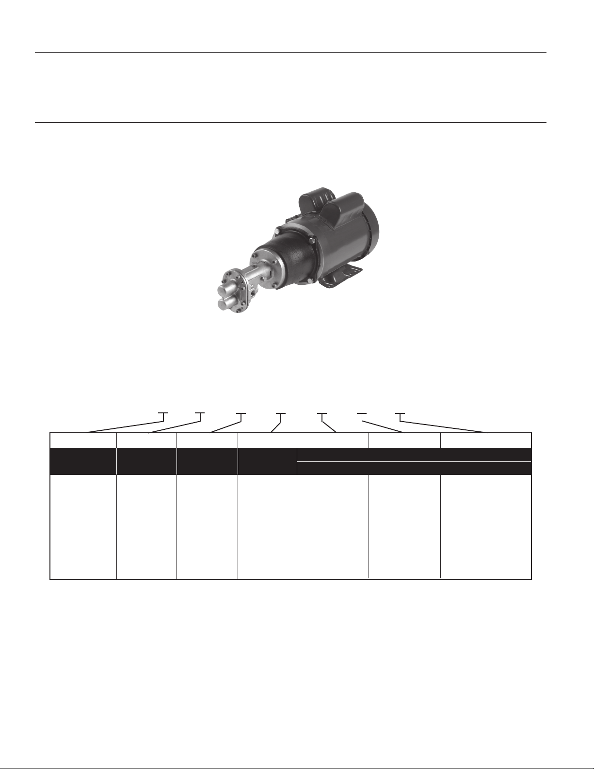
Model Ordering Codes and Options
Example Model: GMSV4A (will require 1
1
⁄2 HP ODP motor with >1.15 Service Factor*)
(Model pictured above is pump head without motor.)
(1) (2) (3) (4) (5) (6) (7)
GM S V 4 A
1st 2nd 3rd 4th 5th 6th 7th
Mounting Material Seal Gear** Motor-Mounted Only
(Mech) Size: Ports Brackets HP AC Type
GM: Gear
Motor
Mount
NOTE: Not all order code combinations (configurations) are standard models available from the manufacturer. Custom model configurations may require ordering
standard components and/or optional parts that will need to be assembled by the customer.
Manufacturer reserves the right to change model order codes, standard models, specifications, and performance without notification.
(*) ODP motors have > 1.15 service factors. Due to service factor, it is recommended TEFC motors are oversized by one HP increment.
(**) Gears are made of Ryton PPS (Polyphenylene Sulfide).
Maximum motor speed is 1725 RPM.
S: 316
Stainless
Steel
V: Viton
T: Teflon
2: 3/8”
4: 1/2”
6: 1”
A: 56C
B: 143/145TC
C: 182/184TC
1: 1/3
2: 1/2
3: 3/4
4: 1
5: 11⁄2
6: 2
7: 3
“Blank”: no code
single phase
ODP motor
3: 3 phase ODP
motor
T: 1 phase TEFC
3T: 3 phase TEFC
Form L-4089 (2/17)
2
Page 3
SHURflo Operating Instructions, Performance,
Specifications and Parts Manual
Viton Models GMSV2A, GMSV4A, GMSV6C, GMSV2A3T, GMSV2A33T,
GMSV4A5T, GMSV4A53T, GMSV6C7T and GMSV6C73T
Teflon® Models GMST2A, GMST4A, GMST6C, GMST2A3T, GMST2A33T,
GMST4A5T, GMST4A53T, GMST6C7T and GMST6C73T
Performance (with Oil)
Viton Teflon GPM Pumping 10 Wt. Oil at 70° F (500 SSU)
Pump Pump *Port Max. Input Pump Suction** Free Flow 25 PSI 50 PSI 75 PSI 100 PSI 125 PSI
Models Models Size Torque in.-lbs. RPM Lift (ft) GPM HP GPM HP GPM HP GPM HP GPM HP GPM HP
GMSV2A GMST2A 3/8” 45 900 1.5 2.5 1/4 2.5 1/4 2.4 1/4 2.3 1/4 2.1 1/4 1.8 1/3
GMSV2A GMST2A 3/8” 45 1200 2.2 3.3 1/4 3.3 1/4 3.2 1/4 3.1 1/3 2.9 1/3 2.6 1/2
GMSV2A GMST2A 3/8” 45 1725 3.5 4.8 1/4 4.8 1/3 4.7 1/2 4.6 1/2 4.4 3/4 4.1 3/4
GMSV2A3T GMST2A3T 3/8” 45 1725 3.5 4.8 1/4 4.8 1/3 4.7 1/2 4.6 1/2 4.4 3/4 4.1 3/4
GMSV2A33T GMST2A33T 3/8” 45 1725 3.5 4.8 1/4 4.8 1/3 4.7 1/2 4.6 1/2 4.4 3/4 4.1 3/4
GMSV4A GMST4A 1/2” 90 900 5.1 5.6 1/3 5.5 1/3 5.4 1/2 5.3 3/4 5.0 1 4.5 1
GMSV4A GMST4A 1/2” 90 1200 6.7 7.5 1/3 7.4 1/2 7.3 3/4 7.2 1 6.9 1 6.4 1
GMSV4A GMST4A 1/2” 90 1725 12.3 10.8 1/2 10.7 3/4 10.6 3/4 10.5 1 10.2 11⁄2 9.7 11⁄2
GMSV4A5T GMST4A5T 1/2” 90 1725 12.3 10.8 1/2 10.7 3/4 10.6 3/4 10.5 1 10.2 1
1
⁄2 9.7 11⁄2
GMSV4A53T GMST4A53T 1/2” 90 1725 12.3 10.8 1/2 10.7 3/4 10.6 3/4 10.5 1 10.2 11⁄2 9.7 11⁄2
GMSV6C GMST6C 1” 160 900 8.1 12.6 1/2 12.5 3/4 12.3 1 12.1 1 11.7 11⁄2 11.1 11⁄2
GMSV6C GMST6C 1” 160 1200 11.7 16.7 3/4 16.6 1 16.4 11⁄2 16.2 11⁄2 15.8 2 15.2 2
GMSV6C GMST6C 1” 160 1725 19.5 24.8 3/4 24.7 1 24.5 1
1
⁄2 24.3 2 23.9 3 23.3 3
GMSV6C7T GMST6C7T 1” 160 1725 19.5 24.8 3/4 24.7 1 24.5 11⁄2 24.3 2 23.9 3 23.3 3
GMSV6C73T GMST6C73T 1” 160 1725 19.5 24.8 3/4 24.7 1 24.5 11⁄2 24.3 2 23.9 3 23.3 3
Test data taken on SAE 10 wt. oil at 70° F. (500 SSU).
Performance in water will decrease by about 10%, and HP required will also be reduced by 10% (see the chart below).
Pump performance when pump is new. As pump wears, the performance will decrease.
(*) Female NPT inlet and outlet (in inches).
(**) Suction lift requires wetted gears and primed seal chamber.
NOTES: Max. PSI = 125, Max. Viscosity = 500 SSU at 1725 RPM with standard spur gears, Max. RPM = 1725
Max. Specific Gravity = 1.1 at 125 PSI, up to 1.6 at lower PSI & viscosity. Max. Input Torque = See chart above.
Reverse Rotation = Pumps can be run in reverse rotation.
The pump relationship between volume (GPM), pressure (PSI), speed (RPM) and horsepower is shown on performance chart in Shurflo Motor Manual
form L-4082. When pumping a more viscous liquid, a slower speed, a larger pipe size pump, and possibly a larger motor should be selected.
Manufacturer reserves the right to change performance without notification.
Performance (with Water)
Viton Teflon GPM Pumping Water at 90° F (31 SSU)
Pump Pump *Port Max. Input Pump Suction** Free Flow 25 PSI 50 PSI 75 PSI 100 PSI 125 PSI
Models Models Size Torque in.-lbs. RPM Lift (ft) GPM HP GPM HP GPM HP GPM HP GPM HP GPM HP
GMSV2A GMST2A 3/8” 45 900 1.2 2.4 1/4 2.3 1/4 2.1 1/4 1.8 1/4 1.5 1/3 1.1 1/3
GMSV2A GMST2A 3/8” 45 1200 1.8 3.2 1/4 3.1 1/4 2.9 1/3 2.6 1/3 2.3 1/2 1.9 1/2
GMSV2A GMST2A 3/8” 45 1725 3.0 4.6 1/3 4.5 1/2 4.2 1/2 4.0 1/2 3.7 3/4 3.3 3/4
GMSV2A3T GMST2A3T 3/8” 45 1725 3.0 4.6 1/3 4.5 1/2 4.2 1/2 4.0 1/2 3.7 3/4 3.3 3/4
GMSV2A33T GMST2A33T 3/8” 45 1725 3.0 4.6 1/3 4.5 1/2 4.2 1/2 4.0 1/2 3.7 3/4 3.3 3/4
GMSV4A GMST4A 1/2” 90 900 4.5 5.5 1/4 5.1 1/4 4.5 1/3 4.1 1/3 3.7 1/2 3.1 1/2
GMSV4A GMST4A 1/2” 90 1200 6.0 7.3 1/3 7.0 1/3 6.3 1/2 5.9 1/2 5.5 3/4 4.9 3/4
GMSV4A GMST4A 1/2” 90 1725 11.0 10.5 1/2 10.2 1/2 9.5 3/4 9.1 3/4 8.7 1 8.1 1
1
⁄2
GMSV4A5T GMST4A5T 1/2” 90 1725 11.0 10.5 1/2 10.2 1/2 9.5 3/4 9.1 3/4 8.7 1 8.1 1
GMSV4A53T GMST4A53T 1/2” 90 1725 11.0 10.5 1/2 10.2 1/2 9.5 3/4 9.1 3/4 8.7 1 8.1 1
GMSV6C GMST6C 1” 160 900 7.0 12.6 1/2 12.0 3/4 10.9 3/4 10.1 1 9.1 1
GMSV6C GMST6C 1” 160 1200 10.0 16.7 3/4 16.1 3/4 15.0 1 14.2 1
GMSV6C GMST6C 1” 160 1725 17.0 24.0 1 23.4 1 22.3 1
1
⁄2 21.5 2 20.5 3 19.5 3
1
⁄2 13.2 2 12.2 2
1
⁄2 8.1 2
GMSV6C7T GMST6C7T 1” 160 1725 17.0 24.0 1 23.4 1 22.3 11⁄2 21.5 2 20.5 3 19.5 3
GMSV6C73T GMST6C73T 1” 160 1725 17.0 24.0 1 23.4 1 22.3 11⁄2 21.5 2 20.5 3 19.5 3
Test data taken with water at 90° F. (31 SSU).
Pump performance when pump is new. As pump wears, the performance will decrease.
(*) Female NPT inlet and outlet (in inches). (**) Suction lift requires wetted gears and primed seal chamber.
NOTES: Max. PSI = 125 , Max. Viscosity = 500 SSU at 1725 RPM with standard spur gears, Max. RPM = 1725
Max. Specific Gravity = 1.1 at 125 PSI, up to 1.6 at lower PSI & viscosity. Max. Input Torque = See chart above.
Reverse Rotation = Pumps can be run in reverse rotation.
The pump relationship between volume (GPM), pressure (PSI), speed (RPM) and horsepower is shown on performance chart in Shurflo Motor Manual
form L-4082. When pumping a more viscous liquid, a slower speed, a larger pipe size pump, and possibly a larger motor should be selected.
Manufacturer reserves the right to change performance without notification.
Form L-4089 (2/17)
3
Page 4
SHURflo Operating Instructions, Performance,
Specifications and Parts Manual
Viton Models GMSV2A, GMSV4A, GMSV6C, GMSV2A3T, GMSV2A33T,
®
Teflon
GMSV4A5T, GMSV4A53T, GMSV6C7T and GMSV6C73T
Models GMST2A, GMST4A, GMST6C, GMST2A3T, GMST2A33T,
GMST4A5T, GMST4A53T, GMST6C7T and GMST6C73T
SHURflo 316 Stainless Steel Rotary
Close-Coupled External Gear Pumps
Specifications for Pump Heads Only (Motors not included)
PUMP CONSTRUCTION (Wet End)
NEMA Shaft,
Motor Pump Required Body & Keys Shipping
Frame Max. Shaft Motor Motor Cover Gear & Gasket O-Rings & Weight
Model Required RPM Size Shaft Adapter Port* Castings Material Clip Material Seals** (lbs.)
Viton Models
GMSV2A 56C 1725 1/2 Keyed 5/8 Keyed CI 3/8 316 SS Ryton PPS 316 SS Graphoil Viton 8.9
GMSV4A 56C 1725 5/8 Keyed 5/8 Keyed CI 1/2 316 SS Ryton PPS 316 SS Graphoil Viton 17.5
GMSV6C 182/184TC 1725 20mm Keyed 1
Teflon Models
GMST2A 56C 1725 1/2 Keyed 5/8 Keyed CI 3/8 316 SS Ryton PPS 316 SS Graphoil Teflon
GMST4A 56C 1725 5/8 Keyed 5/8 Keyed CI 1/2 316 SS Ryton PPS 316 SS Graphoil Teflon
GMST6C 182/184TC 1725 20mm Keyed 1
SS = Stainless Steel CI = Cast Iron CG = Carbon Graphite Ryton = PPS (Polyphenylene Sulfide)
(*) Female NPT inlet and outlet (in inches).
(**) Standard Shaft Seals have carbon on ceramic faces and 316 SS components.
NOTE: Driver data is subject to change without notice; see label on driver for specifications and wiring information.
Manufacturer reserves the right to change specifications without notification.
1
⁄8 Keyed CI 1 316 SS Ryton PPS 316 SS Graphoil Viton 23.1
®
8.9
®
1
⁄8 Keyed CI 1 316 SS Ryton PPS 316 SS Graphoil Teflon® 23.1
17.5
Form L-4089 (2/17)
4
Page 5
SHURflo Operating Instructions, Performance,
Specifications and Parts Manual
Viton Models GMSV2A, GMSV4A, GMSV6C, GMSV2A3T, GMSV2A33T,
GMSV4A5T, GMSV4A53T, GMSV6C7T and GMSV6C73T
Teflon® Models GMST2A, GMST4A, GMST6C, GMST2A3T, GMST2A33T,
GMST4A5T, GMST4A53T, GMST6C7T and GMST6C73T
Specifications for Standard Motor-Mounted Models
PUMP CONSTRUCTION (Wet End)
Shaft, O-Rings
AC Pump Body & Keys & Ship
Motor Motor NEMA Motor Motor Shaft Motor Motor Cover Gear & Gasket Seals Wt.
Model HP Type Frame Voltage* Amps PH** RPM Size Shaft Adapter Port*** Casting Material Clips Material **** (lbs.)
Viton Models
GMSV2A3T 3/4 TEFC 56C 115/230 11.2/5.6 1 1725 1/2 Keyed 5/8 Keyed CI 3/8 316 SS Ryton 316 SS Graphoil Viton 36.9
GMSV2A33T 3/4 TEFC 56C 230/460 2.6/1.3 3 1725 1/2 Keyed 5/8 Keyed CI 3/8 316 SS Ryton 316 SS Graphoil Viton 35.9
GMSV4A5T 1
GMSV4A53T 1
GMSV6C7T 3 TEFC 182/184TC 230 14.7 1 1725 20mm Keyed 1
GMSV6C73T 3 TEFC 182/184TC 230/460 8.2/4.1 3 1725 20mm Keyed 1
Teflon Models
GMST2A3T 3/4 TEFC 56C 115/230 11.2/5.6 1 1725 1/2 Keyed 5/8 Keyed CI 3/8 316 SS Ryton 316 SS Graphoil Teflon 36.9
GMST2A33T 3/4 TEFC 56C 230/460 2.6/1.3 3 1725 1/2 Keyed 5/8 Keyed CI 3/8 316 SS Ryton 316 SS Graphoil Teflon 35.9
GMST4A5T 1
GMST4A53T 1
GMST6C7T 3 TEFC 182/184TC 230 14.7 1 1725 20mm Keyed 1
GMST6C73T 3 TEFC 182/184TC 230/460 8.2/4.1 3 1725 20mm Keyed 1
SS = Stainless Steel CI = Cast Iron CG = Carbon Graphite Ryton = PPS (Polyphenylene Sulfide) TEFC = Totally-Enclosed Fan-Cooled Motor
(*) Motors are rated at 60 hertz only.
(**) Single-phase motors are thermally overload protected (reset may be automatic or manual); 3-phase motors are not thermally protected.
(***) Female NPT inlet and outlet (in inches).
(****) Standard Shaft Seals have carbon on ceramic faces and 316 SS components.
NOTE: Driver data is subject to change without notice; see label on driver for specifications and wiring information.
Manufacturer reserves the right to change specifications without notification.
1
⁄2 TEFC 56C 115/230 18.4/9.2 1 1725 5/8 Keyed 5/8 Keyed CI 1/2 316 SS Ryton 316 SS Graphoil Viton 60.5
1
⁄2 TEFC 56C 3 5/8 Keyed 5/8 Keyed CI 1/2 316 SS Ryton 1144 Steel Graphoil Viton 53.5
1
⁄2 TEFC 56C 115/230 18.4/9.2 1 1725 5/8 Keyed 5/8 Keyed CI 1/2 316 SS Ryton 316 SS Graphoil Teflon 60.5
1
⁄2 TEFC 56C 3 5/8 Keyed 5/8 Keyed CI 1/2 316 SS Ryton 1144 Steel Graphoil Teflon 53.5
230/460
190/380
230/460
190/380
4.8/2.4
5/2.5
4.8/2.4
5/2.5
1750
1450
1750
1450
1
⁄8 Keyed CI 1 316 SS Ryton 316 SS Graphoil Viton 120.1
1
⁄8 Keyed CI 1 316 SS Ryton 316 SS Graphoil Viton 88.1
1
⁄8 Keyed CI 1 316 SS Ryton 316 SS Graphoil Teflon 120.1
1
⁄8 Keyed CI 1 316 SS Ryton 316 SS Graphoil Teflon 88.1
Form L-4089 (2/17)
5
Page 6
SHURflo Operating Instructions, Performance,
Specifications and Parts Manual
Viton Models GMSV2A, GMSV4A, GMSV6C, GMSV2A3T, GMSV2A33T,
®
Teflon
GMSV4A5T, GMSV4A53T, GMSV6C7T and GMSV6C73T
Models GMST2A, GMST4A, GMST6C, GMST2A3T, GMST2A33T,
GMST4A5T, GMST4A53T, GMST6C7T and GMST6C73T
SHURflo 316 Stainless Steel Rotary
Close-Coupled External Gear Pumps
Dimensions
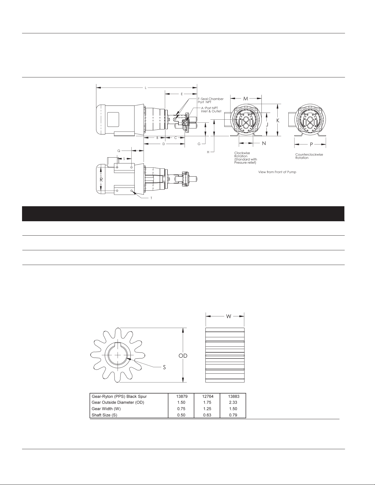
Figure 1
Port Dimensions (in inches)
Model No. A* B C D E F* G** H** J** K** L** M** N P** Q** R** S** T**
GMSV2A†, GMSV2A3T, GMSV2A33T 3/8 4.50 4.12 8.58 6.67 1/8 2.85 3.50 4.91 6.32 21.73 6.59 3.00 6.50 2.63 4.88 3.00 0.34
GMST2A†, GMST2A3T, GMST2A33T
GMSV4A†, GMSV4A5T, GMSV4A53T 1/2 4.50 4.90 9.35 7.46 1/8 2.75 3.50 5.00 6.32 25.12 6.59 3.50 6.50 2.63 4.88 3.00 0.34
GMST4A†, GMST4A5T, GMST4A53T
GMSV6C†, GMSV6C7T, GMSV6C73T 1 4.50 5.88 10.10 9.08 1/8 2.50 3.50 5.39 8.75 28.46 8.47 4.40 9.00 2.75 7.50 4.50 0.41
GMST6C†, GMST6C7T, GMST6C73T
(†) Pump head only (motor not included).
(*) Standard NPT (female) pipe thread inlet and outlet (in inches).
(**) This dimension may vary due to motor manufacturer’s specifications.
NOTE: All dimensions have a tolerance of (+ or -) 1/8”.
Manufacturer reserves the right to change dimensions without notification.
Gear Part Numbers and Dimensions (in inches)
PPS (Polyphenylene Sulfide)
NOTE: Manufacturer reserves the right to change dimensions without notification.
Figure 2 - Gear Identification and Dimension Chart
Form L-4089 (2/17)
6
Page 7
SHURflo Operating Instructions, Performance,
Specifications and Parts Manual
Viton Models GMSV2A, GMSV4A, GMSV6C, GMSV2A3T, GMSV2A33T,
GMSV4A5T, GMSV4A53T, GMSV6C7T and GMSV6C73T
Teflon® Models GMST2A, GMST4A, GMST6C, GMST2A3T, GMST2A33T,
GMST4A5T, GMST4A53T, GMST6C7T and GMST6C73T
Check motor.
resetting thermal
protector and may restart unexpectedly
(see specifications chart). Protector tripping
is an indication of motor overloading as a
result of operating the pump at too high a
pressure (over 125 PSI), too high of viscosity,
too high of specific gravity, excessively high
or low voltage, inadequate wiring, incorrect
motor connections, too small a motor (sized
incorrectly, not enough HP), or a defective
motor or pump.
Do not handle pump with wet hands
or when standing in water. Failure to
follow the General Safety Information
and all warnings could result in fatal
electrical shock!
It may be equipped
with an automatic
Assembly
(If pump and motor are
pre-assembled, skip assembly.)
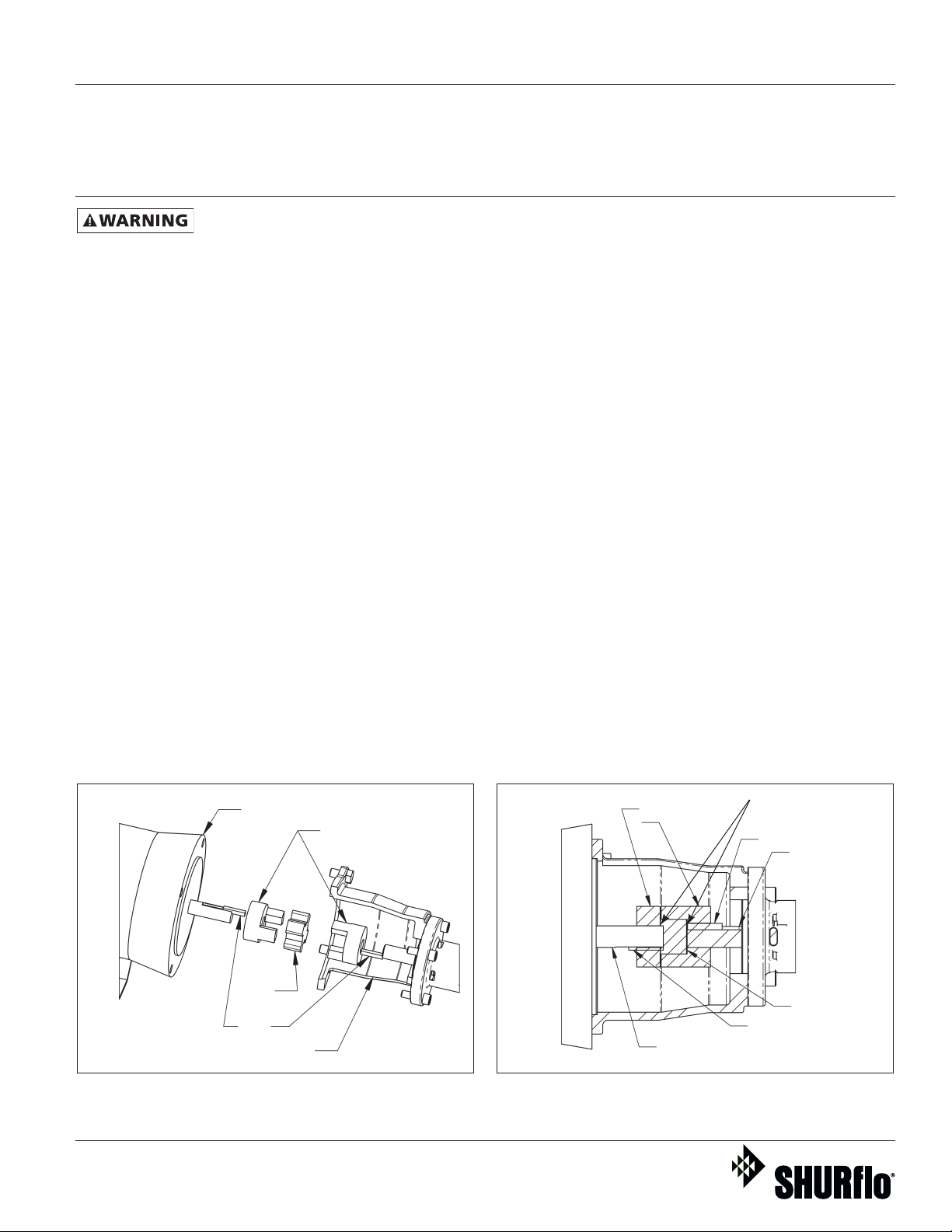
If a pump head needs to be coupled to
an electric motor, then the following
procedure should be followed. (See
Figures 3 and 4.) First, install one of
the two coupling halves and key on
the pump shaft and tighten the set
screw. The shaft end should be even or
slightly recessed from the coupling half
(approximately 1/8”). The other
coupling half must be installed on the
motor shaft. To do this, it should be
placed on the shaft with the key,
with the shaft recessed approximately
1/2”. The set screw is not yet tight-
ened. It is necessary to establish a gap
between the coupling halves of
approximately .02” to .05” (See Figure
4). A thin piece of cardboard or a piece
of paper folded up will work fine to set
this gap. The pump is placed into position on the motor and the position of
the motor coupling half is established
using the piece of thin cardboard or
other gauge material. The motor
coupling half is tightened. The pump
is removed, the coupling spider (rubber
piece) is placed into position, and the
pump bolted to the motor using the
four bolts.
Motor
Coupling Half
Spider
Key
Cutaway of Pump End
Figure 3 - Pump Motor Assembly Figure 4 - Assembly Coupler
Coupling Halves
Form L-4089 (2/17)
7
Coupler Gap
Key
Pump Shaft
Spider
Key
Motor Shaft
Page 8
SHURflo Operating Instructions, Performance,
Specifications and Parts Manual
Viton Models GMSV2A, GMSV4A, GMSV6C, GMSV2A3T, GMSV2A33T,
®
Teflon
GMSV4A5T, GMSV4A53T, GMSV6C7T and GMSV6C73T
Models GMST2A, GMST4A, GMST6C, GMST2A3T, GMST2A33T,
GMST4A5T, GMST4A53T, GMST6C7T and GMST6C73T
SHURflo 316 Stainless Steel Rotary
Close-Coupled External Gear Pumps
Installation
IMPORTANT: In any installations where
property damage and/or personal
injury can occur when the pump is
not operating due to power outages,
discharge line freezing, or any other
reason, a back-up system(s) and/or
warning system(s) should be used.
In order to safely use this product,
familiarize yourself with this pump and
also with the liquid (chemical, etc.)
that is going to be pumped through
the unit. This pump is not suitable for
many liquids.
1. Locate the pump as close to the
liquid source as possible, making
the suction line as short and direct
as possible.
PIPING
SUCTION
2. Avoid excessive lengths or number
of fittings and bends in the suction
line.
3. Attach suction line to suction inlet
(See Figure 1 for proper rotation).
4. It is recommended that same size
pipe as pump ports be used or, in
cases requiring lengthy piping, the
next larger size pipe be used.
5. If suction lift is greater than what is
indicated in the performance chart,
attach a foot valve below liquid
level at end of suction line to ensure
positive priming. Also note: If fluid
specific gravity is greater than 1.4 or
viscosity greater
than 500 SSU, a foot valve is also
recommended.
NOTE: If a foot valve (or check valve) is
not used in the suction line, it may be
necessary to refill the pump every time
the unit is stopped and you wish to restart
the pump. This depends on the length of
time between starts and whether or not
the gears are wet enough to close cavities
to affect a prime.
6. If solid contaminates are suspected
in a liquid, place a filter in the
suction line.
7. Be certain all suction piping connections are airtight.
NOTE: Assure airtight pipe connections
with the use of a pipe joint sealant.
DISCHARGE
8. Attach discharge piping to the
discharge outlet.
Support pump and
piping during assembly
and after installation.
Failure to do so may cause piping to break,
pump to fail, motor bearing failures, etc., all
of which can result in property damage and/
or personal injury.
NOTE: Should the pump need to be
self-draining, the pump head should be
mounted in the vertical position with
the suction port facing down. When
pumping high viscosity fluids, the
vertical position can be used with the
suction port facing up and the pump
mounted under the source. Increasing
the suction pipe size and eliminating
bends and elbows also assists in pumping high viscosity fluids. Max. viscosity is
500 SSU at 1725 RPM.
9. If a shut-off valve or handgun is
required in discharge line, provide
a pressure relief valve for pump
protection.
Shutting off
discharge without
providing pressure
relief can cause extreme overpressure which
can result in pump and/or motor failure. Do
not exceed 125 PSI pump or system pressure.
10. Operation under shut-off discharge
conditions will overheat and
damage pump.
NOTE: Globe valve or other restrictive
valves should not be used as shut-off
mechanism as they are restrictive in
nature and will seriously affect pump
performance.
11. After all piping and controls (not
supplied with unit) have been
installed, unit is ready for operation.
Operation
Do not run pump
dry, as permanent
damage to the pump
gears, seal, and
bearings will result. Suction pressure should
never be greater than the discharge pressure.
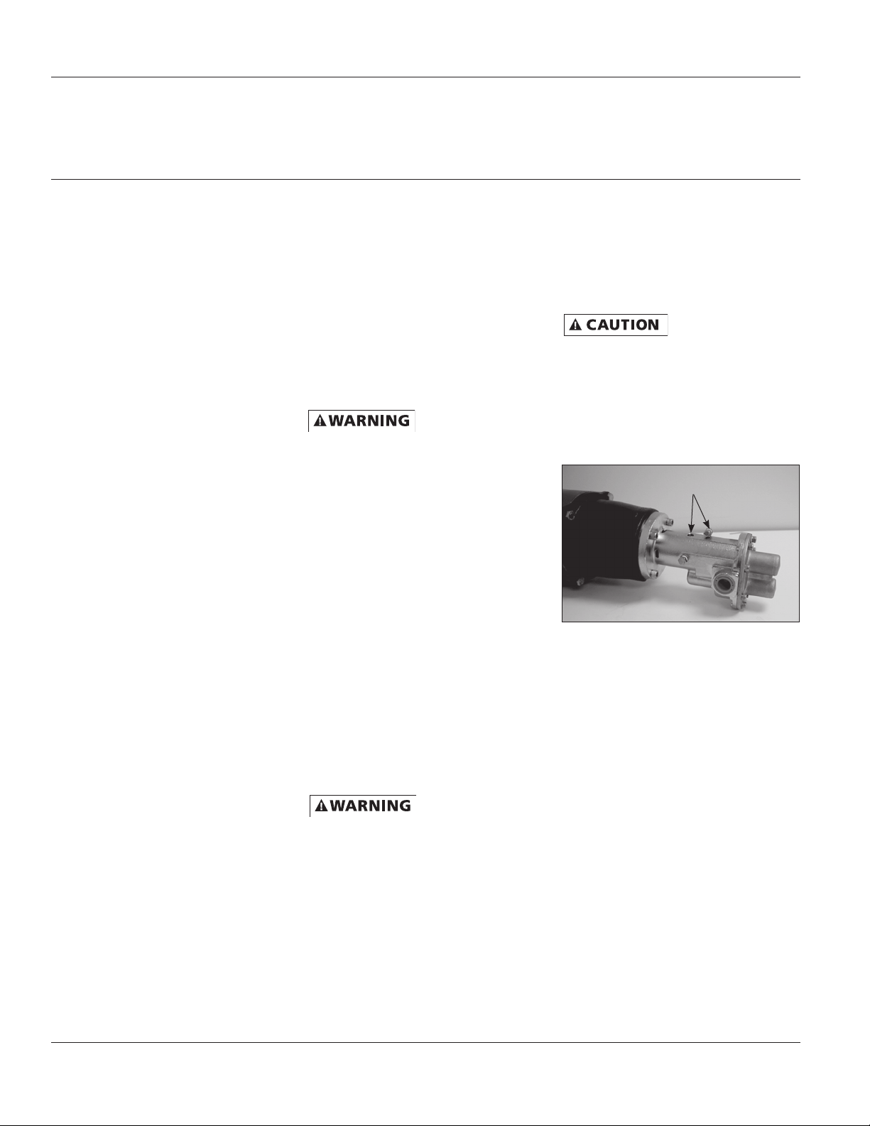
1. All pumps must be primed before
start-up and the seal chamber needs
Remove plug and fill seal chamber
with fluid and reinstall plug
Figure 5 - Prime Plug
to be filled (See Figure 5). Never
operate a pump unless it is secured
to a solid foundation and all safety
shields are installed.
Upon start-up, maintain a minimum
of 15 PSI (1 BAR) operating pressure
on the pump. This will allow any
remaining air to be driven from the
seal chamber and will ensure liquid
circulation to the mechanical seal.
2. Gear pumps are built to very close
tolerances and this tolerance must
not be altered. The liquids must,
therefore, be free of all abrasives.
Sand, silt, wettable powders, etc.
must be avoided.
3. When pumping a more viscous
(beyond 500 SSU) liquid; a slower
speed, a larger pipe size pump,
and possibly a larger motor should
be selected.
Form L-4089 (2/17)
8
Page 9
SHURflo Operating Instructions, Performance,
Specifications and Parts Manual
Viton Models GMSV2A, GMSV4A, GMSV6C, GMSV2A3T, GMSV2A33T,
GMSV4A5T, GMSV4A53T, GMSV6C7T and GMSV6C73T
Teflon® Models GMST2A, GMST4A, GMST6C, GMST2A3T, GMST2A33T,
GMST4A5T, GMST4A53T, GMST6C7T and GMST6C73T
NOTE: See performance chart for Max.
Torque.
4. Recheck motor and pump rotation.
Pump rotation is by-directional
(See Figure 1).
PRESSURE RELIEF VALVE
5. Standard models do not include a
pressure relief valve. If discharge
is going to be shut off, an external pressure relief valve should be
installed.
GEAR PUMP GASKET ADJUSTMENT
FOR TEMPERATURE (See Appendix 1)
6. For operation in fluid temperatures
above 120° F, stainless steel pump
models must have the gasket thickness adjusted. Use Appendix 1 to
identify pump, temperature and
gasket recommendations for adjusting the cover clearance prior to
operation in elevated temperatures
or viscosities above 500 SSU.
Failure to adjust pump
cover clearances for
operating temperatures above 120° F. will result in severe
pump and/or motor damage.
NOTE: When pumping fluids of high
viscosity (>500 ssu), the required torque
and HP can be reduced by adding a
gasket for increased gear clearance.
MECHANICAL SEAL FLUSH
INSTALLATION OPTIONS
7. These stainless steel pumps are
equipped with mechanical seals and
have been designed with flush ports
because mechanical seals require
cooling lubrication for long life.
a. For fluids with viscosities less than
2000 SSU, a flush is not necessary,
but the seal cavity must be prefilled with either the operating
fluid or a neutral fluid. This is to
ensure seal cooling and lubrication
during start-up (See Figure 5).
Failure to provide
initial seal prime can
result in the mechanical seal overheating with resulting repair
costs.
b. For high viscosity fluids, a flush
will be necessary. The seal must
be cooled and lubricated by a
fluid. In the case of high viscosity
fluids, due to the precision clearances between the gear teeth and
the stainless steel body, highly
viscous fluids will not be able to
adequately relieve the air in the
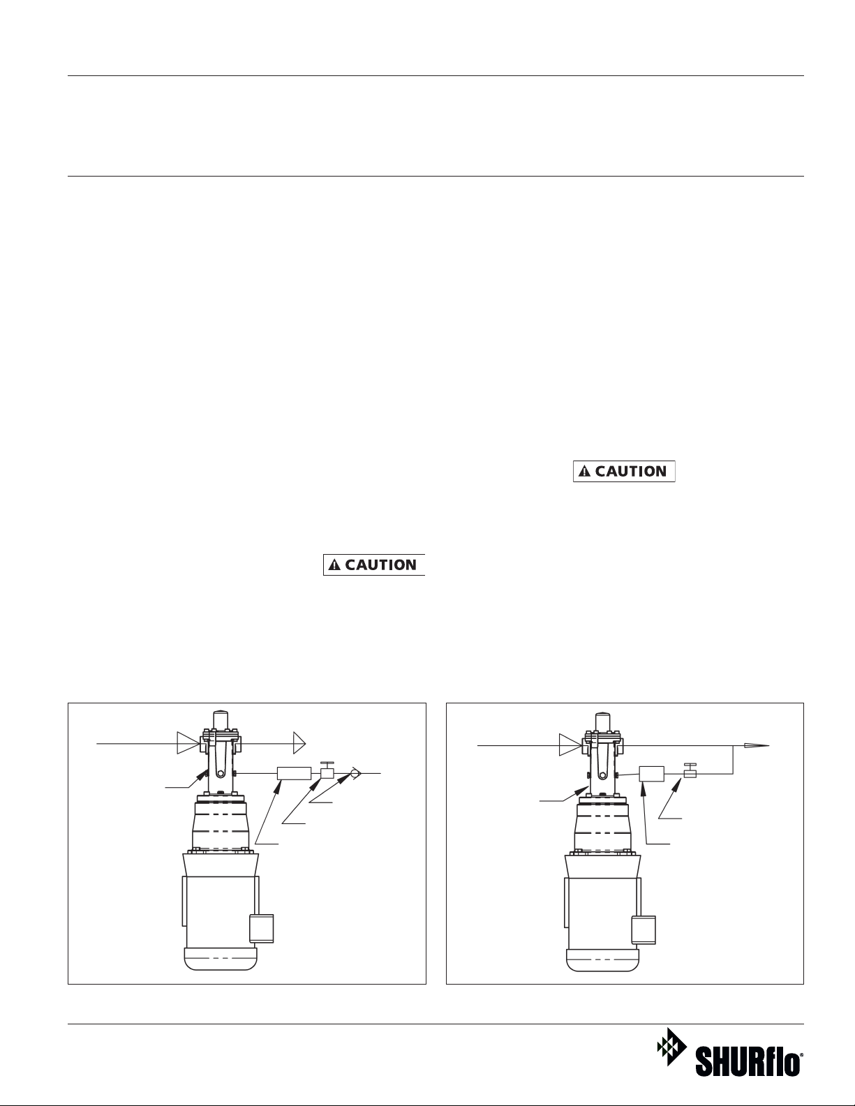
Suction
Seal Cavity
Figure 6 - External Flush
Form L-4089 (2/17)
Discharge
Flow Meter
Check Valve
Needle Valve
Suction
Seal Cavity
Figure 7 - Internal Flush
9
Discharge
Needle Valve
Flow Meter
Page 10
SHURflo Operating Instructions, Performance,
Specifications and Parts Manual
Viton Models GMSV2A, GMSV4A, GMSV6C, GMSV2A3T, GMSV2A33T,
®
Teflon
GMSV4A5T, GMSV4A53T, GMSV6C7T and GMSV6C73T
Models GMST2A, GMST4A, GMST6C, GMST2A3T, GMST2A33T,
GMST4A5T, GMST4A53T, GMST6C7T and GMST6C73T
SHURflo 316 Stainless Steel Rotary
Close-Coupled External Gear Pumps
seal cavity on start-up. The dry running of a mechanical seal
will cause rapid failure. A flush
must be provided for fluids with a
viscosity of greater than 2000 SSU.
Pumping fluids with
viscosities greater than
2000 SSU requires
flushing the seal chamber during operation,
otherwise seal damage
will occur.
EXTERNAL FLUSH
An external flush system is typically
recommended for applications where
crystallization build-up on the seal is
possible. Some dilution of the working
material must be acceptable to use an
external flush system.
The external flush system (See Figure
6 for typical installation) is commonly
used with liquids where city water can
be used as the neutral flush fluid. City
water is taken from an external source
such as a tap, hose, or special plumbing
fixture and is regulated into the seal
cavity by means of a needle valve and
flow meter. Use of an anti-siphon check
valve is required.
Operation (Continued)
It is essential that an
anti-siphon check
valve be installed
between the pump and the city water supply to prevent any back flow from possibly
contaminating the city water supply. Failure
to do so could result in contamination of the
water supply with consequential damages.
Manufacturer assumes no responsibility for
failure of user in not providing safeguards to
city water systems.
Step 1: Locate appropriate city water supply and install anti-siphon check valve.
Step 2: Use appropriate pipe nipple to
reduce piping to 1/8”.
Step 3: Install appropriate needle valve
and flow meter.
Step 4: Connect piping to one of three
available seal flush ports on pump.
Step 5: Adjust needle valve to achieve
desired flow to seal cavity (recommended 1 to 3 GPH).
INTERNAL FLUSH
Similar to above but internal supply
(See Figure 7 for typical installation).
Typically recommended for high viscosity applications ensuring lubrication to
the mechanical seal.
In an internal flush system, the fluid is
taken from the discharge and regulated from 1 to 3 GPH (Gallons Per Hour)
to the seal cavity by means of a flow
meter and needle valve.
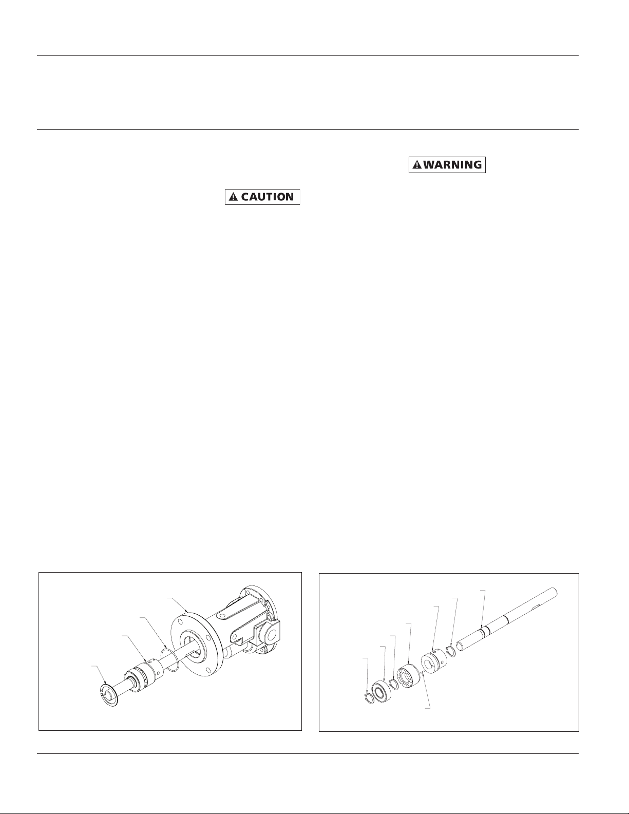
Gear Pump Body
O-ring
Shaft, Seal,
Bearing Assembly
Retaining
Ring
Figure 8 - Shaft, Seal and Bearing Assembly
Form L-4089 (2/17)
Retaining Ring
Mechanical Seal
Seal Seat Retainer
Retaining Ring
Bearing
Retaining
Ring
Seal
Retaining Pin
Figure 9 - Shaft, Seal and Bearing Assembly (detailed view)
10
Shaft
Page 11
SHURflo Operating Instructions, Performance,
Specifications and Parts Manual
Viton Models GMSV2A, GMSV4A, GMSV6C, GMSV2A3T, GMSV2A33T,
GMSV4A5T, GMSV4A53T, GMSV6C7T and GMSV6C73T
Teflon® Models GMST2A, GMST4A, GMST6C, GMST2A3T, GMST2A33T,
GMST4A5T, GMST4A53T, GMST6C7T and GMST6C73T
Step 1: Select a T pipe coupling that is
consistent with discharge pipe size and
material. Couple to discharge piping.
Step 2: From this coupling, attach a
needle valve with appropriate nipple,
reducing to 1/8” pipe or tube. Install
appropriate flow meter.
Step 3: Connect 1/8” pipe or tube to
one of three available seal cavity flush
ports.
Step 4: Adjust needle valve to desired
flow into seal cavity (recommended
1 to 3 GPH).
For alternate flush
systems for hazardous
fluid applications, hot
liquid transfer, and those not addressed in
this booklet, consult a qualified fluid handling specialist for
assistance in specifying and installing flush
systems according to local, state and federal
environmental laws.
GEAR SPEED REDUCER OPTIONS
A gear reducer can be directly mounted
between a standard pump and motor
combination. Gear speed reducers are
available for applications with high
specific gravity, or when viscosities are
greater than 500 SSU, using a standard
1725 RPM motor (See Appendix 2). The
pump relationship between volume
(GPM), pressure (PSI), speed (RPM),
viscosity, specific gravity and horsepower is shown on performance chart in
Shurflo Motor Manual form L-4082.
8. Unit is ready for operation.
Maintenance
Make certain that the
power source is
disconnected before
attempting to service
or disassemble any components!
If the power disconnect is out of sight, lock
it in the open position and tag to prevent
application of power.
CLEANING
Clean the suction line filter at regular
intervals.
ELECTRIC MOTOR
Properly selected and installed, electric motors are capable of operating
for years with minimal maintenance.
Periodically clean dirt accumulations
from open-type motors, especially in
and around vent openings, preferably
by vacuuming (avoid imbedding dirt in
windings). Oil and maintain as recommended by motor manufacturer.
GENERAL
Check the pump to motor shaft coupler
alignment at regular intervals.
Periodically check that electrical connections are tight. Pump should be drained
if placed in an area that is subject to
freezing temperatures and should not
be operated until temperature permits.
To store the pump, place a small quan-
tity of light oil or some other storage
preservative compatible with your application in the pump and rotate the shaft
very slowly to work the oil throughout
the gears and the body.
PUMP REPAIR
DISASSEMBLY
(Refer to Figure 13 for Reference
Numbers and Figures 3, 8, 9, 10, 11 & 12
for detailed seal and shaft assemblies.)
1. Remove pump from motor.
a. Remove the coupler half from the
pump (See Figure 3). The motor
coupler half does not need to be
removed unless motor is being
replaced.
2. Gear Removal
a. Remove cover plate (Ref. No. 2)
(held by eight screws) and gasket
(Ref. No. 3) if needed. Gently tap
cover plate with rubber mallet
to free it from dowel pins. Once
cover is removed, the idler shaft
and gear assembly can be pulled
out of pump body (Ref. No. 12).
b. Remove the idler gear (Ref. No.
6) from the shaft (Ref. No. 7) by
removing retaining rings (Ref.
No. 5), then slide gears off the
shaft end.
c. The drive gear (Ref. No. 6) can
be pulled out. Before drive shaft
(Ref. No. 9) can be removed
from body (Ref. No. 12), remove
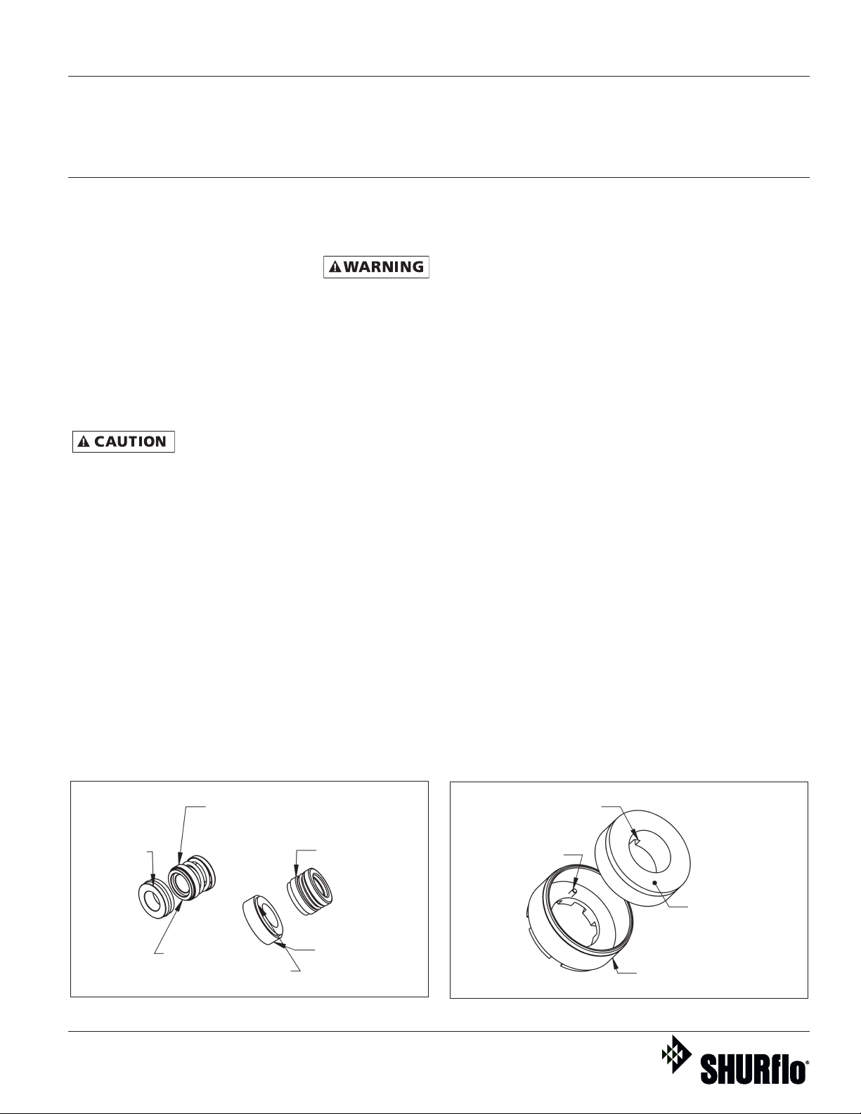
Mechanical Seal with
Seal, Spring & Retainer
(three loose pieces)
Ceramic Seat
with O-ring
Polished Face
always goes against
Carbon Face of seal
Figure 10 - Seal Types and Parts Identification
Form L-4089 (2/17)
One-piece
Mechanical Seal
with Thru Boot
Ceramic Seat
with Rubber Cup
Notch in seat
aligned with pin
Anti-Rotation
Spring Pin
(Teflon Seals Only)
Seal Seat
(Ref. 14)
Seat Retainer
(Ref. 15)
Figure 11 - Seal Seat and Retainer Assembly
11
Page 12
SHURflo Operating Instructions, Performance,
Specifications and Parts Manual
Viton Models GMSV2A, GMSV4A, GMSV6C, GMSV2A3T, GMSV2A33T,
®
Teflon
GMSV4A5T, GMSV4A53T, GMSV6C7T and GMSV6C73T
Models GMST2A, GMST4A, GMST6C, GMST2A3T, GMST2A33T,
GMST4A5T, GMST4A53T, GMST6C7T and GMST6C73T
SHURflo 316 Stainless Steel Rotary
Close-Coupled External Gear Pumps
woodruff key (Ref. No. 8) by
gently tapping key with drift pin.
(Do not damage key or keyway
upon removal.)
3. From the drive shaft end of the gear
pump, remove the internal snap
ring (Ref. No. 13) from the body
(Ref. No. 12). The drive assembly,
which consists of the drive shaft
(Ref. No. 9), seal assembly (Ref. Nos.
18 & 19), seat retainer (Ref. No. 16),
bearing (Ref. No. 15) and retaining rings (Ref. No. 14), can now be
removed from the unit (See Figure
8). Also remove the internal o-ring
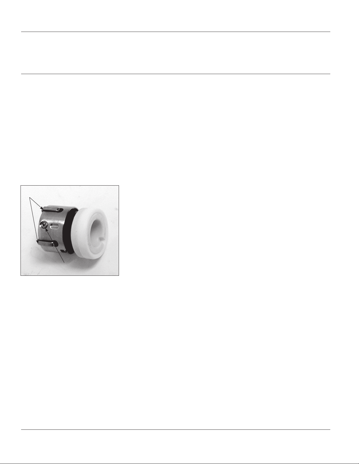
“C” Clips (4)
Remove after set screws
are tight on shaft
Set screws (2)
Figure 12 - Teflon Seal and Seat
(Ref. No. 20) from the body.
REASSEMBLY
(Refer to Figure 13 for Reference
Numbers and Figures 3, 8, 9, 10, 11 &
12 for detailed seal and shaft assemblies.)
1. Shaft/Seal Assembly
a. Install inside o-ring (Ref. No. 20)
into body (Ref. No. 11). Lubricate
with water.
b. There are two possible standard
types of seals. One style, the seal
is one piece while the other style
has a seal boot, spring and spring
retainer. The seal seats can also
be of two styles; one has a rubber
boot and the other has an o-ring.
Identify which type you have
(See Figure 10). (For the Teflon
seal, see the following note and
Figure 12.)
c. Refer to assembling components
on drive shaft (See Figure 9).
When installing the seal on the
shaft, wet with water and be
cautious when sliding it into
position. The spring retaining
washer and spring are behind
the seal with the carbon ceramic
facing towards the keyed end of
drive shaft (See Figure 9).
d. Press seal seat into the seal
retainer (See Figure 11) using
water as a lubricant. The white
shiny ceramic face should be
visible after pressing the seal
into the seal retainer. It is recommended to use a cardboard washer or wood dowel when pushing
the seal seat into the seal seat
retainer. Any scratches, dirt, or
fingerprints on the carbon ceramic
faces will cause the seal to leak.
The seal seat is stationary in the
pump, while the seal on the
shaft rotates, providing for the
sealing surface.
NOTE: When installing the seat for the
Teflon seal, an anti-rotation pin must be
installed into the seat retainer. The
anti-rotation pin (Ref. No. 25) is a small
spring pin which must be installed into
the seat retainer in the small hole.
About 1/8” to 3/16” of the pin should
be exposed inside of the seat retainer (Figure 11). The seal seat is then
installed into the seat retainer.
®
Form L-4089 (2/17)
12
Page 13
SHURflo Operating Instructions, Performance,
Specifications and Parts Manual
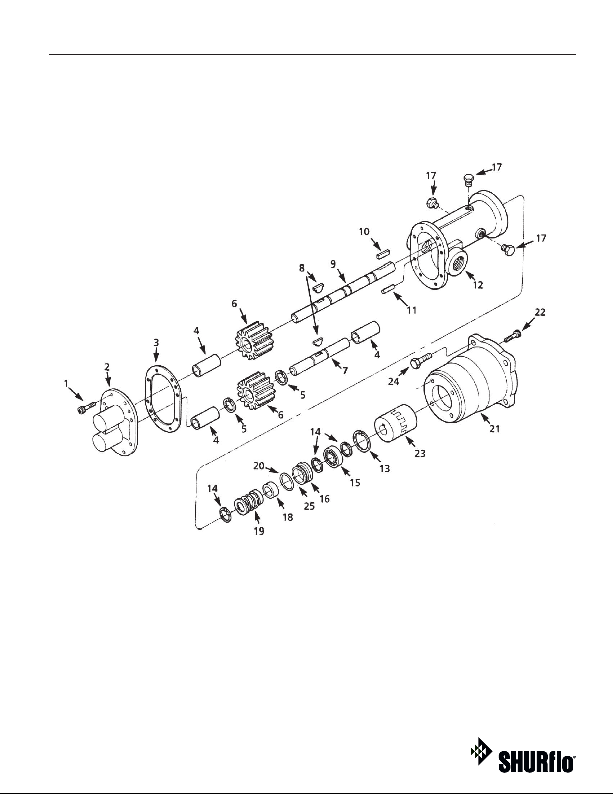
To order parts, contact a SHURflo Distributor or Order Direct.
Distributors can be found at www.shurfloindustrial.com.
Please provide following information:
-Model number
-Serial number (if any)
-Part description and number
as shown in parts list
Figure 13 – Repair Parts Illustration
Form L-4089 (2/17)
13
Page 14
Viton Models GMSV2A, GMSV4A, GMSV6C, GMSV2A3T, GMSV2A33T,
GMSV4A5T, GMSV4A53T, GMSV6C7T and GMSV6C73T
Models GMST2A, GMST4A, GMST6C, GMST2A3T, GMST2A33T,
GMST4A5T, GMST4A53T, GMST6C7T and GMST6C73T
SHURflo Operating Instructions, Performance,
Specifications and Parts Manual
Teflon
®
SHURflo 316 Stainless Steel Rotary
Close-Coupled External Gear Pumps
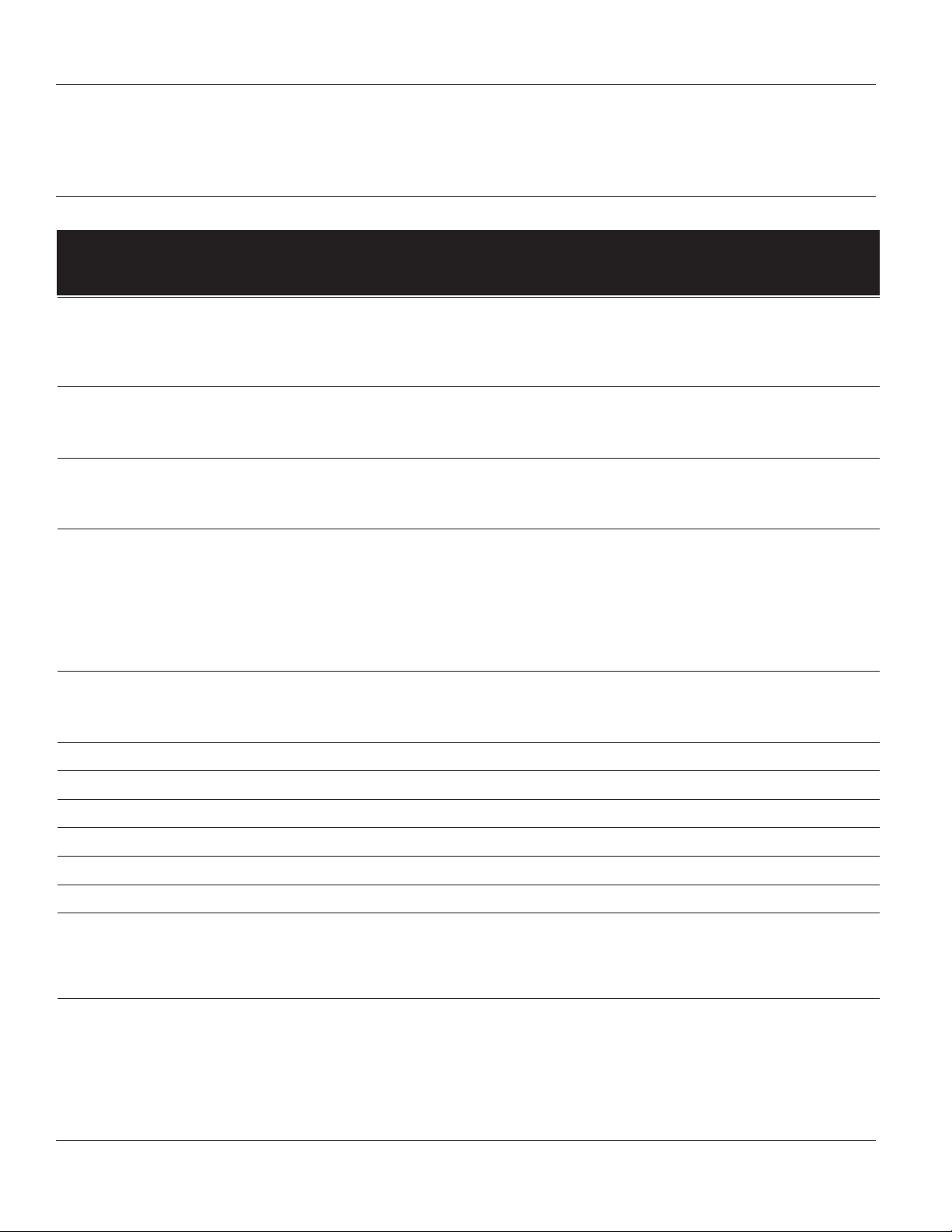
Repair Parts List
GMSV2A† GMSV4A† GMSV6C† GMST2A† GMST4A† GMST6C†
Included GMSV2A3T GMSV4A5T GMSV6C7T GMST2A3T GMST4A5T GMST6C7T
Ref. No. In Kit Description GMSV2A33T GMSV4A53T GMSV6C73T GMST2A33T GMST4A53T GMST6C73T Qty.
1 Soc. Hd. Screw 19888 19888 19888 19888 19888 19888 8
2 Cover - 316 SS*** 21870S 21871S 21872S 21870S 21871S 21872S 1
3 1 Gasket - Graphoil 22115 22116 19931 22115 22116 19931 1
Optional High Temperature Gasket Kit 24436 23956 23982 24436 23956 23982
4 Bushing - Carbon Graphite 21222 21223 21179 21222 21223 21179 3
5 1, 2 Ext. Ret. Ring 21094 12840 21063 21094 12840 21063 2
6 1, 2, 3, 4 Gear - Ryton PPS 13879 12764 13883 13879 12764 13883 2
7 2 Idler Shaft - 316 SS 21876 21877 21878 21876 21877 21878 1
8 1, 2, 3,4 Woodruff Key - 316 SS 21301 12841 12841 21301 12841 12841 2
9 3, 4 Drive Shaft - 316 SS 21873 21874 21875 21873 21874 21875 1
10 3, 4 Square Key - 316 SS 21436 21437 22428 21436 21437 22428 1
11 Dowel Pin - 316 SS 21056 21056 21056 21056 21056 21056 2
12 Body - 316 SS*** 21867S 21868S 21869S 21867S 21868S 21869S 1
13 3, 4 Int. Ret. Ring 04303 04259 19942 04303 04259 19942 1
14 3, 4 Ext. Ret. Ring 21093 12582 15952 21093 12582 15952 3
15 3, 4 Ball Bearing 04306 04257 19988 04306 04257 19988 1
16 3, 4 Retainer - 316 SS 21969 21968 22144 21969 21968 22144 1
17 Pipe Plug - 316 SS 24441 24441 24441 24441 24441 24441 3
*18/19 3, 4 Mech. Seal/Seal Seat (Std.) 24766S 24767S 24768S 24612S 24613S 24614S 1
Optional Mech. Seal/Seal Seat (Viton) Std. Std. Std. 24766S 24767S 24768S
**Optional Mech. Seal/Seal Seat (Teflon
®
) 24612S 24613S 24614S Std. Std. Std.
Optional Mech. Seal/Seal Seat (Buna) 24604S 24605S 24606S 24604S 24605S 24606S
20 3, 4 O-Ring (Std.) 22173 22174 22343 22191 22192 22193 1
Optional O-Ring (Viton) Std. Std. Std. 22173 22174 22343
Optional O-Ring (Teflon®) 22191 22192 22193 Std. Std. Std.
Optional O-Ring (Buna) 21303 21913 23447 21303 21913 23447
21 Adapter - Cast Iron 21866 21866 21979 21866 21866 21979 1
22 Soc. Hd. Bolt 22362 22362 22362 22362 22362 22362 4
23 Coupling 21885 21886 22184 21885 21886 22184 1
24 Cap Screw 13309 13309 13309 13309 13309 13309 4
**25 Anti-Rotation Pin NA NA NA 22537 22537 22537 1
26 Motor (3/4 HP,1 PH TEFC) 21594S Optional Optional 21594S Optional Optional 1
(For Pump Model GMSV2A3T)
27 Motor (3/4 HP, 3 PH TEFC) 22146S Optional Optional 22146S Optional Optional 1
(For Pump Model GMSV2A33T)
28 Motor (1-1/2 HP,1 PH TEFC) Optional 21596S Optional Optional 21596S Optional 1
(For Pump Model GMSV4A5T)
29 Motor (1-1/2 HP, 3 PH TEFC) Optional 22148S Optional Optional 22148S Optional 1
(For Pump Model GMSV4A53T)
30 Motor (3 HP,1 PH TEFC) Optional Optional 24646S Optional Optional 24646S 1
(For Pump Model GMSV6C7T)
31 Motor (3 HP, 3 PH TEFC) Optional Optional 22150S Optional Optional 22150S 1
(For Pump Model GMSV6C73T)
3, 5, 6, 8 Kit 1 - Gear Repair Kit 22278 22279 22280 22278 22279 22280
5, 6, 7, 8 Kit 2 - Idler Shaft/Gear Assy. Kit 22437 22438 22439 22437 22438 22439
6, 8, 9,10,13,14, Kit 3 - Dr. Shaft/Gear Assy. Kit 22303V 22304V 22305V 22303T 22304T 22305T
15,16,18/19,20 (Viton or Teflon®)
6, 8, 9,10,13,14, Kit 4 - Dr. Shaft/Gear Assy. Kit (Buna) 22303B 22304B 22305B 22303B 22304B 22305B
15,16,18/19,20
NOTE: For operating temperatures greater than 120° F. or high viscosities, gasket thickness must be adjusted.
(†) Pump head only (no motor).
(*) Mech. seal and seat sold as set only (Ref. Nos. 18 & 19). Teflon
(**) When ordering the Teflon
(***) Body and cover supplied with carbon graphite bushings installed.
When converting to a different seal/seat material, remember to order the o-ring (Ref. No. 20) of the same material.
SS = Stainless Steel
Ryton = PPS (Polyphenylene Sulfide)
TEFC = Totally-Enclosed Fan-Cooled Motor
Kits 2 - 4 do not ship with gaskets.
®
seal, Teflon® Seal Anti-Rotation Pin is required (Ref. No. 25).
Part No. for Viton Pump Models Part No. for Teflon Pump Models
®
and Viton seals consist of carbon ceramic faces with 316 SS components.
Form L-4089 (2/17)
14
Page 15
SHURflo Operating Instructions, Performance,
Specifications and Parts Manual
Viton Models GMSV2A, GMSV4A, GMSV6C, GMSV2A3T, GMSV2A33T,
GMSV4A5T, GMSV4A53T, GMSV6C7T and GMSV6C73T
Teflon® Models GMST2A, GMST4A, GMST6C, GMST2A3T, GMST2A33T,
GMST4A5T, GMST4A53T, GMST6C7T and GMST6C73T
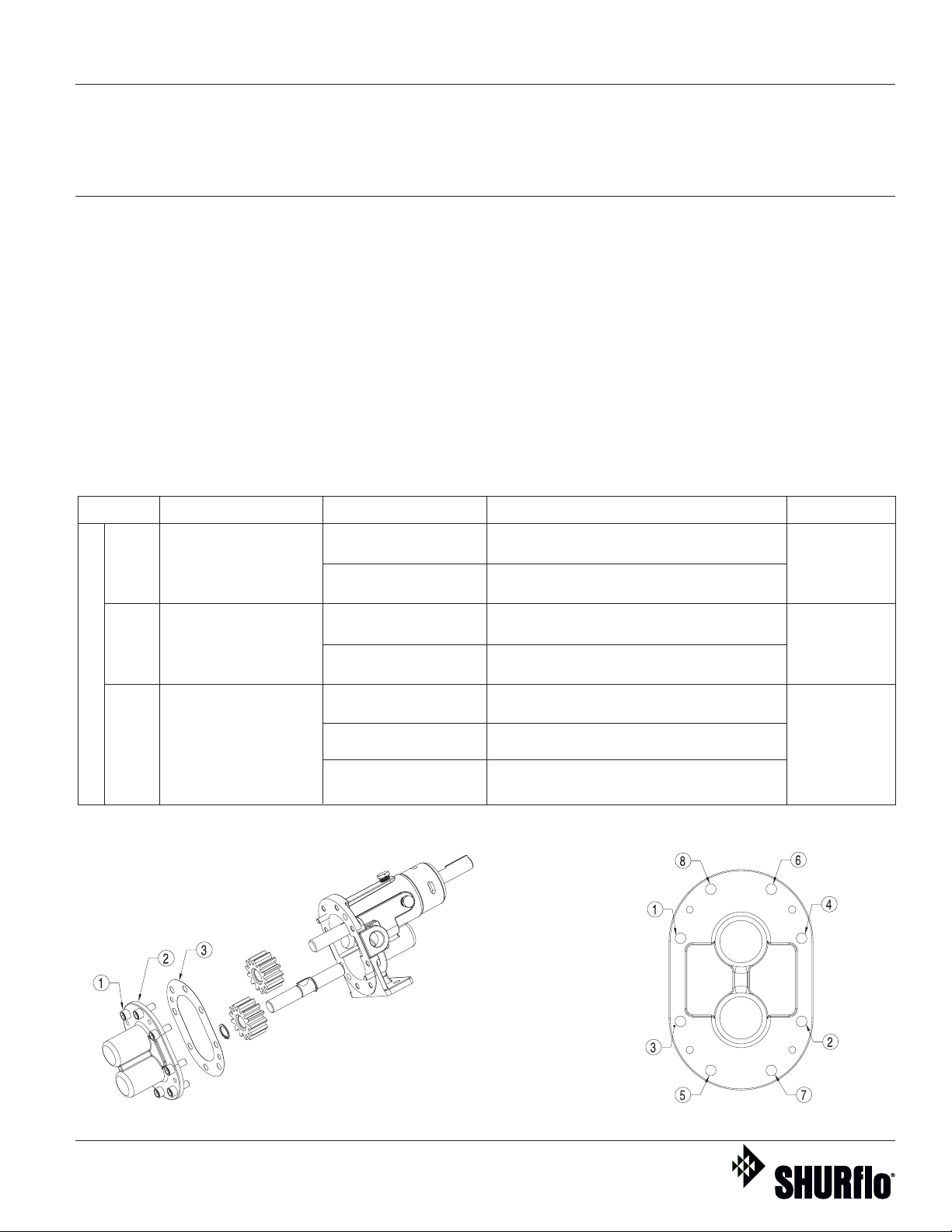
Appendix 1 - Gear Pump Gasket Adjustment for Temperature
Gear pump is factory assembled to
operate within a temperature range
of 70° – 120° F (20° – 50° C). For
temperatures outside this range,
please see the table below for your
series and port size pump.
NOTE: Always refer to the original
owner’s manual repair and maintenance sections on pump disassembly and assembly for more detailed
instructions.
NOTE: When pumping fluids of high
viscosity (>500 SSU), the required torque
and HP can be reduced by adding a
gasket for increased gear clearance.
Gasket Installation Instructions (refer
to assembly diagram below):
1. Turn off power to pump, turn off
inlet and outlet valves, and relieve
pressure in lines.
2. Allow pump to cool.
3. Remove cover screws (1), cover (2)
and gasket (3). Be sure to mark
proper orientation of cover and
pump body.
4. Replace gaskets (3) per instructions
listed in table.
5. Replace cover (2) and cover screws
(1) according to orientation marked
in step 3.
6. Tighten cover screws (1) in
sequence listed on diagram. Use
torque specifications listed in table.
Kit PN NPT Port Size Temp Range Instructions Bolt Torque
24436
Pumps with 3/8”ports
23956
Pumps with 1/2”ports
23982
Stainless Steel Gear Pump Series
Pumps with 1”ports
Up to 120° F
(50° C)
120° F – 280° F
(50° C – 138° C)
Up to 120° F
(50° C)
120° F – 280° F
(50° C – 138° C)
Up to 70° F
(20° C)
70° F – 120° F
(20° C – 50° C)
120° F – 280° F
(50° C – 138° C)
Use standard graphoil gasket as
shipped (0.010” thick)*
Use optional thicker (0.015”) graphoil
gasket
Use standard graphoil gasket as
shipped (0.010” thick)*
Use optional thicker (0.015”) graphoil
gasket
Use optional thinner (0.010”) graphoil
gasket
Use standard graphoil gasket as
shipped (0.015” thick)*
Use 2X optional thinner (for a total of
0.020”) graphoil gasket
75 in.-lbs.
(8.5 N-m)
75 in.-lbs.
(8.5 N-m)
75 in.-lbs.
(8.5 N-m)
Gear Pump
Gasket Install
Assembly
Form L-4089 (2/17)
*Standard Set-up
Bolt
Tightening
Sequence
15
Page 16
SHURflo Operating Instructions, Performance,
Specifications and Parts Manual
Viton Models GMSV2A, GMSV4A, GMSV6C, GMSV2A3T, GMSV2A33T,
®
Teflon
GMSV4A5T, GMSV4A53T, GMSV6C7T and GMSV6C73T
Models GMST2A, GMST4A, GMST6C, GMST2A3T, GMST2A33T,
GMST4A5T, GMST4A53T, GMST6C7T and GMST6C73T
SHURflo 316 Stainless Steel Rotary
Close-Coupled External Gear Pumps
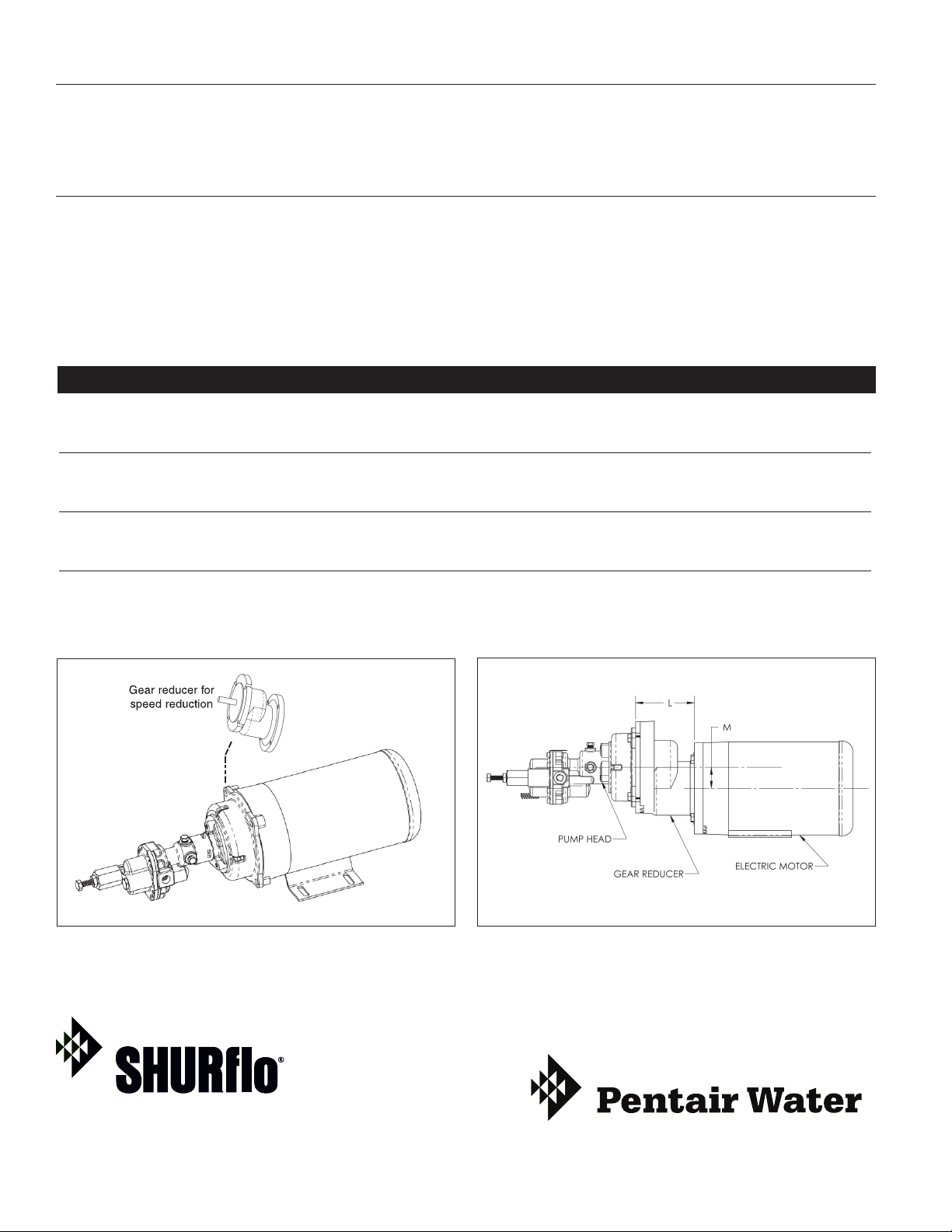
Appendix 2 - Optional C-Flanged Pump Speed Gear Reducers
GEAR SPEED REDUCER OPTIONS
A gear reducer can be directly mounted
between a standard pump and motor
combination. Gear speed reducers are
available for applications with high
Model Number Description L* M* RPM Out** Ship Weight (Ibs.)
AGR56C600 Gear Reducer, 56C to 56C, 3.0 ratio 5.177 1.675 583 21
AGR56C900 Gear Reducer, 56C to 56C, 2.0 ratio 5.177 1.675 875 21
AGR56C1200 Gear Reducer, 56C to 56C, 1.5 ratio 5.177 1.675 1167 21
AGR145TC600 Gear Reducer, 145TC to 145TC, 3.0 ratio 5.625 2.875 583 29
AGR145TC900 Gear Reducer, 145TC to 145TC, 2.0 ratio 5.625 2.875 875 29
AGR145TC1200 Gear Reducer, 145TC to 145TC, 1.5 ratio 5.625 2.875 1167 29
AGR184TC600 Gear Reducer, 184TC to 184TC, 3.0 ratio 7.43 2.875 583 56
AGR184TC900 Gear Reducer, 184TC to 184TC, 2.0 ratio 7.43 2.875 875 56
AGR184TC1200 Gear Reducer, 184TC to 184TC, 1.5 ratio 7.43 2.875 1167 56
(*) L dimension (in inches) is length of the gear reducer. M dimension (in inches) is the offset of the reducer output centerline from the motor centerline. All reducers may be rotated in 90° increments, changing the orientation of the offset from top to side to bottom.
(**) Based on 1750 RPM motor speed.
specific gravity, or when viscosities are
greater than 500 SSU, using a standard
1725 RPM motor. The pump relationship between volume (GPM), pressure
(PSI), speed (RPM), viscosity, specific
gravity and horsepower is shown on
performance chart in Shurflo Motor
Manual form L-4082.
Disassemble Pump From Motor and
Insert Gear Reducer
Form L-4089 (2/17)
Printed in USA
Gear Reducer Installed between Pump and Motor
(References L and M are dimensions in chart above.)
FLOW TECHNOLOGIES GROUP
5900 Katella Ave. • Cypress, CA 90630
Phone: (800) 854-3218 • (562) 795-5200 • Fax: (562) 795-7554
www.shurfloindustrial.com
 Loading...