

Page 1
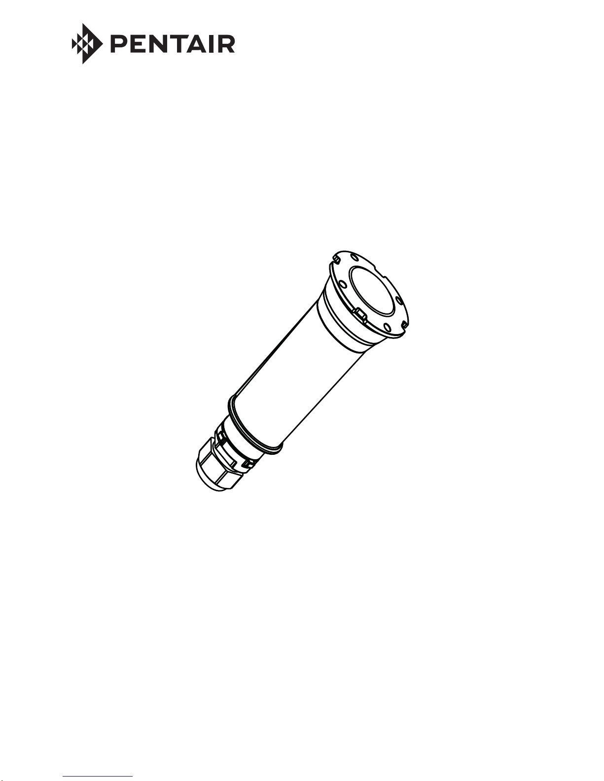
GLOBRITE™ White LED Pool/Spa Light Installation and User’s Guide
IMPORTANT SAFETY INSTRUCTIONS
READ AND FOLLOW ALL INSTRUCTIONS
SAVE THESE INSTRUCTIONS
INSTALLATION
AND
USER’S GUIDE
GLOBRITE™ WHITE LED LIGHT
FOR POOL AND SPA
Page 2
GLOBRITE™ White LED Pool /Spa Light Installation and User’s Guide
Technical Support
Phone: (800) 831-7133 - Fax: (800) 284-4151
Web sites: www.pentairpool.com and www.staritepool.com:
Contents
IMPORTANT WARNING AND SAFETY INSTRUCTIONS...................................... i-ii
GloBrite White LED Pool Light Overview ............................................................1
Operating GloBrite Lights Using a Wall Switch ................................................... 1
Using and External Transformer for Multiple 12 VAC GloBrite Lights ................ 1
Maximum Wattage Using Multiple LED Lights
(with a 300 W Transformer) .................................................................................. 1
Operating GloBrite White Lights Using a Wall Switch ........................................ 2
GloBrite Light Fixture Installation (new pool construction) ................................. 3
Installing the GloBrite Light Sleeve and Niche
(after electrical requirements are met) .................................................................. 3
Installing the GloBrite Light Sleeve and Niche in a Concrete/Gunite Pool........... 4
Option 1: Light Niche Sleeve with Cone .......................................................... 4
Option 2: Conduit to Light Niche ......................................................................5
Installing GloBrite Light in a Fiberglass Pool ........................................................ 6
Installing GloBrite Light in a Vinyl Pool..................................................................7
Installing the GloBrite Light Assembly (after niche installation) ...........................8
Replacing the GloBrite Light Assembly (in an existing pool or spa) ...................10
Replacing the GloBrite Light Assembly (after electrical
requirements are met) .......................................................................................... 11
Connecting GloBrite Lights to EasyTouch/IntelliTouch Load Center ................... 12
GloBrite
Lights Parts List and Replacement Kits ................................................. 14
THE GLOBRITE™ LED LIGHT CANNOT BE USED ON A
DIMMER CIRCUIT. USING A DIMMER CIRCUIT SWITCH
WILL RESULT IN PERMANENT DAMAGE.
P/N 620218 Rev B 2/2015
READ AND FOLLOW ALL
INSTRUCTIONS IN THIS MANUAL.
Page 3

GLOBRITE™ White LED Pool/Spa Light Installation and User’s Guide
i
Most states and local codes regulate the construction, installation, and
operation of public pools and spas, and the construction of residential
pools and spas. It is important to comply with these codes, many of which directly
regulate the installation and use of this product. Consult your local building and health
codes for more information.
SERIOUS BODILY INJURY OR DEATH CAN RESULT IF THIS LIGHT
IS NOT INSTALLED AND USED CORRECTLY.
Before installing this product, read and follow all warning notices
and instructions in this Guide. Failure to follow warnings and
instructions can result in severe injury, death, or property damage.
Call (800) 831-7133 for additional free copies of these instructions. Please refer to
www.pentair pool.com for more information related to this products.
IMPORTANT NOTICE - Attention Installer: This Installation and User’s
Guide (“Guide”) contains important information about the installation,
operation and safe use of this underwater pool and spa light. This Guide
should be given to the owner and/or operator of this equipment.
IMPORTANT WARNING AND SAFETY INSTRUCTIONS
BEFORE WORKING ON the GloBrite LED Light always disconnect
power to the pool and/or spa lights at the source circuit breaker
from the light before servicing the light. Failure to do so could
result in death or serious injury to service person, pool users or
others due to electric shock. When installing and using this
electrical equipment, basic safety precautions should always be
followed.
RISK OF ELECTRICAL SHOCK OR ELECTROCUTION:
This underwater light must be installed by a licensed or certified electrician or a
qualified pool professional in accordance with the current National Electrical Code
(NEC), NFPA 70 or the Canadian Electrical Code (CEC), CSA C22.1. All applicable
local installation codes and ordinances must also be adhered to. Improper
installation will create an electrical hazard which could result in death or serious
injury to pool users, installers or others due to electrical shock, and may also cause
damage to power source. Always disconnect the power to the pool light at the circuit
breaker before servicing the light. Failure to do so could result in death or serious
injury to service person, pool users or others due to electrical shock.
THE GLOBRITE™ UNDERW A TER LED POOL LIGHT REQUIRES HIGH
VOL T AGE WHICH CAN SHOCK, BURN, OR CAUSE DEA TH.
For countries in compliance with International Electrotechnical
Commission (IEC) regulatory standards: The light fixture must be
installed by a licensed or certified electrician or a qualified pool service person, in
accordance with current IEC 364-7-702 and all applicable local codes and ordinance.
Improper installation will create an electrical hazard, which could result in death or
serious injury to pool user, installer or other due to electrical shock and may also cause
damage to the property.
INST ALLERS, POOL OPERATORS AND POOL OWNERS MUST
READ THESE WARNINGS AND ALL INSTRUCTIONS BEFORE
USING THE POOL AND/OR SP A LIGHT.
Page 4

GLOBRITE™ White LED Pool /Spa Light Installation and User’s Guide
ii
IMPORTANT WARNING AND SAFETY INSTRUCTIONS
NOTICE: The external flexible cable or cord of this luminaire cannot be replaced; if the
cord is damaged, the luminaire must be discarded.
INSTALLERS AND INSPECTORS
THE GLOBRITE™ LED LIGHT AND PLASTIC NICHE FORM A COMPLETE NONMET ALLIC LO W VOLTAGE LIGHTING SYSTEM. THIS CONFIGURA TION DOES
NOT REQUIRE BONDING OR GROUNDING WHEN POWERED BY A LISTED 100
W ATT OR 300 WATT TRANSFORMER (LISTED ON PAGE 19) AND INSTALLED IN
COMPLIANCE WITH THE CURRENT NATIONAL ELECTRIC CODE (NEC).
UNBONDED LIGHTING NEC PROVISIONS: When the UL listed non-metallic
GloBrite LED Light low voltage lights are used with the GloBrite light approved
niches (as listed on page 19), the current NEC provides an exception to
luminaire bonding and grounding in Article 680.6 and 680.23
POOL WATER BONDING NEC PROVISIONS :For Pool W ater Bonding required by
NEC Article 680.26C, concrete pools are considered conductive (refer to 680.26
(b)(1) due to the porosity of concrete and the bonding of rebar . No additional
bonding is required.
POOL AND SP A FIXED LUMINARIES: Follow these guidelines when installing or
replacing Pentair Water P ool and Spa P ool and Spa fixed luminaries:
- FOR LIGHT OPERA TION, ONLY USE A SAFETY ISOLATION TRANSFORMER.
Note: Connect all three wires to the corresponding circuit wires in the Junction
Box (blac k wire to power, white wire to common, and green wire to ground). FIXED
POOL AND SPA LUMINARIES SPECIFICATION: 12 VAC 50/60 Hz
IMPORT ANT NO TICE:
THE GLOBRITE WHITE LED LIGHT IS A NON-SER VICEABLE LIGHT .
THE COMPLETE LIGHT ASSEMBLY MUST BE REPLA CED.
Page 5
GLOBRITE™ White LED Pool/Spa Light Installation and User’s Guide
GloBrite™ White LED Pool Light Overview
This manual describes how to install and replace the pool and spa GloBrite™ White LED
Light. The GloBrite White LED Light allows you to choose from one of three brightness
levels. For more information see page 2.
Operating GloBrite LED Lights Using a Wall Switch
The GloBrite LED light can be manually controlled using a standard wall-mount light
switch. Multiple GloBrite lights can be connected via a junction box and a 12 VAC
isolation transformer to a single switch so that all lights can be switched on and off
together. For wiring diagram, see page 13.
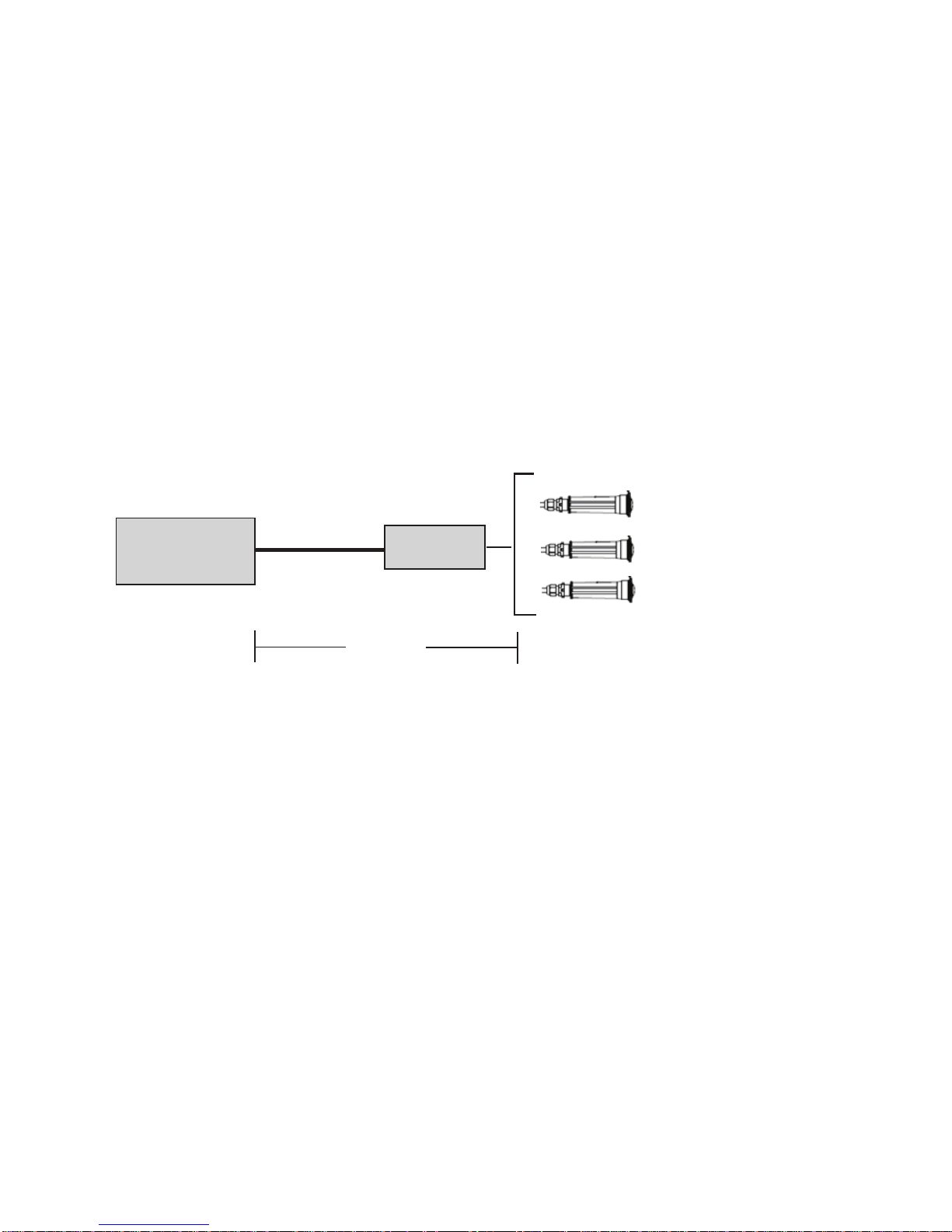
Using an External Safety Isolation Transformer for Multiple 12 VAC GloBrite
Lights
When using multiple GloBrite 12 VAC lights on a 100 Watt safety isolation transformer, it
is recommended that no more than five (5) GloBrite lights be used. For long cable
lengths with a single light, It is recommended not to exceed 150 feet (45.72 m) of total
cable run between the
12 VAC isolation transformer and the GloBrite light.
1
Note: If a longer cable run
is necessary, it is
recommended that
separate 100 Watt safety
isolation transformers be
used for each light with no
more than 150 feet of total
cable run between the
transformer and lights.
Maximum Wattage Using Multiple GloBrite White LED lights (with
a 300 Watt Isolation Transformer)
IMPORTANT! When using multiple 12 VAC Pentair® LED white pool and spa lights the
total allowable light wattage is 300 Watts maximum. The individual light wattage is as
follows:
• One GloBrite White LED Pool light is 15 Watts maximum
• One GloBrite Color LED Pool light is 15 Watts maximum
• One AmerBrite White LED (500W) pool light is 51 Watts maximum
• One AmerBrite White LED (400W) pool light is 44 Watts maximum
• One AmerBrite White LED (300W) pool light is 36 Watts maximum
• One AmerBrite Color LED pool light is 36 Watts maximum
• One IntelliBrite Color LED pool light
is 26 Watts maximum
• One IntelliBrite Color LED spa light is 18 Watts maximum
J Box
12 Gauge
(minimum)
150 ft.
100 Watt
Transformer
Page 6

GLOBRITE™ White LED Pool /Spa Light Installation and User’s Guide GLOBRITE™ White LED Pool/Spa Light Installation and User’s Guide
2
Selecting a GloBrite White Light Brightness Level using a Wall Switch
GloBrite White lights allow you to choose from one of three br ightness levels (100%,
75% and 50%). Whenever the GloBrite white light is turned on, it starts at its highest
brightness level (100%). If it has been set to the medium (75%) or low brightness level
(50%), it will turn on at 100% then step down to the correct brightness level in one or
two one (1) second steps.
To select one of the GloBrite’s three brightness levels (100%, 75% and 50%) first
power on the lights, then by rapidly cycling the light switch OFF and ON a specified
number of times, you can select the desired light brightness level.
Selecting the light’s brightness levels is as follows:
• 100% Brightness: Switching the lights OFF then rapidly back ON, will set
the lights to 100% brightness.
• 75% Brightness: Switch OFF-ON-OFF-ON and the lights will come on at
100% them dim to 75% after 1 second.
• 50% Brightness: Switch OFF-ON-OFF-ON-OFF-ON and the lights will
come on at 100%, dim to 75% after one second and then dim to 50% after
another second.
GloBrite™ White Lights can be controlled using a standard wall-mount light switch. Multiple
GloBrite white lights can be connected via a junction box and a 12 VAC transformer to a
single switch so that all lights can be switched on and off together. GloBrite White lights
are controlled by cycling AC power to the 12 VAC transformer from a standard wall switch.
By turning the switch on and off a specific number of times, you can choose from one of
three brightness levels.
Powering on the GloBrite White LED Lights
Note: The GloBrite White LED light ships from the factory in the 100% brightness
mode.
When the GloBrite White light is powered on, it defaults to the previously selected
brightness level. Note: If power to the light is off for more than five (5) seconds, the last
brightness level that was saved will be displayed.
Operating GloBrite™ White Lights Using a Wall Switch
Page 7

GLOBRITE™ White LED Pool/Spa Light Installation and User’s Guide
INSTALLING THE GLOBRITE LIGHT SLEEVE AND NICHE
(AFTER ELECTRICAL REQUIREMENTS ARE MET)
The following describes how to install the GloBrite™ Light fixture.
Be sure that the pool or spa meets the requirements of the current National Electrical
Code (N.E.C.) Article 680-22 and all local codes and ordinances. A licensed or
certified electrician must install the electrical system to meet or exceed those
requirements before the underwater light is installed. Some of the requirements of
the National Electrical Code which the pool’s electrical system must meet are as
follows:
BEFORE ST ARTING: The follo wing information describes the tasks that must
be completed by the electrician
before
the light fixture is installed. See
Figure 1 on page 6.
• The Junction Box and the low voltage transformer is located at least
4 (four) inches (10.16 cm) above ground level or eight (8) inches
(20.3 cm) above maximum water level, whichever is higher. The
Junction Box must be at least 48 inches (1.22 m) from the edge of the
pool. See Figure 1 on page 7.
• The GloBrite light niche must be properly installed so that the top edge
of the lens of the GloBrite light is at least 4 inches below (not more than
48 inches below in Canada) the surface of the water in the pool or spa.
• To be certain that the pool or spa electrical system meets all applicable
requirements, the electrician should also consult the local building
department.
GLOBRITE™ LIGHT FIXTURE INSTALLATION
(NEW POOL CONSTRUCTION)
There are three types of GloBrite LED Light niches for pool or spa:
Concrete/gunite, fiberglass or vinyl liner.
Note: The GloBrite light niche must be installed in or on the wall of the pool (or
water feature) with the top of the lens not less than 4 inches (10.2 cm) below the
normal water level of the pool. The GloBrite light can also be installed in the
bottom of the pool (facing up).
3
Page 8

GLOBRITE™ White LED Pool /Spa Light Installation and User’s Guide
Installing GloBrite™ Light Sleeve and Niche in a
Concrete/Gunite Pool - Option 1 and Option 2 (see page 5)
Option 1: Niche Sleeve with Cone (Cone is used for applications where the
niche is installed after the conduit has been connected to the 2” sleeve)
1. Install Sleeve: Locate position on vertical pool or spa wall where light is to
be installed. The top of the light lens must be a minimum of four (4) inches
below normal water level. Refer to Figure 1 on page 7 for the exact depth
requirements.
2. Install a 2 inch (5 cm) PVC pipe Schedule 40 15” (38.1 cm) long in the
desired location of the light niche sleeve.
3. Allow at least 1 inch (2.5 cm) of the niche sleeve (2 inch (5 cm) PVC pipe)
to extend out on both sides of the wall during your gunite operation. Cut
any excess off the pipe so that it is flush against the wall before plastering.
4. Glue a 2” x 1” reducer bushing to the back side of the niche sleeve.
5. Glue the 1” conduit into the reducer as shown below in “Option 1
Installation Diagram”. Make sure the 2” PVC pipe Schedule 40.
accommodates for the total length of niche/cone and reducer assembly.
6. Glue the cone into gunite niche (the cone is used to guide the fish tape from
the junction box into the niche).
7. Apply PVC cement to the inside of the sleeve. Slide the gunite niche into
the sleeve until it is flush with the gunite wall.
8. Install the desired color ring to the front of the niche.
Note: If required by local codes, install the light into niche as described on
page 8.
9. Using the niche cover to seal the front of the niche, snap on the gunite
cover over the front of the niche. This will protect the light cooling cavity of
the niche during plastering. Note: If a gunite cover is not available, use
masking tape to protect lens and cooling cavity from plaster operation.
10. Apply gunite plaster to pool wall up to the outer edge of the gunite cover.
The gunite cover should be the only exposed part of the niche after
plastering.
11. After the plastering has been completed, remove and dispose of the gunite
cover.
2” PVC pipe Schedule 40
(Niche Sleeve)
Cone
2” to 1” reducer
1” Conduit glue to reducer
Color Ring
Gunite Cover
Gunite niche
15” MIN.
Option 1: Niche Sleeve with Cone - Installation Diagram
4
Page 9

GLOBRITE™ White LED Pool/Spa Light Installation and User’s Guide
Option 2: Install Conduit to Light Niche
2” PVC pipe Schedule 40
(Niche Sleeve)
1” Conduit glue
to Gunite Niche
Color Ring
Gunite Cover
Gunite niche
15” MIN.
To install the conduit onto the GloBrite™ Light niche:
1. Install Sleeve: Locate position on vertical pool or spa wall where light is to
be installed. The top of the light lens must be a minimum of four (4) inches
below normal water level. Refer to Figure 1 on page 6 for the exact depth
requirements.
2. Install a 2 inch (5 cm) PVC pipe Schedule 40 15” (38.1 cm) long in the
desired location of the light niche sleeve.
3. Allow at least 1 inch (2.5 cm) of the niche sleeve (2 inch (5 cm) PVC pipe)
to extend out on both sides of the wall during your gunite operation. Cut
any excess off the pipe so that it is flush against the wall before plastering.
4. Pull the fish tape and the light power cord through the 1” conduit and the 2”
PVC sleeve schedule 40.
5. Glue the 1” conduit into the back of the conduit shown below in “Option 2
Installation Diagram”.
6. Glue the cone into gunite niche (the cone is used to guide the fish tape from
the junction box into the niche).
7. Apply PVC cement to the inside of the sleeve. Slide the gunite niche into
the sleeve until it is flush with the gunite wall.
8. Install the desired color ring to the front of the niche.
Note: If required by local codes, install the light into niche as described on
page 8.
9. Using the niche cover to seal the front of the niche, snap on the gunite
cover over the front of the niche. This will protect the light cooling cavity of
the niche during plastering. Note: If a gunite cover is not available, use
masking tape to protect lens and cooling cavity from plaster operation.
10. Apply gunite plaster to pool wall up to the outer edge of the gunite cover.
The gunite cover should be the only exposed part of the niche after
plastering.
11. After the plastering has been completed, remove and dispose of the gunite
cover.
Option 2: Conduit to Light - Installation Diagram
5
Page 10

GLOBRITE™ White LED Pool /Spa Light Installation and User’s Guide
Installing GloBrite™ Light Niche in a Fiberglass Pool
To install the GloBrite™ light niche in a fiberglass pool:
1. Drill or punch a 2-1/8 inch hole in the desired location for the GloBrite light
niche.
2. Place the sealing gasket on the niche as shown below.
3. Insert the niche through the 2-1/8 inch hole in the pool wall.
4. Install the PVC washer to the back of the niche.
5. Install the plastic nut onto the back of the niche. Hand tighten the nut to
secure the niche in place.
6. Glue the 1” conduit into back of niche.
GloBrite Light Niche (Fiberglass pool) Installation Diagram
Figure 1: Gunite Light Installation Diagram
8” min. (20.3 cm)
48” (1.22 m) min.
4” min. (10.2 cm)
Color Ring and Gunite Cover
To 12 VAC
Transformer
Niche Sleeve
(cut flush to wall
before plastering)
to top of lens
Plaster Finish
4” (10.2 cm)
Ridgid
1” (3 cm)
Conduit
Niche Sleeve: 2” PVC Pipe
For Gunite Niche Only
( 15” min.)
( 35.1 cm )
min.
1” Conduit
Nut
Niche
Pool wall
Sealing gasket
PVC washer
6
Page 11

GLOBRITE™ White LED Pool/Spa Light Installation and User’s Guide
Installing GloBrite™ Light Niche in a Vinyl Pool
To install the GloBrite light niche in a vinyl liner pool:
1. Drill a 3 inch hole in the desired location for the light vinyl niche.
2. From the inside of the pool, insert the vinyl niche through the 3” hole.
3. Install the plastic nut onto the back of the niche. Hand tighten the nut to
secure the niche in place.
4. Place the sealing gasket onto the front of the niche as shown below.
5. Install the vinyl liner.
6. Install the conduit. See Figure 1 on page 6.
7. Using the alignment tabs on the niche, carefully align the faceplate to the
niche. Once the faceplate is properly aligned, pierce liner through faceplate
and install the screws one at a time.
8. Using a No. 2 Phillips head screwdriver, hand tighten each retaining screw
to secure the cover. DO NOT OVER TIGHTEN THE SCREWS. DO NOT
USE A POWER TOOL TO SECURE THE SCREWS. Over tightening or
using a motorized screwdriver on the sealing ring screws can over torque
the screw threads and damage the niche housing and/or vinyl liner seal.
1” Conduit
Liner
Wall panel
Niche
Nut
Face Plate
Stainless steel
screws (x4)
Sealing Gasket
7
Page 12

GLOBRITE™ White LED Pool /Spa Light Installation and User’s Guide
1. Route the GloBrite light power cord through the front of the niche, to the
location of the 12 VAC pool transformer or junction box.
2. At the 12 VAC transformer or junction box, cut off any extra cord. Leave
at least six (6) inches (15.2 cm) of cord in the Junction Box or
transformer to facilitate the light installation, niche inspection. Cut off
any extra cord. See Figure 1 on page 6.
3. Strip back the outer cord jacket of the wires to expose the two (2) insulated
conductors. Strip back the two conductors. Be careful not to damage the
copper conductor.
4. Connect the two (2) conductors to the corresponding circuit wires in the
Junction Box (black wire to power, white wire to common). Secure the
Junction Box cover.
5. Install the new GloBrite light assembly: Push the light into the niche
while pulling the power cord from the junction box or transformer, making
sure the locking tabs in the back end of the light are properly aligned with
the niche openings (inside the niche).
Note: When using longer runs of cables or multiple lights per transformer, it is
recommended to use the 13 VAC or 14 VAC tap on the transformer.
To install the GloBrite
™
light into the gunite, fiberglass or vinyl niche:
INSTALLING THE GLOBRITE™ LIGHT ASSEMBLY
(AFTER NICHE INST ALLA TION)
GloBrite Niche and Light
Light power cord
Light niche
(gunite niche
shown)
Rubber seal
(back of light)
Locking tabs
Light assembly
8
Page 13

GLOBRITE™ White LED Pool/Spa Light Installation and User’s Guide
6. Place the light installation tool (P/N 620057) over the front of the light. Turn
the tool and light clockwise (less than an 1/8th. turn), while pushing inward,
until you feel the stop point. This indicates the light is properly seated,
locked and the niche is completely sealed.
Note: If the light does not turn smoothly, pull the light slightly out and make
sure that it’s seated properly and the niche is free of debris, then install the
light as described in step 6.
7. Before operating the GloBrite light, fill the pool with water until the light is
completely submerged.
Note: The GloBrite light should not be powered for more than 30 seconds if
is not submersed in water.
8. Final check for proper GloBrite light operation: Switch on the main switch
or circuit breaker to the 12 VAC transformer and the switch that operates
the GloBrite light itself. The light should illuminate when the 12 VAC power
is applied. If not recheck the installation steps.
GloBrite™ LED Light Installation/Removal Tool
Align and insert tool pins with holes
in front of light
Rotate handle 1/8
turn clockwise to
install or counter-
clockwise 1/8 turn
to remove
Light installation
and remove tool
9
Page 14

GLOBRITE™ White LED Pool /Spa Light Installation and User’s Guide
REPLACING THE GLOBRITE™ LIGHT ASSEMBLY
(IN AN EXISTING POOL OR SPA)
Risk of Electrical Shock or Electrocution!
This underwater light must be installed by a licensed or certified
electrician or a qualified pool professional in accordance with
the current National Electrical Code (NEC), NFPA 70 or the
Canadian Electrical Code (CEC), CSA C22.1 and all applicable
local codes and ordinances. Improper installation will create an
electrical hazard which could result in death or serious injury to
pool users, installers or others due to electrical shock, and may
also cause damage to property.
Always disconnect the power to the pool light at the circuit
breaker before servicing the light. Failure to do so could result in
death or serious injury to service person, pool users or others
due to electrical shock.
IMPORT ANT NO TICE:
THE GLOBRITE LIGHT IS A NON-SERVICEABLE LIGHT. THE
COMPLETE LIGHT ASSEMBLY MUST BE REPLACED .
10
Be sure that the pool or spa meets the requirements of the current National Electrical
Code (N.E.C.) Article 680-22 and all local codes and ordinances. A licensed or
certified electrician must install the electrical system to meet or exceed those
requirements before the underwater light is installed. Some of the requirements of
the National Electrical Code which the pool’s electrical system must meet are as
follows:
• The Junction Box and the low voltage transformer is located at least
4 (four) inches (10.16 cm) above ground level or eight (8) inches
(20.3 cm) above maximum water level, whichever is higher. The
Junction Box must be at least 48 inches (1.22 m) from the edge of the
pool. See Figure 1 on page 7.
• The GloBrite light niche must be properly installed so that the top edge
of the lens of the GloBrite light is at least 4 inches below (not more than
48 inches below in Canada) the surface of the water in the pool or spa.
• To be certain that the pool or spa electrical system meets all applicable
requirements, the electrician should also consult the local building
department.
Page 15

GLOBRITE™ White LED Pool/Spa Light Installation and User’s Guide
The following removal and installation instructions describe how to remove and install
the GloBrite™ light assembly.
1. Switch off electrical switch or circuit breaker at the source,
2. Remove Junction Box or Transformer cover. Disconnect the light wires and
attach a fish tape to the existing light power cord.
This will assist in pulling
the replacement light power cord through the conduit back to the junction
box.
3. Remove the GloBrite light assembly from the pool or spa water: Using
the provided installation tool (P/N 620057), rotate the light assembly
counter-clockwise about a 1/8th turn to release the light from the niche as
shown on page 9).
4. Slowly pull the light and attached power cord (with attached fish tape) out of
the niche. Pull the light’s power cord and fish tape out of the niche and
place the light on the deck.
5. Attach the new light power cord to the fish tape and carefully feed the fish
tape and cable to the junction box.
6. Install the light into the niche: Place the light installation tool over the front
of the light. Turn the tool and light clockwise while pushing inward, until you
feel the stop point. This indicates the light is properly seated, locked and
the electrical conduit, is completely sealed (see page 9).
Note: If the light does not turn smoothly, pull the light slightly out and be
sure that it’s seated properly and the niche is free of debris, then install the
light as described in step 5.
7. Connect the two (2) conductors to the corresponding circuit wires in the
Junction Box (black wire to power, white wire to common) and secure the
Junction Box cover in place.
8. Final check for proper GloBrite™ light operation: Switch on the main
switch or circuit breaker to the 12 VAC transformer and the switch that
operates the light itself. The light should illuminate when 12 VAC power is
applied. If not recheck the installation steps.
Failure to bring the pool or spa’s electr ical system up to code requirements
before installing the underwater light will create an electrical hazard which
could result in death or serious injury to pool users, installers, or others due to
electrical shock, and may also cause damage to property.
REPLACING THE GLOBRITE™ LIGHT ASSEMBLY
(AFTER ELECTRICAL REQUIREMENTS ARE MET)
IMPORT ANT NO TICE:
THE GLOBRITE LIGHT IS A NON-SERVICEABLE LIGHT. THE
COMPLETE LIGHT ASSEMBLY MUST BE REPLACED .
11
Page 16

GLOBRITE™ White LED Pool /Spa Light Installation and User’s Guide
CONNECTING GLOBRITE® LIGHTS TO
EASYTOUCH® OR INTELLITOUCH® CONTROL SYSTEM LOAD
CENTER TO AN AUXILIARY RELAY
1. EasyT ouc h or IntelliTouch Control System Load Center: Unlatch the
enclosure door spring latch, and open the door.
2. Discharge Electrostatic energy before removing the cover by first
touching the metal part of the enclosure.
3. Loosen the two (2) retaining screws from the HIGH VOLTAGE FRONT
PANEL. Remove the panel from the enclosure.
4. Run the GloBrite light power cord to a auxiliary relay in the EasyTouch/
IntelliTouch load center.
5. Connect the 120 Volt side of a 12 VAC transformer to the LOAD SIDE of
one of the auxiliary (AUX) relays in the load center.
6. Connect the Neutral conductor from the 12 VAC transformer to the Neutral
bus bar in the load center.
7. After the connection has been completed, close the control panel and
secure it with the two (2) retaining screws.
8. Close the load center front door. Fasten the spring latch.
D A N G E R !
RISK OF ELECTRICAL SHOCK OR ELECTROCUTION
Always disconnect AC power to EasyTouch and IntelliTouch control system load
center at the circuit breaker before servicing, or removing the HIGH VOLTAGE
FRONT PANEL. Failure to do so could result in death or serious injury to
installer, service person, pool users, or others due to electrical shock.
12
Note: The GloBrite
®
White LED Light is not currently supported by the
EasyTouch® or IntelliTouch® Control System. They may be used to power the
lights, but you will have to control the lights by manually turning the relay on and
off.
Page 17

GLOBRITE™ White LED Pool/Spa Light Installation and User’s Guide
Five
AUX 1
LINE 1
LOAD 1
Neutral
Ground
GROUND
Black
White
JUNCTION
BOX
Five GloBrite 12 VAC
Lights require a 100 Watt
transformer.
120V/12V
Step Down
Transformer
(
100W or 300W
)
Black
White
CIRCUIT BREAKER
LOAD 1
LINE 1
NEUTRAL
EASYTOUCH 4 AUTOMATION CONTROL
®
AUXILIARY RELAYS
AUX 1
(see page 1 for
transformer
load maximum)
EasyTouch® and IntelliTouch® Control System Load Center Wiring Diagram
GloBrite
™
LED Light with Wall Switch Wiring Diagram
13
Page 18

GLOBRITE™ White LED Pool /Spa Light Installation and User’s Guide
GloBrite Lights
Part No. Description
602101 GloBrite 12 VAC 10' cord (RSA/BRAZIL)
602102 GloBrite 12 VAC 30' cord
602103 GloBrite 12 VAC 50' cord
602104 GloBrite 12 VAC 100' cord
602105 GloBrite 12 VAC 150' cord
GloBrite Bundles
602106 Gunite Combo - 2 GloBrite 100' w/300W transformer + 2 Gunite
niches
602107 Fiberglass Combo - 2 GloBrite 100' w/300W txfmr + 2 Fiberglass
niches
602108 Vinyl Combo - 2 GloBrite 100' w/300W txfmr + 2 Vinyl niches
Part No. Description
GloBrite™ Lights Parts List and Replacement Kits
GloBrite™ Light Niches
Part No. Description
620039 Vinyl Niche for GloBrite
(includes White, Blue and Grey face rings)
620040 Gunite Niche for GloBrite
(includes White, Black, Blue, Grey & Tan face r ings)
620041 Fiberglass Niche for GloBrite (White)
620093 Fiberglass Niche, GloBrite (Blue)
620094 Fiberglass Nitche, GloBrite (Grey)
GloBrite™ Light Replacement Kits
Part No. Description
620054 Vinyl (gasket, front face and screws (4))
620055 Fiberglass (washer and gasket)
620056 Color Ring (color ring and plaster cover)
620057 O-Ring (o-ring, insertion tool)
620058 Nut (fiberglass/vinyl nut)
14
Page 19

GLOBRITE™ White LED Pool/Spa Light Installation and User’s Guide
15
Notes
Page 20

GLOBRITE™ White LED Pool /Spa Light Installation and User’s Guide
1620 HAWKINS AVE., SANFORD, NC 27330 • (919) 566-8000
10951 WEST LOS ANGELES AVE., MOORPARK, CA 93021 • (805) 553-5000
WWW.PENTAIRPOOL.COM
All Pentair trademarks and logos are owned by Pentair or by one of its global affiliates. Pentair
Aquatic Systems™, GloBrite™, IntelliFlo
®
, IntelliBrite®, EasyTouch®, IntelliTouch®, SunTouch®,
IntelliChlor
®
, MobileTouch® and SAm® are trademarks and/or registered trademarks of Pentair
Water Pool and Spa, Inc. and/or its affiliated companies in the United States and/ or other
countries. Unless expressly noted, names and brands of third parties that may be used in this
document are not used to indicate an affiliation or endorsement between the owners of these
names and brands and Pentair Water Pool and Spa, Inc. Those names and brands may be the
trademarks or registered trademarks of those third parties. Because we are continuously improving
our products and services, Pentair reserves the right to change specifications without prior notice.
Pentair is an equal opportunity employer.
© 2015 Pentair Water Pool and Spa, Inc. All rights reserved.
This document is
subject to change without notice.
P/N 620218 REV B 2 /2015
 Loading...