

Pentair freshpoint GRO-350B, freshpoint GRO-350M, freshpoint GRO-475B, freshpoint GRO-475M, freshpoint GRO-575B Installation And Operating Instructions Manual
...Page 1
GRO350B / GRO350M
REVERSE OSMOSIS WATER FILTRATION SYSTEM
INSTALLATION AND OPERATION MANUAL
FDF1-RCFDF1-RC GRO50-RC
F1GC-RC
FDF1-RCFDF1-RC GRO50-RC
F1GC-RC
©2017 Pentair Residential Filtration, LLC waterpurification.pentair.com
Page 2

FreshPoint GRO-350B, GRO-350M
Filtration System
INSTALLATION INSTRUCTIONS
English ................................Pages 3-17
Repair Parts ...........................Pages 15-16
FDF1-RCFDF1-RC GRO50-RC
F1GC-RC
FDF1-RCFDF1-RC GRO50-RC
F1GC-RC
FreshPoint GRO-350B, GRO-350M
Sistema de filtración
INSTRUCCIONES DE INSTALACIÓN
Español ............................. Páginas 18-32
Piezas de repuesto ................... Páginas 30-31
FreshPoint GRO-350B, GRO-350M
Système de filtration
DIRECTIVES D'INSTALLATION
Français .............................. Pages 33-47
Piéces de Rechange ....................Pages 45-46
Page 3

IMPORTANT: Before installing this reverse osmosis system,
WARNING:
make certain your water supply complies with the following
operating specifications. Failure to do so may reduce the
effectiveness of the system and will void the warranty.
SPECIFICATIONS
Pressure Range: 40 to 100 psi (2.75–6.89 bar)
Temperature Range: 40–100°F (4.4–37.8°C)
TDS: <2000 ppm
Maximum Hardness
Sulfide, Iron and Manganese
Chlorine in Water Supply: <2 ppm
pH Limits: 3–11
Overall Dimensions: 11.32"W x 5.46"D x 12.54"H
(288mm x 139mm x 319mm)
Weight: 7.1 lbs (3.2 kg)
Tank Dimensions: 8.94"DIA x 13.83"H
(227mm DIA x 351mm)
Tank Capacity Max: 2.1 gal (7.9 L)
Tank Air Pressure Empty: 5-7 psi (0.34-0.48 bar)
Tank Weight (Full): 19.50 lb (8.8 kg)
†
If the hardness of your water is above 10 gpg (171 mg/L), lime
scale will build up rapidly on the membrane. Scale buildup will
plug the membrane and make the system ineffective. We do not
recommend these reverse osmosis systems to be used with
water in excess of 10 gpg (171 mg/L) hardness.
‡
A maximum total level of approximately 0.01 ppm sulfide, iron
or manganese is permissible. See your local dealer to reduce
these substances in your water.
†
: <10 gpg (170 mg/L)
‡
: <0.1 ppm
Tools and Materials Required
• Hand or electric drill (cordless preferred)
• (2) Adjustable wrenches
• Slotted and Phillips screwdrivers
• File
• Safety glasses
• Drill bits: 1/8", 3/16", 1/4", 3/8"
• Tube cutter or utility knife
• Pencil
• Towel
• Bucket
• Screwdriver bits: 1/8", 3/16", 1/4", 3/8"
If sink does not have hole for separate faucet:
• Center punch
• 3⁄4" hole saw or drill bit
• Safety mask
NOTE: All tools may not be necessary for installation. Read
installation procedures before starting to determine
what tools are necessary.
PARTS INCLUDED:
• System with cartridges
• Storage Tank
• Installation Hardware Kit
• Lead-free drinking water faucet with air gap
CALIFORNIA PROPOSITION 65 WARNING
This product contains chemicals known to the
State of California to cause cancer or birth
defects or other reproductive harm.
FRESHPOINT GRO-350B/GRO-350M Installation and Operation Manual • 3
Page 4

WARNING:
CAUTION
PRECAUTIONS
GENERAL
Do not use with water that is microbiologically
unsafe or of unknown quality without adequate
disinfection before or after the system.
Systems certified for cyst reduction* may be
used on disinfected waters that may contain
filterable cysts.
*NSF/ANSI Standard 58 certified to reduce cysts such as
Cryptosporidium and Giardia by mechanical means.
RO System must be protected against freezing,
which can cause cracking of the RO components
and water leakage.
NOTE:
• Your water must be within required limits for satisfactory
operation. If not, your membrane life may be shortened and
your warranty will be voided (see Specifications on page 3).
• This reverse osmosis system will not protect against
disease-causing bacteria or remove naturally-occurring
harmless bacteria.
• Install on cold water line only.
• Make certain that installation complies with all state and
local laws and regulations.
• The replacement cartridges and reverse osmosis element
included with this system have limited service lives. Changes
in taste, odor, and color of the water being filtered indicate
that the cartridge should be replaced.
• After prolonged periods of non-use (such as during a
vacation) it is recommended that the system be flushed for 5
minutes before it is used.
• A drinking water cartridge may contain carbon fines (very
fine black powder). After installation, flush the system for 5
minutes to remove the carbon fines before using the water.
• It is recommended that you run the tap at least 20 seconds
prior to using water for drinking or cooking purposes.
• The contaminants or other substances removed or reduced
by this water treatment device are not necessarily present in
your water.
HOW REVERSE OSMOSIS WORKS
The GRO-350B/GRO-350M Reverse Osmosis (RO) System uses
a semi-permeable membrane to reduce dissolved salts and
minerals, improving the taste and odor of your water. The RO
membrane is made of layers of micron-thin film wound around
a hollow center core. Water molecules can pass through the
membrane, but dissolved salts and minerals are rejected.
The GRO-350B/GRO-350M Reverse Osmosis System features
3-stage filter action. Your water supply is pre-filtered to
reduce dirt and chlorine that may foul the membrane. The RO
membrane separates this pre-filtered water into PRODUCT
WATER and DRAIN or REJECT WATER. Incoming water
pressure forces the product water through the membrane and
into the storage tank. Dissolved solids and other contaminants
cannot pass through the membrane and are sent to the drain
as reject water. When you open the drinking water faucet,
product water is drawn from the storage tank through an
activated carbon post-filter, providing you with cleaner, greattasting water.
For each gallon of water produced, several gallons are
discharged as reject water. The storage tank can hold up to
2.1 gallons (7.9 L) of water at a time, for drinking and cooking
needs. When used under the Specifications on page 3 of the
manual, your Reverse Osmosis membranes should last 12-24
months.
4 • FRESHPOINT GRO-350B/GRO-350M Installation and Operation Manual
Page 5
1
INSTALLATION
• Please read all instructions and precautions before installing and using
your GRO-350B/GRO-350M.
• For standard, under-sink installation on 3/8" (9.52 mm) steel, brass, or
copper cold water line.
• When selecting a mounting location of the system and tank, take into
consideration the length of tubing required for connections between existing
plumbing and system components. Some installation sites may require
more tubing than provided in the kit.
• Numbered diagrams correspond with numbered steps.
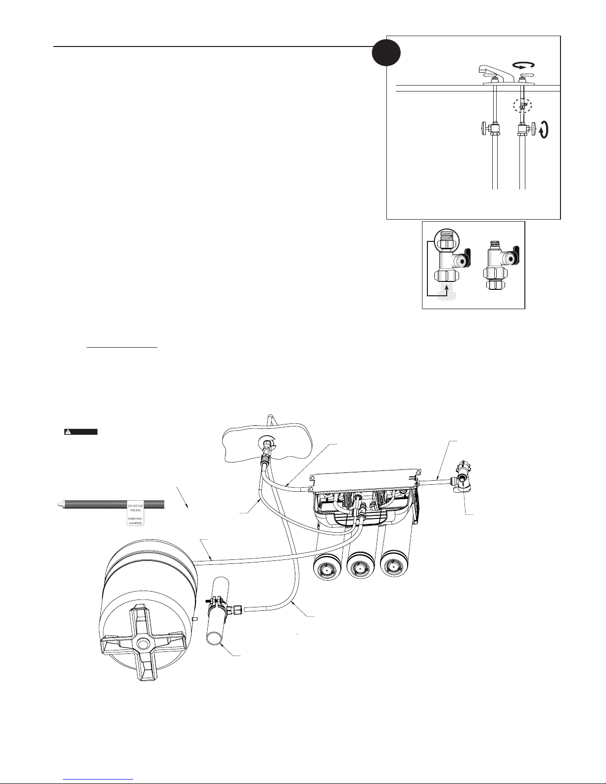
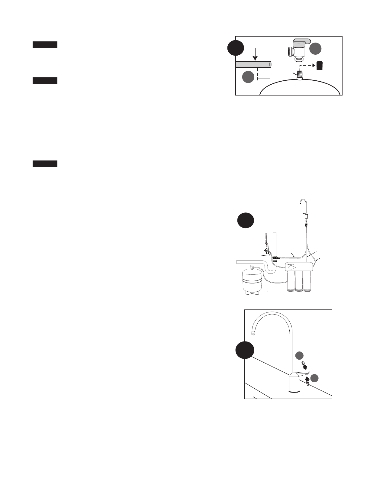
1. Installing the Water Supply Adapter
The supply adapter fits 1/2"-14 NPS supply threads or
3/8" x 3/8" compression. If local codes permit, it may be used to connect the
system to the cold water supply line. If local codes do not permit the use of the
supply adapter, alternate connectors can be obtained from your local supplier.
Directions:
(A) Turn off cold water supply line. If cold water line does not have a shut-off
valve under the sink, you should install one.
(B) Turn on the cold water faucet and allow all water to drain from line.
(C) Disconnect riser cold water supply valve.
(D) Ensure the sealing gasket is fully seated into the feed adapter valve female
thread.
(E) Install feed adapter valve onto supply valve as desired. The feed adapter valve
may be installed at the bottom of the supply hose or the top of the cold water
line. Hand tighten only.
(F) Connect the riser to the feed adapter valve.
NOTE: Be careful not to cross-thread.
The 1/4" red drain tubing includes a
WARNING:
ow controller installed in one end of
the tubing. The end of the tubing
with the ow restrictor must be
installed into the RO system before
attaching to the faucet.
DO NOT cut o the ow restrictor.
RO DRAIN LINE (1/4" RED)
RO LINE TO TANK (3/8” BLUE)
DRAIN PIPE
RO OUTLET LINE (3/8” BLUE)
FAUCET DRAIN LINE (3/8" RED)
RO INLET LINE (3/8” WHITE)
CONNECT TO WATER SUPPLY LINE
FRESHPOINT GRO-350B/GRO-350M Installation and Operation Manual • 5
Page 6
INSTALLATION CONTINUED . . .
CAUTION
CAUTION
CAUTION
CAUTION
CAUTION
WARNING:
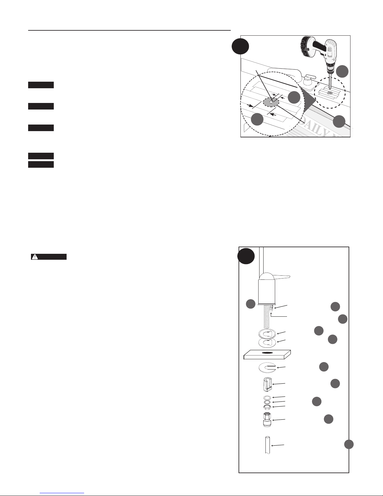
2. Selecting the Faucet Location
The drinking water faucet should be positioned with function, convenience, and
appearance in mind. An adequate flat area is required to allow faucet base to rest
securely. The faucet fits through a 3/4" hole. Most sinks have pre-drilled 1-3⁄8" or
1-1⁄2" diameter holes that may be used for faucet installation. If these pre-drilled
holes cannot be used or are in an inconvenient location, it will be necessary to
drill a 3/4" hole in the sink to accommodate the faucet.
This procedure may generate dusts which can cause severe irritation if
inhaled or come in contact with the eyes. The use of safety glasses and
safety mask for this procedure is recommended.
DO NOT ATTEMPT TO DRILL THROUGH AN ALL-PORCELAIN SINK. If
you have an all-porcelain sink, mount the faucet in pre-drilled sprayer
hole or drill through countertop next to sink.
When drilling through a countertop, make sure the area below the
drilled area is free of wiring and piping. Make certain that you have
ample room to make the proper connections to the bottom of the
faucet.
Do not drill through a countertop that is more than 1" thick.
Do not attempt to drill through a tiled, marble, granite or similar
countertop. Consult a plumber or the countertop manufacturer for
advice or assistance.
The following instructions apply to stainless steel sinks ONLY.
(A) Line bottom of sink with newspaper to prevent shavings, parts or tools from
falling down the drain.
(B) Place masking tape over the area to be drilled to help prevent scratches if
drill bit slips.
(C) Mark point with center punch. Use a 1/4" drill bit to drill a pilot hole through
sink.
1
(D) Use a 1-
⁄4" hole saw to enlarge hole. Smooth rough edges with a file.
3. Mounting the Faucet
Due to variance in installation sites, it is highly recommended to
install the 1/4" red drain tubing to the RO system manifold before
fully mounting the faucet. Make note of the 1/4" red drain tubing
length required to reach from the RO system manifold to the
faucet connection and plan accordingly in relation to mounting
location of system components. Furthermore, the 1/4" red drain
tubing includes a flow controller installed in one end of the
tubing. The end of the tubing with the flow restrictor must be
securely installed into the RO system manifold before attaching to
the faucet. DO NOT cut off the flow restrictor.
NOTE: Not all parts provided with the faucet may be needed for installation.
(A) Slide chrome plate and black rubber washer onto faucet by threading both
drain tubes through the holes on the plate and washer.
(B) Attach large diameter red 3/8" drain tube to barb fitting at the faucet base.
This tube should be long enough to reach the drain clamp in Step 4.
(C) Locate the small diameter red 1/4" drain tube connected to the drain port
of the GRO element. Route the tubing to the faucet and cut off the excessive
length of tubing.
(D) Slide white extension spacer onto long threaded section of faucet. Open end
of extension should come in contact with base of faucet.
(E) Screw washer, lockwasher, and locking nut onto end of faucet threads
(F) Screw quick connector onto end of facuet threads.
(G) Wet end of 3/8" blue tube. Push into bottom of quick connector. Tug gently to
be sure connection is complete.
NOTE: To remove the tube, push on the fittings' collar and pull the tube out.
(H) Holding the faucet, feed the three tubes through the hole in the sink. Position
the faucet handle at a desired location
(I) Center the faucet and slip slotted disc between the white extension spacer
and the bottom of the counter or sink. Tighten the locking nut with a wrench
until it is tight.
2
Pilot Hole
D
3
B
C
1/4"
1
4”
⁄
C
1
⁄4"
1
11⁄4”
D
Mounting
Hole
H
BARB FITTING
(1/4” RED RO DRAIN LINE)
BARB FITTING
(3/8” RED FAUCET DRAIN LINE)
CHROME PLATE
BLACK RUBBER WASHER
COUNTER TOP
SLIP SLOTTED DISC
WHITE EXTENSION SPACER
WASHER
LOCKWASHER
LOCKING NUT
QUICK CONNECTOR
TUBING (3/8” BLUE RO OUTLET LINE)
A
E
A
C
B
A
I
D
F
G
6 • FRESHPOINT GRO-350B/GRO-350M Installation and Operation Manual
Page 7
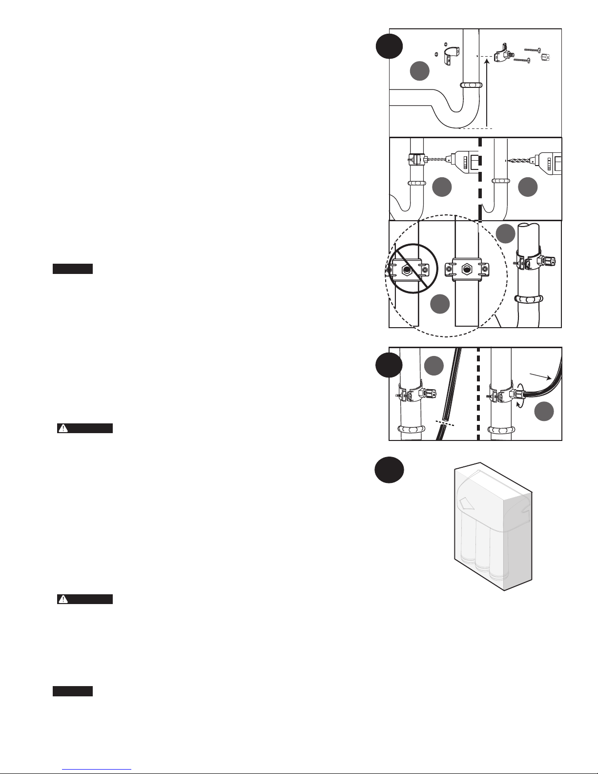
4. Installing the Drain Clamp
CAUTION
WARNING:
WARNING:
CAUTION
5
6
NOTE: If you have a single-basin sink with a disposal unit, call Technical Support
for options.
NOTE: Before installing the drain clamp, check the drainpipes under the sink
for corrosion. Corroded pipes should be replaced before continuing with
installation.
(A) Attach the drain clamp to a vertical section of the drainpipe, about 6" above
the trap. Make sure the opening on the drain clamp is facing towards the
drinking water faucet.
(B) Using the fitting hole of the drain clamp as a guide, drill a 1/4" hole through
one side of the drainpipe.
(C) Remove the drain clamp from the drainpipe and enlarge the hole with a
3/8" drill bit. Use a file to remove rough edges from the drilled hole.
(D) Make sure the black rubber gasket is adhered to the inside of the drain clamp
and place the drain clamp assembly over the drilled hole. Look through the
hole and position the clamp so that the center of the clamp hole is slightly
higher (about 1/16") than the center of the drilled hole. Tighten the clamp
securely.
(E) Screw the plastic compression nut onto the drain clamp until hand-tight.
5. Connecting the Faucet to the Drain
This is a gravity drain line. Any loops, kinks or sharp bends must be
eliminated before proceeding. Failure to create a straight line to the
drain may result in reject water leaking through the air gap in the
faucet onto the countertop and below the faucet.
(A) Align the larger reject 3/8" red tubing from the faucet with the compression
nut on the drain clamp. Create as straight and smooth a path as possible with
the tubing. Do not kink tube. Cut the tubing squarely and remove any internal
and external burrs. Insert inner tube insert (white cone) into end of 3/8" red
tubing. Remove compression nut from the drain clamp. Place compression
nut on end of 3/8" red tubing.
(B) Insert the tubing into the drain port until it stops. Tighten the compression nut
with fingers, then tighten 1 to 2 turns with a wrench to secure tubing to drain
port.
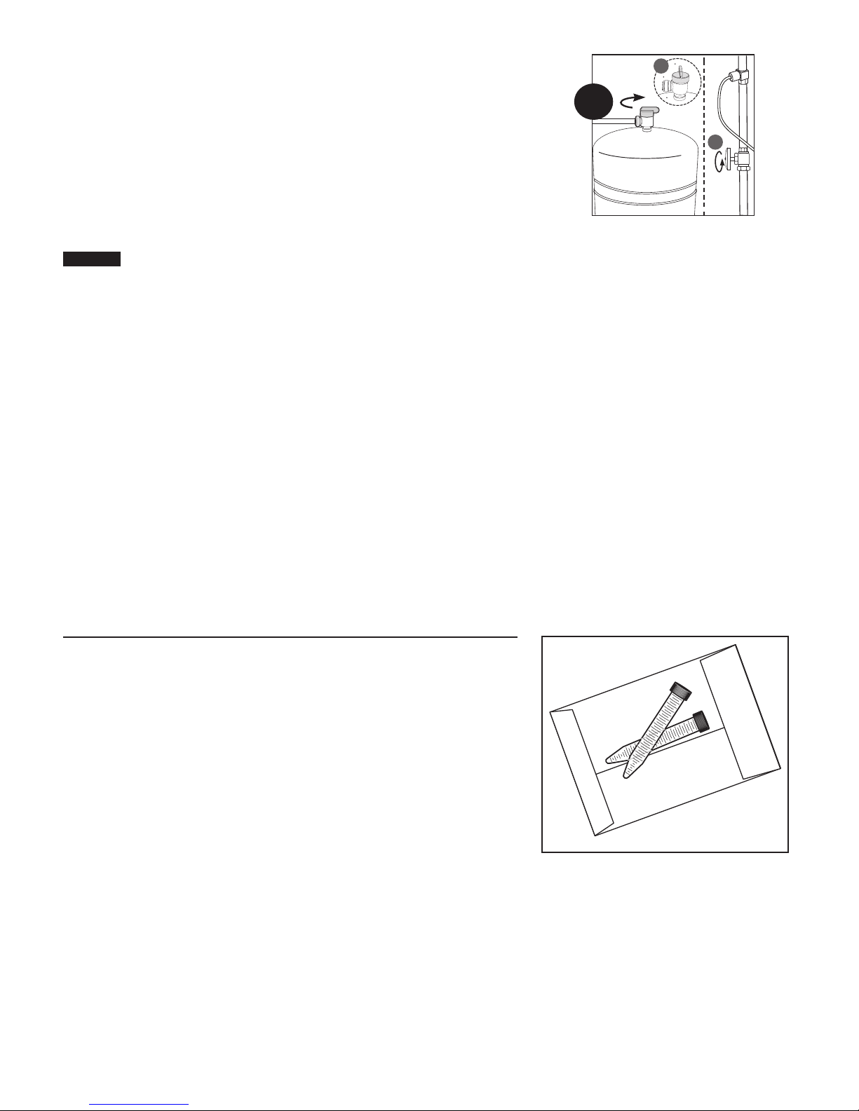
6. Mounting the System
When selecting a mounting location of the system and tank, take
into consideration the length of tubing required for connection
between components. Some installation sites may require more
tubing than provided in the kit.
(A) Select a location under the sink, or other suitable area where the system will
be installed.
NOTE: The system carton can be used to determine the operational footprint
required for installation of the system and replacement cartridges.
(Figure 6)
(B) Mount the system vertically. Ensure mounting is level. Remove filter
cartridges for easier access to bracket mounting holes. Place a pencil mark
in the upper slots of the bracket mounting holes. (Figure 4b). Alternate
mounting option: If mounting the system near the floor, place the pencil
marks above each of the mounting holes on the bracket to ensure enough
space resides below the cartridge and the floor for cartridge replacement
(Figure 4c). Use the 3/32" drill bit to create pilot holes for mounting.
The system should be mounted to a firm, solid surface that is
able to support the weight of the system.
4
6
A
B C
D
A
7” (178 mm)
16.25”
(413 mm)
14”
(356 mm)
6"
E
3/8" Tube
B
7. Connecting the Faucet to the System
(A) Determine the length of plastic blue tubing needed to connect to the outlet
(right) side of the filter from the faucet. Be sure to allow enough tubing to
prevent kinking and cut the tubing squarely. Use a marker to mark one end of
the tubing 5/8" from the end. Wet the end of the 3/8" tube and push into the
outlet (right) connection of the system up to the mark.
Do not bend or crimp tube while inserting.
(B) Gently pull back on the tube to ensure it is connected properly.
FRESHPOINT GRO-350B/GRO-350M Installation and Operation Manual • 7
Page 8

7
RO INLET LINE (3/8” WHITE)
RO DRAIN LINE
RO LINE TO TANK
(3/8” BLUE)
(3/8" RED)
FAUCET DRAIN LINE (1/4” RED)
RO OUTLET LINE (3/8” BLUE)
8 • FRESHPOINT GRO-350B/GRO-350M Installation and Operation Manual
Page 9
INSTALLATION CONTINUED . . .
CAUTION
CAUTION
CAUTION
10
8. Connecting the Storage Tank to the System
When tank is full, it weighs approximately 19.50 lbs. (8.8 kg.) Provide
ample support under the tank.
(A) To prevent leaks, apply 3 or more wraps of plumber tape to threads on tank.
Thread the tank valve onto the top of the tank opening. Turn tank so handle is
in line with tubing.
The tank/valve connection will leak if not properly sealed. Plumber
tape will normally seal the threaded connection.
(B) Locate the 3/8" blue tubing. Place a mark on the tubing 5/8" from one end.
Moisten the marked end of the tubing with water and insert with a twisting
motion into the port of the tank valve until the 5/8" mark is flush with the
quick connect fitting. Then locate the tank near the system's installation
area.
(C) Cut the tubing to correct length. Install free end of tubing into white
quick-connect fitting on the system. Ensure the tubing does not kink. Retain
remaining blue tubing for use in connecting system to water supply adapter.
Some installation sites may require additional tubing not provided in kit.
(D) Place entire system over mounting screws on wall and slide down.
Make certain system is firmly attached to wall to prevent it from falling
and possibly becoming damaged.
NOTE: Use caution not to bend or pinch the tubing behind the system while
attaching to mounting screws.
9. Connecting the System to the Water Supply Adapter
(A) Locate remaining length of 3/8" plastic blue tubing.
(B) Place a mark on the tubing 5/8" from the end. Moisten the end of the tubing
with water and insert with a twisting motion push into white quick connect
fitting on the left side of system. Depending on the installation, the system
may need to be removed from the mounting surface to access the left side of
the system.
(C) Cut the tube to a length that will allow connection to the Water Supply
Adapter. Ensure the tubing does not kink. Place a mark on the tubing
5/8" from the end. Moisten the end of the tubing with water and insert with a
twisting motion push into quick connect fitting on the Water Supply Adapter.
8
RO INLET LINE (3/8” WHITE)
3/8" Tube
B
9
5/8"
Apply
plumber
tape
RO DRAIN LINE
(3/8" RED)
A
FAUCET DRAIN LINE (1/4” RED)
RO OUTLET LINE (3/8” BLUE)
10. Faucet Operation
(A) For controlled water flow, push the handle down.
(B) For constant water flow, lift the faucet handle to lock it in the open position.
RO LINE TO TANK
(3/8” BLUE)
A
Push Down
B
Push Up
FRESHPOINT GRO-350B/GRO-350M Installation and Operation Manual • 9
Page 10
11. System Start-up
CAUTION
NOTE: The reverse osmosis membrane is treated with a food grade sanitizing
agent that may cause an undesirable taste. Although it is not harmful, it
should be flushed from the system.
NOTE: The post-polishing filter may contain fine black carbon particles. These
fines are harmless, but may make the water appear gray in color. The
carbon fines are flushed from the system with the first tank full of water.
NOTE: The RO system does not produce a high volume of water on demand as an
ordinary filter does. Water is produced at a slow, drop-by-drop rate. The
system requires about 2 to 4 hours to fill the storage tank. As water is
taken from the tank, the system automatically starts the cycle of replacing
the water and then stops water production when the tank is full.
Visually check the entire system for leaks.
Troubleshooting on page 14.
(A) Turn off valve at top of storage tank.
(B) Turn on the cold water supply slightly, and ensure the supply adapter valve is
open.
(C) Lift the faucet handle to lock it in the open position and let it drip for 30 min.
(D) Completely open the cold water supply until it comes to a stop. Allow water
to drip from the faucet for 12 more hours. Then close the faucet and open the
valve on the storage tank. The tank valve is open when the handle lines up
with the tubing connection.
(E) Allow 3 hours for the tank to fill. Continue to periodically check the
installation for leaks. After the storage tank is filled, open the faucet to flush
the post-filter cartridge. Allow 4 to 5 minutes for all of the water to drain from
the tank. Close faucet and allow tank to fill.
(F) Repeat step E four times.
NOTE: Initially, the water may appear cloudy. This is a result of air trapped in
the post-polishing filter. It is not harmful and will disappear in a matter
of minutes. It may take up to a week after installing a new post-polishing
filter for the trapped air to dissipate.
The system is ready for operation. You can now enjoy quality water from your
Reverse Osmosis System.
If a leak is present, see
11
Closed Tank Valve
A
Open
Tank Valve
B
Counterclockwise
TESTING YOUR REVERSE OSMOSIS SYSTEM
(NON-MONITORED SYSTEMS ONLY)
Model GRO-350B Reverse Osmosis System
Total Dissolved Solids (TDS) Test
NOTE: It is highly recommended that you (the consumer) have your water
tested at least every 6 months to verify that your system is performing
satisfactorily.
SAMPLING INSTRUCTIONS:
Sampling instructions are included with the Total Dissolved Solids (TDS) Test Kit.
Total Dissolved
Solids Test Kit
10 • FRESHPOINT GRO-350B/GRO-350M Installation and Operation Manual
Page 11
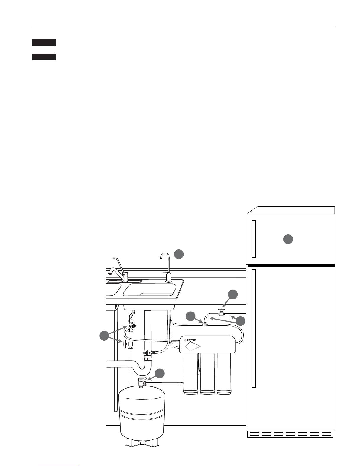
OPTIONAL INSTALLATION
CAUTION
CAUTION
Connecting your Reverse Osmosis System to Refrigerator Icemaker / Water Dispenser
If you are connecting this unit to your refrigerator/icemaker with initial RO installation, wait to turn on the icemaker
until the post-polishing filter has been flushed according to Step 11.
Use plastic tubing and fittings. Do not use copper tubing or brass fittings.
For optimum performance, it is recommended that the distance between the RO system and the refrigerator icemaker/water
NOTE:
dispenser be no greater than 10 feet (3 m). At distances greater than 10 feet, the water pressure from the system may not be
adequate to deliver water to the refrigerator.
MATERIALS REQUIRED(available from your local hardware store):
• 3/8" x 3/8" x 3/8" (0.952 mm x 0.952 mm x 0.952 mm) compression or quick-connect tee
• 10 feet (3 m) of 3/8" (0.952 mm) polyethylene tubing
• Shut-off valve
1. Turn off refrigerator water supply and icemaker (consult manufacturer’s guidelines).
2. Close tank valve (on top of storage tank).
3. Turn off water to RO system at the cold water supply, or at the feed water supply adapter.
4. Open drinking water faucet to relieve pressure.
5.
Locate tubing (permeate) leading to your drinking water faucet. Cut and insert the
3/8"
x
3/8"
x
3/8"
compression or quick-connect tee into the permeate tubing.
Consult manufacturer’s guidelines before installing the supply adapter.
NOTE: When cutting the permeate tubing, you may experience some water leakage.
6. Using a length of 3/8" polyethylene tubing, connect the
icemaker/dispenser line with the free port on the compression tee.
7. The shut-off valve should be installed as close to this port of the tee
as possible. Shut-off valve should be installed in the OFF position
Consult manufacturer’s guidelines before installing the shut-off valve.
8. Completely open cold water supply.
9. Open tank valve.
10. Turn off the drinking water faucet.
11. Turn on water to RO system at cold water supply.
12. Turn on icemaker and open shut-off valve.
Consult manufacturer’s instructions.
13. Check for leaks and tighten connections if necessary.
4
1
3
7
5
6
2
FRESHPOINT GRO-350B/GRO-350M Installation and Operation Manual • 11
Page 12
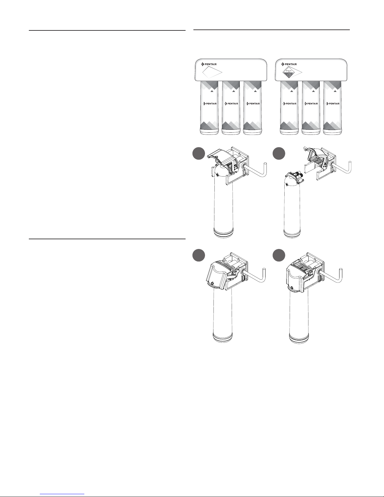
Filter Cartridge Replacement
NOTE: The life of the filter cartridges depends on water
volume used and the quality of the feed water. It is
recommended that the filter cartridges be replaced
every 6-12 months, or when there is a noticeable
change in taste, odor, or flow of filtered water.
Ensure the correct cartridge is purchased for the
system.
Model GRO-350B/GRO-350M uses FDF1-RC, GRO50-RC, and
F1GC-RC Replacement Cartridges
1. Cartridge Replacement
A. Relieve pressure by turning off the water supply to the
system and opening a faucet until water flow stops (wait 5
to 10 minutes after water stops to relieve pressure in RO
membrane). Place a bucket or towel under the system to
catch any water drips.
B. Lift the locking bar upward until the filter cartridge
disengages from the filter head assembly (Figure A).
C. Pull the cartridge away from the filter head assembly and
ensure the locking bar remains in the fully up position
(Figure B).
D. Align the posts on the filter cartridge with the ports in the
filter head assembly. Slide the cartridge filter into the filter
head assembly (engaging with the locking bar causing it to
drop forward and down). (Figure C).
E. Pull down the locking bar until it snaps into place
(Figure D).
Cartridge Sequence
GRO-350B GRO-350M
FDF1-RCFDF1-RC GRO50-RC
A
F1GC-RC
FDF1-RCFDF1-RC GRO50-RC
B
F1GC-RC
Troubleshooting
Leaks between filter head assembly and filter
cartridge
1. Relieve pressure by turning off the water supply to the
system and opening faucet until water flow stops. Place a
bucket or towel under the system to catch any water drips.
2. Remove cartridge and inspect O-rings to make sure they
are seated and clean.
3. Install filter cartridge. Place system into operation and
check for leaks. If leaks persist, turn off the water supply
and contact Technical Support at 1-800-279-9404.
Leaks from tubing fittings
1. Relieve pressure by turning off the water supply to the
system and opening faucet until water flow stops. Place a
bucket or towel under the system to catch any water drips.
2. Depress collet on system or inlet supply adapter tubing
fittings and pull tubing from fitting. Inspect surface of
tubing for scratches or debris. Clean or cut back tubing to
access clean surface.
3. Wet the end of the inlet tubing and press into the inlet
fitting of the system. Ensure the tubing is fully pushed past
the fitting O-rings. Place system into operation and check
for leaks. If leaks persist, turn off the water supply and
contact Technical Support at 1-800-279-9404.
C
D
12 • FRESHPOINT GRO-350B/GRO-350M Installation and Operation Manual
Page 13

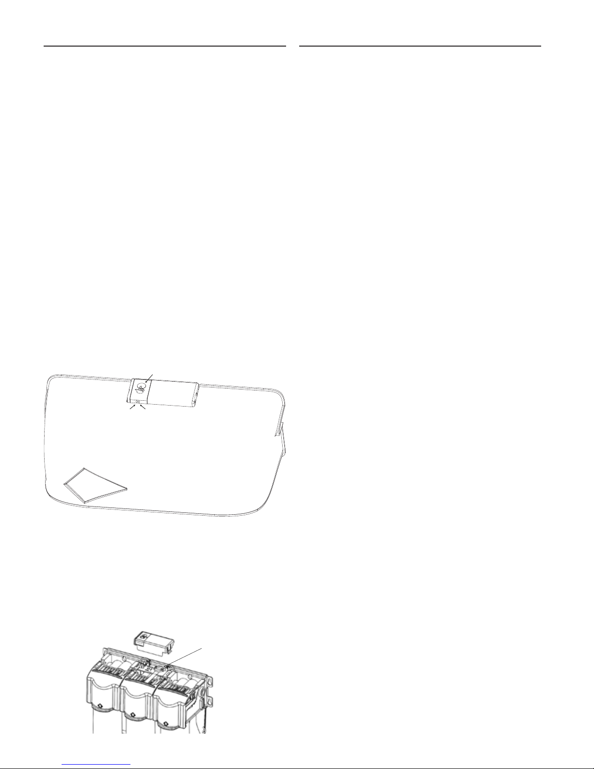
Cartridge Timer Procedure
Metal
Blinks red 1x after 11 months
Blinks red 3x after 12 months
FILTER CARTRIDGE TIMER
(MONITORED SYSTEMS ONLY)
The filter cartridge timer can be installed to the systems
decorative cover by peeling away the adhesive backing on the
metal plate included with the cartridge timer. The timer can
also be attached to a metal magnetic surface using the magnet
that is factory installed on cartridge timer.
INSTALLATION AND ACTIVATION
Once the installation location has been selected, activate the
timer by pulling the plastic tab out from the side of the timer.
Press and release the key to verify the battery is operational.
The light will blink green three times. (Figure A)
NOTE: The timer operates on 12 month schedule. The timer
uses a coin cell type 2023 battery.
The Filter Cartridge Timer is Operational
Operation
1. The timer will begin to blink red once every three minutes
after 11 months, and will blink red three times every three
minutes after 12 months. (Figure B)
NOTE: Timer status of the cartridge life can also be
viewed immediately by pressing and releasing the
key.
Reset Timer
1. To reset the timer after filter cartridge replacement, press
the key and hold for 5 seconds. The timer is now reset to 12
months. (Figure C)
Battery Replacement
1. Replace the battery every 12 months. To replace the battery,
locate the slot on the side of the timer body and carefully
remove the front of the timer. The battery is now accessible.
(Figure D)
2. Slide the new battery under the battery retention bracket
with the positive + side of the battery facing up towards the
battery retention bracket. Align the tab on the timer back
to the slot on the timer front and press and snap both timer
halves together. Battery replacement will not reset the 12
month timer. If reset is required, press and hold key for 5
seconds.
Magnet
A
Blinks
Greeen 3x
Key
B
C
Press and hold for 5 seconds
D
FRESHPOINT GRO-350B/GRO-350M Installation and Operation Manual • 13
Page 14
(MONITORED SYSTEMS ONLY)
The GRO-350M is equipped with a TDS monitor that checks the
Total Dissolved Solids (TDS) the system is reducing from the
water. The TDS Monitor allows the user to test the quality of
the water produced by the system. Test the unit if a noticeable
change occurs in the taste of the drinking water.
The TDS Monitor will display the following colors when
pressing the test button:
Red Light (Left): Water Quality Test Required, proceed to
following steps
1. Draw 1 gallon of water from the unit to purge standing
water from the TDS monitor probes.
2. Push button to test again. If the light is still red, open the
faucet and allow water to run until the storage tank is
empty. Flow from faucet will noticeably decrease indicating
the storage tank is empty.
3. Close faucet and allow system to fill storage tank, 2-3
hours
4. Push button to test. If the light is still red, replace the
membrane cartridge.
Green Light (Right): System Operational
Red and Green Light: Verify inlet and outlet conductivity probes
dry, no water to system
No Lights: The battery needs to be changed. Replace battery
every 12 months.
NOTE: The TDS monitor is activated during initial installation
by pulling the plastic tab out from the TDS monitor.
TDS MONITOR TEST BUTTON
RED LED
GREEN LED
TROUBLESHOOTING GUIDETDS MONITOR
Leaks on tank valve assembly
1. Open drinking water faucet to drain storage tank. Let
drinking water faucet run until it drips. Turn off cold water
supply.
2. Push in on white collar of tank valve fitting and pull out
tubing. Unscrew the tank valve from the storage tank.
Rewrap threads on top of the tank with plumber tape. Screw
tank valve back onto tank. Trim 1/2" from end of tubing and
reinsert 5/8" into tank valve fitting.
3. Open the cold water supply and shut off the reverse osmosis
faucet. Let the system pressurize for several hours and
check for leaks. Check again after tank is fully pressurized.
Leaks on quick-connect fittings
1. Close the cold water supply and tank valve.
2. Depress plastic collar and pull out tubing.
3. Cut off 1" of tubing and place a mark 5/8" from end of
tubing. Tubing should be cut squarely. The internal and
external burrs should be removed.
4. Push tubing 5/8" into fitting.
5. Open the cold water supply and tank valve. If leaks persist,
call Technical Support.
High TDS in Product Water
If high levels of TDS (Total Dissolved Solids) are detected in
your product water as determined by the TDS Monitor or by the
TDS test kit, the cartridge membrane may need to be replaced
or the reject flow control may be clogged. See your dealer or
plumber to check product water TDS.
Reduced production
Slow or no product water flow usually indicates a clogged
cartridge.
Gradual return of taste and odor
Gradual return of unpleasant taste and odor over a period of
time may indicate that your cartridges need to be replaced.
Sudden return of taste and odor
If shortly after complete servicing noticeable taste and odors
return, contact Technical Support.
No water pressure from the drinking water faucet
or low volume in storage tank
1. Close the cold water supply to system.
Replacing the Battery
1. Replace the battery every 12 months. To replace the
battery, remove the TDS Monitor Cover and remove the
battery from retainer.
2. Slide the new battery under the battery retention bracket
with the positive + side of the battery facing up towards the
battery retention bracket.
3. Install TDS Cover and press button to verify operation.
BATTERY
REPLACEMENT
14 • FRESHPOINT GRO-350B/GRO-350M Installation and Operation Manual
2. Lift storage tank to see if it is empty. If not, open the
drinking water faucet to empty water from tank.
NOTE: It may be necessary to pump a small amount of air into
the tank with a bicycle pump to remove all the water
from the tank.
3. When tank is empty, use a pressure gauge to check
tank pressure. An empty tank should contain 5 to 7 psi
pressure. Increase or decrease the air pressure in the tank
accordingly.
4. Open cold water supply. Let system run for 3 hours to fill
tank, then check system performance. If performance has
not improved, call Technical Support.
Page 15

GRO350B PARTS GUIDE
1
2
4
1/4" NPT
6
5
7
8
3
9
ITEM NO. PART NO. DESCRIPTION QTY
1 4005008 ASSY, RO 3-STAGE 1
2 4004917 ASSY, 3 STAGE COVER, MAGNET 1
3 4003597 KIT, RO SYSTEMS 50 GPD 1
4 244820 FAUCET AIR-GAP 1
5 244833 TANK, RO 1/4" NPT 1
6 655123-96 FDF1-RC Cartridge Filter 1
7 655121-96 GRO50-RC Cartridge Membrane 1
8 655117-96 F1GC-RC Cartridge Filter 1
9 4003280 SHROUD, ASO 1
For replacement parts, contact your nearest Water Filter dealer or call 800.279.9404
FRESHPOINT GRO-350B/GRO-350M Installation and Operation Manual • 15
Page 16

GRO350M PARTS GUIDE
1
2
4
1/4" NPT
6
5
7
8
3
9
10
ITEM NO. PART NO. DESCRIPTION QTY
1 4005011 RO HEAD, MODEL GRO-350M 1
2 4004919 ASSY, 3 STAGE COVER, MAGNET 1
3 4003597 KIT, RO SYSTEMS 50 GPD 1
4 244820 FAUCET AIR-GAP 1
5 244833 TANK, RO (STL 3.2 GAL) 1/4" NPT 1
6 655123-96 FDF1-RC CARTRIDGE FILTER 1
7 655121-96 GRO50-RC CARTRIDGE MEMBRANE 1
8 655117-96 F1GC-RC CARTRIDGE FILTER 1
9 4003280 SHROUD, ASO 1
10 4003641 TIMER, FILTER CARTRIDGE 1
16 • FRESHPOINT GRO-350B/GRO-350M Installation and Operation Manual
Page 17

WARNING:
PERFORMANCE DATA
IMPORTANT:
Read this performance data and compare the capabilities of
this system with your actual water treatment needs.
It is recommended that before installing a water treatment
system, you have your water supply tested to determine your
actual water treatment needs.
This system has been tested according to NSF/ANSI 58 for the
reduction of substances listed below. The concentration of the
indicated substances in water enteringthe sysem was reduced
to a concentration less than or equal to the permissible limit
for water leaving the system as specified in NSF/ANSI 58.
The GRO-350B/GRO-350M shall only be used for arsenic
reduction on chlorinated water supplies containing detectable
residual free chlorine at the system inlet. Water systems using
an in-line chlorinator should provide a one-minute chlorine
contact time before the RO system.
Do not use with water that is microbiologically
unsafe or of unknown quality without adequate disinfection
before or after the system. Systems certified for cyst reduction
may be used on disinfected waters that may contain filterable
cysts.
NOTE: Substances reduced are not necessarily in your water.
Filter must be maintained according to manufacturer’s
instructions, including replacement of filter cartridges.
The tested efficiency rating for these systems is 22.05%.
Efficiency rating means the percentage of the influent water
to the system that is available to the user as reverse osmosis
treated water under operating conditions that approximate
typical daily usage.
The tested recovery rating is 38.65%. Recovery rating means
the percentage of the influent water to the membrane portion
of the system that is available to the user as reverse osmosis
treated water when the system is operated without a storage
tank or when the storage tank is bypassed.
The GRO-350B/GRO-350M has been tested for the treatment
of water containing pentavalent arsenic [also known as As(V),
As(+5), or arsenate] at concentrations of 0.050 mg/L or less.
This system reduces pentavalent arsenic, but may not remove
other forms of arsenic. This system is to be used on water
supplies containing a detectable free chlorine residual or on
water supplies that have been demonstrated to contain only
pentavalent arsenic. Treatment with chloramine (combined
chlorine) is not sufficient to ensure complete conversion
of trivalent arsenic to pentavalent arsenic. Please see the
Arsenic Facts section of the Performance Data Sheet for
further information.
EPA # 082989-CHN-001
System Production Rate: 14.96 gpd (56.63 Lpd)
Recovery Rating: 38.65%
Efficiency Rating: 22.05%
TDS Rejection: 96.9%
C US
System Tested and Certified by NSF International
against NSF/ANSI Standard 42, 58, and CSA B483.1
for the reduction of the claims specified on the
Performance Data Sheet.
GRO-350B/GRO-350M SYSTEM INSTALLED
WITH FDF1-RC, GRO50-RC, F1GC-RC
FILTER CARTRIDGES
Model GRO-350B / GRO-350M
Substance
Standard 42
Chlorine
Taste and Order
Standard 58
Total Dissolved Solids 750 ± 40 mg/L 187 mg/L 96.9%
Pentavalent Arsenic 0.050 mg/L ± 10% 0.010 mg/L 88.0%
Fluoride 8.0 mg/L ± 10% 1.5 mg/L 93.6%
Cysts* Minimum 50,000/mL 99.95% >99.99%
Turbidity 11 mg/L ± 1 NTU 0.5 NTU >99.1%
Lead 0.15 mg/L ± 10% 0.010 mg/L 98.6%
Selenium 0.10 mg/L ± 10% 0.05 mg/L 97.9%
Copper 3.0 mg/L ± 10% 1.3 mg/L 98.5%
Cadmium 0.03 mg/L ± 10% 0.005 mg/L 99.1%
Hexavalant Chromium 0.3 mg/L ± 10% 0.1 mg/L 96.4%
Trivalent Chromium 0.3 mg/L ± 10% 0.1 mg/L 98.2%
Radium 226/228 25 pCi/L ± 10% 5 pCi/L 80.0%
Barium 10.0 mg/L ± 10% 2.0 mg/L 96.3%
*NSF/ANSI Standard 58 certified to reduce cysts such as Cryptosporidium and Giardia by mechanical
means.
Influent Challenge
Concentration
2.0 mg/L ± 10% ≥50% 95.9%
Arsenic Fact Sheet
Arsenic (abbreviated As) is found naturally in some well
water. Arsenic in water has no color, taste or odor. It must
be measured by a lab test. Public water utilities must have
their water tested for arsenic. You can get the results from
your water utility. If you have your own well, you can have
the water tested. The local health department or state
environmental health agency can provide a list of certified
labs. There are two forms of arsenic: pentavalent arsenic [also
called As(V), As(+5), and arsenate] and trivalent arsenic [also
called As(III), As(+3) and arsenite]. In well water, arsenic may
be pentavalent, trivalent, or a combination of both. Special
sampling procedures are needed for a lab to determine what
type and how much of each type of arsenic is in the water.
Check with the labs in your area to see if they can provide
this type of service. Reverse osmosis (RO) water treatment
systems do not remove trivalent arsenic from water very well.
RO systems are very effective at removing pentavalent arsenic.
A free chlorine residual will rapidly convert trivalent arsenic to
pentavalent arsenic. Other water treatment chemicals such as
ozone and potassium permanganate will also change trivalent
arsenic to pentavalent arsenic. A combined chlorine residual
(also called chloramine) may not convert all the trivalent
arsenic. If you get your water from a public water utility,
contact the utility to find out if free chlorine or combined
chlorine is used in the water system. The GRO-350B/GRO350M system is designed to remove pentavalent arsenic.
It will not convert trivalent arsenic to pentavalent arsenic.
The system was tested in a lab. Under those conditions, the
system reduced 0.050 mg/L (ppm) pentavalent arsenic to
0.010 mg/L (ppm)(the USEPA standard for drinking water)
or less. The performance of the system may be different at
your installation. Have the treated water tested for arsenic to
check if the system is working properly. The RO component
of the GRO-350B/GRO-350M system must be replaced every
12-24 months to ensure the system will continue to remove
pentavalent arsenic. The component identification and
locations where you can purchase the component are listed in
the installation/operation manual.
Max Permissible
Product Water
Concentration
Reduction
Requirements
Average
Reduction
FRESHPOINT GRO-350B/GRO-350M Installation and Operation Manual • 17
Page 18

IMPORTANTE: Antes de instalar este sistema de ósmosis
ADVERTENCIA:
inversa, asegúrese de que el suministro de agua cumpla con las
siguientes especificaciones de funcionamiento. No cumplir con las
especificaciones puede reducir la efectividad del sistema y anulará la
garantía.
ESPECIFICACIONES
Gama de presión: 40 a 100 psi (2.75–6.89 bares)
Gama de Temperatura: 40-100 °F (4.4-37.8 °C)
Sólidos disueltos totales: <2000ppm
†
Dureza máxima
Sulfuro, hierro y manganeso
Cloro en el suministro de agua: <2ppm
Límites de pH: 3-11
Dimensiones totales: 11.32” ancho x 5.46” prof. x 12.54” alto
(288 mm x 139 mm x 319 mm)
Peso: 7.1 lbs (3.2 kg)
Dimensiones del tanque: 8.94” diám x 13.83” alto
(227mm diám x 351 mm alto)
Capacidad máxima del tanque: 2.1 gal (7.9 L)
Presión de aire del tanque
vacío: 5-7 psi (0.34-0.48 bares)
Peso del tanque (lleno): 19.50 lb (8.8 kg)
†
Si la dureza del agua sobrepasa los 10 gpg (171 mg/L), se acumulará
sarro rápidamente en la membrana. La acumulación del sarro tapará
la membrana y hará que el sistema sea ineficaz. No se recomienda
el uso de estos sistemas de ósmosis inversa en aguas con dureza
superior a 10 gpg (171 mg/L).
‡
Se permite un nivel máximo total de aproximadamente 0.01ppm de
sulfuro, hierro o manganeso. Consulte con su representante local para
reducir estas sustancias en el agua.
: <10 gpg (170 mg/L)
‡
: <0.1ppm
Herramientas y materiales requeridos
• Taladro de mano o eléctrico (se prefiere inalámbrico)
• (2) llaves inglesas
• Destornilladores planos y Phillips
• Lima
• Gafas de seguridad
• Brocas: 1/8", 3/16", 1/4", 3/8"
• Cortatubos o navaja multiuso
• Lápiz
• Toalla
• Cubeta
• Puntas de destornillador: 1/8", 3/16", 1/4", 3/8"
Si el fregadero no tiene orificio para una llave separada:
• Punzón
• Broca común o broca hueca cilíndrica de 3/4''
• Máscara de seguridad
NOTA: Es posible que no necesite todas las herramientas para la
instalación. Lea los procedimientos de instalación antes
de comenzar para determinar qué herramientas son
necesarias.
PIEZAS INCLUIDAS:
• Sistema con cartuchos
• Tanque de almacenamiento
• Kit de tornillería de instalación
• Llave de agua potable sin plomo con espacio de aire
ADVERTENCIA RELACIONADA CON LA
PROPUESTA 65 DE CALIFORNIA
18 • FRESHPOINT GRO-350B/GRO-350M Installation and Operation Manual
Este producto contiene productos químicos de los
cuales el estado de California sabe causan cáncer o
anomalías congénitas u otros daños reproductivos.
Page 19

ADVERTENCIA:
PRECAUCIÓN:
PRECAUCIONES
GENERAL
No se debe utilizar con agua microbiológicamente
insegura o de calidad desconocida sin la
desinfección adecuada previa o posterior al paso
por el sistema. Los sistemas certificados para la
reducción de quistes* pueden usarse en aguas
desinfectadas que pudieran contener quistes
filtrables.
*Con certificado de la Norma 58 de NSF/ANSI para reducir los quistes
como Cryptosporidium y Giardia por medios mecánicos
Se debe proteger el sistema de ósmosis inversa contra el
congelamiento para evitar la rotura de los componentes
de ósmosis inversa y fugas de agua.
NOTA:
• El agua debe estar dentro de los limites requeridos para
un funcionamiento satisfactorio. De lo contrario, la vida
de la membrana se acortará y se anulará su garantía (ver
Especificaciones en la página 18).
• Este sistema de ósmosis inversa no protege de bacterias causantes
de enfermedades ni remueve bacterias inofensivas que están
presentes en forma natural.
• Instale solo en la línea de agua fría.
• Asegúrese de que la instalación cumpla con todas las leyes y
normas estatales y locales.
• Los cartuchos de repuesto y el elemento de ósmosis inversa
incluidos en este sistema tienen una vida útil limitada. Los cambios
en el sabor, olor o color del agua filtrada indican que el cartucho de
filtro debe ser reemplazado.
• Luego de períodos prolongados sin uso, como por ejemplo durante
las vacaciones, se recomienda enjuagar el sistema durante
5minutos antes de ser usado.
• Un cartucho para agua potable puede contener finos de carbono
(polvo negro muy fino). Después de la instalación, enjuague el
sistema durante5 minutos para eliminar los finos de carbón antes
de utilizar el agua.
• Se recomienda dejar correr el agua durante al menos 20segundos
antes de utilizar el agua para beber o cocinar.
• Las sustancias contaminantes que este dispositivo de tratamiento
de agua elimina o reduce no están necesariamente presentes en el
agua que usted consume.
CÓMO FUNCIONA LA ÓSMOSIS INVERSA
El sistema de ósmosis inversa (RO) GRO-350B/GRO-350M utiliza una
membrana semipermeable para reducir las sales y los minerales
disueltos, y así mejorar el gusto y olor de su agua. La membrana RO
está hecha con una película micro delgada bobinada alrededor de un
núcleo central hueco. Las moléculas de agua pueden pasar a través
de la membrana, pero se rechazan las sales y minerales disueltos.
El sistema de ósmosis inversa GRO-350B/GRO-350M cuenta con una
acción de filtro de 3etapas. Su suministro de agua se prefiltra para
reducir la suciedad y el cloro que pueden contaminar la membrana.
La membrana de ósmosis inversa separa esta agua prefiltrada en
AGUA DE PRODUCTO y AGUA RECHAZADA o DE DESAGÜE. La presión
del suministro de agua provoca que el agua de producto pase a través
de la membrana y entre al tanque de almacenamiento. Los sólidos
disueltos y otros contaminantes no pueden pasar a través de la
membrana y son enviados al desagüe como agua rechazada. Cuando
abre la llave de agua potable, el agua de producto se extrae del tanque
de almacenamiento a través de un posfiltro de carbón activado,
brindando así agua más limpia y con mejor sabor.
Por cada litro de agua producida, varios litros se desechan como
agua rechazada. El tanque de almacenamiento puede almacenar
hasta 2.1 galones (7.9 litros) por vez, para beber y cocinar. Cuando
se usan según las Especificaciones de la página 18 del manual, las
membranas de ósmosis inversa deberían durar de 12 a 24 meses.
FRESHPOINT GRO-350B/GRO-350M Installation and Operation Manual • 19
Page 20

1
INSTALACIÓN
• Lea todas las instrucciones y precauciones antes de instalar y usar su GRO-350B/
GRO-350M.
• Para una instalación normal bajo el fregadero en tuberías de agua fría de acero, latón
o cobre de 3/8".
• Al seleccionar una ubicación de montaje del sistema y tanque, tenga en cuenta la
longitud de la tubería necesaria para las conexiones entre la plomería existente y
los componentes del sistema. Algunos sitios de instalación podrían necesitar más
tubería que la que se suministra en el kit.
• Los diagramas numerados corresponden a los pasos numerados.
1. Cómo instalar el adaptador de suministro de agua
El adaptador de suministro es para roscas 1/2"-14 NPS
o de compresión de 3/8" x 3/8". Si los códigos locales lo permiten, puede utilizarse para
conectar el sistema a la tubería de agua fría. Si los códigos locales no permiten el uso
del adaptador de suministro, sus proveedores locales pueden facilitarle conectores
alternativos.
Instrucciones:
(A) Cierre la tubería de suministro de agua fría. Si la tubería de agua fría no tiene una
válvula de cierre bajo el fregadero, deberá instalar una.
(B) Abra la llave de agua fría y permita que se desagüe toda el agua de la tubería.
(C) Desconecte la válvula de suministro de agua fría del tubo vertical.
(D) Asegúrese de que la junta selladora esté completamente asentada en la rosca hembra
de la válvula del adaptador de alimentación.
(E) Instale la válvula del adaptador de alimentación sobre la válvula de suministro en la
forma deseada. La válvula del adaptador de alimentación se puede instalar en la parte
inferior de la manguera de suministro o en la parte superior de la tubería de agua fría.
Apriete a mano exclusivamente.
(F) Conecte el tubo vertical a la válvula del adaptador de alimentación.
NOTA: Tenga cuidado de no trasroscar.
ADVERTENCIA:
La tubería de desagüe roja de 1/4"
incluye un controlador de ujo instalado
en un extremo de la tubería. El extremo
de la tubería con el limitador de ujo se
debe instalar en el sistema de ósmosis
inversa antes de unirlo a la llave. NO
corte el limitador de ujo.
NO CORTE
ESTE EXTREMO
LÍNEA DE DESAGÜE DE ÓSMOSIS
INSERTE EN EL
COLECTOR
INVERSA (1/4" ROJA)
LÍNEA DE ÓSMOSIS INVERSA
AL TANQUE (3/8” AZUL)
LÍNEA DE DESAGÜE
LÍNEA DE SALIDA DE ÓSMOSIS
INVERSA (3/8" AZUL)
LÍNEA DE DESAGÜE DE LLAVE (3/8" ROJA)
LÍNEA DE ENTRADA DE
ÓSMOSIS INVERSA
(3/8" BLANCA)
CONECTAR A LA LÍNEA
DE SUMINISTRO DE AGUA
20 • FRESHPOINT GRO-350B/GRO-350M Installation and Operation Manual
Page 21

INSTALACIÓN CONTINUACIÓN . . .
PRECAUCIÓN:
PRECAUCIÓN:
PRECAUCIÓN:
ADVERTENCIA:
2. Selección de la ubicación de la llave de agua
Se debe prever la funcionalidad, la conveniencia y el aspecto de la llave de agua potable antes
de su colocación. Se necesita una superficie plana adecuada de modo que la base de la llave
de agua se asiente firmemente. La llave calza a través de un orificio de 3/4''. La mayoría de
los fregaderos tienen orificios de 1-3⁄8'' o 1-1/2'' de diámetro previamente perforados que
se pueden utilizar para instalar la llave de agua. Si no se pueden usar estos orificios o están
en una ubicación inconveniente, será necesario perforar un orificio de 3/4'' de diámetro en el
fregadero para acomodar la llave de agua.
Este procedimiento puede producir polvos que pueden causar una irritación grave
si se aspiran o entran en contacto con los ojos. Se recomienda llevar anteojos de
seguridad y una máscara de seguridad durante este procedimiento.
PRECAUCIÓN:
PRECAUCIÓN:
Las siguientes instrucciones se aplican ÚNICAMENTE a los fregaderos de acero inoxidable.
(A) Cubra el fondo del fregadero con papel de periódico para impedir que caigan al drenaje
(B) Coloque cinta de enmascarar sobre el área que se va a perforar para ayudar a evitar
(C) Marque el punto con un punzón de marcar. Use una broca de 1/4" para hacer un orificio de
(D) Use un sacabocados de 1
NO TRATE DE PERFORAR UN FREGADERO HECHO TOTALMENTE DE
PORCELANA. Si tiene un fregadero hecho totalmente de porcelana, monte la llave
de agua en el orificio previamente perforado para el rociador o perfore un orificio
en la cubierta adyacente al fregadero.
Cuando perfore a través de la cubierta asegúrese de que no haya cables ni
tuberías debajo del área donde se hará la perforación. Asegúrese de que haya
un amplio espacio para hacer las conexiones adecuadas en la parte inferior de la
llave de agua.
No perfore a través de una cubierta de un espesor mayor a 1".
No trate de perforar a través de una cubierta de azulejo, mármol, granito o
materiales similares. Consulte con un plomero o con el fabricante de la cubierta
para obtener consejos o asistencia.
virutas, piezas o herramientas.
rayones si la broca del taladro se resbala.
guía a través del fregadero.
lima.
1
⁄4" para ensanchar el orificio. Alise los bordes ásperos con una
3. Colocación de la llave de agua
Debido a la variación en los sitios de instalación, se recomienda
especialmente que instale la tubería de desagüe roja de 1/4" en el colector
del sistema de ósmosis inversa antes de montar la llave por completo.
Anote la longitud de tubería de desagüe roja de 1/4" necesaria para llegar
del colector del sistema de ósmosis inversa hasta la conexión de la llave
y planear en consecuencia en relación con la ubicación de montaje de los
componentes del sistema. Además, la tubería de desagüe roja de 1/4"
incluye un controlador de flujo instalado en un extremo de la tubería. El
extremo de la tubería con el limitador de flujo se debe instalar de manera
segura en el colector del sistema de ósmosis inversa antes de unirlo a la
llave. NO corte el limitador de flujo.
NOTA: Es posible que no se necesiten para la instalación todas las piezas proporcionadas con
la llave.
(A) Enrosque ambas tuberías de desagüe a través de los orificios en la placa y la arandela
para deslizar la placa cromada y la arandela de caucho negro sobre la llave.
(B) Una la tubería de desagüe de 3/8" roja de diámetro grande a la conexión de espiga
en la base de la llave. Esta tubería debe ser lo suficientemente larga para alcanzar la
abrazadera de drenaje del Paso 4.
(C) Ubique la tubería de desagüe de 1/4" roja de diámetro pequeño conectada al puerto de
desagüe del elemento GRO. Tienda la tubería hasta la llave y corte el exceso de tubería.
(D) Deslice el espaciador de extensión blanco sobre la sección roscada larga de la llave. El
extremo abierto de la extensión deberá estar en contacto con la base de la llave.
(E) Atornille la arandela, arandela de seguridad y contratuerca en el extremo de las roscas
de la llave.
(F) Atornille el conector rápido en el extremo de las roscas de la llave.
(G) Moje el extremo del tubo azul de 3/8". Empuje a la parte inferior del conector rápido. Jale
suavemente para asegurarse de que la conexión esté completa.
NOTA: Para retirar el tubo, empuje el collarín de la conexión y jale el tubo.
(H) Sosteniendo la llave, pase los tres tubos a través del orificio en el fregadero. Ponga la
empuñadura de la llave en la ubicación deseada.
(I) Centre la llave y deslice el disco ranurado entre el espaciador blanco y el fondo de la
cubierta o el fregadero. Apriete la contratuerca con una llave hasta que quede apretada.
2
Orificio de guía
C
D
1
⁄4"
1
11⁄4”
D
3
H
1/4"
1
4”
⁄
C
Orificio de
CONEXIÓN DE ESPIGA
(LÍNEA DE DESAGÜE DE
ÓSMOSIS INVERSA 1/4”
ROJA)
CONEXIÓN DE ESPIGA
(LÍNEA DE DESAGÜE DE
LLAVE 3/8” ROJA)
PLACA CROMADA
ARANDELA DE GOMA
NEGRA
CUBIERTA
DISCO RANURADO
ESPACIADOR DE
EXTENSIÓN BLANCO
ARANDELA
ARANDELA DE PRESIÓN
CONTRATUERCA
CONECTOR RÁPIDO
TUBERÍA (LÍNEA DE
SALIDA DE ÓSMOSIS
INVERSA 3/8” AZUL)
B
A
montaje
C
B
A
A
I
D
E
F
G
FRESHPOINT GRO-350B/GRO-350M Installation and Operation Manual • 21
Page 22

4. Instalación de la abrazadera de drenaje
PRECAUCIÓN:
ADVERTENCIA:
ADVERTENCIA:
PRECAUCIÓN:
5
6
NOTA: Si tiene un fregadero de una sola tina con un triturador, llame a Asistencia Técnica
para obtener más opciones.
NOTA: Antes de instalar la abrazadera de drenaje, revise si los tubos de desagüe bajo el
fregadero tienen corrosión. Las tuberías con corrosión deben ser reemplazadas
antes de continuar con la instalación.
(A) Coloque la abrazadera de desagüe en una sección vertical de la tubería de desagüe,
alrededor de 6'' sobre el sifón. Asegúrese de que la abertura de la abrazadera de
desagüe esté viendo hacia la llave de agua potable.
(B) Con el orificio del acoplamiento de la abrazadera de desagüe como guía, perfore un
orificio de 1/4'' a un lado de la tubería de desagüe.
(C) Quite la abrazadera de desagüe de la tubería de desagüe y ensanche el orificio con una
broca de 3/8''. Utilice una lima para quitar los bordes ásperos del orificio perforado.
(D) Asegúrese de que la junta de goma negra esté adherida al interior de la abrazadera de
desagüe y coloque el conjunto de la abrazadera de desagüe sobre el orificio perforado.
Mire a través del orificio y posicione la abrazadera para que el centro del orificio de
la abrazadera sea apenas más alto (alrededor de 1/16'') que el centro del orificio
perforado. Apriete la abrazadera firmemente.
(E) Atornille la tuerca de compresión plástica a la abrazadera de desagüe hasta que no
pueda apretar más con la mano.
5. Conexión de la llave de agua al desagüe
Este es un desagüe de gravedad. Cualquier bucle, doblez o curvas peligrosas
se debe eliminar antes de continuar. No crear una línea recta al desagüe puede
provocar que el agua rechazada se fugue a través del espacio de aire en la llave
de agua hacia la cubierta y debajo de la llave de agua.
(A) Alinee la tubería más grande de rechazo roja de 3/8'' de la llave de agua con la tuerca
de compresión en la abrazadera de desagüe. Cree un pasaje lo más recto y liso posible
con la tubería. No retuerza la tubería. Corte la tubería en ángulo recto y retire las
rebabas internas y externas. Inserte el inserto del tubo interior (cono blanco) en el
extremo de la tubería roja de 3/8". Retire la tuerca de compresión de la abrazadera de
desagüe. Ponga la tuerca de compresión en el extremo de la tubería roja de 3/8".
(B) Inserte la tubería dentro del puerto de desagüe hasta que se detenga. Apriete la tuerca
de compresión con los dedos, luego apriete 1 a 2 vueltas con una llave para asegurar la
tubería al puerto de desagüe.
4
A
B C
D
A
6"
E
Tubo de
3/8''
6. Cómo montar el sistema
Al seleccionar una ubicación de montaje del sistema y tanque, tenga
en cuenta la longitud de la tubería necesaria para la conexión entre los
componentes. Algunos sitios de instalación podrían necesitar más tubería
que la que se suministra en el kit.
(A) Seleccione una ubicación bajo el fregadero, u otra área adecuada en la que se instalará
el sistema.
NOTA: Se puede usar el cartón del sistema para determinar la huella de operación que se
requiere para la instalación del sistema y los cartuchos de repuesto. (Figura 6)
(B) Monte el sistema verticalmente. Asegúrese de que la montura esté al ras. Retire los
cartuchos de filtro para facilitar el acceso a los orificios del soporte de montaje. Ponga
una marca con lápiz en las ranuras superiores de los orificios de los soportes de
montaje (Figura 4b). Opción de montaje alternativa: Si está montando el sistema cerca
del piso, ponga las marcas con lápiz encima de cada uno de los orificios de montaje en
el soporte para asegurar que haya suficiente espacio debajo del cartucho y el piso para
el reemplazo del cartucho (Figura 4c). Use la broca de 3/32'' para crear orificios de
guía para el montaje.
El sistema se deberá montar en una superficie sólida y firme que pueda
apoyar el peso del sistema.
7. Conexión de la llave de agua al sistema
(A) Determine la longitud de la tubería azul de plástico que se necesita para conectar al
lado de la salida (derecho) del filtro desde la llave. Asegúrese de dejar suficiente
tubería pare evitar retorcimientos y corte el tubo en ángulo recto. Use un marcador
para marcar un extremo de la tubería a 5/8" del extremo. Moje el extremo del tubo de
3/8" y empújelo a la conexión de salida (derecha) del sistema hasta la marca.
No doble ni engarce el tubo que está insertando.
(B) Jale levemente del tubo para corroborar que esté correctamente conectado.
B
7” (178 mm)
6
16.25”
(413 mm)
14”
(356 mm)
22 • FRESHPOINT GRO-350B/GRO-350M Installation and Operation Manual
Page 23

7
LÍNEA DE ENTRADA DE
ÓSMOSIS INVERSA
(3/8" BLANCA)
LÍNEA DE DESAGÜE DE
ÓSMOSIS INVERSA
(3/8" ROJA)
LÍNEA DE ÓSMOSIS
INVERSA AL TANQUE
(3/8” AZUL)
LÍNEA DE DESAGÜE DE LLAVE
(1/4" ROJA)
LÍNEA DE SALIDA DE
ÓSMOSIS INVERSA
(3/8" AZUL)
FRESHPOINT GRO-350B/GRO-350M Installation and Operation Manual • 23
Page 24

INSTALACIÓN CONTINUACIÓN . . .
PRECAUCIÓN:
10
8. Conexión del tanque de almacenamiento al sistema
Cuando el tanque está lleno, pesa aproximadamente 19.50 libras (8.8 kg.).
Coloque un soporte amplio debajo del tanque.
(A) Para prevenir las fugas, aplique 3 vueltas o más de cinta de teflón a las roscas del
tanque. Enrosque la válvula del tanque sobre la parte superior de la abertura del
tanque. Gire el tanque de modo que la manivela quede alineada con la tubería.
PRECAUCIÓN:
(B) Ubique la tubería azul de 3/8". Haga una marca en el tubo de 5/8'' desde un extremo.
(C) Corte la tubería a la distancia correcta. Instale el extremo libre de la tubería dentro
(D) Coloque el sistema completo sobre los tornillos de montaje en la pared y deslícelo
PRECAUCIÓN:
NOTA: Tenga cuidado de no doblar ni pinchar la tubería detrás del sistema mientras coloca
La conexión tanque/válvula goteará si no se sella correctamente.
Normalmente, la cinta de teflón sellará la conexión roscada.
Humedezca un extremo marcado de la tubería con agua e insértela con un movimiento
giratorio dentro del puerto de la válvula del tanque hasta que la marca de 5/8'' quede
alineada con el cople de conexión rápida. Luego coloque el tanque cerca de la zona de
instalación del sistema.
del cople de conexión rápida blanco en el sistema. Asegúrese de que la tubería no
se doble. Retenga la tubería azul restante para usarla para conectar el sistema al
adaptador de suministro de agua. Algunos sitios de instalación podrían necesitar
tubería adicional que no se incluye en el kit.
hacia abajo.
Asegúrese de que el sistema esté conectado firmemente a la pared para
prevenir que se caiga y posiblemente se dañe.
los tornillos de montaje.
8
Tubo de 3/8''
5/8"
B
A
Aplique
cinta de
teflón
9. Cómo conectar el sistema al adaptador de suministro de agua
(A) Ubique el tramo restante de la tubería azul de plástico de 3/8''.
(B) Haga una marca en el tubo a 5/8'' del extremo. Humedezca el extremo de la tubería
con agua e inserte con un movimiento giratorio dentro del cople de conexión rápida
blanco en el lado izquierdo del sistema. Dependiendo de la instalación, puede ser
necesario retirar el sistema de la superficie de montaje para tener acceso al lado
izquierdo del sistema.
(C) Corte el tubo a una longitud que permita la conexión con el adaptador de suministro
de agua. Asegúrese de que la tubería no se doble. Haga una marca en el tubo a
5/8'' del extremo. Humedezca el extremo de la tubería con agua e inserte con
un movimiento giratorio dentro del cople de conexión rápida en el adaptador de
suministro de agua.
10. Funcionamiento de la llave de agua
(A) Para tener un flujo de agua controlado, empuje la empuñadura hacia abajo.
(B) Para tener un flujo de agua constante, levante la empuñadura de la llave para fijarla
en la posición abierta.
9
LÍNEA DE ENTRADA DE
ÓSMOSIS INVERSA
(3/8" BLANCA)
LÍNEA DE DESAGÜE DE
LÍNEA DE ÓSMOSIS
INVERSA AL TANQUE
(3/8” AZUL)
ÓSMOSIS INVERSA
(3/8" ROJA)
Empujar hacia abajo
A
B
Empujar hacia
LÍNEA DE DESAGÜE DE LLAVE
(1/4" ROJA)
LÍNEA DE SALIDA DE
ÓSMOSIS INVERSA
(3/8" AZUL)
arriba
24 • FRESHPOINT GRO-350B/GRO-350M Installation and Operation Manual
Page 25

11. Inicio del sistema
PRECAUCIÓN:
NOTA: La membrana de ósmosis inversa está tratada con un agente sanitizante de grado
alimenticio que puede causar un gusto indeseable. Aunque no es dañino, debe ser
expulsado del sistema.
NOTA: El filtro pospulidor puede contener partículas finas de carbón negras. Estos finos
son inofensivos, pero pueden hacer que el agua luzca gris. Los finos de carbón se
eliminan del sistema con el primer tanque lleno de agua.
NOTA: El sistema de ósmosis inversa no produce altos volúmenes de agua a pedido como lo
hace un filtro común. El agua se produce a un ritmo lento, gota por gota. El sistema
necesita alrededor de 2 a 4horas para llenar el tanque de almacenamiento. A
medida que se saca agua del tanque, el sistema comienza el ciclo automáticamente
para reemplazar el agua y luego frena la producción de agua cuando el tanque está
lleno.
Revise visualmente todo el sistema para encontrar fugas.
consulte la sección Resolución de problemas en la página 29.
(A) Cierre la válvula de la parte superior del tanque de almacenamiento.
(B) Abra el suministro de agua fría ligeramente, y asegúrese de que la válvula del
adaptador de suministro esté abierta.
(C) Levante la empuñadura de la llave de agua para trabarla en la posición abierta y deje
gotear durante30 minutos.
(D) Abra el suministro de agua fría completamente hasta que se detenga. Deje gotear el
agua de la llave de agua durante otras 12horas. Luego cierre la llave de agua y abra la
válvula del tanque de almacenamiento. La válvula del tanque está abierta cuando las
líneas de la manivela se alinean con la conexión de la tubería.
(E) Espere 3 horas para que el tanque se llene. Siga revisando la instalación
periódicamente para encontrar fugas. Una vez que el tanque de almacenamiento está
lleno, abra la llave de agua para dejar correr el agua a través del cartucho postfiltro.
Espere de 4 a 5minutos para que el tanque se vacíe completamente. Cierre la llave de
agua y deje que se llene el tanque.
(F) Repita el paso E cuatro veces.
NOTA: En un primer momento, el agua puede parecer turbia. Esto es debido al aire
atrapado en el filtro pospulidor. No es dañino y desaparecerá en cuestión de
minutos. Puede tomar hasta una semana luego de instalar el filtro pospulidor nuevo
para que el aire atrapado se disipe.
El sistema está listo para funcionar. Ahora puede disfrutar agua de calidad del sistema de
ósmosis inversa.
Si existe una fuga,
11
Válvula del tanque
cerrada
A
Válvula del
tanque abierta
B
En sentido
antihorario
PRUEBA DEL SISTEMA DE ÓSMOSIS INVERSA
(SOLO SISTEMAS QUE NO ESTÁN MONITOREADOS)
Prueba de sólidos disueltos totales (TDS) para sistema de
ósmosis inversa modelo GRO-350B
NOTA: Se recomienda enfáticamente que usted (el consumidor) haga analizar el agua cada
6meses para verificar que el sistema esté funcionando satisfactoriamente.
INSTRUCCIONES DE MUESTREO:
Las instrucciones de muestreo se incluyen en el kit de prueba de sólidos disueltos totales
(TDS).
Kit de prueba de sólidos
disueltos totales
FRESHPOINT GRO-350B/GRO-350M Installation and Operation Manual • 25
Page 26

INSTALACIÓN OPCIONAL
Cómo conectar su sistema de ósmosis inversa al dispensador de hielo/agua del refrigerador
PRECAUCIÓN:
PRECAUCIÓN:
NOTA:
MATERIALES NECESARIOS (disponibles en su ferretería local):
• "T" de compresión o de conexión rápida de 3/8" x 3/8" x 3/8" (0.952 mm x 0.952 mm x 0.952 mm)
• 10 pies (3 m) de tubería de polietileno de 3/8" (0.952 mm)
• Válvula de cierre
1. Cierre el suministro de agua y el dispensador de hielo del refrigerador (consulte las pautas del fabricante).
2. Cierre la válvula del tanque (sobre el tanque de almacenamiento).
3. Cierre el paso de agua al sistema de ósmosis inversa en el suministro de agua fría, o en el adaptador de suministro de agua de entrada.
4. Abra la llave de agua potable para aliviar la presión.
Ubique la tubería (permeable) que conduce a la llave de agua potable. Corte e inserte la "T" de compresión o conexión rápida de
5.
NOTA: Cuando corte la tubería permeable, puede experimentar un poco de goteo.
6. Use un tramo de 3/8'' de tubería de polietileno para conectar la línea del dispensador de hielo con el puerto libre de la "T" de compresión.
7. La válvula de cierre debe instalarse lo más cerca posible de este puerto de la "T". La válvula de cierre se deberá instalar en la posición
8. Abra el suministro de agua fría completamente.
9. Abra la válvula del tanque.
10. Cierre la llave de agua potable.
11. Abra el paso de agua al sistema RO desde el suministro de agua fría.
12. Encienda el dispensador de hielo y abra la llave de paso.
13. Compruebe que no haya fugas y apriete las conexiones si es necesario.
Si va a conectar esta unidad al dispensador de hielo del refrigerador con la instalación inicial de ósmosis inversa, espere a que el
filtro pospulidor se descargue de acuerdo al Paso 11.
Utilice mangueras y conexiones de plástico. No utilice mangueras de cobre ni acoplamiento de bronce.
Para un rendimiento óptimo, se recomienda que la distancia entre el sistema de ósmosis inversa y el dispensador de hielo/agua del refrigerador
no sea mayor a 10 pies (3metros). En distancias mayores de 10 pies, es posible que la presión de agua del sistema no sea adecuada para
proporcionar agua al refrigerador.
3/8"
x
3/8"
x
3/8"
dentro de la tubería permeable. Consulte las guías del fabricante antes de instalar el adaptador de suministro.
CERRADA. Consulte las pautas del fabricante antes de instalar la válvula de cierre.
Consulte las instrucciones del fabricante.
1
4
7
5
6
3
2
26 • FRESHPOINT GRO-350B/GRO-350M Installation and Operation Manual
Page 27

Reemplazo del cartucho de filtro
NOTA: La vida útil de los cartuchos de filtro depende del volumen
de agua usado y la calidad del agua de alimentación. Se
recomienda que los cartuchos de filtro se reemplacen cada
6 a 12 meses, o cuando haya un cambio apreciable en sabor,
olor o flujo del agua filtrada.
Asegúrese de comprar el cartucho correcto para el
sistema.
El modelo GRO-350B/GRO-350M usa cartuchos de repuesto FDF1-RC,
GRO50-RC y F1GC-RC
3. Reemplazo del cartucho
A. Desfogue la presión al cortar el suministro de agua del sistema
y abrir una llave hasta que cese el flujo de agua (espere de 5 a
10 minutos después de que se detenga el agua para desfogar la
presión en la membrana de ósmosis inversa). Ponga una cubeta
o una toalla bajo el sistema para captar el goteo de agua que
pudiera haber.
B. Levante la barra de bloqueo hasta que el cartucho de filtro se
separe del conjunto de la cabeza del filtro (Figura A).
C. Jale el cartucho del conjunto de la cabeza del filtro y asegúrese de
que la barra de bloqueo continúe en la posición completamente
hacia arriba (Figura B).
D. Alinee los postes en el cartucho de filtro con los puertos en el
conjunto de la cabeza del filtro. Deslice el filtro de cartucho al
interior del conjunto de la cabeza del filtro y engarce con la barra
de bloqueo haciendo que caiga hacia adelante y hacia abajo
(Figura C).
E. Jale la barra de bloqueo hacia abajo hasta que se inserte en su
lugar (Figura D).
Secuencia de cartucho
GRO-350B GRO-350M
FDF1-RCFDF1-RC GRO50-RC
A
F1GC-RC
FDF1-RCFDF1-RC GRO50-RC
B
F1GC-RC
Resolución de problemas
Fugas entre el conjunto de la cabeza del filtro y el
cartucho de filtro
1. Desfogue la presión al girar el suministro de agua al sistema y
abrir la llave hasta que cese el flujo de agua. Ponga una cubeta
o una toalla bajo el sistema para captar el goteo de agua que
pudiera haber.
2. Retire el cartucho e inspeccione las juntas tóricas para asegurarse
de que estén asentadas y limpias.
3. Instale el cartucho de filtro. Ponga el sistema en funcionamiento y
revise si hay fugas. Si las fugas persisten, cierre el suministro de
agua y comuníquese con Asistencia Técnica al 1-800-279-9404.
Fugas de conexiones de tubería
1. Desfogue la presión al girar el suministro de agua al sistema y
abrir la llave hasta que cese el flujo de agua. Ponga una cubeta
o una toalla bajo el sistema para captar el goteo de agua que
pudiera haber.
2. Oprima la presilla en el sistema o las conexiones de tubería
del adaptador de suministro de entrada y jale la tubería de la
conexión. Inspeccione la superficie de la tubería en busca de
raspones o suciedad. Limpie o corte la tubería para tener acceso a
una superficie limpia.
3. Moje el extremo de la tubería de entrada y presiónelo hacia el
interior de la conexión de entrada del sistema. Asegúrese de que
la tubería se haya oprimido por completo más allá de las juntas
tóricas de la conexión. Ponga el sistema en funcionamiento y
revise si hay fugas. Si las fugas persisten, cierre el suministro de
agua y comuníquese con Asistencia Técnica al 1-800-279-9404.
C
D
FRESHPOINT GRO-350B/GRO-350M Installation and Operation Manual • 27
Page 28

Procedimiento de temporizador de cartucho
Metal
Destella en rojo 1 vez
después de 11 meses
Destella en rojo 3 veces
después de 12 meses
TEMPORIZADOR DE CARTUCHO DE FILTRO
(SOLO SISTEMAS MONITOREADOS)
El temporizador de cartucho de filtro se puede instalar en la cubierta
decorativa del sistema al retirar el respaldo adhesivo en la placa
metálica incluida con el temporizador de cartucho. El temporizador
también se puede fijar a una superficie magnética metálica usando el
imán que está instalado de fábrica en el temporizador de cartucho.
INSTALACIÓN Y ACTIVACIÓN
Una vez que se seleccionó la ubicación de la instalación, active el
temporizador al tirar de la pestaña de plástico que está en el lado del
temporizador. Oprima y suelte la tecla para verificar que la batería está
funcionando. La luz destellará en verde tres veces. (Figura A)
NOTA: El temporizador funciona con un calendario de doce meses.
El temporizador usa una batería 2023 tipo moneda.
El temporizador del cartucho de filtro está funcionando
Funcionamiento
1. El temporizador comenzará a destellar en rojo una vez cada tres
minutos después de 11 meses, y a destellar en rojo tres veces cada
tres minutos después de 12 meses. (Figura B)
NOTE: El estado del temporizador de la vida de cartucho
también se puede ver inmediatamente al oprimir y
liberar la tecla.
Restablecer el temporizador
1. Para restablecer el temporizador después del reemplazo del
cartucho de filtro, oprima la tecla y manténgala oprimida durante
5 segundos. El temporizador se restablece ahora a 12 meses.
(Figura C)
Imán
A
Destella en
verde 3 veces
Tecla
B
Reemplazo de la batería
1. Reemplace la batería cada 12 meses. Para reemplazar la batería,
ubique la ranura en el costado del cuerpo del temporizador y
retire con cuidado la parte frontal del temporizador. Ahora se tiene
acceso a la batería. (Figura D)
2. Deslice la nueva batería bajo el soporte de retención de batería
con el lado positivo (+) de la batería viendo hacia arriba, hacia
el soporte de retención de la batería. Alinee la pestaña del
temporizador con la ranura en la parte frontal del temporizador
y oprima las mitades del temporizador una contra otra. El
reemplazo de la batería no restablecerá el temporizador de 12
meses. Si se necesita restablecer, mantenga presionada la tecla
durante 5 segundos.
C
Mantenga presionada
durante 5 segundos
D
28 • FRESHPOINT GRO-350B/GRO-350M Installation and Operation Manual
Page 29

(SOLO SISTEMAS MONITOREADOS)
El GR0-350M está equipado con un monitor de TDS que comprueba
los sólidos disueltos totales (TDS) que el sistema está reduciendo del
agua. El Monitor de TDS permite que el usuario pruebe la calidad del
agua que produce el sistema. Pruebe la unidad si ocurre un cambio
notable en el sabor del agua potable.
El Monitor de TDS mostrará los siguientes colores al oprimir el botón
de prueba:
Luz roja (izquierda): Se requiere una prueba de la calidad del agua;
proceda con los siguientes pasos
1. Extraiga 1 galón de agua de la unidad para purgar el agua
estancada de los sensores del monitor de TDS.
2. Oprima el botón para volver a probar. Si la luz sigue siendo roja,
abra la llave y deje que el agua corra hasta que el tanque de
almacenamiento esté vacío. El caudal de la llave decrecerá en
forma notable o que indica que el tanque de almacenamiento está
vacío.
3. Cierre la llave y deje que el sistema llene el tanque de
almacenamiento, de 2 a 3 horas
4. Oprima el botón para probar. Si la luz sigue estando roja,
reemplace el cartucho de la membrana.
Luz verde (derecha): Sistema en funcionamiento
Luz roja y verde: Verifique que los sensores de conductividad de
entrada y salida estén secos, sin agua al sistema
Sin luces: Es necesario cambiar la batería. Reemplace la batería cada
12 meses.
NOTA: El monitor de TDS se activa durante la instalación inicial al tirar
de la pestaña de plástico del monitor de TDS.
BOTÓN DE PRUEBA MONITOR DE TDS
GUÍA DE RESOLUCIÓN DE PROBLEMASMONITOR DE TDS
Pérdidas en el ensamble de la válvula del tanque
1. Abra la llave de agua potable para vaciar el tanque de
almacenamiento. Deje abierta la llave de agua potable hasta que
gotee. Cierre el suministro de agua fría.
2. Presione el anillo blanco del cople de la válvula del tanque y tire
de la tubería. Desenrosque la válvula del tanque del tanque de
almacenamiento. Envuelva nuevamente las roscas de la parte
superior del tanque con cinta de teflón. Vuelva a enroscar la válvula
al tanque. Recorte 1/2'' del extremo de la tubería y vuelva a insertar
5/8'' dentro del cople de la válvula del tanque.
3. Abra el suministro de agua fría y cierre la llave de ósmosis inversa.
Permita que el sistema se presurice durante varias horas y
verifique si hay pérdidas. Vuelva a verificar una vez que el tanque
este totalmente presurizado.
Pérdidas en los coples de conexión rápida
1. Cierre el suministro de agua fría y la válvula del tanque.
2. Presione el anillo plástico y tire de la tubería.
3. Corte 1'' de tubería y haga una marca a 5/8'' desde el extremo.
Se debe cortar la tubería directamente. Se debe quitar la rebaba
interna y externa.
4. Presione la tubería aproximadamente 5/8'' dentro del cople.
5. Abra el suministro de agua fría y la válvula del tanque. Si las fugas
continúan, llame a Asistencia Técnica.
Agua de producto con nivel alto de TDS
Si el Monitor de TDS o el kit de prueba de TDS detecta un nivel alto de
TDS (sólidos disueltos totales) en el agua de producto, es posible que
la membrana de cartucho se tenga que reemplazar o es posible que el
control de flujo de rechazo se obstruya. Consulte con su distribuidor
o plomero para comprobar los sólidos disueltos totales del agua de
producto.
LED ROJO
LED VERDE
Como reemplazar la batería
1. Reemplace la batería cada 12 meses. Para reemplazar la batería,
retire la tapa del monitor de TDS y retire la batería del retén.
2. Deslice la nueva batería bajo el soporte de retención de batería
con el lado positivo (+) de la batería viendo hacia arriba, hacia el
soporte de retención de la batería.
3. Instale la tapa del TDS y oprima el botón para verificar el
funcionamiento.
REEMPLAZO
DE LA BATERÍA
Producción reducida
El flujo lento o inexistente generalmente indican que un cartucho está
obstruido.
Retorno gradual del gusto y el olor
El retorno gradual del gusto y olor desagradables durante un cierto
tiempo puede indicar que es necesario reemplazar los cartuchos.
Retorno repentino del gusto y el olor
Si poco tiempo después de un mantenimiento completo retornan los
gustos u olores, comuníquese con Asistencia Técnica.
No hay presión de agua en la llave de agua potable o
hay poco volumen en el tanque de almacenamiento.
1. Cierre el suministro de agua al sistema.
2. Levante el tanque de almacenamiento para saber si está vacío. Si no
lo está, abra la llave de agua potable para vaciar el tanque.
NOTA: Quizás sea necesario bombear una pequeña cantidad de aire al
tanque con una bomba de bicicleta para quitar toda el agua del
tanque.
3. Cuando el tanque esté vacío, use un manómetro para revisar la
presión del tanque. Un tanque vacío debería tener de 5a7psi
de presión. Incremente o disminuya la presión de aire según
corresponda.
4. Abra el suministro de agua fría. Permita que el sistema funcione
durante 3horas para llenar el tanque, luego compruebe el
rendimiento del sistema. Si el rendimiento no ha mejorado, llame a
Asistencia Técnica.
FRESHPOINT GRO-350B/GRO-350M Installation and Operation Manual • 29
Page 30

GUÍA DE PARTES DE GRO350B
1
2
4
1/4" NPT
6
5
7
8
3
9
ARTÍCULO
N.º
PIEZA N.º DESCRIPCIÓN CANT.
1 4005008 CONJUNTO, ÓSMOSIS INVERSA 3 ETAPAS 1
2 4004917 CONJUNTO, CUBIERTA DE 3 ETAPAS, IMÁN 1
3 4003597 KIT, SISTEMAS DE ÓSMOSIS INVERSA 50 GPD 1
4 244820 ESPACIO DE AIRE DE LLAVE DE AGUA 1
5 244833 TANQUE, ÓSMOSIS INVERSA 1/4" NPT 1
6 655123-96 Filtro de cartucho FDF1-RC 1
7 655121-96 Membrana de cartucho GRO50-RC 1
8 655117-96 Filtro de cartucho F1GC-RC 1
9 4003280 CAPUCHA, ASO 1
Para obtener piezas de repuesto, comuníquese con su distribuidor de Filtro de Agua más cercano o llame al 800.279.9404
30 • FRESHPOINT GRO-350B/GRO-350M Installation and Operation Manual
Page 31

GUÍA DE PARTES DE GRO350M
1
2
4
1/4" NPT
6
5
7
8
3
9
10
ARTÍCULO
N.º
PIEZA N.º DESCRIPCIÓN CANT.
1 4005011 CABEZA DE ÓSMOSIS INVERSA, MODELO GRO-350M 1
2 4004919 CONJUNTO, CUBIERTA DE 3 ETAPAS, IMÁN 1
3 4003597 KIT, SISTEMAS DE ÓSMOSIS INVERSA 50 GPD 1
4 244820 ESPACIO DE AIRE DE LLAVE DE AGUA 1
5 244833 TANQUE, ÓSMOSIS INVERSA (ACERO 3.2 GAL) 1/4" NPT 1
6 655123-96 FILTRO DE CARTUCHO FDF1-RC 1
7 655121-96 MEMBRANA DE CARTUCHO GRO50-RC 1
8 655117-96 FILTRO DE CARTUCHO F1GC-RC 1
9 4003280 CAPUCHA, ASO 1
10 4003641 TEMPORIZADOR, CARTUCHO DE FILTRO 1
FRESHPOINT GRO-350B/GRO-350M Installation and Operation Manual • 31
Page 32

ADVERTENCIA:
INFORMACIÓN DE RENDIMIENTO
IMPORTANTE:
Lea estos datos sobre rendimiento y compare las capacidades de este
sistema con sus necesidades de tratamiento de agua.
Se recomienda que antes de instalar un sistema de tratamiento
de agua, haga analizar su suministro de agua para determinar sus
necesidades de tratamiento del agua.
Este sistema ha sido analizado de acuerdo con la Norma NSF/ANSI
58 para la reducción de las sustancias enumeradas a continuación.
La concentración de las sustancias indicadas en el agua que entra al
sistema se redujeron a una concentración menor o igual a los límites
permitidos para el agua que sale del sistema, como lo especifica la
norma NSF/ANSI 58.
El GRO-350B/GRO-350M sólo se deberá usar para reducción de
arsénico en suministros de agua clorada que contengan cloro libre
residual detectable en la entrada del sistema. Los sistemas de agua
que usan un clorador en línea deberán proporcionar un tiempo de
contacto con el cloro de un minuto antes del sistema de ósmosis
inversa.
No se debe utilizar con agua microbiológicamente
insegura o de calidad desconocida sin la desinfección adecuada previa
o posterior al paso por el sistema. Los sistemas certificados para
la reducción de quistes pueden usarse en aguas desinfectadas que
pudieran contener quistes filtrables.
NOTA: Las sustancias reducidas no se encuentran necesariamente
en su agua. Se debe mantener el filtro según las instrucciones del
fabricante, incluyendo el reemplazo de los cartuchos de filtro.
El valor de eficacia probada de estos sistemas es 22.05%. El valor de
eficacia es el porcentaje de agua prefiltrada en el sistema que está
disponible para el usuario como agua tratada por ósmosis inversa
bajo condiciones operativas que se aproximan al uso diario típico.
El valor de recuperación probada es 38.65%. El valor de recuperación
es el porcentaje del agua prefiltrada en la parte de la membrana
del sistema que está disponible para el usuario como agua tratada
por ósmosis inversa cuando el sistema funciona sin un tanque
de almacenamiento o cuando el tanque de almacenamiento está
derivado.
El GRO-350B/GRO-350M se probó para el tratamiento de agua que
contenía arsénico pentavalente [también conocido como As(V), As(+5)
o arsenato] en concentraciones de 0.050 mg/L o menos. El sistema
reduce el arsénico pentavalente, pero es posible que no elimine
otras formas de arsénico. Este sistema se debe usar en suministros
de agua que contengan cloro libre residual detectable o en
suministros de agua que se haya demostrado contengan solo arsénico
pentavalente. El tratamiento con cloramina (cloro combinado) no
es suficiente para garantizar una conversión completa de arsénico
trivalente en arsénico pentavalente. Si necesita más información,
vea la sección Datos de arsénico de la Hoja de información sobre
rendimiento.
EPA # 082989-CHN-001
Tasa de producción del sistema: 14.96 gpd (56.63 Lpd)
Clasificación de recuperación: 38.65%
Clasificación de eficiencia: 22.05%
Rechazo de TDS: 96.9%
C US
El sistema fue probado y certificado por NSF International
bajo las Normas 42 y 58 de NSF/ANSI y B483.1 de CSA en
cuanto a la reducción de las afirmaciones especificadas
en la Hoja de información sobre rendimiento.
SISTEMA GRO-350B/GRO-350M
INSTALADO CON CARTUCHOS DE FILTRO
FDF1-RC, GRO50-RC, F1GC-RC
Modelo GRO-350B / GRO-350M
Concentración de
Sustancia
Norma 42
Sabor y olor
a cloro
Norma 58
Sólidos disueltos totales 750 ± 40 mg/L 187 mg/L 96.9%
Arsénico pentavalente 0.050 mg/L ± 10% 0.010 mg/L 88.0%
Fluoruro 8.0 mg/L ± 10% 1.5 mg/L 93.6%
Quistes* 50,000/mL mínimo 99.95% >99.99%
Turbidez 11 mg/L ± 1 NTU 0.5 NTU >99.1%
Plomo 0.15 mg/L ± 10% 0.010 NTU 98.6%
Selenio 0.10 mg/L ± 10% 0.05 mg/L 97.9%
Cobre 3.0 mg/L ± 10% 1.3 mg/L 98.5%
Cadmio 0.03 mg/L ± 10% 0.005 mg/L 99.1%
Cromo hexavalente 0.3 mg/L ± 10% 0.1 mg/L 96.4%
Cromo trivalente 0.3 mg/L ± 10% 0.1 mg/L 98.2%
Radio 226/228 25 pCi/L ± 10% 5 pCi/L 80.0%
Bario 10.0 mg/L ± 10% 2.0 mg/L 96.3%
*Con certificado de la Norma 58 de NSF/ANSI para reducir los quistes como Cryptosporidium y Giardia
por medios mecánicos
contaminantes en el
agua prefiltrada
2.0 mg/L ± 10% ≥50% 95.9%
Hoja de datos de arsénico
El arsénico (símbolo As) se encuentra de forma natural en algunas
aguas de pozo. El arsénico en el agua no tiene color, gusto ni olor.
Se debe medir con una prueba de laboratorio. Los servicios públicos
de agua deben encargar pruebas de arsénico en su agua. Puede
obtener los resultados de su servicio de suministro de agua. Si tiene
su propio pozo, puede encargar una prueba del agua. El departamento
de salud local o el organismo de salud ambiental del estado pueden
suministrarle una lista de laboratorios certificados. Hay dos formas
de arsénico: arsénico pentavalente [también llamado As(V), As(+5),
y arsenato] y arsénico trivalente [también llamado As(III), As(+3)
y arsenito]. En agua de pozo, el arsénico pude ser pentavalente,
trivalente o una combinación. Se necesitan procedimientos de
muestreo especial para que un laboratorio determine qué tipo de
arsénico y cuánto de cada tipo hay en el agua. Investigue con los
laboratorios de su zona para ver si pueden ofrecer este tipo de
servicio. Los sistemas de tratamiento de agua por ósmosis inversa
(RO) no eliminan muy bien el arsénico trivalente del agua. Los
sistemas de ósmosis inversa son muy eficaces para eliminar el
arsénico pentavalente. Un residuo de cloro libre residual convertirá
rápidamente el arsénico trivalente en arsénico pentavalente.
Otros productos químicos de tratamiento de agua como ozono y
permanganato de potasio también cambiarán el arsénico trivalente
en arsénico pentavalente. Un residuo de cloro combinado (también
llamado cloramina) probablemente no convierta todo el arsénico
trivalente. Si usted recibe el agua de un servicio de agua público,
comuníquese con el servicio para saber si se usa cloro libre o cloro
combinado en el sistema de agua. El sistema GRO-350B/GRO-350M
está diseñado para eliminar el arsénico pentavalente. No convertirá
el arsénico trivalente en arsénico pentavalente. El sistema se probó
en un laboratorio. En estas condiciones, el sistema redujo 0.050
mg/L (ppm) de arsénico pentavalente a 0.010 mg/L (ppm)(la norma
de la USEPA para agua potable) o menos. El desempeño del sistema
puede ser diferente en su instalación. Encargue que se haga una
prueba del agua para buscar arsénico si el sistema está funcionando
correctamente. El componente de ósmosis inversa del sistema
GRO-350B/GRO-350M se debe reemplazar cada 12 a 24 meses para
asegurar que el sistema siga eliminando el arsénico pentavalente.
La identificación del componente y las ubicaciones en donde puede
adquirir el componente se indican en el manual de instalación y
operación.
Concentración
máxima permitida de
agua de producto
Necesidad
de reducción
Reducción
promedio
32 • FRESHPOINT GRO-350B/GRO-350M Installation and Operation Manual
Page 33

IMPORTANT: Avant d'installer ce système à osmose inverse, assurezvous que votre alimentation en eau est conforme aux spécifications
techniques suivantes. Une alimentation en eau non conforme pourrait
réduire l'efficacité du système et avoir pour effet d'annuler votre
garantie.
SPÉCIFICATIONS
Plage de pression: 40 à 100lb/po² (2,75 à 6,89bar)
Plage de température: 4,4 à 37,8°C (40 à 100°F)
MDT: < 2000ppm
Dureté maximale†: < 10gpg (170mg/L)
Sulfures, fer et manganèse
Teneur en chlore
de l'alimentation en eau: <2ppm
Plage de pH: 3 à 11
Dimensionshors tout: 11,32po L x 5,46po P x 12,54po H
(288mm x 139mm x 319mm)
Poids: 7,1lb (3,2kg)
Dimensionsdu réservoir: 8,94po diam. x 13,83po H
(227mm diam. x 351mm)
Capacité maximale du
réservoir: 2,1gal (7,9L)
Pression d'air du réservoir
à vide: 5 à 7lb/po² (0,34 à 0,48bar)
Poids du réservoir (plein): 19,50lb (8,8kg)
†
Si la dureté de votre eau dépasse 10gpg (171mg/L), des dépôts
calcaires se formeront rapidement sur la membrane. Ces dépôts
obstrueront la membrane et rendront le système inefficace. Nous ne
recommandons pas l'utilisation de ces systèmes à osmose inverse
lorsque la dureté de l'eau dépasse 10gpg (171mg/L).
‡
Une concentration maximale d'environ 0,01ppm de sulfures, de fer ou
de manganèse est acceptable. Consultez votre détaillant pour savoir
comment réduire ces substances dans votre eau.
‡
: < 0,1ppm
Outils et matériel requis
• Perceuse à main ou électrique (modèle sans fil recommandé)
• 2 clés ajustables
• Tournevis plat et cruciforme
• Lime
• Lunettes de sécurité
• Mèches: 1/8po, 3/16po, 1/4po, 3/8po
• Coupe-tube ou couteau universel
• Crayon
• Serviette
• Seau
• Embouts de tournevis: 1/8po, 3/16po, 1/4po, 3/8po
Si l’évier ne comporte pas un trou pour un autre robinet:
• Pointeau
• Scie-cloche ou mèche de 3⁄4po
• Masque de protection
NOTE: Il se peut que tous les outils ne soient pas nécessaires à
l'installation. Lisez les procédures d'installation avant de
commencer afin de déterminer de quels outils vous aurez
besoin.
PIÈCES COMPRISES:
• Système avec cartouches
• Réservoir de stockage
• Trousse d’installation
• Robinet d’eau potable sans plomb avec coupure anti-retour
AVERTISSEMENT RELATIF À LA
PROPOSITION65 DE CALIFORNIE
AVERTISSEMENT :
FRESHPOINT GRO-350B/GRO-350M Installation and Operation Manual • 33
Ce produit contient des produits chimiques
considérés par l’État de Californie comme
pouvant causer des cancers, des malformations
congénitales et d’autres troubles du système
reproducteur.
Page 34

AVERTISSEMENT :
MISE EN GARDE:
MESURES DE PRÉCAUTION
GÉNÉRALITÉS
N’utilisez pas le système avec de l’eau insalubre
microbiologiquement ou de qualité inconnue sans
désinfection adéquate en amont ou en aval du
système. Les systèmes homologués pour réduction
des kystes* peuvent être utilisés avec de l’eau
désinfectée pouvant contenir des kystes filtrables.
*Certifié selon la norme NSF/ANSI58 pour réduire les kystes comme
Cryptosporidium et Giardia par des moyens mécaniques.
Le système à osmose inverse doit être protégé contre
le gel, qui risque de craqueler les composants ou de
provoquer une fuite.
NOTE:
• Pour que le système fonctionne correctement, votre eau doit se
situer dans les limites prescrites. Sinon, la vie utile de la membrane
peut être réduite et votre garantie sera annulée (voir la section
Spécifications à la page33).
• Ce système à osmose inverse n'offre pas de protection contre
les bactéries pathogènes et n'élimine pas non plus les bactéries
d'origine naturelle inoffensives.
• Le système doit être installé uniquement sur l'arrivée d'eau froide.
• Assurez-vous que l’installation est conforme aux lois et aux
règlements d’État, provinciaux et municipaux.
• Les cartouches de rechange et l'élément d'osmose inverse fournis
avec ce système ont une durée de vie limitée. Un changement dans
le goût, l’odeur et le débit de l’eau filtrée indique que la cartouche
doit être remplacée.
• Après une période prolongée d’inutilisation (par exemple, après
des vacances), il est recommandé de rincer le système pendant
cinqminutes avant usage.
• Une cartouche filtrante d’eau potable peut contenir de fines
particules de charbon (poudre noire très fine). Après l'installation,
rincez le système pendant cinqminutes afin d'éliminer les particules
de charbon avant d'utiliser l'eau.
• Il est recommandé de faire couler l'eau pendant au moins
20secondes avant de la boire ou de l'utiliser pour la cuisson.
• Les contaminants et les autres substances éliminées ou réduites par
ce système ne sont pas forcément présents dans votre eau.
COMMENT FONCTIONNE L'OSMOSE INVERSE
Le système à osmose inverse GRO-350B/GRO-350M utilise une
membrane semi-perméable pour réduire la teneur en sels et en
minéraux dissous et améliorer ainsi le goût et l'odeur de votre eau. La
membrane OI est composée de plusieurs films dont l'épaisseur est de
l'ordre du micron et qui sont enroulés autour d'un tube central. Les
molécules d'eau peuvent traverser la membrane mais non les sels et
les minéraux dissous.
Dans le système à osmose inverse GRO-350B / GRO-350M, la filtration
est réalisée en trois étapes. Votre eau subit une préfiltration qui en
réduit les impuretés et le chlore qui peuvent encrasser la membrane.
La membrane OI sépare cette eau préfiltrée en EAU FILTRÉE et en
EAU GRISE ou EAU USÉE. La pression d'admission de l'eau pousse
l'eau filtrée à travers la membrane, dans le réservoir de stockage. Les
matières dissoutes et les autres contaminants ne peuvent traverser
la membrane et sont évacués sous forme d'eau usée. Lorsque vous
ouvrez le robinet d'eau potable, l'eau filtrée tirée du réservoir de
stockage traverse un post-filtre au charbon activé qui vous procure
une eau plus propre et plus savoureuse.
Pour chaque gallon d'eau produit, plusieurs gallons sont rejetés
sous forme d'eau usée. Le réservoir de stockage peut contenir
jusqu'à 2,1gallons (7,9L) d'eau que vous pourrez boire et utiliser
pour cuisiner. Lorsque le système est utilisé conformément aux
spécifications de la page33 du manuel, vos membranes d'osmose
inverse devraient durer de 12 à24mois.
34 • FRESHPOINT GRO-350B/GRO-350M Installation and Operation Manual
Page 35

1
INSTALLATION
• Veuillez lire toutes les directives et prendre toutes les précautions nécessaires avant
d’installer et d’utiliser votre système de filtration GRO-350B/GRO-350M.
• Pour une installation standard sous évier sur une conduite d'eau froide en acier, en
laiton ou en cuivre de 3/8po (9,52mm).
• Lorsque vous choisissez l'emplacement de montage du système et du réservoir,
tenez compte de la longueur de tuyau nécessaire au raccordement des composants
du système à la tuyauterie existante. Certains emplacements peuvent nécessiter des
tronçons de tuyau plus longs que ceux qui sont fournis dans la trousse.
• Les schémas numérotés correspondent aux étapes à suivre.
1. Installation de l’adaptateur d’arrivée d’eau
L’adaptateur d’arrivée d’eau s’installe sur des conduites de 1/2po – 14NPS ou des raccords
à compression de 3/8po x 3/8po. Si les codes locaux le permettent, il peut être utilisé
pour raccorder le système à la conduite d’alimentation en eau froide. Si les codes locaux
ne permettent pas l’utilisation de l’adaptateur d’arrivée d’eau, vous pouvez vous procurer
d’autres raccords auprès de votre fournisseur local.
Instructions:
(A) Coupez l’alimentation en eau froide. S’il n’y a pas sous l’évier de robinet permettant de
couper l’alimentation en eau froide, vous devriez en installer un.
(B) Ouvrez le robinet d'eau froide et laissez l'eau s'écouler complètement de la conduite.
(C) Débranchez le robinet d’alimentation en eau froide de la conduite verticale.
(D) Assurez-vous que le joint d’étanchéité est complètement inséré dans le filetage femelle
de l’adaptateur d’arrivée.
(E) Installez l'adaptateur d'arrivée sur le robinet d'alimentation. L'adaptateur d'arrivée
peut être installé en dessous du tuyau d'alimentation ou au-dessus du tuyau d'arrivée
d'eau froide. Serrez à la main seulement.
(F) Raccordez la conduite verticale à l’adaptateur d’arrivée.
NOTE: Assurez-vous de ne pas fausser le filetage.
AVERTISSEMENT :
Un régulateur de débit est installé
à une extrémité du tuyau de
vidange rouge de 1/4 po.
L'extrémité munie du réducteur
de débit doit être reliée au
système OI avant que le tuyau soit
raccordé au robinet. NE RETIREZ
PAS le réducteur de débit.
NE COUPEZ
PAS CETTE
EXTRÉMITÉ
INSÉREZ DANS
LE
COLLECTEUR
TUYAU DE VIDANGE OI
(1/4 PO ROUGE)
TUYAU RO RELIÉ AU
RÉSERVOIR (3/8 PO BLEU)
TUYAU DE VIDANGE
TUYAU DE SORTIE OI (3/8 PO BLEU)
TUYAU DE VIDANGE RELIÉ AU ROBINET (3/8 PO ROUGE)
TUYAU D'ADMISSION OI (3/8 PO BLANC)
RACCORDEZ À LA CONDUITE
D'ARRIVÉE D'EAU
FRESHPOINT GRO-350B/GRO-350M Installation and Operation Manual • 35
Page 36

INSTALLATION (SUITE) . .
MISE EN GARDE:
MISE EN GARDE:
MISE EN GARDE:
MISE EN GARDE:
MISE EN GARDE:
AVERTISSEMENT :
2. Choix de l’emplacement du robinet
L’emplacement du robinet d’eau potable doit être choisi en tenant compte du
fonctionnement, du côté pratique et de l’aspect esthétique. Trouvez une surface plane
adéquate pour que la base du robinet repose à plat de façon stable. Le robinet s’insère dans
un orifice de 3/4po. La plupart des éviers comportent des trous de 1po3/8 ou de 1po1/2
qui peuvent servir à l’installation du robinet. Si ces trous ne peuvent pas servir à l’installation
ou s’ils se trouvent à un endroit peu commode, il sera nécessaire de percer un trou d’un
diamètre de 3/4po dans l’évier pour recevoir le robinet.
Cette procédure produit de la poussière qui risque de provoquer de l’irritation en
cas d’inhalation ou de contact avec les yeux. Le port de lunettes de sécurité et
d’un masque de protection est recommandé pour cette procédure.
NE TENTEZ PAS DE PERCER UN ÉVIER ENTIÈREMENT FAIT DE PORCELAINE. Si
vous avez un évier fait entièrement de porcelaine, montez le robinet sur le trou
déjà perforé destiné à la douchette ou percez le comptoir à proximité de l’évier.
Avant de percer un comptoir, assurez-vous qu'il n’y a pas de fil ou de tuyau sous
la surface à percer. Vérifiez si l’espace est suffisant pour faire les raccordements
nécessaires sous le robinet.
Ne percez pas un comptoir dont l’épaisseur est supérieure à 2,54cm (1po).
Ne tentez pas de percer un trou dans un comptoir fait de carreaux de céramique,
de marbre, de granite ou d'un matériau similaire. Pour obtenir des conseils ou
de l’aide, adressez-vous à un plombier ou au fabricant du comptoir.
Les instructions suivantes s'appliquent SEULEMENT aux éviers en acier.
(A) Déposez du papier journal au fond de l’évier pour éviter que des copeaux, des pièces ou
des outils tombent dans le tuyau de vidange.
(B) Collez du ruban-masque sur la surface à percer pour prévenir les éraflures si la mèche
de perceuse glisse.
(C) Marquez l’emplacement du trou à l’aide d’un pointeau. Utilisez une mèche de perceuse
de 1/4po pour percer l’avant-trou dans l'évier.
(D) Utilisez une scie-cloche de 1
l’aide d’une lime.
1
⁄4po pour agrandir le trou. Poncez les rebords inégaux à
3. Montage du robinet
Compte tenu de la diversité des emplacements de montage, il est fortement
recommandé de raccorder le tuyau de vidange rouge de 1/4po au collecteur
du système OI avant de procéder au montage complet du robinet. Notez
la longueur de tuyau de vidange rouge de 1/4po nécessaire pour relier
le collecteur du système OI au robinet et planifiez en conséquence
l'emplacement de montage des composants du système. Un régulateur
de débit est en outre installé à une extrémité du tuyau de vidange rouge
de 1/4po. L'extrémité munie du réducteur de débit doit être solidement
raccordée au collecteur du système OI avant que le tuyau soit relié au
robinet. NE RETIREZ PAS le réducteur de débit.
NOTE: Il se peut que toutes les pièces fournies avec le robinet ne soient pas nécessaires à
l'installation.
(A) Glissez la plaque chromée et la rondelle en caoutchouc noire sur le robinet en faisant
passer les deux tuyaux de vidange dans les orifices de la plaque et de la rondelle.
(B) Fixez le gros tuyau de vidange rouge de 3/8po au raccord cannelé à la base du robinet.
Ce tuyau devrait être suffisamment long pour atteindre le collier de serrage installé à
l'étape4.
(C) Repérez le petit tuyau de vidange rouge de 1/4 po raccordé à l'orifice de vidange de
l'élément d’osmose inverse écologique. Acheminez le tuyau au robinet et coupez
l'excédent.
(D) Glissez le séparateur blanc sur la longue partie filetée du robinet. L'extrémité ouverte du
séparateur devrait être en contact avec la base du robinet.
(E) Vissez la rondelle, la rondelle de blocage et l'écrou de blocage sur l'embout fileté du
robinet.
(F) Vissez le raccord rapide à l’embout fileté du robinet.
(G) Humectez l'extrémité du tuyau bleu de 3/8po. Insérez le tuyau dans le bas du raccord
rapide. Tirez doucement sur le tuyau afin de vous assurer qu'il est bien raccordé.
NOTE: Pour retirer le tuyau, appuyez sur le collier du raccord et tirez sur le tuyau.
(H) En tenant le robinet, insérez le tuyau à travers le trou dans l’évier. Placez la poignée de
robinet à l’endroit désiré.
(I) Centrez le robinet et glissez le disque fendu entre le séparateur blanc et le dessous
du comptoir ou de l’évier. Serrez le contre-écrou à l’aide d’une clé jusqu’au serrage
complet.
2
Avant-trou
D
3
H
1
11⁄4”
D
C
1
⁄4po
1/4po
1
4”
⁄
C
Trou de
fixation
ACCORD CANNELÉ
(1/4 PO ROUGE –
TUYAU DE VIDANGE OI)
RACCORD CANNELÉ
(3/8 PO ROUGE
– TUYAU DE VIDANGE
RELIÉ AU ROBINET)
PLAQUE CHROMÉE
RONDELLE EN CAOUTCHOUC
NOIRE
DESSUS DU COMPTOIR
DISQUE FENDU
SÉPARATEUR BLANC
RONDELLE
RONDELLE DE BLOCAGE
ÉCROU DE BLOCAGE
RACCORD RAPIDE
TUYAU (3/8 PO BLEU TUYAU
DE SORTIE OI)
B
A
C
B
A
A
I
D
E
F
G
36 • FRESHPOINT GRO-350B/GRO-350M Installation and Operation Manual
Page 37

4. Installer le collier de serrage sur le tuyau d'évacuation
MISE EN GARDE:
AVERTISSEMENT :
AVERTISSEMENT :
MISE EN GARDE:
5
6
NOTE: Si vous avez un évier à un seul bac avec broyeur de déchets, communiquez avec le
soutien technique pour connaître vos options.
NOTE: Avant d'installer le collier de serrage, vérifiez si les tuyaux d'évacuation qui se
trouvent sous l'évier sont corrodés. Vous devez remplacer les tuyaux corrodés avant
de poursuivre l'installation.
(A) Fixez le collier de serrage à un tronçon vertical du tuyau d'évacuation, à environ 6po
au-dessus du siphon. Assurez-vous que l'ouverture du collier de serrage fait face au
robinet d'eau potable.
(B) En utilisant le trou de montage du collier de serrage comme guide, percez un trou de
1/4po sur un côté du tuyau d'évacuation.
(C) Retirez le collier de serrage du tuyau d'évacuation et agrandissez le trou à l'aide d'une
mèche de 3/8po. Utilisez une lime pour adoucir les bords rugueux du trou.
(D) Assurez-vous que la rondelle en caoutchouc noire est bien en place dans le collier
de serrage et placez le collier de serrage sur le trou percé. Regardez par le trou et
positionnez le collier de manière que son centre soit légèrement plus haut (1/16po) que
le centre du trou percé. Serrez le collier fermement.
(E) Vissez l'écrou à compression en plastique sur le collier de serrage jusqu'à ce qu'il soit
bien serré.
5. Raccordement du robinet au tuyau de vidange
Il s'agit d'un tuyau de vidange par gravité. Vous devez éliminer les plis, les
boucles et les angles vifs avant de poursuivre. À défaut de créer une trajectoire
droite vers l'orifice de vidange, l'eau usée pourrait s'infiltrer par la coupure
anti-retour située au-dessus du comptoir, en dessous du robinet.
(A) Alignez le gros tuyau rouge d'eau usée de 3/8po relié au robinet sur l'écrou à
compression situé sur le collier de serrage. Le parcours du tuyau doit être le plus droit
et le plus direct possible. Ne pliez pas les tuyaux. Coupez le tuyau d'équerre et éliminez
toutes les bavures internes et externes. Insérez la garniture interne (cône blanc)
dans l'extrémité du tuyau rouge de 3/8po. Retirez l'écrou à compression du collier de
serrage. Placez l'écrou à compression sur l'extrémité du tuyau rouge de 3/8po.
(B) Insérez le tuyau dans l'orifice de vidange jusqu'en butée. Serrez l'écrou à compression
avec les doigts, puis serrez-le d'un tour ou deux à l'aide d'une clé afin de le fixer
solidement à l'orifice de vidange.
6. Montage du système
Lorsque vous choisissez l'emplacement de montage du système et
du réservoir, tenez compte de la longueur de tuyau nécessaire au
raccordement des composants. Certains emplacements peuvent
nécessiter des tronçons de tuyau plus longs que ceux qui sont fournis
dans la trousse.
(A) Choisissez l'endroit sous l’évier, ou tout autre emplacement approprié, où le système
sera installé.
NOTE: La boîte contenant le système peut servir à évaluer l’espace nécessaire à
l’installation et au remplacement des cartouches. (figure6)
(B) Montez le système à la verticale. Vérifiez si le montage est de niveau. Retirez les
cartouches filtrantes pour accéder plus facilement aux trous de fixation. Tracez une
marque au crayon à l’intérieur de la partie allongée des trous de fixation (figure4b).
Autre option de montage: Si le système est monté près du sol, tracez les marques
au crayon au-dessus des trous de fixation des supports de montage afin de disposer
de suffisamment d’espace entre les cartouches et le sol pour effectuer leur
remplacement (figure4c). Utilisez une mèche de 3/32po pour percer les avant-trous
destinés au montage.
Le système doit être monté sur une surface dure et solide en mesure de
supporter le poids de l’ensemble.
4
6
A
B C
D
A
7 po (178 mm)
16.25 po
(413 mm)
14 po
(356 mm)
6po
E
Tuyau de
3/8po
B
7. Raccordement du robinet au système
(A) Calculez la longueur de tuyau de plastique bleu nécessaire pour raccorder la sortie
du filtre (à droite) au robinet. Prévoyez une longueur du tuyau suffisante pour éviter
les plis et taillez le tuyau droit. Utilisez un marqueur pour tracer une ligne à 5/8po de
l’extrémité du tuyau. Humectez l’extrémité du tuyau de 3/8po et poussez-la à l’intérieur
du raccord de sortie du système (à droite) jusqu’à la marque.
Évitez de plier ou d'écraser le tuyau en l’insérant.
(B) Tirez délicatement sur le tuyau pour vérifier s’il est bien raccordé.
FRESHPOINT GRO-350B/GRO-350M Installation and Operation Manual • 37
Page 38

7
TUYAU D'ADMISSION OI
(3/8 PO BLANC)
TUYAU DE VIDANGE OI
TUYAU RO RELIÉ
AU RÉSERVOIR
(3/8 PO BLEU)
(3/8 PO ROUGE)
TUYAU DE VIDANGE RELIÉ AU
ROBINET (1/4 PO ROUGE)
TUYAU DE SORTIE OI
(3/8 PO BLEU)
38 • FRESHPOINT GRO-350B/GRO-350M Installation and Operation Manual
Page 39

INSTALLATION (SUITE) . . .
MISE EN GARDE:
MISE EN GARDE:
10
8. Raccordement du réservoir de stockage au système
Lorsque le réservoir est plein, il pèse environ 19,5lb (8,8kg.). Prévoyez un
appui suffisant sous le réservoir.
(A) Pour prévenir les fuites, appliquez trois tours ou plus de ruban à plomberie sur
les filetages du réservoir. Vissez la vanne sur l'ouverture du réservoir. Tournez le
réservoir de manière que la poignée soit alignée sur le tuyau.
L'eau fuira entre la vanne et le réservoir si le raccord n'est pas étanche. Du
ruban à plomberie permettra ordinairement d'assurer l'étanchéité du raccord
fileté.
(B) Repérez le tuyau bleu de 3/8po.Tracez une marque à 5/8po de l’extrémité du tuyau.
Humectez l'extrémité marquée du tuyau et insérez le tuyau en lui imprimant un
mouvement de torsion dans l'orifice de la vanne du réservoir jusqu'à ce que la marque
tracée à 5/8po de l'extrémité se trouve vis-à-vis du raccord rapide.Placez ensuite le
réservoir près de l'endroit où le système sera installé.
(C) Coupez le tuyau à la longueur voulue. Insérez l'extrémité libre du tuyau dans le
raccord rapide blanc qui se trouve sur le système. Assurez-vous que le tuyau n'est pas
plié. Conservez le reste du tuyau bleu pour le raccordement du système à l'adaptateur
d'arrivée d'eau. Certains emplacements peuvent nécessiter des tronçons de tuyau
plus longs que ceux qui sont fournis dans la trousse.
(D) Placez l'ensemble du système sur les vis de fixation au mur et faites-le glisser vers le
bas.
MISE EN GARDE:
NOTE: Veillez à ne pas plier ni écraser le tuyau à l'arrière du système lorsque vous fixez
Assurez-vous que le système est solidement fixé au mur et qu'il ne risque pas
de tomber et de subir des dommages.
celui-ci aux vis de fixation.
8
Tuyau de 3/8po
5/8po
B
A
Appliquez
du ruban à
plomberie
9. Raccordement du système à l’adaptateur d’arrivée d’eau
(A) Repérez le reste de tuyau bleu en plastique de 3/8po.
(B) Tracez une marque à 5/8po de l’extrémité du tuyau. Humectez l'extrémité marquée du
tuyau et insérez le tuyau en lui imprimant un mouvement de torsion dans le raccord
rapide blanc du côté gauche du système. Selon l'installation, il peut être nécessaire
d'enlever le système de la surface de montage pour accéder au côté gauche du
système.
(C) Coupez le tuyau à la longueur nécessaire pour effectuer le raccordement à
l'adaptateur d'arrivée d'eau. Assurez-vous que le tuyau n'est pas plié. Tracez une
marque à 5/8po de l’extrémité du tuyau. Humectez l'extrémité marquée du tuyau et
insérez le tuyau en lui imprimant un mouvement de torsion dans le raccord rapide qui
se trouve sur l'adaptateur d'arrivée d'eau.
10. Fonctionnement de la vanne
(A) Pour un débit régulé, abaissez la poignée de la vanne.
(B) Pour un débit d'eau constant, relevez la poignée de la vanne pour la verrouiller en
position ouverte.
9
TUYAU D'ADMISSION OI
(3/8 PO BLANC)
TUYAU RO RELIÉ
AU RÉSERVOIR
(3/8 PO BLEU)
TUYAU DE VIDANGE OI
(3/8 PO ROUGE)
TUYAU DE VIDANGE RELIÉ AU
ROBINET (1/4 PO ROUGE)
TUYAU DE SORTIE OI
(3/8 PO BLEU)
Abaissez
A
Relevez
B
FRESHPOINT GRO-350B/GRO-350M Installation and Operation Manual • 39
Page 40

11. Démarrage du système
MISE EN GARDE:
NOTE: La membrane d'osmose inverse est traitée au moyen d'un désinfectant de qualité
alimentaire qui peut donner à l'eau une saveur désagréable. Bien que cette
substance ne soit pas nocive, elle doit être éliminée du système.
NOTE: Le filtre de polissage post-filtration peut contenir de fines particules de noir de
carbone. Ces particules sont inoffensives, mais elles peuvent donner à l'eau une
teinte grise. Une fois que le système aura complètement rempli le réservoir d'eau
traitée, il aura évacué ces particules fines.
NOTE: Le système OI ne produit pas sur demande un aussi grand volume d'eau que
les systèmes de filtration ordinaires. L'eau est produite lentement, goutte à
goutte. Il faut de deux à quatre heures au système pour remplir le réservoir de
stockage. Àmesure que de l'eau est prélevée du réservoir, le système amorce
automatiquement le cycle de remplacement, puis arrête de produire de l'eau
lorsque le réservoir est plein.
Vérifiez visuellement l'ensemble du système à la recherche de fuites.
décelez une fuite, consultez la section Dépannage à la page44.
(A) Fermez la vanne en haut du réservoir de stockage.
(B) Ouvrez l'arrivée d'eau froide et assurez-vous que l'adaptateur d'arrivée est ouvert.
(C) Relevez la poignée de la vanne pour la verrouiller en position ouverte et laissez l'eau
goutter pendant 30minutes.
(D) Ouvrez complètement l'arrivée d'eau froide jusqu'en butée. Laissez l'eau goutter du
robinet pendant 12heures de plus. Fermez ensuite le robinet et ouvrez la vanne du
réservoir de stockage. La vanne du réservoir est ouverte lorsque la poignée est alignée
sur le raccord de tuyau.
(E) Laissez le réservoir se remplir d'eau, ce qui prend troisheures. Continuez à vérifier
périodiquement si l'installation présente des fuites. Une fois que le réservoir de
stockage est plein, ouvrez le robinet pour rincer la cartouche de post-filtration.
Attendez quatre à cinqminutes que toute l'eau soit évacuée du réservoir. Fermez le
robinet et laissez le réservoir se remplir.
(F) Répétez l'étapeE à quatrereprises.
NOTE: Au départ, l’eau peut sembler trouble. Cette turbidité est causée par l'air
emprisonné dans le filtre de polissage post-filtration. Elle ne présente pas de
dangers et disparaîtra en quelques minutes.Il peut falloir jusqu'à une semaine
après l'installation d'un nouveau filtre de polissage post-filtration pour que l'air
emprisonné se dissipe.
Le système est prêt à fonctionner. Vous pouvez désormais bénéficier de l'eau de qualité
produite par votre système à osmose inverse.
Si vous
11
Vanne de réservoir
fermée
A
Ouvrez la vanne
de réservoir
B
Sens
antihoraire
ESSAI DE VOTRE SYSTÈME À OSMOSE INVERSE
(SYSTÈMES SANS SURVEILLANCE UNIQUEMENT)
Système de filtration à osmose inverse GRO-350B
Trousse d'analyse des matières dissoutes totales (MDT)
NOTE: Il est fortement recommandé que vous (le consommateur) fassiez analyser votre
eau au moins tous les six mois afin de vous assurer que votre système fonctionne
correctement.
INSTRUCTIONS D'ÉCHANTILLONNAGE:
Des instructions d'échantillonnage sont fournies dans votre trousse d'analyse des matières
dissoutes totales (MDT).
40 • FRESHPOINT GRO-350B/GRO-350M Installation and Operation Manual
Trousse d'analyse des
matières dissoutes totales
Page 41

AUTRE MÉTHODE D'INSTALLATION
Raccordement de votre système à osmose inverse à la machine à glaçons ou au rafraîchisseur d'eau de votre
réfrigérateur
MISE EN GARDE:
MISE EN GARDE:
NOTE:
MATÉRIEL REQUIS (vendu à votre quincaillerie locale):
• Té à compression ou à branchement rapide de 3/8po x 3/8po x 3/8po (0,952mm x 0,952mm x 0,952mm)
• Tuyau de polyéthylène de 10pieds (3m) de longueur, de 3/8po (0,952mm)
• Vanne de coupure
1. Fermez l'arrivée d'eau du réfrigérateur et la machine à glaçons (consultez les directives du fabricant).
2. Fermez la vanne du réservoir de stockage (sur le dessus du réservoir).
3. Coupez l'arrivée d'eau au système OI en fermant l'arrivée d'eau froide ou l'adaptateur d'arrivée d'eau.
4. Ouvrez le robinet d'eau potable pour réduire la pression.
5.
Repérez le tuyau à perméat qui aboutit à votre robinet d'eau potable. Coupez et insérez le té à compression ou à branchement rapide de
NOTE: Lorsque vous coupez le tuyau à perméat, il se peut que de l'eau s'en échappe.
6. Au moyen d'un bout de tuyau en polyéthylène de 3/8po, raccordez la conduite de la machine à glaçons ou du rafraîchisseur d'eau à l'embout
7. La vanne de coupure devrait être installée le plus près possible de cet embout. La vanne de coupure devrait être installée en position d'arrêt.
8. Ouvrez complètement l'arrivée d'eau froide.
9. Ouvrez la vanne du réservoir.
10. Fermez le robinet d'eau potable.
11. Ouvrez l'arrivée d'eau au système à osmose inverse en ouvrant l'arrivée d'eau froide.
12. Mettez en marche la machine à glaçons et ouvrez la vanne de coupure.
13. Vérifiez s'il y a des fuites et resserrez les raccords au besoin.
Si vous raccordez cet appareil à la machine à glaçons de votre réfrigérateur au moment de l'installation initiale, attendez que le filtre
de polissage post-filtration ait été rincé, comme il est indiqué à l'étape11, avant de mettre en marche la machine à glaçons.
Utilisez des tuyaux et des raccords en plastique. N'utilisez pas de tubes en cuivre ni de raccords en laiton.
Pour un rendement optimal, la distance entre le système à osmose inverse et la machine à glaçons ou le rafraîchisseur d'eau du réfrigérateur ne
devrait pas dépasser 10pi (3m). Lorsque cette distance est supérieure à 10pieds, la pression d'eau du système peut ne pas être suffisante pour
acheminer l'eau vers le réfrigérateur.
3/8po
x
3/8po
x
3/8po
dans le tuyau à perméat. Consultez les directives du fabricant avant d'installer l'adaptateur d'arrivée.
libre du té à compression.
Consultez les directives du fabricant avant d'installer la vanne de coupure.
Consultez les directives du fabricant.
1
4
7
5
6
3
2
FRESHPOINT GRO-350B/GRO-350M Installation and Operation Manual • 41
Page 42

Remplacement de la cartouche filtrante
NOTE: La durée de vie utile des cartouches filtrantes dépend
du volume d’eau consommé et de la qualité de l’eau
d’alimentation. Il est recommandé de remplacer les
cartouches filtrantes tous les six à douzemois, ou lorsqu’un
changement de goût, d’odeur ou de débit de l’eau filtrée est
décelé.
Assurez-vous de choisir la cartouche correspondant au
système.
Le modèle GRO-350B/GRO-350M utilise des cartouches de rechange
FDF1-RC, GRO50-RC ou F1GC-RC.
3. Remplacement d’une cartouche
A. Évacuez la pression en coupant l’arrivée d’eau au système et
en ouvrant le robinet jusqu’à ce que l’écoulement d’eau cesse,
puis attendez cinq à dix minutes pour permettre la détente de la
membraneOI. Placez un seau ou une serviette sous le système
pour absorber les gouttes d’eau.
B. Soulevez la tige de blocage vers le haut jusqu’à ce que la
cartouche se dégage de la tête du filtre (figureA).
C. Retirez la cartouche de la tête du filtre et assurez-vous que la tige
de blocage demeure en position complètement relevée (figureB).
D. Alignez les tiges de la cartouche filtrante vis-à-vis des logements
de la tête de filtre. Faites glisser la cartouche filtrante à l’intérieur
de la tête du filtre en enclenchant la tige de blocage jusqu’à ce
qu’elle s’abaisse vers l’avant (figureC).
E. Abaissez la tige de blocage jusqu’à ce qu’elle s’enclenche
(figureD).
Séquence des cartouches
GRO-350B GRO-350M
FDF1-RCFDF1-RC GRO50-RC
A
F1GC-RC
B
FDF1-RCFDF1-RC GRO50-RC
F1GC-RC
Dépannage
Fuites entre la tête de filtre et la cartouche filtrante
1. Évacuez la pression en coupant l’arrivée d’eau au système et
en ouvrant le robinet jusqu’à ce que l’écoulement d’eau cesse.
Placez un seau ou une serviette sous le système pour absorber les
gouttes d’eau.
2. Retirez la cartouche et vérifiez si les joints toriques sont logés
correctement et propres.
3. Installez la cartouche filtrante. Mettez le système en marche et
assurez-vous de l’absence de fuite. Si le système continue à fuir,
coupez l’alimentation en eau et communiquez avec le soutien
technique au 1800279-9404.
Fuites aux raccords de tuyau
1. Évacuez la pression en coupant l’arrivée d’eau au système et
en ouvrant le robinet jusqu’à ce que l’écoulement d’eau cesse.
Placez un seau ou une serviette sous le système pour absorber les
gouttes d’eau.
2. Abaissez le collier du système ou le raccord de l’adaptateur
d’arrivée d’eau et faites glisser le tuyau hors du raccord. Inspectez
la surface du tuyau à la recherche d’éraflures ou de saleté.
Nettoyez le tuyau ou taillez-le pour que la surface soit propre.
3. Humectez l’extrémité du tuyau d’arrivée et insérez-la dans le
raccord d’arrivée du système. Assurez-vous que le tuyau est
entièrement inséré et qu’il dépasse des joints toriques. Mettez
le système en marche et assurez-vous de l’absence de fuite.
Si le système continue à fuir, coupez l’alimentation en eau et
communiquez avec le soutien technique au 1800279-9404.
C
D
42 • FRESHPOINT GRO-350B/GRO-350M Installation and Operation Manual
Page 43

Fonctionnement de la minuterie de la
Métal
Clignotement rouge à 1 reprise
après 11 mois
Clignotement rouge à 3 reprises
après 12 mois
cartouche
MINUTERIE DE LA CARTOUCHE FILTRANTE
(SYSTÈMES SOUS SURVEILLANCE UNIQUEMENT)
La minuterie de la cartouche filtrante peut être fixée au couvercle
décoratif du système en décollant la bande adhésive de la plaque
de métal intégrée à la minuterie de la cartouche. La minuterie peut
également être fixée à une surface métallique à l’aide d’un aimant
installé en usine sur celle-ci.
INSTALLATION ET MISE EN MARCHE
Une fois le lieu d’installation choisi, mettez en marche la minuterie
en détachant la languette de plastique sur la paroi latérale de la
minuterie. Pressez le bouton et relâchez-le pour vérifier si la pile
fonctionne. Le témoin clignote en vert à troisreprises (figure A).
NOTE: La minuterie fonctionne selon un calendrier de 12mois. La
minuterie utilise une pile bouton de type2023.
La minuterie de la cartouche filtrante est en marche.
Fonctionnement
1. La minuterie commencera à clignoter en rouge 1fois toutes les
3minutes après 11mois et 3fois toutes les 3minutes après
12mois (figureB).
NOTE: Il est possible de vérifier l’état de la cartouche
immédiatement en pressant le bouton et en le relâchant.
Aimant
A
Clignote en
vert trois
fois
Touche
B
Réinitialisation de la minuterie
1. Pour réinitialiser la minuterie après le remplacement de la
cartouche filtrante, pressez la touche et maintenez-la enfoncée
5secondes. La minuterie est réinitialisée pour une période de
12mois (figure C).
Remplacement de la pile
1. Remplacez la pile après 12mois. Pour remplacer la pile, repérez
la fente sur la paroi latérale du boîtier de la minuterie et retirez
délicatement la partie avant de la minuterie. Il est à présent
possible d’accéder à la pile (figure D).
2. Insérez la pile dans son logement, côté positif (+) vers le haut.
Alignez la patte à l'arrière de la minuterie sur la fente de la partie
avant et pressez pour joindre les deux pièces. Le remplacement de
la pile ne réinitialisera pas l'échéance de 12mois de la minuterie.
Si une réinitialisation est requise, appuyez sur la touche et
maintenez-la enfoncée pendant cinqsecondes.
C
Appuyez sur la touche et
maintenez-la enfoncée pendant
cinq secondes.
D
FRESHPOINT GRO-350B/GRO-350M Installation and Operation Manual • 43
Page 44

(SYSTÈMES SOUS SURVEILLANCE UNIQUEMENT)
Le modèle GR0-350M est doté d'un contrôleur MDT qui surveille la
réduction de la teneur de l'eau en matières dissoutes totales (MDT).
Le contrôleur MDT permet à l'utilisateur de vérifier la qualité de
l'eau produite par le système. Soumettez l'appareil à un essai si un
changement notable survient dans le goût de l'eau potable.
Le contrôleur MDT affiche les couleurs suivantes lorsque vous
appuyez sur le bouton d'essai:
Voyant rouge (à gauche): Analyse de la qualité de l'eau requise;
passez à l'étape suivante.
1. Soutirez un gallon d'eau de l'appareil afin d'évacuer l'eau
stagnante des sondes du moniteur MDT.
2. Appuyez sur le bouton pour faire un nouvel essai. Si le voyant
rouge s'allume de nouveau, ouvrez le robinet et laissez couler
l'eau jusqu'à ce que le réservoir de stockage soit vide. Le débit du
robinet diminue sensiblement, ce qui indique que le réservoir de
stockage est vide.
3. Fermez le robinet et laissez le système remplir le réservoir de
stockage, ce qui peut prendre 2 à 3heures.
4. Appuyez sur le bouton pour faire un essai.Si le voyant rouge est
toujours allumé, remplacez la cartouche à membrane.
Voyant vert (à droite): Le système est fonctionnel.
Voyants rouge et vert: Vérifiez si les sondes de conductivité
d'admission et de sortie sont sèches, ce qui indiquerait que le système
n'est pas alimenté en eau.
Aucun des deux voyants: Il faut remplacer la pile. Remplacez la pile
après 12mois.
NOTE: Pour activer le contrôleur MDT au moment de l'installation
initiale, il faut retirer la languette en plastique du contrôleur.
BOUTON D'ESSAI DU CONTRÔLEUR MDT
GUIDE DE DÉPANNAGECONTRÔLEUR MDT
Fuites à l'emplacement de la vanne du réservoir
1. Ouvrez le robinet d'eau potable afin de vider le réservoir de
stockage. Laissez couler l'eau potable jusqu'à ce qu'elle goutte.
Coupez l'arrivée d'eau froide.
2. Appuyez sur la bague blanche du raccord de la vanne du réservoir
et retirez le tuyau. Dévissez la vanne du réservoir de stockage.
Appliquez de nouveau du ruban à plomberie sur les filetages au
sommet du réservoir. Revissez la vanne sur le réservoir. Coupez
1/2po de l'extrémité du tuyau et réinsérez le tuyau dans le raccord
de la vanne du réservoir sur une longueur de 5/8po.
3. Ouvrez l'arrivée d'eau froide et fermez le robinet de l'osmoseur.
Laissez le système monter en pression pendant plusieurs heures
et vérifiez s'il y a des fuites. Vérifiez de nouveau une fois que le
réservoir est entièrement sous pression.
Fuites à l'emplacement des raccords rapides
1. Fermez l'arrivée d'eau froide et la vanne du réservoir.
2. Appuyez sur la bague en plastique et retirez le tuyau.
3. Coupez 1po du tuyau et tracez une marque à 5/8po de l'extrémité.
Le tuyau doit être coupé d'équerre. Les bavures internes et externes
doivent être enlevées.
4. Insérez le tuyau dans le raccord sur une longueur de 5/8po.
5. Ouvrez l'arrivée d'eau froide et la vanne du réservoir. Si la fuite
persiste, communiquez avec le soutien technique.
Teneur élevée en MDT dans l'eau filtrée
Si le contrôleur MDT ou une analyse des MDT indiquent de fortes
concentrations de MDT (matières dissoutes totales) dans votre eau
filtrée, il se peut que la membrane doive être remplacée ou que
le régulateur de débit d'eau usée soit colmaté. Demandez à votre
détaillant ou à un plombier de vérifier la teneur en MDT de l'eau
filtrée.
VOYANT ROUGE
VOYANT VERT
Remplacement de la pile
1. Remplacez la pile après 12mois. Pour remplacer la pile, enlevez
le couvercle du contrôleur MDT et retirez la pile de son support.
2. Faites glisser la nouvelle pile dans le logement, côté positif (+)
vers le haut.
3. Replacez le couvercle du contrôleur MDT et appuyez sur le bouton
pour vérifier si le contrôleur fonctionne.
REMPLACEMENT
DE LA PILE
Baisse de la production
Un débit nul ou faible d'eau filtrée indique généralement un colmatage
de la cartouche.
Retour graduel du goût et de l'odeur
Le retour graduel du goût et de l'odeur désagréable peut indiquer que
vos cartouches doivent être remplacées.
Retour soudain du goût et de l'odeur
Si, peu après une révision complète, le goût et les odeurs reviennent,
communiquez avec le soutien technique.
Absence de pression d'eau dans le robinet d'eau
potable ou faible volume d'eau dans le réservoir
1. Fermez l'arrivée d'eau froide au système.
2. Soulevez le réservoir de stockage pour vérifier s'il est vide. S'il ne
l'est pas, ouvrez le robinet d'eau potable pour évacuer l'eau du
réservoir.
NOTE: Il peut être nécessaire d'injecter une petite quantité d'air dans
le réservoir à l'aide d'une pompe à vélo afin d'évacuer toute
l'eau.
3. Une fois le réservoir vide, utilisez un manomètre pour vérifier la
pression du réservoir. La pression à l'intérieur d'un réservoir vide
devrait se situer entre 5 et 7lb/po². Augmentez ou diminuez la
pression d'air à l'intérieur du réservoir en conséquence.
4. Ouvrez l'arrivée d'eau froide. Laissez le système fonctionner
pendant troisheures afin de remplir le réservoir, puis vérifiez le
rendement du système. Si le rendement ne s'est pas amélioré,
communiquez avec le soutien technique.
44 • FRESHPOINT GRO-350B/GRO-350M Installation and Operation Manual
Page 45

GUIDE DES PIÈCES DU MODÈLE GRO350B
1
2
4
1/4" NPT
6
5
7
8
3
9
NUMÉRO
D’ARTICLE
NUMÉRO DE
PIÈCE
DESCRIPTION QTÉ
1 4005008 ENS., OI 3ÉTAPES 1
2 4004917 ENS., 3ÉTAPES, COUVERCLE, AIMANT 1
3 4003597 TROUSSE, SYSTÈMES OI 50GAL/J 1
4 244820 ROBINET AVEC COUPURE ANTI-RETOUR 1
5 244833 RÉSERVOIR, OI 1/4PO NPT 1
6 655123-96 Cartouche filtrante FDF1-RC 1
7 655121-96 Cartouche à membrane GRO50-RC 1
8 655117-96 Cartouche filtrante F1GC-RC 1
9 4003280 CAPOT, ARRÊT AUTO 1
Pour obtenir des pièces de rechange, communiquez avec le détaillant de filtres à eau le plus près de chez vous ou composez le
1800279-9404.
FRESHPOINT GRO-350B/GRO-350M Installation and Operation Manual • 45
Page 46

GUIDE DES PIÈCES DU MODÈLE GRO350M
1
2
4
6
1/4 po NPT
7
5
8
3
9
10
NUMÉRO
D’ARTICLE
NUMÉRO DE
PIÈCE
DESCRIPTION QTÉ
1 4005011 TÊTE DE FILTRE OI, MODÈLE GRO-350M 1
2 4004919 ENS., 3ÉTAPES, COUVERCLE, AIMANT 1
3 4003597 TROUSSE, SYSTÈMES OI 50GAL/J 1
4 244820 ROBINET AVEC COUPURE ANTI-RETOUR 1
5 244833 RÉSERVOIR, OI (ACIER 3,2GAL) 1/4PO NPT 1
6 655123-96 CARTOUCHE FILTRANTE FDF1-RC 1
7 655121-96 CARTOUCHE À MEMBRANE GRO50-RC 1
8 655117-96 CARTOUCHE FILTRANTE F1GC-RC 1
9 4003280 CAPOT, ARRÊT AUTO 1
10 4003641 MINUTERIE, CARTOUCHE FILTRANTE 1
46 • FRESHPOINT GRO-350B/GRO-350M Installation and Operation Manual
Page 47

AVERTISSEMENT :
DONNÉES SUR LA PERFORMANCE
IMPORTANT:
Lisez les données de performance et comparez les capacités du
système à vos besoins de traitement d'eau.
Il est recommandé de faire analyser l’eau d’alimentation avant
d’installer un système de traitement d’eau afin de déterminer vos
besoins réels de traitement d’eau.
Ce système a été mis à l’essai en regard de la norme NSF/
ANSI58 pour la réduction des substances indiquées ci-dessous. La
concentration des substances indiquées dans l’eau entrant dans le
système a été réduite à une concentration inférieure ou égale à la
limite autorisée pour l’eau sortant du système, conformément à la
norme NSF/ANSI58.
Le modèle GRO-350B / GRO-350M ne devrait être utilisé que pour
réduire la teneur en arsenic de l'eau d'alimentation chlorée contenant
des résidus détectables de chlore libre à l'entrée du système. Dans
les systèmes de filtration qui utilisent un dispositif de chloration, l'eau
devrait demeurer en contact avec le chlore pendant une minute avant
d'être filtrée par osmose inverse.
N’utilisez pas le système avec de l’eau insalubre
microbiologiquement ou de qualité inconnue sans désinfection
adéquate en amont ou en aval du système. Les systèmes homologués
pour réduction des kystes peuvent être utilisés avec de l’eau
désinfectée pouvant contenir des kystes filtrables.
NOTE: Les substances réduites ne sont pas forcément présentes
dans votre eau.Le filtre doit être entretenu conformément aux
directives du fabricant, y compris le remplacement des cartouches
filtrantes.
L'efficacité éprouvée de ces systèmes est de 22,05%. L'efficacité est
la mesure du pourcentage de l'eau brute pénétrant dans le système
qui est fourni à l'utilisateur sous forme d'eau traitée par osmose
inverse dans des conditions de service qui simulent l'usage quotidien
type.
Le taux de récupération éprouvé est de 38,65%. La récupération est
la mesure du pourcentage de l'eau brute qui traverse la membrane
du système et qui est fourni à l'utilisateur sous forme d'eau traitée
par osmose inverse lorsque le système fonctionne sans réservoir de
stockage ou que le réservoir est contourné.
Le modèle GRO-350B / GRO-350M a été mis à l'essai pour le
traitement d'eau contenant de l'arsenic pentavalent [aussi appelé
As(V), As(+5) ou arséniate] dans des concentrations de 0,050mg/L
ou moins. Ce système réduit l'arsenic pentavalent mais peut ne pas
éliminer d'autres formes d'arsenic. Il devrait être utilisé pour traiter
de l'eau contenant des résidus détectables de chlore libre ou dont il
a été démontré qu'elle contient uniquement de l'arsenic pentavalent.
Le traitement à la chloramine (chlore combiné) n'est pas suffisant
pour assurer la conversion complète de l'arsenic trivalent en arsenic
pentavalent. Pour de plus amples renseignements, veuillez consulter
la section Faits sur l'arsenic de la fiche signalétique de l'arsenic.
EPA Nº 082989-CHN-001
Taux de production du système: 14,96gal/j (56,63L/j)
Taux de récupération: 38,65%
Efficacité: 22,05%
Rejet de MDT: 96,9%
C US
Système mis à l’essai et homologué par NSF
International en regard des normes NSF/ANSI42, 53
et 58 et CSAB483.1 pour la réduction des substances
indiquées dans la fiche technique du produit.
FRESHPOINT GRO-350B/GRO-350M Installation and Operation Manual • 47
SYSTÈMEGRO-350B/GRO-350M MUNI
D’UNE CARTOUCHE FILTRANTEFDF1-RC,
GRO50-RC OU F1GC-RC
Modèle GRO-350B / GRO-350M
Concentration
Substance Concentration infiltrante
Norme42
Goût et odeur de
chlore
Norme58
Matières dissoutes
totales
Arsenic pentavalent 0,050mg/L ± 10% 0,010mg/L 88,0%
Fluorure 8,0mg/L ± 10% 1,5mg/L 93,6%
Kystes* Minimum de 50000/mL 99,95% >99,99%
Turbidité 11mg/L ±1uTN 0,5uTN >99,1%
Plomb 0,15mg/L ± 10% 0,010uTN 98,6%
Sélénium 0,10mg/L ± 10% 0,05mg/L 97,9%
Cuivre 3,0mg/L ± 10% 1,3mg/L 98,5%
Cadmium 0,03mg/L ± 10% 0,005mg/L 99,1%
Chrome hexavalent 0,3mg/L ± 10% 0,1mg/L 96,4%
Chrome trivalent 0,3mg/L ± 10% 0,1mg/L 98,2%
Radium 226/228 25pCi/L ± 10% 5pCi/L 80,0%
Baryum 10,0mg/L ± 10% 2,0mg/L 96,3%
*Certifié selon la norme NSF/ANSI58 pour réduire les kystes comme Cryptosporidium et Giardia par
des moyens mécaniques.
2,0mg/L ± 10% ≥50% 95,9%
750 ± 40mg/L 187mg/L 96,9%
maximale admissible
dans l’eau filtrée
Fiche signalétique de l'arsenic
L'arsenic (As) est naturellement présent dans l'eau de certains
puits. L'arsenic qui se trouve dans l'eau est incolore, inodore et
insipide. Il est mesuré par des analyses de laboratoire. Les services
d'approvisionnement en eau doivent demander des analyses afin
de déceler la présence d'arsenic. Vous pouvez obtenir les résultats
de ces analyses auprès de votre service public. Si vous avez votre
propre puits, vous pouvez faire analyser son eau. Le service de santé
de votre localité ou l'agence environnementale de votre province
peuvent fournir une liste des laboratoires accrédités. Il existe deux
formes d'arsenic: l'arsenic pentavalent [aussi appelé As(V), As(+5)
ou arséniate] et l'arsenic trivalent [aussi appelé As(III), As(+3) ou
arsénite]. Dans l'eau de puits, l'arsenic peut être pentavalent,
trivalent ou une combinaison des deux. Il faut utiliser des méthodes
d'échantillonnage spéciales pour que le laboratoire soit en mesure de
déterminer le type d'arsenic et la quantité de chaque type d'arsenic
présente dans l'eau. Communiquez avec les laboratoires de votre
localité afin de savoir s'ils fournissent ces services. Les systèmes de
traitement de l'eau à osmose inverse (OI) ne filtrent pas efficacement
l'arsenic trivalent de l'eau. Les systèmes OI sont toutefois très
efficaces pour éliminer l'arsenic pentavalent. Le chlore libre résiduel
convertira rapidement l'arsenic trivalent en arsenic pentavalent.
D'autres produits chimiques utilisés pour le traitement de l'eau,
comme l'ozone et le permanganate de potassium, transformeront
également l'arsenic trivalent en arsenic pentavalent. Le chlore
combiné, ou chloramine, peut ne pas convertir tout l'arsenic trivalent.
Si vous tirez votre eau d'un réseau d'approvisionnement public, vous
pouvez demander au service public si du chlore libre ou du chlore
combiné est utilisé dans le réseau. Le système GRO-350B / GRO350M est conçu pour éliminer l'arsenic pentavalent. Il ne convertit
pas l'arsenic trivalent en arsenic pentavalent. Le système a été
mis à l'essai en laboratoire. Dans ces conditions, le système a fait
passer les concentrations d'arsenic pentavalent de 0,050mg/L (ppm)
à 0,010mg/L (ppm), soit la norme de l'EPA, pour l'eau potable, ou
moins. La performance de votre système peut être différente. Faites
analyser l'eau traitée pour déceler la présence d'arsenic et vérifier
ainsi si le système fonctionne correctement. Vous devez remplacer
l'élément d'osmose inverse du système GRO-350B / GRO-350M tous
les 12 à 24 mois afin de vous assurer que le système continue à
éliminer l'arsenic pentavalent. Le manuel d'installation et d'utilisation
renferme une liste des composants et indique à quel endroit vous
pouvez vous les procurer.
Exigences
de réduction
Réduction
moyenne
Page 48

For Pentair
§
Product Warranties visit:
Pentair para las gasantías de los productos visite:
Pour Pentair garanties produit visitez le site:
waterpurification.pentair.com
}
13845 BISHOPS DR., SUITE 200, BROOKFIELD, WI 53005 U.S.A.
WATERPURIFICATION.PENTAIR.COM | CUSTOMER CARE: 800.279.9404 | tech-supportpentair.com
©2017 Pentair Residential Filtration, LLC. All rights reserved.
§
For a detailed list of where Pentair trademarks are registered, please visit waterpurification.pentair.com/brands.
Pentair trademarks and logos are owned by Pentair plc or its affiliates.
Third party registered and unregistered trademarks and logos are the property of their respective owners.
4003612 REV B JA18
 Loading...