

Page 1

DHR
IT Istruzioni originali 1
EN Instruction Manual 17
Instructions de service
FR
DE Betriebsanleitung 49
ES Manual de instrucciones 65
NL Manual de instrucciones 81
Руководство по эксплуатации
RU
33
97
253P9170-01 10/2018
Page 2
IT Dichiarazione di conformità
EN Declaration of conformity
FR Déclaration de Conformité
DE Konformitätserklärung
ES Declaración de conformidad
NL Conformiteitsverklaring
PT Declaração de conformidade
DK Ef overensstemmelseserklæring
FI Eu-vaatimustenmukaisuusvakuutus
NO Samsvarserklæring
SV Tillkännagivande om eu-överensstämmelse
EL Δηλωση πpoσapμογης εoκ
PL Deklaracja zgodności
RO Declaraţie ce de conformitate
HU Európai uniós megfelelési nyilatkozat
CZ Prohlášení es o shodě
TR At uygunluk bildirisi
RU Декларация o соответствии ec
IT - Direttive - Norme armonizzate
EN - Directives - Harmonised standards
FR - Directives - Normes harmonisées
DE - Richtlinien - Harmonisierte Normen
ES - Directivas – Normas armonizadas
NL - Richtlnen – Geharmoniseerde normen
2006/42/EC (MD)
2014/30/EU (EMC)
2011/65/EC (RoHS)
Pentair International Sarl - Avenue de Sévelin 18 - 1004 Lausanne - Suisse
IT - Noi dichiariamo sotto la nostra esclusiva responsabilità che il prodotto è conforme alle direttive citate.
EN - We hereby declare, under our sole responsibility, that the product is in accordance with the specied Directives.
FR - Nous déclarons sous notre propre responsabilité que le produit répond aux directives.
DE - Wir erklären in alleiniger Verantwortung, dass das Produkt den aufgeführten Richtlinien entspricht.
ES - Por la presente declaramos bajo nuestra responsabilidad exclusiva que el producto es conforme con las Directivas citadas.
NL - W verklaren geheel onder eigen verantwoordelkheid dat het product voldoet aan de gestelde richtljnen.
PT - Declaramos sob a nossa exclusiva responsabilidade que o produto é conforme com as directrizes citadas.
DA - Vi erklærer hermed, som eneste ansvarlige, at produktet er i overensstemmelse med de anførte Direktiver.
FI - Vakuutamme yksinomaisella vastuullamme, että tuote on osoitettujen direktiivien mukainen.
NO - Vi erklærer med dette, under vårt hele og fulle ansvar, at produktet samsvarer med de spesiserte direktivene.
SV - Vi försäkrar under eget ansvar att produkten är i överensstämmelse med nämnda direktiv.
EL - Με αποκλειστική ευθύνη δηλώνουμε ότι το προϊόν συμμορφώνεται με τις αναφερόμενες οδηγίες.
PL - Z pełną odpowiedzialnością oświadczamy, że produkt odpowiada postanowieniom wymienionych dyrektyw.
RO - Noi declarăm pe propria noastră răspundere că produsul este conform cu directivele menționate.
HU - Kizárólagos felelősségvállalással kelentjük, hogy a termék megfelel a megnevezett irányelveknek.
CS - Prohlašujeme na svou vlastní výhradní odpovĕdnost, že tento výrobek vyhovuje požadavkům uvedených smĕrnic.
TR - Ürünün ilgili direktiere uygunluğunu, bu konuda sorumluluğun yalnızca tarafımıza ait olduğunu beyan ederiz.
RU - Заявляем под свою исключительную ответственность, что продукция соответствует указанным директивам
PT - Directivas - Normas harmonizadas
DK - Direktiver – Harmoniserede standarder
FI - Direktiivit – Harmonisoidut standardit
NO - Direktiver - harmoniserte standarder
SV - Harmoniserade direktiv/standarder
EL - Οδηγίες – Εναρμονισμένα πρότυπα
PL - Dyrektywy – Normy zharmonizowane
RO - Directive - Standarde armonizate
HU - Irányelvek – Harmonizált szabványok
CZ - Smĕrnice – harmonizované normy
TR - Direktier – Uyumlaştırılmış standartlar
RU - Директивы – гармонизированные нормы
EN 60335-1:2012/A11:2014/A13:2008/A14:2010/A15:2011, EN ISO 12100:2010
EN 61000-6-3:2007/A1:2011, EN 61000-6-1:2007, EN 61000-6-4:2007/A1:2011, EN
61000-6-2:2005, EN 55014-1:2006/A2:2011
MOD.
DHR 2-30
DHR 2-50
DHR 4-20
DHR 4-30
IT Altri documenti normativi EN Other normative documents FR
Autres documents normatifs DE Weitere normative Dokumente
ES Otros documentos normativos NL Overige normatieve
documenten PT Outros documentos normativos DA Andre
normative dokumenter FI Muut normatiiviset asiakirjat NO
Andre normative dokumenter SV Övriga standardiserande
dokument EL Άλλα κανονιστικά έγγραφα PL Pozostała
dokumentacja normatywna RO Alte documente normative HU
Egyéb normatív dokumentumok CS Další normativní dokumenty
TR Standartlarla ilgili diğer belgeler RU Прочие нормативные
документы:
EN 60335-2-41:2003/A2:2010
Commission Regulation No 547/2012
Applies only to water pumps marked with the minimum
eciency
index MEI. See pump nameplate.
DHR 4-40
DHR 4-50
DHR 4-60
DHR 9-20
IT Persona abilitata per la documentazione tecnica EN Authorized
person for technical documentation FR Personne autorisée à la
documentation technique DE Bevollmächtigter für technische
Dokumentation ES Persona habilitada para la documentación
técnica NL Bevoegd persoon voor technische documentatie
PT Pessoa habilitada para a documentação técnica DA Person
autoriseret til udarbejdelse af den tekniske dokumentation FI
Teknisten asiakirjojen laadintaan valtuutettu henkilö NO Person
kvalisert for teknisk dokumentasjon SV Person som är behörig
att ställa samman den tekniska dokumentationen EL Αρμόδιος
καταρτισμένος σχετικά με την τεχνική τεκμηρίωση PL Osoba
upoważniona do sporządzenia dokumentacji technicznej RO
Persoana autorizată pentru documentaţia tehnică HU A műszaki
dokumentáció elkészítésére jogosult személy CS Osoba odbornĕ
způsobilá ke zpracování technické dokumentace TR Teknik
dokümentasyon konusunda yetkili kişi RU Лицо, имеющее право
на составление технической документации:
Pentair International S.a.r.l.
Avenue de Sevelin, 18
1004 Lausanne, Switzerland
Lausanne, 15-10-2018
DHR 9-30
DHR 9-40
DHR 9-50
DHR 9-60
Guillaume Goussé
European Operations Vice President
253CE067
Page 3
INDICE
CAPITOLO DESCRIZIONE PAG.
1.1 Documentazione fornita 2
1.2 Proprietà delle informazioni 2
1.3 Dati di identicazione della macchina 2
1.4 Dichiarazione CE di conformità 2
1
2 DESCRIZIONE
3 INSTALLAZIONE
4 USO
5 MANUTENZIONE
6
7 DEMOLIZIONE
- SCHEDA PRODOTTO - 113
- GARANZIA - 116
INFORMAZIONI
GENERALI
PROBLEMI DI
FUNZIONAMENTO
1.5 Informazioni generali sulla sicurezza 3
1.6 Convenzioni 5
1.7 Usi previsti 5
1.8 Usi non previsti 6
1.9 Garanzia 7
1.10 Assistenza 7
1.11 Come usare la documentazione fornita 7
2.1 Descrizione 7
2.2 Caratteristiche tecniche 8
3.1 Sollevamento 8
3.2 Trasporto 8
3.3 Immagazzinamento 9
3.4 Veriche preliminari 9
3.5 Preparazione della zona di installazione 9
3.6 Installazione 11
4.1 Adescamento 12
4.2 Avviamento 13
4.3 Controllo della frequenza di avviamenti ed arresti 14
5.1 Lubricazione 14
5.2 Disattivazione temporanea 14
5.3 Ispezione periodica 14
5.4 Manutenzione straordinaria 15
Tabella 15
7.1 Disattivazione della macchina 16
7.2 Rischi residui dopo la disattivazione 16
IT
1
Page 4

IT
CAPITOLO 1
INFORMAZIONI GENERALI
1.1 DOCUMENTAZIONE FORNITA
1.1.1 IL MANUALE
Questo manuale è destinato agli operatori incaricati di gestire la macchina in tutte le sue fasi di vita tecnica.
Questo manuale è parte integrante del prodotto ed è necessaria la sua consultazione per il primo avvio e per assicurare un buon uso e
manutenzione.
CONTENUTI
Questo manuale contiene le seguenti informazioni:
• Dichiarazione del costruttore
• Informazioni sulla sicurezza
• Informazioni commerciali
• Informazioni sulla documentazione
Le informazioni sono suddivise nei seguenti capitoli e appendici di questo manuale:
• Capitolo 1: Informazioni generali
• Capitolo 2: Descrizione
• Capitolo 3: Installazione
• Descrizione della macchina
• Informazioni sul trasporto
• Informazioni sull'immagazzinamento
• Informazioni sull'installazione
• Capitolo 4: Uso
• Capitolo 5: Manutenzione
• Capitolo 6: Problemi di funzionamento
• Informazioni sulla regolazione
• Informazioni sull'uso
• Informazioni sulla manutenzione
• Informazioni sulla demolizione
• Capitolo 7: Demolizione
• Appendice: Scheda prodotto
1.2 PROPRIETÀ DELLE INFORMAZIONI
Le informazioni contenute in questo manuale sono di proprietà della PENTAIR INTERNATIONAL S.a.r.l.
È vietata la riproduzione, anche parziale, di questo manuale senza esplicita autorizzazione da parte della PENTAIR
INTERNATIONAL S.a.r.l. Le informazioni di questo manuale riguardano solamente le macchine specicate nella sezione "Scheda
Prodotto" PENTAIR INTERNATIONAL S.a.r.l. si riserva il diritto di apportare le modiche che riterrà opportune alle macchine
non specicate in "Dati di identicazione della macchina".
1.3 DATI DI IDENTIFICAZIONE DELLA MACCHINA
SIGLA MACCHINA DESCRIZIONE
DHR Elettropompa centrifuga multistadio orizzontale.
4 - Portata nominale in m
50 Numero stadi x 10
3
/h
1.4 DICHIARAZIONE CE DI CONFORMITÀ
Vedi pagina
2
Page 5

1.5 INFORMAZIONI GENERALI SULLA SICUREZZA
Si raccomanda di seguire attentamente le indicazioni contenute in questo manuale, con particolare riferimento a note, attenzione e
pericolo.
PERICOLO
Non è previsto l’uso di questo apparecchio da parte di persone (bambini compresi) con capacità siche, sensoriali o mentali
ridotte, o prive di esperienza e conoscenza, tranne in caso di supervisione o istruzione sull'uso dell’apparecchio di una
persona responsabile per la loro sicurezza. E' necessario controllare che i bambini non giochino con questo apparecchio.
ATTENZIONE
L'utilizzatore deve sempre osservare la normativa locale antinfortunistica in vigore nel Paese dove viene installato il
prodotto.
PERICOLO
Durante i servizi di riparazione o manutenzione dell'elettropompa, togliere la spina della presa e/o disinserire
l'interruttore (se esistente), interrompendo così l'alimentazione di energia elettrica all'elettropompa. Questo per impedire
l'avviamento accidentale che potrebbe causare danni alle persone e/o alle cose.
PERICOLO
Non fare operazione di manutenzione, installazione o spostamento dell'elettropompa con l'impianto elettrico
sotto tensione: può provocare gravi incidenti, anche mortali, alle persone.
ATTENZIONE
Durante il funzionamento, non rimuovere o spostare l'elettropompa.
PERICOLO
Controllare ogni volta, prima di utilizzare l'elettropompa, che il cavo e tutti i dispositivi elettrici siano ecienti,
riparati e protetti.
PERICOLO
Avviando l'elettropompa (inserendo la spina nella presa e/o inserendo l'interruttore), evitare di essere a piedi nudi
e di avere le mani bagnate.
NOTA
Il mancato rispetto delle procedure e delle precauzioni per la sicurezza contenute nella documentazione fornita comporta
l'esclusione di PENTAIR INTERNATIONAL S.a.r.l. da ogni responsabilità.
IT
Tutti i materiali a contattto con l'acqua sono stati testati e approvati, pertanto si richiede esclusivamente l'utilizzo di ricambi originali.
3
Page 6
IT
1.5.1 QUALIFICA DEL PERSONALE
Limiti di qualica e di protezione previsti per gli operatori.
OPERATORE QUALIFICA
Conoscenza e padronanza dei cap.:
TRASPORTATORE
• Informazioni generali
• Descrizione
MEZZI DI PROTEZIONE INDIVIDUALI
RACCOMANDATI
Scarpe e guanti protettivi.
• Installazione
Qualica rispondente ai regolamenti dello stato di installazione,
conoscenza e padronanza dei cap.:
INSTALLATORE
• Informazioni generali
• Descrizione
Scarpe e guantiprotettivi.
• Installazione
Conoscenza e padronanza dei cap.:
UTILIZZATORE
• Informazioni generali
• Descrizione
Scarpe e guanti protettivi, tuta e guanti protettivi contro alte
temperature.
• Utilizzo
Idoneità riconosciuta da PENTAIR INTERNATIONAL S.a.r.l.,
conoscenza e
MANUTENTORE
padronanza dei cap.:
• Informazioni generali
Scarpe e guanti protettivi.
• Descrizione
• Manutenzione
Conoscenza e padronanza dei cap.:
DEMOLITORE
• Informazioni generali
• Descrizione
Scarpe e guanti protettivi.
• Demolizione
PERICOLO
La macchina funziona in condizioni di sicurezza se utilizzata da personale qualicato secondo le istruzioni e le indicazioni
presenti in questo manuale e a bordo macchina. Tutte le operazioni indicate da questo manuale devono essere effettuate
esclusivamente da personale qualicato ed equipaggiato con i mezzi di protezione previsti da questo manuale.
NOTA
PENTAIR INTERNATIONAL S.a.r.l. non si assume nessuna responsabilità in caso di incidenti derivanti da utilizzo di personale
non qualicato e autorizzato e da inosservanze di indicazioni presenti in questo manuale e a bordo macchina.
4
Page 7

1.5.2 OSSERVANZE PARTICOLARI
L'impiego di personale con qualica differente da quella specicata può comportare rischi per le persone e/o per la macchina.
1.6 CONVENZIONI
1.6.1 CONVENZIONI TERMINOLOGICHE
Nel manuale sono state adottate le seguenti convenzioni:
IT
• Macchina: elettropompe specicate in
"Scheda prodotto"
• Tecnico autorizzato: persona
autorizzata da PENTAIR
INTERNATIONAL S.a.r.l. ad intervenire
sulla macchina eseguendo operazioni
non documentate in questo manuale
• Tecnico specializzato: persona
autorizzata ad intervenire sulla
macchina eseguendo operazioni non
documentate in questo manuale,
solo dopo aver contattato la PENTAIR
INTERNATIONAL S.a.r.l.
1.6.2 CONVENZIONI TIPOGRAFICHE
PERICOLO
Le indicazioni di pericolo indicano quelle procedure la cui mancata o parziale osservanza può produrre danni sici
all'operatore.
ATTENZIONE
Le indicazioni di attenzione indicano quelle procedure la cui mancata o parziale osservanza può produrre danni alla
macchina o alle apparecchiature ad essa collegate.
NOTA
Le indicazioni di nota contengono delle informazioni, importanti, evidenziate al di fuori del testo a cui si riferiscono.
1.7 USI PREVISTI
1.7.1 IMPIEGHI PREVISTI
La macchina è stata progettata, realizzata e protetta per consentire il trasferimento, la circolazione e l'aumento di pressione dei
seguenti tipi di liquidi:
• Acqua con temperatura compresa tra
+10 °C e 90 °C no a 6 bar, oppure 50 °C
no a 10 bar
• Liquidi con viscosità simile a quella
dell'acqua, neutri, non esplosivi
Nota
La pompa è adatta all’utilizzo con acqua potabile destinata all’uso umano (D.M.174 e ACS). Se la pompa è stata destinata ad usi diversi
dall'acqua destinata al consumo umano, non può più essere utilizzata per quest'ultima applicazione.
• La macchina è stata progettata,
realizzata e protetta per consentire
una portata di liquido dipendente dalla
prevalenza desiderata
(vedere “Scheda prodotto”)
• La pompa non deve essere impiegata
con sostanze acide e/o corrosive.
5
Page 8

IT
1.7.2 MODALITÀ DI INSTALLAZIONE PREVISTE
La macchina è stata progettata, realizzata e protetta per essere installata in ambienti:
• Interni
La macchina è stata progettata, realizzata e protetta per essere utilizzata nelle seguenti condizioni atmosferiche:
• Intervallo di temperatura tra:
+10 °C e +5 0 °C
La macchina è stata progettata, realizzata e protetta per essere:
• Esterni con protezione da agenti
atmosferici
• Intervallo di umidità relativa ammesso
tra: 30 e 90%
• Installata orizzontalmente su una
fondazione piana con dimensioni
almeno pari alla lunghezza e la
larghezza massime della pompa
• Per le dimensioni della pompa fare
riferimento all'appendice “Scheda
prodotto” paragrafo “Dimensioni e pesi”
La macchina è stata progettata, realizzata e protetta per essere alimentata con energia elettrica avente una delle seguenti
caratteristiche:
• 230 V, 50 Hz, monofase
Tensioni e frequenze diverse sono disponibili a richiesta.
• Fissata in modo permanente sulla
fondazione piana usando i 4 fori
presenti nel supporto motore ed
impiegando dei bulloni corrispondenti
e dadi autobloccanti per evitare
che questi si allentino a causa delle
vibrazioni con la pompa in servizio
• 230 V, 50 Hz, trifase • 400 V, 50 Hz, trifase
• Fissata a tubazioni in grado di
sopportare il peso della macchina
1.8 USI NON PREVISTI
La macchina non è stata progettata, né realizzata, né protetta per tutti quegli usi non esplicitamente specicati in "Usi
previsti". In particolare la macchina non è stata progettata, né realizzata, né protetta per il trasferimento, la circolazione e
l'aumento pressione dei seguenti liquidi:
• Esplosivi
• Corrosivi
Per usi particolari contattare il ns. uff. tecnico.
• Derivati del petrolio e miscele
contenenti derivati del petrolio
• Miscele con materiali o bre in
sospensione
• Acqua di mare
1.8.1 RESPONSABILITÀ DERIVANTI DA USI NON PREVISTI
NOTA
PENTAIR INTERNATIONAL S.a.r.l. non assume alcuna responsabilità per eventuali danni a persone, animali o cose derivanti
da un uso non previsto della macchina.
6
Page 9

1.9 GARANZIA
NOTA
Operazioni di installazione, regolazione e manutenzione non autorizzate e/o effettuate da personale non qualicato,
comportano il decadimento della garanzia.
1.10 ASSISTENZA
ATTENZIONE
Se una pompa è stata usata con liquidi nocivi o tossici, la pompa stessa verrà classicata come inquinata e la PENTAIR
INTERNATIONAL S.a.r.l. avrà la facoltà di riutare l’assistenza per quella pompa.
Per ogni richiesta di intervento rivolgersi a:
PENTAIR INTERNATIONAL S.a.r.l. – Servizio Assistenza
Via Masaccio, 13
56010 Lugnano - PISA - ITALY
Tel. 050/71.61.11 - Fax 050/70.31.37
1.11 COME USARE LA DOCUMENTAZIONE FORNITA
Si raccomanda agli operatori di leggere attentamente la documentazione fornita prima di procedere a qualsiasi operazione sulla
macchina. La documentazione fornita deve essere conservata per tutta la vita della macchina in modo da essere facilmente reperibile
in caso di necessità. In caso di vendita della macchina usata, la stessa dovrà essere venduta completa della documentazione fornita.
CAPITOLO 2
DESCRIZIONE
2.1 DESCRIZIONE
2.1.1 ARCHITETTURA E PRINCIPI DI FUNZIONAMENTO
IT
• Le elettropompe DHR sono
elettropompe centrifughe orizzontali
multistadio con bocche di aspirazione
e mandata disposte a 90°
2.1.2 STRUTTURA DELLA MACCHINA
• Flangia di aspirazione e corpo pompa
delle elettropompe DHR realizzate in
ghisa GG20
• Albero, giranti, diffusori delle
elettropompe DHR realizzati in acciaio
inox AISI 304
• Le elettropompe DHR sono
direttamente accoppiate ad un motore
elettrico asincrono monofase o trifase
con cassa chiusa e ventilazione
esterna
• Tenuta meccanica delle elettropompe
DHR realizzata con controfacce di
scorrimento in grate/ceramica
• Le elettropompe DHR non sono
autoadescanti e necessitano di una
procedura di adescamento
• Guarnizioni delle elettropompe DHR
realizzate in gomma NBR e in carta
7
Page 10
IT
2.2 CARATTERISTICHE TECNICHE
• Dimensioni e pesi delle macchine:
vedi "Scheda prodotto" paragrafo
“Dimensioni e pesi”
• Dati elettrici:
vedi "Scheda prodotto" e targhetta di
identicazione
• Pressione:
massima di funzionamento 6 bar (90°C)
oppure 10 bar (50°C)
2.2.1 RUMORE
Livello massimo continuo equivalente ponderato A di pressione acustica emesso dalla macchina: 82 dB (A).
2.2.2 RESPONSABILITÁ
PENTAIR INTERNATIONAL S.a.r.l. declina ogni responsabilità nel caso in cui non vengano rispettati i valori indicati in questo paragrafo.
CAPITOLO 3
INSTALLAZIONE
3.1 SOLLEVAMENTO
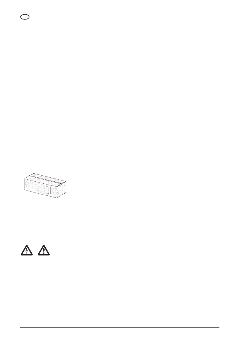
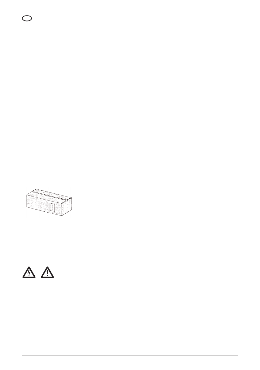
Il sollevamento della macchina può avvenire in una delle seguenti condizioni, macchina imballata con scatola di cartone.
3.1.1 MACCHINA IMBALLATA CON SCATOLA DI CARTONE
È possibile il sollevamento di più macchine imballate con una scatola di cartone in funzione del peso delle macchine.
3.2 TRASPORTO
Il trasporto della macchina deve avvenire nelle seguenti condizioni:
• Macchina in posizione orizzontale. • Macchina in posizione ssa senza
possibilità di movimenti
PERICOLO
Assicurarsi che le condizioni riportate nei punti precedenti siano rispettate durante il trasporto.
8
• Macchina protetta da agenti
atmosferici
Page 11
3.3 IMMAGAZZINAMENTO
3.3.1 CARATTERISTICHE DELLA ZONA DI IMMAGAZZINAMENTO
La zona di immagazzinamento deve presentare le seguenti caratteristiche siche:
IT
• Estensione suciente per contenere
la macchina con l'eventuale imballaggio
e consentire il sollevamento con i
mezzi di sollevamento previsti
• Supercie d'appoggio piana e
orizzontale
• Piano d'appoggio con portata
superiore al peso del numero delle
macchine immagazzinate
3.3.2 CARATTERISTICHE AMBIENTALI DELLA ZONA DI IMMAGAZZINAMENTO
La zona di immagazzinamento deve presentare le seguenti caratteristiche ambientali:
• Intervallo di temperatura ammesso: +7
°C ÷ +50 °C
• Intervallo di umidità relativa:
30 ÷ 90%
ATTENZIONE
Mantenere la macchina in posizione orizzontale.
3.4 VERIFICHE PRELIMINARI
3.4.1 CONTROLLO DEI DANNI
• Controllare l'integrità dell'eventuale
imballaggio
Vericare l'assenza di danni alla macchina, in particolare controllare l'integrità di:
• Copriventola del motore
• Coprimorsettiera
• Aprire l'eventuale imballaggio ed
estrarre la macchina
• Camicia esterna • Parti in ghisa
ATTENZIONE
Conservare l'eventuale imballo originale per un eventuale futuro trasporto della macchina.
• Protezione da eventuali urti accidentali
• Protezione da agenti atmosferici
• Vericare che la macchina ricevuta
corrisponda a quella richiesta
nell'ordine
3.4.2 SEGNALAZIONE DANNI
In caso di non corrispondenza o di danni, segnalare il problema a PENTAIR INTERNATIONAL S.a.r.l. o al rivenditore, entro e non oltre 8
(otto) giorni dalla data di acquisto.
3.5 PREPARAZIONE DELLA ZONA DI INSTALLAZIONE
3.5.1 CARATTERISTICHE DELLA ZONA DI INSTALLAZIONE
Il luogo di installazione della macchina deve avere le seguenti caratteristiche:
• Consentire il posizionamento e
l'accesso alla macchina in condizioni
agevoli
• Consentire un allacciamento sicuro
all'impianto elettrico
• Consentire collegamenti sicuri alle
tubazioni
• Presentare una illuminazione naturale
e/o articiale adeguata, che consenta
di operare con sicurezza
• Presentare una distanza minima di 150
mm tra ogni punto della macchina e un
qualsiasi ostacolo
• Garantire un'areazione suciente alla
ventola del motore
9
Page 12
IT
ATTENZIONE
Non coprire od ostruire la griglia copriventola del motore.
CONDIZIONI AMBIENTALI
• Intervallo di temperatura ammesso: +7
°C ÷ +50 °C
• Intervallo di umidità relativa ammesso:
30 ÷ 90%
• Protezione da agenti atmosferici
COLLEGAMENTO
Le tubazioni a cui collegare la macchina devono avere le seguenti caratteristiche:
• Diametri minimi di dimensioni
adeguate alla macchina
• Distanza e posizione tra le due
tubazioni come indicato nella “Scheda
prodotto” paragrafo “Dimensioni e pesi”
• Fissaggio a supporto sso, in maniera
da non scaricare tensioni e/o vibrazioni
sulla macchina
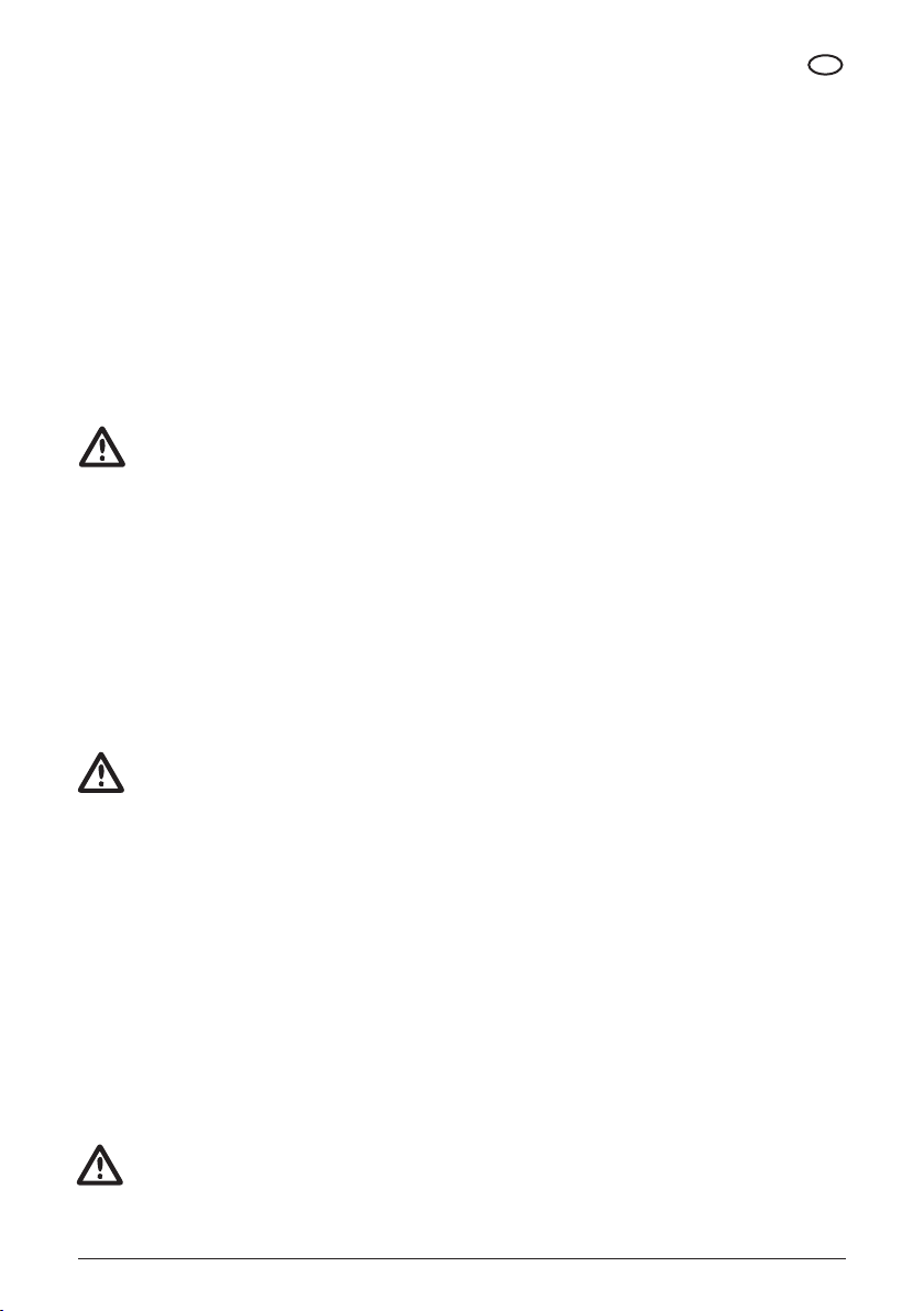
Se la macchina può funzionare con una valvola chiusa sulla tubazione di mandata, tubazione di ricircolo per la
salvaguardia della macchina con le seguenti caratteristiche:
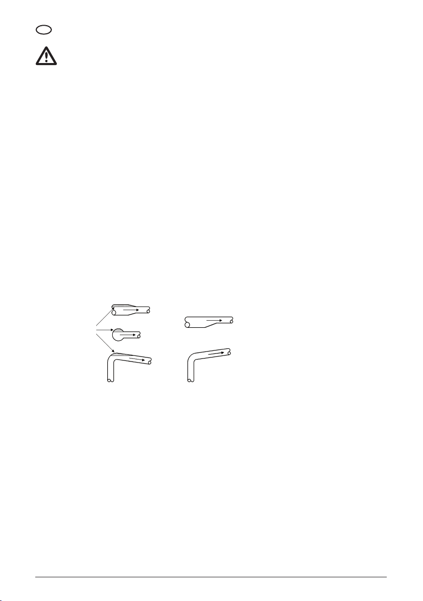
Non corretto
Sacche d'aria
• Assenze di sacche d'aria, come
indicato nella gura tubazioni
• Lunghezza della tubazione di
aspirazione ridotta al minimo
• Perdite di carico nella tubazione di
aspirazione ridotte al minimo (se la
macchina lavora in aspirazione. Vedi
“Macchine installate sopra battente”)
MONTAGGIO TUBAZIONI
Corretto
• Saracinesche sulle tubazioni di
mandata e aspirazione
• Se la macchina è montata sopra
battente, valvola di ritegno sulla
tubazione di aspirazione
• Se la macchina alimenta una caldaia,
valvola di ritegno sulla tubazione di
mandata
Collegamento tra:
• Tubazioni di mandata e aspirazione
• Tubazione di mandata e scarico
Controllo per mezzo di:
• Valvola termostatica
• Elettrovalvola azionata da pressostato
o da termo
ALIMENTAZIONE
La rete di alimentazione elettrica deve avere le seguenti caratteristiche:
• Presentare una protezione
differenziale
• Avere valori di tensione e frequenza
corrispondenti ai valori indicati
sulla targhetta dati del motore della
macchina
• Disporre di potenza erogabile non
inferiore al valore indicato sulla
targhetta dati del motore della
macchina
• Presentare un teleruttore con
protezione termica adeguata
• Presentare un relè termico
autocompensato e regolato in base alla
corrente reale assorbita
• Presentare un interruttore sezionatore
con fusibili di protezione
• Avere cavi di sezione suciente per la
corrente assorbita dal motore
ACCESSO
Collegare la macchina in un luogo che consenta un accesso agevole per le operazioni di manutenzione.
10
Page 13
SOSTEGNO
Il sistema di ssaggio della macchina può corrispondere ad uno dei seguenti schemi:
IT
• La macchina può essere collegata ad
una tubazione ssa che sia in grado di
mantenere in posizione la macchina
• La macchina può essere collegata
ad una tubazione e appoggiata ad un
piano con caratteristiche indicate
nella “Scheda prodotto” paragrafo
“Dimensioni e pesi”
• La macchina può essere collegata a
una tubazione e ssata tramite dadi ad
un piano con le caratteristiche indicate
nella “Scheda prodotto” paragrafo
“Dimensioni e pesi”
3.6 INSTALLAZIONE
PERICOLO
Tutte le operazioni relative all'installazione devono essere effettuate con l'elettropompa scollegata dalla rete di
alimentazione.
ATTENZIONE
Non installare l'elettropompa in locali dove sono presenti gas e/o materiali inammabili od esplosivi.
PERICOLO
Le elettropompe sono progettate in modo tale che tutte le parti in movimento sono rese inoffensive tramite l'uso di
protezioni. Non usare l'elettropompa con tali protezioni rimosse o danneggiate, possono causare gravi danni alle persone.
ATTENZIONE
Sulla linea di alimentazione dell'elettropompa deve sempre essere inserito un interruttore automatico differenziale.
In caso di installazione per uso con acqua potabile, eseguire un lavaggio della pompa prima della sua installazione, eseguire il lavaggio
anche in caso di prolungata inattività.
Nel caso di acqua potabile tutti i materiali utilizzati a monte e a valle della pompa devono essere conformi al contatto con acqua
destinata al consumo umano.
3.6.1 COLLEGAMENTO CON LE TUBAZIONI
Per collegare la macchina alle tubazioni, eseguire le seguenti operazioni:
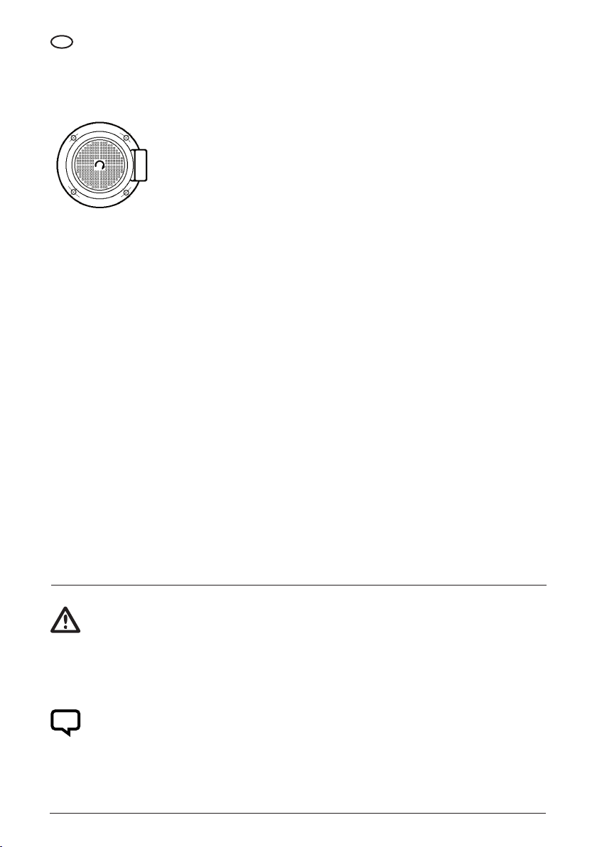
• Posizionare la macchina in modo
che le frecce presenti sulla base
corrispondano alla direzione di usso
del liquido
• Avvitare le estremità lettate delle
tubazioni alle bocche di
mandata/aspirazione inserendo del
teon come guarnizione.
3.6.2 ALLACCIAMENTO ALL'IMPIANTO ELETTRICO
MACCHINE CON MOTORI TRIFASE
PERICOLO
Sarà cura dell'installatore accertarsi che l'impianto di alimentazione elettrica sia provvisto di un eciente impianto di terra
secondo le vigenti normative.
PERICOLO
Occorre vericare che l'impianto di alimentazione elettrica sia dotato di un interruttore differenziale ad alta sensibilità
Δ = 30 mA (EN 61008-1 / EN 61009-1).
PERICOLO
Prima di rimuovere il coperchio della morsettiera del motore e prima di ogni intervento sull'elettropompa, accertarsi che la
linea di alimentazione sia stata sezionata.
Per allacciare la macchina all'impianto elettrico, eseguire le seguenti operazioni:
• Accertarsi che il motore sia adatto alla
tensione di rete
• Sezionare l'impianto elettrico tramite
interruttore sezionatore
• Svitare le viti che ssano il coperchio
della morsettiera
• Inserire il cavo di alimentazione nel
pressacavo
• Collegare le fasi e la terra ai morsetti
• Rimettere in posizione il coperchio
della morsettiera con la guarnizione
• Avvitare le viti che ssano il coperchio
morsettiera
• Inserire l'alimentazione elettrica
tramite l'interruttore sezionatore
• Dare un impulso di corrente alla
macchina
• Vericare il senso di rotazione del
motore
11
Page 14
IT
A - Se il senso di rotazione è concorde con il senso di rotazione indicato dalle frecce presenti sulla testa della macchina, i
collegamenti sono corretti.
B - Se il senso di rotazione è contrario al senso di rotazione indicato dalle frecce presenti sulla testa della macchina, eseguire le
seguenti operazioni:
• Sezionare l'impianto elettrico tramite
l'interruttore sezionatore
• Svitare le viti che ssano il coperchio
morsettiera
• Invertire il collegamento di due fasi
• Rimettere in posizione il coperchio
morsettiera con la guarnizione
• Avvitare le viti del coperchio
morsettiera
MACCHINE CON MOTORI MONOFASI
Per allacciare la macchina all'impianto elettrico, eseguire le seguenti operazioni:
• Accertarsi che il motore sia adatto alla
tensione di rete
• Sezionare l'impianto elettrico tramite
interruttore sezionatore
• Svitare le viti del coperchio
morsettiera
• Inserire il cavo di alimentazione nel
pressacavo
A - Se il senso di rotazione è concorde con il senso di rotazione indicato dalle frecce presenti sulla testa della macchina, i
collegamenti sono corretti
B - Se il senso di rotazione è contrario al senso di rotazione indicato dalle frecce presenti sulla testa della macchina,
eseguire le seguenti operazioni:
• Sezionare l'impianto elettrico tramite
interruttore sezionatore
• Svitare le viti che ssano il coperchio
morsettiera
• Collegare le linee e la terra
• Rimettere in posizione il coperchio
morsettiera con la guarnizione
• Avvitare le viti del coperchio
morsettiera
• Inserire l'alimentazione elettrica
tramite l'interruttore sezionatore
• Con un cavallotto cortocircuitare
momentaneamente i capi del
condensatore
• Cambiare la posizione dei ponticelli
• Dare un impulso di corrente alla
macchina
• Vericare il senso di rotazione
• Togliere il cavallotto
• Rimettere in posizione il coperchio
morsettiera con la guarnizione
• Avvitare le viti del coperchio
morsettiera
CAPITOLO 4
USO
ATTENZIONE
Non avviare mai la macchina prima di averla riempita di liquido, come indicato in "Uso", "Adescamento".
Prima di ogni utilizzo leggere il capitolo Impiego per un corretto uso.
4.1 ADESCAMENTO
NOTA
Una macchina viene considerata sotto battente se, in impianti a circuito chiuso o a circuito aperto, il livello del liquido da
pompare è posto superiormente alla bocca di aspirazione della macchina.
12
Page 15
4.1.1 MACCHINE INSTALLATE SOTTO BATTENTE
Per riempire una macchina sotto battente, eseguire le seguenti operazioni:
• Chiudere la saracinesca sulla
tubazione di mandata
Quando esce liquido, in maniera continua, dal tappo di adescamento, eseguire le seguenti operazioni:
• Svitare il tappo di adescamento • Aprire lentamente la saracinesca sulla
tubazione di aspirazione
IT
• Riavvitare il tappo di adescamento • Aprire completamente la saracinesca
sulla tubazione di aspirazione
• Aprire la saracinesca sulla tubazione
di mandata
PERICOLO
Assicurarsi del perfetto serraggio del tappo di adescamento e della valvola di sato.
4.1.2 MACCHINE INSTALLATE SOPRA BATTENTE (IN ASPIRAZIONE)
NOTA
Una macchina viene considerata sopra battente se, in impianti a circuito aperto, il livello del liquido da pompare è posto
inferiormente alla bocca di aspirazione della macchina.
Per riempire una macchina sopra battente, eseguire le seguenti operazioni:
• Aprire la saracinesca sulla tubazione di
aspirazione
• Chiudere la saracinesca sulla
tubazione di mandata
Quando non è più possibile riempire ulteriormente la macchina, eseguire le seguenti operazioni:
• Riavvitare il tappo di adescamento • Avviare la macchina • Aprire la saracinesca sulla tubazione
• Aprire il tappo di adescamento • Versare liquido nella macchina
attraverso il tappo di adescamento
no a quando non fuoriesce dal tappo
stesso
di mandata
PERICOLO
Assicurarsi del perfetto serraggio del tappo di adescamento e della valvola di sato.
4.2 AVVIAMENTO
Per il primo avviamento si consigliano le seguenti operazioni:
• Aprire la saracinesca sulla tubazione
di mandata
• Avviare la macchina
• Aprire lentamente la saracinesca
sulla tubazione di mandata per evitare
il colpo di ariete sulla tubazione di
mandata
• Regolare il relè termico in base alla
corrente assorbita dal motore della
macchina
• Regolare la pressione di attacco e
stacco dell'eventuale pressostato
che controlla il funzionamento della
macchina
13
Page 16
IT
4.3 CONTROLLO DELLA FREQUENZA DI AVVIAMENTI ED ARRESTI
Per controllare la frequenza di avviamenti ed arresti, eseguire le seguenti operazioni (seguire il funzionamento
della macchina per un'ora):
Se il numero di avviamenti/ora è superiore a 40, regolare le apparecchiature di controllo della macchina in modo da ridurre la frequenza.
ATTENZIONE
Controllare sempre il riempimento della macchina.
Non avviare mai la macchina prima di averla riempita di liquido, come indicato in "Uso", "Adescamento".
CAPITOLO 5
MANUTENZIONE
5.1 LUBRIFICAZIONE
• La tenuta sull'albero è autoregistrante.
Le superci di tenuta sono resistenti
all'usura e sono lubricate dal liquido
pompato
ATTENZIONE
Se le macchine vengono installate, utilizzate e mantenute seguendo le istruzioni e le indicazioni di questo manuale, non
necessitano di lubricazione. Seguire le istruzioni e le indicazioni di questo manuale.
5.2 DISATTIVAZIONE TEMPORANEA
Per disattivare la macchina per un lungo periodo di tempo, eseguire le seguenti operazioni.
Sezionare l'impianto elettrico mediante interruttore sezionatore, se esiste il rischio che la temperatura ambiente diventi
inferiore alla temperatura di congelamento del liquido pompato, eseguire le seguenti operazioni:
• I cuscinetti a strisciamento della
macchina sono lubricati dal liquido
pompato
• I cuscinetti a sfere del motore sono
autolubricati con grasso resistente
al calore
A - Se l'intero impianto deve essere disattivato, svuotare l'impianto.
B - Se l'intero impianto non deve essere disattivato:
• Chiudere le saracinesche sulle
tubazioni di mandata e aspirazione
• Togliere il tappo di adescamento e
il tappo di spurgo e scarico (dove
presente)
• Lasciare deuire tutto il liquido dalla
macchina
• Conservare il tappo di adescamento ed
il tappo di spurgo e scarico no ad un
nuovo utilizzo della macchina, senza
rimontare i due tappi sulla macchina.
ATTENZIONE
Prima di rimettere in funzione la macchina effettuare il riempimento della macchina, come indicato in "Uso", "Adescamento".
Se l'elettropompa viene utilizzata per installazioni con acqua destinata ad uso umano e resta inutilizzata per lunghi periodi, prima
dell'uso ripetere le procedure indicate nel capito Installazione.
5.3 ISPEZIONE PERIODICA
Ad intervalli regolari effettuare i controlli seguenti:
• Prestazioni idrauliche
• Assenza perdite liquido
• Surriscaldamento motore
14
• Tempo intervento relè
• Frequenza avviamenti
• Funzionamento corretto comandi
automatici
• Vibrazioni
• Rumore
Page 17

A - Se i controlli non rivelano niente di anomalo, continuare l'utilizzo della macchina no a nuovo controllo.
B - Se i controlli rivelano qualcosa di anomalo, eseguire le seguenti operazioni:
IT
• Consultare la tabella "Difetto/Cause" in
"Problemi di funzionamento"
• Se si riscontra il difetto e la causa nella
tabella "Difetto/Cause" in "Problemi di
funzionamento", chiamare un tecnico
autorizzato o un tecnico specializzato
e indicargli la causa del difetto
riscontrato
• Se non si riscontra il difetto e la
causa nella tabella "Difetto/Cause" in
"Problemi di funzionamento", chiamare
un tecnico autorizzato o un tecnico
specializzato
5.4 MANUTENZIONE STRAORDINARIA
Per le operazioni di manutenzione straordinaria, in seguito a malfunzionamenti, guasti, rotture o aggiornamenti tecnici, interpellare
esclusivamente un tecnico autorizzato o tecnico specializzato.
NOTA
PENTAIR INTERNATIONAL S.a.r.l. declina ogni responsabilità e recide ogni contratto di garanzia nel caso di:
• Operazioni non documentate in questo manuale ed effettuate sulla macchina
• Operazioni di manutenzione straordinaria effettuate da personale diverso dal tecnico autorizzato o specializzato
CAPITOLO 6
PROBLEMI DI FUNZIONAMENTO
DIFETTO CAUSE
1) La tensione di linea è interrotta.
2) Fusibile bruciato.
IL MOTORE NON GIRA ALL'AVVIAMENTO
IL TERMICO DEL MOTOAVVIATORE INTERVIENE
QUANDO SI DÀ TENSIONE
IL RELÈ TERMICO SCATTA OCCASIONALMENTE
SENZA APPARENTE MOTIVO
IL RELÈ TERMICO NON È INTERVENUTO
MA LA MACCHINA NON FUNZIONA
3) Il relè termico è scattato.
4) I contatti del motoavviatore non conducono o la bobina è difettosa.
5) I fusibili del circuito ausiliario sono bruciati.
6) Il motore della macchina è difettoso.
1) Fusibile bruciato.
2) I contatti del motoavviatore sono difettosi.
3) I collegamenti elettrici sono difettosi.
4) Gli avvolgimenti del motore sono difettosi.
5) La macchina è meccanicamente bloccata.
6) La taratura del relè termico è troppo bassa.
1) La taratura del relè termico è troppo bassa.
2) La tensione di linea manca periodicamente.
3) La tensione di linea nei periodi di punta è troppo bassa.
1) La tensione di linea è interrotta.
2) Fusibile bruciato.
3) I contatti del motoavviatore non conducono o la bobina è difettosa.
4) I fusibili del circuito ausiliario sono bruciati.
15
Page 18
IT
DIFETTO CAUSE
LA PORTATA DELLA MACCHINA NON È COSTANTE
LA MACCHINA FUNZIONA MA NON EROGA LIQUIDO
AL MOMENTO DELL'ARRESTO
LA MACCHINA GIRA AL CONTRARIO
CAPITOLO 7
DEMOLIZIONE
7.1 DISATTIVAZIONE DELLA MACCHINA
1) Il tubo di aspirazione è sottodimensionato.
2) La disponibilità di liquido in aspirazione non è suciente.
3) Il livello del liquido è troppo basso.
4) La pressione battente è insuciente.
5) Il tubo di aspirazione è parzialmente ostruito.
1) Il tubo di aspirazione o la pompa sono ostruiti.
2) La valvola di fondo (o di ritegno) è bloccata in posizione chiusa.
3) Nel tubo aspirante ci sono delle perdite.
4) Nella tubazione di aspirazione o nella pompa è presente dell'aria.
1) Nel tubo aspirante ci sono delle perdite.
2) La valvola di fondo (o di ritegno) è difettosa.
3) La valvola di fondo (o di ritegno) è bloccata in posizione di parziale o totale apertura.
• Sezionare l'impianto elettrico tramite
interruttore sezionatore
• Chiudere le saracinesche sulle
tubazioni di aspirazione e mandata
• Svitare le viti che ssano il coperchio
morsettiera
• Scollegare i li dai morsetti
Se la macchina deve essere riutilizzata, eseguire le seguenti operazioni:
• Riavvitare il tappo di adescamento
e il tappo di spurgo e scarico sulla
macchina
• Rimettere in posizione il coperchio
• Slare il cavo di alimentazione dal
pressacavo
• Togliere il tappo di adescamento e il
tappo di scarico.
• Lasciare deuire tutto il liquido dalla
macchina
• Svitare le viti che eventualmente
ssano la macchina al piano di
appoggio
morsettiera con la guarnizione
• Avvitare le viti che ssano il coperchio
morsettiera
• Chiudere i fori di mandata e di
aspirazione in modo che non possa
entrare sporco nella macchina
• Sollevare la macchina come indicato in
"Installazione", "Sollevamento"
• Trasportare la macchina come indicato
in "Installazione", "Trasporto"
• Immagazzinare la macchina
come indicato in "Installazione",
"Immagazzinamento"
NOTA
PENTAIR INTERNATIONAL S.a.r.l. declina ogni responsabilità in caso di riciclaggio o riutilizzo di parti della macchina.
7.2 RISCHI RESIDUI DOPO LA DISATTIVAZIONE
ATTENZIONE
La macchina è realizzata con materiali non biodegradabili. Portare la macchina in un deposito attrezzato per lo smaltimento.
16
Page 19
SUMMARY
CHAPTER DESCRIPTION PAGE
1.1 Documentation supplied 18
1.2 Ownership of information 18
1.3 Machine identication data 18
1.4 EC compliance declaration 18
1
2 DESCRIPTION
3 INSTALLATION
4 OPERATION
5 MAINTENANCE
6 OPERATING PROBLEMS Table 31
7 DEMOLITION
-
- WARRANTY - 116
GENERAL
INFORMATION
PRODUCT
SPECIFICATION
1.5 General safety information 19
1.6 Conventions 21
1.7 Recommended use 21
1.8 Non recommended use 22
1.9 Warranty 23
1.10 Assistance 23
1.11 How to use the documentation supplied 23
2.1 Description 23
2.2 Technical characteristics 24
3.1 Lifting 24
3.2 Transportation 24
3.3 Storage 25
3.4 Preliminary inspections 25
3.5 Preparation of the installation site 25
3.6 Installations 27
4.1 Priming 28
4.2 Start-up 29
4.3 Checking the frequency of starts and stops 30
5.1 Lubrication 30
5.2 Temporary disabling 30
5.3 Periodical inspection 30
5.4 Extraordinary maintenance 31
7.1 Machine disabling 32
7.2 Residual risks after disabling 32
- 113
EN
17
Page 20

EN
CHAPTER 1
GENERAL INFORMATION
1.1 DOCUMENTATION SUPPLIED
1.1.1 MANUAL
This manual is addressed to the operators responsible for operating the machine during all the technical stages of its life.
This manual is an integral part of the product and must be consulted before rst use and to ensure correct use and maintenance.
CONTENTS
This manual contains the following information:
• Manufacturer’s declaration
• Safety information
• Commercial information
• Information on documentation
Le informazioni sono suddivise nei seguenti capitoli e appendici di questo manuale:
• Chapter 1: General information
• Chapter 2: Description
• Chapter 3: Installation
• Machine description
• Transportation information
• Storage information
• Installation information
• Chapter 4: Operation
• Chapter 5: Maintenance
• Chapter 6: Operating problems
• Information on adjustments
• Operational information
• Maintenance information
• Dismantling information
• Chapter 7: Dismantling
• Appendix: Product specications
1.2 OWNERSHIP OF INFORMATION
The information contained in this manual is property of PENTAIR INTERNATIONAL S.a.r.l.
It is forbidden to reproduce in whole or in part this manual without the explicit authorisation of PENTAIR INTERNATIONAL S.a.r.l.
The information contained in this manual is related only to the machines indicated in section “Product Specications”.
PENTAIR INTERNATIONAL S.a.r.l. reserves the right to make the changes deemed necessary to the machines not listed in the
“Machine identication data”.
1.3 MACHINE IDENTIFICATION DATA
MACHINE CODE DESCRIPTION
DHR Horizontal multi-stage centrifugal electropump.
4- Rated ow rate m
50 Number of stages x 10
3
/h
1.4 EC COMPLIANCE DECLARATION
See page
18
Page 21
EN
1.5 GENERAL SAFETY INFORMATION
It is advisable to carefully follow the instructions contained in this manual with specic reference to notes, warnings and danger signs.
DANGER
This appliance is not intended for use by persons (including children) with reduced physical, sensory or mental capabilities,
or lack of experience and knowledge, unless they have been given supervision or instruction concerning use of the
appliance by a person responsible for their safety.
Children should be supervised to ensure that they do not play with the appliance.
WARNNG
Users should always follow the accident prevention laws in force in the country
where the product is installed.
DANGER
Before repairing or servicing the electropump, disconnect it from the socket and/or turn the main switch to Off (when
present) to interrupt the power supplied to the electropump. This prevents the electropump from accidentally restarting
and from causing accidents to people and/or damages to the people.
DANGER
Do not service, install or move the electropump while it is powered, because these operations can cause serious accidents
or even death.
WARNNG
During operation, do not remove or move the electropump.
DANGER
Before using the electropump, always check that the cable and all electric devices are ecient, shielded and protected.
DANGER
When starting the electropump (by inserting the plug into the socket and/or turning the main switch to on), always wear
shoes and make sure that the hands are dry.
NOTE
Failure to follow the safety procedures and precautions contained in the documentation supplied shall relieve PENTAIR
INTERNATIONAL S.a.r.l. from all liability thereof.
All materials in contact with water have been tested and approved, therefore only original replacement parts should be used.
19
Page 22

EN
1.5.1 PERSONNEL QUALIFICATIONS
Qualication and protection limits established for operators
OPERATOR QUALIFICATION RECCOMENDED INDIVIDUAL PROTECTION MEAN
Knowledge and command of the chapters:
CARRIER
INSTALLER
USER
MAINTENANCE MAN
DEMOLISHER
DANGER
The machine operates in safety conditions if it is used by qualied personnel in accordance with the instructions and
information contained in this manual and present on board.
All the operations referred to in this manual should be performed by qualied personnel equipped with the protection means
described in this manual.
NOTE
PENTAIR INTERNATIONAL S.a.r.l. shall not be liable for accidents if the machine is used from non qualied or unauthorised
personnel and originating from the failure to follow the instructions contained in this manual and present on the machine
board.
• General information
• Description
• Installation
Qualication complying with the provisions of the Country of
installation,
knowledge and command of the chapters:
• General information
• Description
• Installation
Knowledge and command of the chapters:
• General information
• Description
• Use
Fitness acknowledged by PENTAIR INTERNATIONAL S.a.r.l.,
knowledge and
command of the chapters:
• General information
• Description
• Maintenance
Knowledge and command of the chapters:
• General information
• Description
• Dismantling
Protective shoes and gloves.
Protective shoes and gloves.
Protective shoes and gloves, high temperature protecting overall
and gloves.
Protective shoes and gloves.
Protective shoes and gloves.
20
Page 23
1.5.2 SPECIAL MEASURES
The use of personnel with a qualication differing from the one indicated can endanger the safety of people and/or damage the
property.
CONVENTIONS
1.6.1 TERMINOLOGICAL CONVENTIONS
The following conventions have been adopted throughout the manual
EN
• Machine: elettropompe specicate in
"Scheda prodotto"
• Authorised technician:
person authorised by PENTAIR
INTERNA TIONAL to perform even the
operations not specically indicated in
this manual
• Specialised technician: person
authorised to perform even the
operations not specically indicated in
this manual after being authorised by
PENTAIR INTERNATIONAL
1.6.2 TYPESETTING CONVENTIONS
DANGER
Le indicazioni di pericolo indicano quelle procedure la cui mancata o parziale osservanza può produrre danni sici
all'operatore.
WARNNG
Le indicazioni di attenzione indicano quelle procedure la cui mancata o parziale osservanza può produrre danni alla
macchina o alle apparecchiature ad essa collegate.
NOTE
Le indicazioni di nota contengono delle informazioni, importanti, evidenziate al di fuori del testo a cui si riferiscono.
1.7 RECOMMENDED USE
1.7.1 RECOMMENDED USE
The machine has been designed, manufactured and protected to allow the transfer, circulation and increase of pressure of the
following types of liquid:
• Water with temperature ranging
between +10 °C and 90 °C up to 6 bar,
50°C up to 10 bar
• Fluids with a viscosity similar to water,
neutral and non-explosive uids
Note
The pump is suitable for use with drinking water for human consumption (Italian Ministerial Decree 174 and ACS). If the pump has been
assigned to uses other than water for human consumption, it may no longer subsequently be used for that purpose.
• The machine has been designed,
manufactured and protected to
guarantee a ow rate of uid that
changes according to the desired head
(see “Product specications”)
• The pump must not be used for acids
or corrosive substances
21
Page 24

EN
1.7.2 RECOMMENDED INSTALLATION
The machine has been designed, manufactured and protected to be installed in the following environments:
• Indoors
The machine has been designed, manufactured and protected to be used in the following atmospheric conditions:
• Temperature range:
-10 °C and +50 °C
The machine has been designed, manufactured and protected to be:
• Outdoors with protection against
atmospheric agents
• Relative humidity range:
from 30% to 90%
• Installed horizontally on a at
foundation with dimensions at least
equal to the maximum length and
width of the pump. For the pump
dimensions refer to the appendix
“Product specications”, section
“Dimensions and weights”
The machine has been designed, manufactured and protected to be supplied with electric energy having the following characteristics:
• 230 V, 50 Hz, single-phase
Different voltage and frequency values are available on request.
• Permanently xed on the at
foundation using the 4 bolt holes in
the motor support and corresponding
bolts with thread lock nuts in order
to avoid loosening due to vibrations
produced by the pump in service
• 230 V, 50 Hz, three-phase • 400 V, 50 Hz, three-phase
• Fixed to tubing able to sustain the
machine weight
1.8 NON RECOMMENDED USE
The machine has not been designed, manufactured or protected for the uses not specically listed under section “Recommended
use”. In particular the machine has not been designed, manufactured or protected to transfer, circulate or increase the pressure of the
following uids:
• Explosives
• Corrosive uids
For special uses, contact our technical department
• Fluids derived from crude oil or
mixtures containing derivatives of
crude oil
• Mixtures containing materials or
suspended bres
• Sea water
1.8.1 LIABILITY ARISING FROM NON RECOMMENDED USE
NOTE
PENTAIR INTERNATIONAL S.a.r.l. shall not be liable for damages to people, animals or property deriving from non
recommended use
22
Page 25
1.9 WARRANTY
NOTE
Installation, adjustment and maintenance operations that have not been authorised and/or performed by unskilled
personnel will invalidate the warranty.
1.10 ASSISTANCE
WARNNG
If the pump has been used with noxious or toxic uids, the pump will be classied as polluted and PENTAIR INTERNATIONAL
S.a.r.l. will have the right to refuse offering its assistance for the pump.
For all assistance requests, contact:
PENTAIR INTERNATIONAL Sarl – Servizio Assistenza
Via Masaccio, 13
56010 Lugnano - PISA - ITALY
Tel. 050/71.61.11 - Fax 050/70.31.37
1.11 HOW TO USE THE DOCUMENTATION SUPPLIED
Operators should carefully read the documentation supplied before performing any operation on the machine.
The documentation supplied should be kept along with the machine until it is dismantled, so that it is available in case of need.
If the used machine is sold, it will be necessary to supply all the documentation enclosed.
CHAPTER 2
DESCRIPTION
2.1 DESCRIPTION
2.1.1 ARCHITECTURE AND OPERATING PRINCIPLES
EN
• DHR electropumps are horizontal
centrifugal multi-stage electropumps
with suction and delivery mouths
arranged at 90°
2.1.2 MACHINE FRAME
• The suction ange and the pump
casing of electropumps DHR are in cast
iron GG20
• The shaft, the impellers and the
diffusers of electropumps DHR are in
stainless steel AISI 304
• DHR electropumps are directly coupled
to an asynchronous electric motor or
to a three-phase motor with closed
casing and external ventilation
• The mechanical seals of electropump
DHR are constituted by sliding
backfaces in graphite/ceramics
• DHR electropumps are self-priming
and don’t require a priming procedure
• The gaskets of electropumps DHR are
in NBR rubber and paper
23
Page 26
EN
2.2 TECHNICAL CHARACTERISTICS
• Dimensions and weights of machines:
See "Product Specications”,
paragraph “Dimensions and weights”
• Electric data:
See "Product Specications”,
paragraph “Electric suply” and
identication nameplate
• Pressure:
maximum operating pressure: 6 bar
(90°C) or 10 bar (50°C)
2.2.1 NOISE
The maximum continuous noise equivalent to weighed noise A of acoustic vibrations generated by the machine: 82 dB (A)
2.2.2 LIABILITY
PENTAIR INTERNATIONAL S.a.r.l. declines any liability in the event of failure to comply with the values indicated in this paragraph.
CHAPTER 3
INSTALLATION
3.1 LIFTING
The machine can be lifted in the following condition, machine packed in a cardboard box.
3.1.1 MACHINE WITHOUT ANY TYPE OF PACKING
It is possible to lift several machines packed in a cardboard box, depending on the machine weight.
3.2 TRANSPORTATION
The machine must be transported in the following conditions:
• Machine in horizontal position. • Machine in xed position without
possibility of moving
DANGER
Ascertain that the conditions referred to in the points above are met during transportation.
24
• Machine protected from atmospheric
agents
Page 27
3.3 STORAGE
3.3.1 CHARACTERISTICS OF THE STORAGE AREA
The storage area should have the following physical characteristics:
EN
• Sucient extension to contain the
machine and the packing, when
present, and to enable its lifting by
means of the lifting devices provided
• Flat and horizontal resting surface
• Resting surface with a capacity above
the weight of the machines stored
• Protection against accidental impacts
3.3.2 ENVIRONMENTAL CHARACTERISTICS OF THE STORAGE AREA
The storage area should have the following environmental characteristics:
• Acceptable temperature range:
+7 °C ÷ +50 °C
• Relative humidity range: 30 ÷ 90%
• Protection from atmospheric agents
WARNNG
Mantenere la macchina in posizione orizzontale.
3.4 PRELIMINARY INSPECTIONS
3.4.1 ASSESSMENT OF DAMAGE
• Check the integrity of the packing • Open the packing and extract the
Check that the machine has not suffered damage, and verify in particular that the following components are integral:
• Motor fan cover
• Terminal block cover
machine
• Intermediate chambers • Cast iron parts
• Check that the received machine
complies with the characteristics
indicated in the order
WARNING
Keep the original packing in the event it were necessary to transport the machine in future.
3.4.2 DAMAGE REPORTING
If non compliance characteristics or damages are detected, immediately report the problem to PENT AIR INTERNATIONAL or to the
distributor within and no later than 8 (eight) days from the date of purchase.
3.5 PREPARATION OF THE INSTALLATION SITE
3.5.1 CHARACTERISTICS OF THE INSTALLATION SITE
The installation site should have the following characteristics:
• Simplify the positioning and access to
the machine
• Enable a safe connection to the
electric system
• Enable safe connections to tubing
• Offer an appropriate natural and/or
lighting designed to guarantee full
operational safety
• Offer a minimum distance of 150 m
from each point of the machine and
from obstacles
• Guarantee a sucient ventilation for
the motor fan
WARNING
Do not cover or obstruct the motor fan cover grid.
25
Page 28
EN
ENVIRONMENTAL CONDITIONS
• Acceptable temperature range:
+7 °C ÷ +50 °C
• Acceptable relative humidity range:
30 ÷ 90%
• Protection from atmospheric agents
CONNECTION
The pipes used to connect the machine should have the following characteristics:
• Minimum diameters with dimensions
suited to the machine
• The distance and position of the
two pipes should comply with the
indications given in
"Product specications”, paragraph
“Dimensions and weights”
• Anchoring to xed support in order not
to exert tension and/or vibrations on
the machine
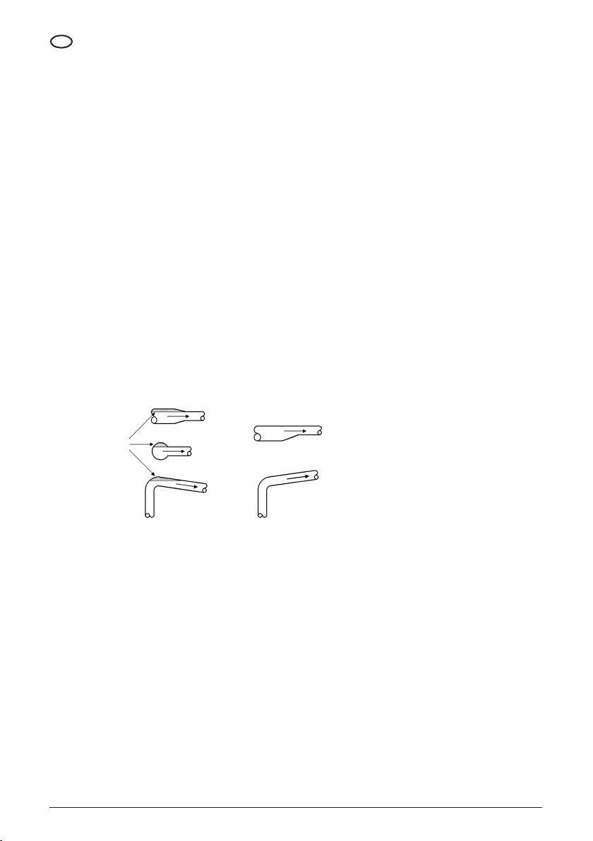
If the machine is designed to operate with a closed valve on the delivery line, a recirculation pipe should be provided for protection
purposes. The pipe should have the following characteristics:
Incorrect Correct
Accumulated air
• Lack of air locks, as shown in the
piping gure
• Suction pipe length reduced to a
minimum
• Load losses in the suction pipe
reduced to a minimum (if the machine
is used to suck uid, see “Machines
installed above the water level”)
• Gates on the delivery and suction line
PIPE ASSEMBLY
• If the machine is installed above water
level, a stop valve should be tted on
the suction line
• If the machine supplies a boiler, a
stop valve should be tted on the
delivery line
Connection between:
• Delivery and suction line
• Delivery and drainage pipe
Controls should be performed by means
of:
• Thermostatic valve
• Solenoid valve driven by a pressure
switch or a thermostat
POWER SUPPLY
Electric power supply should have the following characteristics:
• Offer a differential protection
• Offer voltage and frequency values
compliant with the values indicated on
the motor nameplate
• Offer a power not below the value
indicated on the motor nameplate
• Be equipped with an appropriate
thermal protection
• Be equipped with a thermal relay
adjusted according to the actual
current absorbed
ACCESS
Connect the machine so that it can be easily accessible for maintenance operations.
26
• Be equipped with a cut-off switch with
protective fuses
• Be equipped with cables with a section
suitable to the power absorbed by
the motor
Page 29

SUPPORTING SYSTEM
The machine supporting system can correspond to one of the following congurations:
EN
• The machine can be connected to a
xed pipe able to maintain the machine
in position
• The machine can be connected to a
pipe and rested on a base having the
characteristics indicated in “Product
specications” under paragraph
“Dimensions and weights”
• The machine can be connected to
a pipe and xed, by means of nuts,
to a base having the characteristics
indicated in “Product specications”,
paragraph “Dimensions and weights”
3.6 INSTALLATIONS
DANGER
All installation operations should be performed while the electropump is disconnected from the mains.
WARNING
Do not install the machine in environments containing gases and/or inammable or explosive materials.
DANGER
Electropumps are designed so that all the moving parts are rendered inoffensive by means of protections.
Do not use the electropump if these protections have been removed or are damaged, since this could cause serious
accidents to people.
WARNING
The machine supply line should always have a differential circuit breaker.
If installed for use with drinking water, clean the pump prior to installation - also clean if left unused for prolonged periods of time.
For drinking water, all materials used upstream and downstream of the pump must also be suitable for contact with drinking water for
human consumption
3.6.1 CONNECTION OF THE MACHINE TO THE PIPES
To connect the machine to the pipes, perform the following operations:
• Position the machine so that the
arrows present on the base correspond
to the direction of the uid ow
• Tighten the threaded ends of the pipes
to the delivery/suction mouths using T
eon as sealing material
3.6.2 CONNECTION TO THE MAINS
MACHINES WITH THREE-PHASE MOTORS
DANGER
The installer will have to make sure that the electric supply system has an adequate grounding compliant with the laws in
forc e.
WARNING
Check that the supply system has a differential switch with a degree of sensitivity of
Δ = 30 mA (EN 61008-1 / EN 61009-1).
DANGER
Before removing the cover from the terminal block of the motor and before performing operations on the machine, make
sure that the supply line has been cut-off.
To connect the machine to the mains, perform the operations described here below:
• Make sure that the motor is suitable to
the mains voltage and frequency
• Cut the electric system off by using a
cut-off switch
• Loosen the screws that x the cover to
the terminal block
• Insert the supply cable into the cable
holder
• Connect the phases and ground to the
terminals
• Reposition the cover of the terminal
block with the related gasket
• Tighten the screws that x the cover to
the terminal block
• Supply the machine with the cut-off
switch
• Supply one current impulse and check
the direction of rotation of the motor
27
Page 30

EN
A - If the direction of rotation complies with the direction of the rotation indicated by the arrows shown on the machine head, the
connections are correct
B - If the direction of rotation is opposed to the one shown by the arrows present on the machine head, perform the following
operations:
• Cut the electric system off by using the
cut-off switch
• Loosen the screws that x the terminal
block cover in position
• Invert the connection of the two
phases
• Reposition the terminal block cover
with the related gasket
• Tighten the screws of the terminal
block cover
MACHINES WITH SINGLE-PHASE MOTORS
To connect the machine to the mains, perform the operations described here below:
• Make sure that the motor is suitable to
the mains voltage and frequency
• Cut the electric system off by using a
cut-off switch
• Loosen the screws that x the cover to
the terminal block
• Insert the supply cable into the cable
holder
A - If the direction of rotation complies with the direction of the rotation indicated by the arrows shown on the machine head, the
connections are correct
B - If the direction of rotation is opposed to the one shown by the arrows present on the machine head, perform the following
operations:
• Cut the electric system off by using the
cut-off switch
• Loosen the screws that x the terminal
block cover in position
• Connect the lines to the grounding
system
• Reposition the cover of the terminal
block with the related gasket
• Tighten the screws that x the cover to
the terminal block
• Use a bolt to temporarily short-circuit
the ends of the condenser
• Change the position of the bridges
• Insert the electric supply by using the
cut-off switch
• Supply one current impulse to the
machine
• Check the direction of rotation of the
motor
• Remove the bolt
• Reposition the terminal block cover
with the related gasket
• Tighten the screws of the terminal
block cover
CHAPTER
OPERATION
WARNING
Always start the machine after lling it with uid, as explained under sections “Operation” and “Priming”.
Before using the pump, read Application chapter for a proper use.
4.1 PRIMING
NOTE
A machine is considered below the water level if the level of the uid to pump is above the suction mouth of the machine,
both with closed or open loop systems.
28
Page 31

4.1.1 MACHINES INSTALLED BELOW THE WATER LEVEL
To ll a machine below the water level, perform the following operations:
• Close the gate on the delivery line • Loosen the priming cap • Slowly open the gate on the suction
When the uid starts to exit from the priming cap, preform the following operations:
• Re-tighten the priming cap • Fully open the gate on the suction line • Open the gate on the delivery line
line
DANGER
Make sure the priming cap is perfectly tightened.
4.1.2 MACHINES INSTALLED ABOVE THE WATER LEVEL (ON THE SUCTION SIDE)
NOTE
A machine is considered above the water level if the level of the uid to pump is below the suction mouth of the machine,
both with closed or open loop systems.
To ll a machine above the water level, perform the following operations:
EN
• Open the gate on the suction line
• Close the gate on the delivery line
When it is no longer possible to add futher uid, perform the following operations:
• Re-tighten the priming cap • Start the machine • Open the gate on the delivery line
• Open the priming cap • Add the uid through the priming cap
until it starts to come out from the cap
DANGER
Make sure the priming cap is perfectly tightened.
4.2 START-UP
Perform the following operations to start the machine for the rst time:
• Open the gate on the suction line
• Start the machine
• Slowly open the gate on the delivery
line to avoid water hammering on the
delivery line
• Adjust the thermal relay depending on
the current absorbed by the motor
• Adjust the enabling and disabling
pressure of the pressure switch that
controls the operation of the machine
29
Page 32

EN
4.3 CHECKING THE FREQUENCY OF STARTS AND STOPS
To check the frequency of starts and stops, perform the following operations (Check the operation of the machine for an hour):
If the number of starts/stops is above 40, adjust the control equipment in order to reduce the frequency.
WARNING
Always check that the machine is lled. Never start the machine without uid, as indicated under section “Operation”,
“Priming”
CHAPTER 5
MAINTENANCE
5.1 LUBRICATION
• The gasket on the shaft is self-
adjusting. The sealing surfaces are
resistant to wear and are lubricated by
the pumped uid
WARNING
If the machines are installed, used and serviced in accordance with the instructions and directions given in this manual,
they do not require lubrication. Follow the instructions and directions given in this manual.
• The bearings of the machine are
lubricated by the pumped uid
5.2 TEMPORARY DISABLING
To disable the machine for a long period of time, perform the following operations.
Cut the electric system off by using a cut-off switch, if ambient temperature falls below the freezing temperature
of the pumped uid, perform the following operations:
• The ball bearings of the motor are
self-lubricated with grease resistant
to heat
A - If the whole system has to be disabled, drain the system
B - If it is not necessary to drain the whole system:
• Close the gates on the delivery and
suction lines
• Remove the priming and drainage caps
• Allow all the uid to drain from the
machine
• Store the priming and drainage caps
for future use, without reassembling
them on the machine
WARNING
Before restarting the machine, ll it as indicated under sections “Operation” and “Priming”
If the pump is used for applications with drinking water for human consumption and it is not used for a long period, repeat the
procedures listed in Installation chapter.
5.3 PERIODICAL INSPECTION
Ad intervalli regolari effettuare i controlli seguenti:
• Hydraulic performances
• Lack of uid leaks
• Motor overheating
30
• Relay tripping time
• Start-up frequency
• Correct operation of automatic
controls
• Vibrations
• Noise
Page 33

A - If check-ups do not reveal the presence of abnormal conditions, continue to use the machine until the next check-up
B- If check-ups reveal the presence of abnormal conditions, perform the operations described here below:
EN
• Refer to table “Problems/Causes" under
"Operating problems"
• If the problem and cause is listed in
table
• “Problems/Causes” under “Operating
problems”, contact an authorised
technician or a specialised technician
and report the abnormal condition
found
• If the problem and the cause is not
listed in table “Problems/Causes” under
“Operating problems”, contact an
authorised technician or a specialised
technician.
5.4 EXTRAORDINARY MAINTENANCE
Extraordinary maintenance operations performed after problems, failures, breakage or technical updates should be performed only by
authorised or specialised technicians.
NOTE
PENTAIR INTERNATIONAL S.a.r.l. declines any liability and cancels all warranty contracts in presence of:
• Operations not documented in this manual and performed on the machine.
• Extraordinary maintenance carried out by others than authorised or specialised technicians.
CHAPTER 6
OPERATING PROBLEMS
PROBLEM CAUSES
1) The line voltage has been interrupted.
2) Burnt fuse.
THE MOTOR FAILS TO RUN WHEN STARTED
THE STARTER THERMAL SWITCH TRIPS
WHEN VOLTAGE IS APPLIED
THE THERMAL RELAY TRIPS OCCASIONALLY
WITHOUT APPARENT REASON
THE THERMAL RELAY HAS NOT TRIPPED,
BUT THE MACHINE IS UNABLE TO RUN
3) Tripped thermal relay.
4) No conduction in the starter contacts or faulty coil.
5) Burnt fuses in the auxiliary circuit.
6) Faulty motor.
1) Burnt fuse.
2) Faulty starter contacts.
3) Faulty electric connections.
4) Faulty motor windings.
5) The machine is mechanically blocked.
6) The thermal relay calibration is too low.
1) The thermal relay calibration is too low.
2) The line voltage is periodically missing.
3) The line voltage in peak periods is too low.
1) The line voltage has been interrupted.
2) Burnt fuse.
3) No conduction in the starter contacts or faulty coil.
4) Burnt fuses in the auxiliary circuit.
31
Page 34

EN
PROBLEM CAUSES
THE MACHINE FLOW RATE IS IRREGULAR
THE MACHINE RUNS BUT FAILS TO SUPPLY FLUID
WHEN STOPPED THE MACHINE
RUNS IN OPPOSITE DIRECTION
CHAPTER 7
DEMOLITION
7.1 MACHINE DISABLING
1) The suction pipe is undersized.
2) The availability of uid to be sucked is insucient.
3) The uid level is too low.
4) The pressure on the suction side is insucient.
5) The suction pipe is partially obstructed.
1) The suction pipe or pump are obstructed.
2) The bottom (or stop) valve is blocked in closed position.
3) Leaks in the suction line.
4) Air in the suction line or pump.
1) Leaks in the suction pipe.
2) Faulty bottom (or stop) valve.
3) The bottom (or stop) valve is blocked in partially or fully opened position.
• Cut the system off using the cut-off
switch
• Close the gates on the suction and
delivery lines
• Loosen the screws that x the terminal
block cover
• Disconnect the wires from the terminal
block
To re-use the machine, perform the following operations:
• Reposition the priming and drainage
caps on the machine
• Reposition the terminal block cover
with the related gasket
NOTE
PENTAIR INTERNATIONAL S.a.r.l. shall not be liable of parts of the machine are recycled or re-used.
• Remove the supply cable from the
cable holder
• Remove the priming and drainage caps
• Allow all the uid to drain from the
machine
• Loosen the screws that x the
machine to the base
• Tighten the screws that x the
terminal block cover
• Close the delivery and suction holes to
prevent dirt from entering inside the
machine
• Lift the machine as described under
"Installation", "Lifting" -Transport
the machine as indicated under
"Installation", "Transportation"
• Store the machine as indicated in
“Installation”, “Storage”
7.2 RESIDUAL RISKS AFTER DISABLING
WARNING
The machine has been manufactured with non biodegradable materials. The machine should be dismantled only in a deposit
equipped for these operations.
32
Page 35

TABLE DES MATIÈRES
CHAPITRE DESCRIPTION PAGE
1.1 Documentation fournie 34
1.2 Proprieté des informations 34
1.3 Données identication de la machine 34
1.4 Déclaration CE de conformité 34
1
2 DESCRIPTION
3 INSTALLATION
4 UTILISATION
5 MAINTENANCE
6
7 DEMOLITION
- FICHE PRODUIT - 113
- GARANTIE - 117
INFORMATIONS
GENERALES
PROBLEMES
DE FONCTIONNEMENT
1.5 Informations générales sur la sécurité 35
1.6 Conventions 37
1.7 Usages prévus 37
1.8 Emplois non prévus 38
1.9 Garantie 39
1.10 Service après-vente 39
1.11 Comment utiliser la documentation fournie 39
2.1 Description 39
2.2 Caractéristiques techniques 40
3.1 Soulèvement 40
3.2 Transport 40
3.3 Stockage 41
3.4 Vérications préliminaires 41
3.5 Préparation de la zone d'installation 41
3.6 Installation 43
4.1 Amorçage 44
4.2 Démarrage 45
4.3 Contrôle de la fréquence de démarrages et arrêts 46
5.1 Lubrication 46
5.2 Désactivation temporaire 46
5.3 Inspection périodique 46
5.4 Maintenance exceptionnelle 47
Tableau 47
7.1 Désactivation de la machine 48
7.2 Risques résiduels après la désactivation 48
FR
33
Page 36

FR
CHAPITRE 1
INFORMATIONS GENERALES
1.1 DOCUMENTATION FOURNIE
1.1.1 IL MANUEL
Ce manuel est destiné aux opérateurs chargés de gérer la machine dans toutes les phases de sa vie technique.
Ce manuel fait partie intégrante du produit, il est donc indispensable de le lire avant d’effectuer le premier démarrage et pour garantir
un bon usage et l’entretien.
CONTENUS
Ce manuel contient les informations suivantes:
• Déclaration du constructeur
• Informations sur la sécurité
• Informations commerciales
• Informations sur la documentation
Les Informations sont réparties dans les chapitres suivants et les annexes de ce manuel:
• Chapitre 1: Informations générales
• Chapitre 2: Description
• Chapitre 3: Installation
• Description de la machine
• Informations sur le transport
• Informations sur le stockage
• Informations sur l'installation
• Chapitre 4: Utilisation
• Chapitre 5: Maintenance et entretien
• Chapitre 6: Problèmes de
fonctionnement
• Informations sur le réglage
• Informations sur l'utilisation
• Informations sur la maintenance et
l'entretien
• Informations sur la démolition
• Chapitre 7: Démolition
• Appendice: Fiche produit
1.2 PROPRIETÉ DES INFORMATIONS
Les informations contenues dans ce manuel appartiennent à PENTAIR INTERNATIONAL S.a.r.l.
Toute reproduction, même partielle, de ce manuel sans l'accord explicite de la part de PENTAIR INTERNATIONAL S.a.r.l. est interdite.
Les informations contenues dans ce manuel concernent les machines qui sont spéciées dans la section “Fiche Produit”. PENTAIR
INTERNATIONAL S.a.r.l. se réserve le droit d'apporter les modications qu'elle estimera opportunes aux machines qui ne sont pas
spéciées dans “Données d'indentication de la machine".
1.3 DONNÉES IDENTIFICATION DE LA MACHINE
SIGLE MACHINE DESCRIPTION
DHR Pompe centrifuge multiétagée horizontale.
4 - Débit nominal en m
50 Nombre de cellules x 10
3
/h
1.4 DÉCLARATION CE DE CONFORMITÉ
Voir page
34
Page 37

1.5 INFORMATIONS GÉNÉRALES SUR LA SÉCURITÉ
Il est recommandé de suivre attentivement les indications contenues dans ce manuel, et particulièrement, ses remarques sur les
précautions et les dangers.
DANGER
L’utilisation de cet appareil n’est pas prévu par les personnes (y compris les enfants) avec des capacités physiques,
sensorielles ou mentales réduites, ou bien sans expérience et connaissance, sauf en cas de supervision ou de formation par
l’intermédiaire d’une personne responsable garantissant la sécurité quant à l’utilisation de l’appareil.
Il faut surveiller les enfants an qu’ils ne jouent pas avec cet appareil.
ATTENTION
L'utilisateur doit toujours respecter les normes locales d'Hygiène et Sécurité en vigueur dans le Pays où est installé le
produit.
DANGER
Au cours des opérations de réparation ou d'entretien de la pompe, enlever la che de la prise et/ou débrancher l'interrupteur
(s'il y a lieu) pour interrompre l'alimentation électrique. Ceci an d'éviter le démarrage accidentel qui pourrait porter atteinte
aux personnes ou créer des dommages matériels.
DANGER
Ne pas effectuer des opérations d'entretien, d'installation ou de déplacement de la pompe avec une installation électrique
sous tension: ceci pourrait provoquer des accidents graves, parfois mortels.
ATTENTION
Au cours du fonctionnement, ne pas déplacer la pompe.
DANGER
Avant d'utiliser la pompe, vérier que le câble et tous les dispositifs électriques soient bien ecaces et soient bien
protégés.
DANGER
Lorsqu'on fait démarrer la pompe (quand on introduit la che dans la prise et/ou qu'on branche l'interrupteur), éviter d'être
pieds nus ou d'avoir les mains mouillées.
REMARQUE
Le non respect des procédures et des précautions pour la sécurité contenues dans la documentation fournie entraîne
l'exclusion de toute responsabilité de la part de PENTAIR INTERNATIONAL S.a.r.l.
FR
Tous les matériaux à contact avec de l'eau ont été testés et approuvés, pour cette raison nous demandons d’utiliser exclusivement des
pièces de rechange originales.
35
Page 38

FR
1.5.1 QUALIFICATION DU PERSONNEL
Limites de qualication et de protection prévues pour les opérateurs.
OPERATEUR QUALIFICATION
Connaissance et maîtrise des chap.:
TRANSPORTEUR
• Informations générales
• Description
MOYENS DE PROTECTION INDIVIDUELLE
RECOMMANDES
Chaussures et gants de protection.
• Installation
Qualication conforme aux normatives de l’état d’installation,
connaissance et maîtrise des chap.:
INSTALLATEUR
• Informations générales
• Description
Chaussures et gants de protection.
• Installation
Connaissance et maîtrise des chap.:
UTILISATEUR
• Informations générales
• Description
Chaussures et gants de protection, combinaison et gants de
protection contre les hautes températures.
• Utilisation
Aptitude reconnue par PENTAIR INTERNATIONAL S.a.r.l. ,
RESPONSABLE
DE L’ENTRETIEN
connaissance et maîtrise des chap.:
• Informations générales
• Description
Chaussures et gants de protection.
• Entretien
Connaissance et maîtrise des chap.:
RESPONSABLE DE LA
DÉMOLITION
• Informations générales
• Description
Chaussures et gants de protection.
• Démolition
DANGER
La machine fonctionne en toute sécurité si elle est utilisée par un personnel qualié suivant les instructions et les
indications contenues dans ce manuel et sur la machine.
Toutes les opérations indiquées par ce manuel doivent être exclusivement effectuées par un personnel qualié et équipé de
moyens de protection prévus par ce manuel.
REMARQUE
PENTAIR INTERNATIONAL S.a.r.l. décline toute responsabilité en cas d'incidents dus à l'emploi de personnel non qualié et
au non-respect des indications présentes dans ce manuel et sur la machine.
36
Page 39

1.5.2 CONSIDÉRATIONS PARTICULIÈRES
L'emploi de personnel ayant une qualication différente peut comporter des risques pour les personnes et/ou pour la machine.
1.6 CONVENTIONS
1.6.1 CONVENTIONS TERMINOLOGIQUE
Les conventions suivantes ont été adoptées:
FR
• Machine: pompes indiquées dans
“Fiche produit”
• Technicien autorisé:
personne autorisée par PENTAIR
INTERNATIONAL S.a.r.l. à intervenir sur
la machine qui effectue des opérations
indiquées dans ce manuel
• Technicien spécialisé: personne
autorisée à intervenir sur la machine
qui effectue des opérations
documentées dans ce manuel,
uniquement après avoir contacté la
maison PENTAIR INTERNATIONAL
S.a.r.l.
1.6.2 CONVENTIONS TYPOGRAPHIQUES
DANGER
Les indications de danger se réfèrent aux procèdures dont le non-respect, partiel ou total, peut entraîner des dommages
physiques pour l'opérateur
ATTENTION
Les indications d'attention se réfèrent aux procédures dont le non-respect, partiel ou total, peut entraîner des dommages à
la machine ou aux appareillages qui y sont reliés.
REMARQUE
Les indications présentes dans les remarques contiennent des informations importantes, mises en évidence en dehors du
texte auquel elles se rapportent.
1.7 USAGES PRÉVUS
1.7.1 EMPLOIS PRÉVUS
La machine a été prévue, réalisée et protégée an de permettre le transfert, la circulation et l'augmentation de pression dans les types
de liquide suivants:
• Plage de température comprise entre
+10 °C et 90 °C jusqu’ à 6 bar, 50°C
jusqu’ à 10 bar
• Liquides dont la viscosité est
semblable à celle de l'eau, neutres, non
explosifs
Remarque
La pompe peut être utilisée avec l’eau potable destinée à la consommation humaine (D.M.174 et ACS). Si la pompe a été destinée à des
usages différents de l’eau pour la consommation humaine elle ne pourra pas être utilisée pour cette application par la suite.
• La machine a été prévue, réalisée et
protégée pour permettre un débit
du liquide dépendant de la hauteur
d'aspiration désirée
(voir “Fiche produit”)
• La pompe ne doit pas être utilisée pour
les substances acides et/ou corrosives
37
Page 40

FR
1.7.2 MODALITÉ D'INSTALLATION PRÉVUES
a machine a été prévue, réalisée et protégée pour être installée dans les milieux suivants:
• Intérieurs
La machine a été prévue, réalisée et protégée pour être utilisée dans les conditions atmosphériques suivantes:
• Plage de température:
+10 °C et +50 °C.
La machine a été prévue, réalisée et protégée pour être:
• Extérieurs avec protection contre les
phénomènes atmosphériques
• Plage d'humidité admise entre:
30 et 90%.
• Installée horizontalement sur une
fondation plane dont les dimensions
seront au moins égales à la longueur et
à la largeur maximales de la pompe
La machine a été prévue, réalisée et protégée pour être alimentée avec une énergie électrique ayant les caractéristiques suivantes:
• 230 V, 50 Hz, monophase
Des tensions et des fréquences différentes sont disponibles sur demande.
• Pour les dimensions de la pompe,
consulter l'appendice "Fiche produit"
paragraphe "Dimensions et poids"
• Fixée de façon permanente sur la
fondation plane en utilisant les 4
trous du support du moteur et les
• 230 V, 50 Hz, triphase • 400 V, 50 Hz, triphase
boulons correspondants ainsi que
des écrous de sécurité pour éviter le
desserrement en raison des vibrations
de la pompe est en marche.
• Fixée à des tuyaux capables de
supporter le poids de la machine
1.8 EMPLOIS NON PRÉVUS
La machine n'est ni prévue, ni réalisée, ni protégée pour tous les usages qui ne sont pas explicitement spéciés dans “Emplois prévus”.
En particulier, la machine n'est ni prévue, ni réalisée, ni protégée pour le transfert, la circulation et l'augmentation de la pression dans
les liquides suivants:
• Explosifs
• Abrasifs
Pour des usages particuliers, consulter notre service technique
• Dérivés du pétrole et mélanges
contenant des dérivés du pétrole
• Mélanges avec des matériaux ou des
substances breuses en supension
• Eau de mer
1.8.1 RESPONSABILITÉS DUES À DES EMPLOIS NON PRÉVUS
REMARQUE
PENTAIR INTERNATIONAL S.a.r.l. décline toute responsabilité pour des éventuels dommages causés à des personnes, des
animaux ou des dommages matériels consécutifs à une utilisation non prévue de la machine.
38
Page 41

1.9 GARANTIE
REMARQUE
Des opérations d'installation, de réglage et d'entretien non autorisées et/ou effectuées par un personnel non qualié,
impliquent l'annulation de la garantie.
1.10 SERVICE APRÈS-VENTE
ATTENTION
Si une pompe a été utilisée avec des liquides nocifs ou toxiques, la pompe même sera déclarée comme polluée et la maison
PENTAIR INTERNATIONAL S.a.r.l. se réserve le droit de refuser le service après- vente pour cette pompe.
Pour toute demande d'intervention, s'adresser à:
PENTAIR INTERNATIONAL S.a.r.l. – Servizio Assistenza
Via Masaccio, 13
56010 Lugnano - PISA - ITALY
Tel. 050/71.61.11 - Fax 050/70.31.37
1.11 COMMENT UTILISER LA DOCUMENTATION FOURNIE
Il est recommandé aux opérateurs de lire la documentation fournie avant d'effectuer une quelconque opération sur la machine.
La documentation fournie doit être conservée pendant toute la durée de vie de la machine et doit être à portée de main en cas de
nécessité. En cas de revente de la machine, celle-ci devra être vendue accompagnée de la documentation fournie.
CHAPITRE 2
DESCRIPTION
2.1 DESCRIPTION
2.1.1 ARCHITECTURE ET PRINCIPES DE FONCTIONNEMENT
FR
• Les pompes DHR sont des pompes
centrifuges horizontales
multi-étagées avec orices
d'aspiration et de refoulement
disposés à 90°
2.1.2 STRUCTURE DE LA MACHINE
• Bride d'aspiration et corps de pompe
des pompes DHR réalisés en fonte
GG20
• Arbre, turbines, diffuseurs des pompes
DHR réalisés en acier inox AISI 304
• Les pompes DHR sont directement
couplées à un moteur électrique
asynchrone monophasé ou triphasé
avec coffret fermé et ventilation
externe
• Joint mécanique étanche des pompes
DHR réalisé avec contreface en
graphite/céramique
• Les pompes DHR ne sont pas auto-
amorçantes et nécessitent une
procédure d'amorçage
• Garnitures des pompes DHR réalisées
en caoutchouc NBR et en papier
39
Page 42

FR
2.2 CARATTERISTICHE TECNICHE
• Dimensions et poids des machines:
voir "Fiche produit" paragraphe
“Dimensions et poids”
• Données électriques: voir "Fiche
produit" paragraphe “Alimentation
électrique” et plaque d'identication
• Pression: fonctionnement maxi 6 bars
(90°C) ou 10 bar (50°C)
2.2.1 BRUIT
Niveau maximum continu équivalent pondéré A de pression acoustique émise par la machine: 82 dB (A).
2.2.2 RESPONSABILITÉ
PENTAIR INTERNATIONAL S.a.r.l. décline toute responsabilité si les valeurs indiquées dans ce paragraphe ne sont pas indiquées.
CHAPITRE 3
INSTALLATION
3.1 SOULÈVEMENT
Le soulèvement de la machine peut avoir lieu dans la condition suivante, machine emballée avec boîte en carton.
3.1.1 MACHINE EMBALLÉE AVEC BOÎTE EN CARTON
Le soulèvement de plusieurs machines emballées avec une boîte en carton est possible en fonction du poids de la machine.
3.2 TRANSPORT
Le transport de la machine doit s'effectuer dans les conditions suivantes:
• Machine en position horizontale • Machine en position xe sans
DANGER
S'assurer que les conditions reportées dans les paragraphes précédents soient bien respectées au cours du
transport.
40
mouvements possibles
• Machine protégée contre les agents
atmosphériques
Page 43

3.3 STOCKAGE
3.3.1 CARACTÉRISTIQUES DU LIEU DE STOCKAGE
Le lieu de stokcage doit présenter les caractéristiques physiques suivantes:
FR
• Il doit être susamment étendu
pour contenir la machine avec son
emballage éventuel et doit permettre
le soulèvement avec les moyens de
soulèvement prévus
• Surface d'appui plane et horizontale
• lan d'appui ayant une portée
supérieure au poids du nombre de
machines stockées
3.3.2 CARACTÉRISTIQUES DU MILIEU AMBIANT DE LA ZONE DE STOCKAGE
Le lieu de stockage doit présenter les caractéristiques suivantes:
• Plage de température admise:
+7 °C ÷ +50 °C
• Plage du taux d'humidité
correspondant: 30 ÷ 90%
ATTENTION
Maintenir la machine en position horizontale.
3.4 VÉRIFICATIONS PRÉLIMINAIRES
3.4.1 VÉRIFICATIONS DES DOMMAGES
• Vérier l'intégrité des emballages
éventuels
Vérier l'absence de dommages sur la machine et, en particulier, vérier l'intégrité de:
• Carcasse ventilation moteur
• Couvercle boîte à bornes
• Ouvrir éventuellement l'emballage et
extraire la machine
• Chambres intermédiaires • Parties en fonte
ATTENTION
Conserver l'éventuel emballage original pour un futur éventuel transport de la machine.
• Protection contre d'éventuels heurts
accidentels
• Protection contre les agents
atmosphériques
• Vérier que la machine reçue
corresponde bien à celle qui a été
commandée
3.4.2 SIGNALEMENT DOMMAGES
Dans le cas où la machine ne correspond pas ou en cas de dommage, signaler le problème à PENTAIR INTERNATIONAL ou au revendeur,
sous huitaine à partir de la date d'achat.
3.5 PRÉPARATION DE LA ZONE D'INSTALLATION
3.5.1 CARACTÉRISTIQUES DE LA ZONE D'INSTALLATION
Le lieu d'installation de la machine doit présenter les caractéristiques suivantes:
• Permettre le positionnement et l'accès
dans des conditions aisées
• Permettre un branchement sûr au
réseau électrique
• Permettre des connexions sûres aux
tuyaux
• Présenter un éclairage naturel et/ou
articiel adapté qui permette d'opérer
en toute sécurité
• Présenter une distance minimum
de 150 mm entre chaque point de la
machine et un quelconque obstacle
• Garantir une aération susante à la
ventilation du moteur
41
Page 44

FR
ATTENTION
Ne pas recouvrir ni obstruer la grille de protection de la ventilation du moteur.
CONDITIONS CLIMATIQUES
• - Plage de température admise:
+7 °C ÷ +50 °C
• Plage de taux d'humidité
correspondant admise: 30 ÷ 90%.
• Protection contre les agents
atmosphériques
BRANCHEMENT
Les tuyaux auxquels la machine est reliée doivent présenter les caractéristiques suivantes:
• Des diamètres minimums de
dimensions appropriés pour la
machine
• Une distance et une position telles
qu'elles sont indiquées dans la “Fiche
produit“ paragraphe “Dimensions et
poids”
• Fixation à support xe, de manière
à ne pas produire des décharges de
tensions et/ou de vibrations sur la
machine
Si la machine peut fonctionner avec un clapet fermé sur le tuyau de refoulement, tuyau de recyclage pour la sauvegarde de la machine
ayant les caractéristiques suivantes:
Erroné Juste
Poches d'air
• Absence de poches d'air, comme
indiqué sur la gure tuyaux
• Longueur du tuyau d'aspiration réduite
au minimum
• Pertes de charges dans le tuyau
d'aspiration réduites au minimum (si
la machine travaille en aspiration, voir
"Machines installées au-dessus du
niveau de l'eau")
MONTAGE TUYAUX
• Vannes sur les tuyaux de refoulement
et d'aspiration
• Si la machine est montée au-dessus du
niveau de l'eau, clapet de retenue sur le
tuyau d'aspiration
• Si la machine alimente un chauffe-eau,
clapet de retenue sur le tuyau de
refoulement
Connexion entre:
• Tuyaux de refoulement et aspiration
• Tuyau de refoulement et vidange
Contrôle au moyen de:
• Vanne thermostatique
• Electrovanne actionnée par pressostat
ou par thermostat
ALIMENTATION
Le réseau d'alimentation électrique doit présenter les caractéristiques suivantes:
• Présenter une protection différentielle
• Avoir des valeurs de tension et de
fréquence qui correspondent aux
valeurs indiquées sur la plaque
d'identication du moteur de la
machine
• Disposer d'une puissance de
refoulement qui ne soit pas inférieure
à la valeur indiquée sur la plaque
d'identication du moteur de la
machine
• Présenter un télérupteur avec
protection thermique adaptée
• Présenter un relais thermique
autocompensé et réglér en fonction du
courant réel absorbé
• Présenter un disjoncteur avec fusibles
de protection
• Avoir susamment de câbles de
section pour le courant absorbé par
le moteur
ACCÈS
Relier la machine dans un endroit qui permette un accès aisé pour les opérations de maintenance et d'entretien.
42
Page 45

SOUTIEN
Le système de xation de la machine peut correspondre à l'un des schémas suivants:
FR
• La machine peut être reliée à un tuyau
xe qui soit susceptible de maintenir la
machine en position
• La machine peut être reliée à un
tuyau et appuyée sur un plan ayant
des caractéristiques indiquées
dans la “Fiche produit” paragraphe
“Dimensions et poids”
• La machine peut être reliée à un tuyau
et xée au moyen d'un écrou à une
surface ayant des caractéristiques
indiquées dans la “ Fiche produit”
paragraphe “Dimensions et poids”.
3.6 INSTALLATION
DANGER
Toutes les opérations relatives à l'installation doivent être effectuées avec la pompe déconnectée du réseau d'alimentation
électrique.
ATTENTION
Ne pas installer la machine dans des locaux où sont présents des gaz et/ou des matériaux inammables ou explosifs.
DANGER
Les pompes sont projetées de façon à ce que toutes les parties en mouvement soient rendues inoffensives grâce à
l'utilisation de protections. Ne pas utiliser la pompe si les protections ont été enlevées ou endommagées, ceci pourrait
causer de graves dommages aux personnes.
ATTENTION
Sur la ligne d'alimentation de la machine un interrupteur automatique différentiel doit toujours être inséré.
En cas d’installation pour l’usage avec eau potable, il faut effectuer un lavage de la pompe avant de l’installer et répéter ce lavage en cas
d’inactivité prolongée.
En cas d’eau potable, tous les matériaux utilisés en amont et en aval de la pompe doivent être conformes au contact avec l’eau destinée
à la consommation humaine.
3.6.1 BRANCHEMENT AVEC LES TUYAUX
Pour relier la machine aux tuyaux, effectuer les opérations suivantes:
• Positionner la machine de manière
à ce que les èches sur la base
correspondent à la direction du ux
du liquide
• Visser les extrémités letées des
tuyaux aux orices des
refoulement/aspiration en insérant du
teon en garniture
3.6.2 BRANCHEMENT À L'INSTALLATION ÉLECTRIQUE
MACHINE AVEC MOTEURS TRIPHASÉES
DANGER
Il revient à l'installateur de s'assurer que l'installation électrique est bien pourvue d'une prise de terre ecace selon les
normes en vigueur.
DANGER
Il faut vérier que l'installation électrique soit dotée d'un interrupteur différentiel à haute sensibilité
Δ = 30 mA (EN 61008-1 / EN 61009-1).
DANGER
Avant d'enlever le couvercle de la boîte à bornes du moteur et avant toute intervention sur la machine, s'assurer que
l'alimentation soit coupée.
Pour brancher la machine à l'installation électrique, effectuer les opérations suivantes:
• S'assurer que le moteur soit adapté à la
tension et à la fréquence du réseau
• Sectionner l'installation électrique à
l'aide du disjoncteur
• Dévisser les vis qui xent le couvercle
de la boîte à bornes
• Insérer le câble d'alimentation dans le
serre-ls
• Relier les phases et la terre aux bornes
• Remettre en position le couvercle de la
boîte à bornes avec la garniture
• Visser les vis qui xent le couvercle de
la boîte à bornes
• Alimenter la machine au moyen du
disjoncteur
• Envoyer une impulsion de courant à la
machine et vérier le sens de rotation
du moteur
43
Page 46

FR
A - Si le sens de rotation correspond au sens de rotation indiqué par les èches présentes sur la tête de la machine, les
branchements sont justes.
B - Si le sens de rotation est inverse au sens de rotation indiqué par les èches présentes sur la tête de la machine, effectuer les
opérations suivantes:
• Sectionner l'installation électrique au
moyen du disjoncteur
• Dévisser les vis qui xent le couvercle
de la boîte à bornes
• Inverser le branchement de deux
phases
• Remettre en position le couvercle de la
boîte à bornes avec la garniture
• Visser les vis du couvercle de la boîte
à bornes
MACHINES AVEC MOTEUR MONOPHASÉ
Pour brancher la machine à l'installation électrique, effectuer les opérations suivantes:
• S'assurer que le moteur soit adapté à la
tension et à la fréquence du réseau
• Sectionner l'installation électrique à
l'aide du disjoncteur
• Dévisser les vis qui xent le couvercle
de la boîte à bornes
A - Si le sens de rotation correspond au sens de rotation indiqué par les èches présentes sur la tête de la machine, les
branchements sont justes.
B - Si le sens de rotation est inverse au sens de rotation indiqué par les èches présentes sur la tête de la machine, effectuer les
opérations suivantes:
• Sectionner l'installation électrique au
moyen du disjoncteur
• Dévisser les vis qui xent le couvercle
de la boîte à bornes
• Insérer le câble d'alimentation dans
le ls
• Relier les lignes et la terre
• Remettre en position le couvercle de la
boîte à bornes avec la garniture
• Visser les vis qui xent le couvercle de
la boîte à bornes
• A l'aide d'un crampillon,
court-circuiter temporairement les
têtes du condensateur
• Changer la position des barettes
• Mettre l'alimentation électrique grâce
au disjoncteur
• Donner une impulsion de courant à la
machine
• Vérier le sens de rotation du moteur
• Enlever le crampillon
• Remettre en position le couvercle de la
boîte à bornes avec la garniture
• Visser les vis du couvercle de la boîte
à bornes
CHAPITRE 4
UTILISATION
ATTENTION
Ne jamais mettre en route la machine avant de l'avoir remplie de liquide, tel qu'il est indiqué dans “Usage”, “Amorçage”.
Avant chaque utilisation, lisez le chapitre Opération pour une utilisation correcte.
4.1 AMORÇAGE
REMARQUE
Une machine est considérée comme étant sous le niveau de l'eau, dans une installation à circuit fermé ou à circuit ouvert,
quand le niveau du liquide à pomper se trouve à un niveau supérieur par rapport à l'orice d'aspiration de la machine.
44
Page 47

4.1.1 MACHINE INSTALLÉE AU-DESSOUS DU NIVEAU DE L'EAU
Pour remplir une machine au-dessous du niveau de l'eau, effectuer les opérations suivantes:
• Fermer la vanne sur le tuyau de
refoulement
Quand le liquide sort de manière continue du bouchon d'amorçage, effectuer les opérations suivantes:
• Dévisser le bouchon d'amorçage • Ouvrir lentement la grille sur le tuyau
d'aspiration
FR
• Revisser le bouchon d'amorçage • Ouvrir complètement la grille sur le
tuyau d'aspiration
• Ouvrir la vanne sur le tuyau de
refoulement
DANGER
S'assurer que le bouchon d'amorçage soit bien vissé.
4.1.2 MACHINES INSTALLÉES AU-DESSUS DU NIVEAU DE L'EAU (EN ASPIRATION)
REMARQUE
Une machine est considérée comme étant au-dessus du niveau de l'eau si, dans une installation à circuit ouvert, le niveau du
liquide à pomper se trouve à un niveau inférieur par rapport à l'orice d'aspiration de la machine.
Pour remplir une machine au-dessus du niveau de l'eau, effectuer les opérations suivantes:
• Ouvrir la grille sur le tuyau d'aspiration
• Fermer la vanne sur le tuyau de
refoulement
Quand il n'est plus possible de continuer à remplir la machine, effectuer les opérations suivantes:
• Revisser le bouchon d'amorçage • Faire démarrer la machine • Ouvrir la vanne sur le tuyau de
• Ouvrir le bouchon d'amorçage • Verser le liquide dans la machine à
travers le bouchon d'amorçage jusqu'à
ce qu'il déborde du bouchon même
refoulement
DANGER
S'assurer que le bouchon d'amorçage et la soupape d'évacuation soient parfaitement bien serrés.
4.2 DÉMARRAGE
Pour le premier démarrage, il est conseillé d'effectuer les opérations suivantes:
• Ouvrir la vanne sur le tuyau d'aspiration
• Mettre en route la machine
• Ouvrir lentement la vanne sur le tuyau
de refoulement pour éviter le coup de
bélier sur le tuyau de refoulement
• Régler le relais en fonction du courant
absorbé par le moteur de la machine
• Régler la pression d'attache et de
détachement du pressostat éventuel
qui contrôle le fonctionnement de la
machine
45
Page 48

FR
4.3 CONTRÔLE DE LA FRÉQUENCE DE DÉMARRAGES ET ARRÊTS
Pour contrôler la fréquence de démarrages et d'arrêts, effectuer les opérations suivantes (suivre le fonctionnement de la machine
pendant une heure):.
Si le nombre de démarrage/heure est supérieur à 40, régler les appareillages de contrôle de la machine de manière à réduire la
fréquence.
ATTENTION
Vérier toujours le remplissage de la machine.
Ne pas mettre en route avant de l'avoir remplie de liquide, tel qu'il est indiqué dans “Usage”, “Amorçage”.
CHAPITRE 5
MAINTENANCE
5.1 LUBRIFICATION
• Le joint d'étanchéité sur l'arbre est
auto-réglable. Les surfaces étanches
sont résistantes à l'usure et sont
lubriées par le liquide pompé
ATTENZIONE
Si les machines sont installées, utilisées et entretenues selon les instructions et les indications de ce manuel, elles ne
nécessitent pas de lubrication. Suivre les instructions et les indications de ce manuel.
5.2 DÉSACTIVATION TEMPORAIRE
Pour désactiver la machine pendant une longue période, effectuer les opérations suivantes.
Couper le courant au moyen du disjoncteur, s'il est possible que la température ambiante devienne inférieure à la température de
congélation du liquide pompé, effectuer les opérations suivantes:
• Les roulements à billes de la machine
sont lubriés par le liquide pompé
• Les roulements à billes du moteur
sont autolubriés avec de la graisse
résistant à la chaleur
A - Si toute l'installation doit être désactivée, vider l'installation.
B - Si toute l'installation doit être désactivée:
• Fermer les vannes sur les tuyaux de
refoulement et à l'aspiration
• Enlever le bouchon d'amorçage et le
bouchon de vidange
ATTENTION
Avant de remettre en fonction la machine, effectuer le remplissage de la machine, tel qu'il est indiqué dans “Usage”,
“Amorçage”.
Si la pompe est utilisée pour des installations avec de l'eau destinée à l'usage humain et reste inutilisée pendant de longues périodes,
répétez les procédures décrites dans l'installation avant utilisation.
• Laisser couler tout le liquide de la
machine.
• Conserver le bouchon d'amorçage
et le bouchon de vidange jusqu'à une
nouvelle utilisation de la machine,
sans remonter les deux bouchons sur
la machine
5.3 INSPECTION PÉRIODIQUE
Effectuer les contrôles suivants à intervalles réguliers:
• Prestations hydrauliques
• Absence fuites liquide
• Surchauffe moteur
46
• Temps intervention relais
• Fréquence démarrages
• Fonctionnement correct des
commandes automatiques
• Vibrations
• Bruit
Page 49

A - Si les contrôles ne révèlent rien d'anormal, continuer l'utilisation de la machine jusqu'à un nouveau contrôle.
B - Si les contrôles révèlent quelque chose d'anormal, effectuer les opérations suivantes:
FR
• Consulter le tableau "Défaut/Causes”
dans “Problèmes de fonctionnement”
• Si le défaut et la cause sont signalés
sur le tableau “Défaut/Causes” dans
“Problèmes de fonctionnement”,
appeler un technicien autorisé ou un
technicien spécialisé et lui indiquer la
cause du défaut identié
• Si le défaut et la cause n'est pas
signalé sur le tableau “Défaut/Causes”
dans “Problèmes de fonctionnement”,
appeler un technicien autorisé ou un
technicien spécialisé
5.4 MAINTENANCE EXCEPTIONNELLE
Pour les opérations de maintenance exceptionnelle, à la suite de mauvais fonctionnements, de pannes, de ruptures ou de mises à jour
techniques, interpeller exclusivement un technicien autorisé ou un technicien spécialisé.
REMARQUE
PENTAIR INTERNATIONAL S.a.r.l. décline toute responsabilité et annule tout contrat de garantie dans les cas de:
• Opérations non documentées dans ce manuel et effectuées sur la machine
• Opérations de maintenance extraordinaire effectuées par du personnel qui ne soit pas un technicien autorisé.
CHAPITRE 6
PROBLEMES DE FONCTIONNEMENT
DÉFAUT CAUSES
1) La tension de la ligne est interrompue.
2) Fusible brûlé.
LE MOTEUR NE TOURNE PAS AU DÉMARRAGE
LE RELAIS THERMIQUE DU DÉMARREUR
INTERVIENT QUAND ON MET LA TENSION
LE RELAIS THERMIQUE SE DÉCLENCHE
OCCASIONNELLEMENT SANS RAISON APPARENTE
LE RELAIS THERMIQUE EST INTERVENU
MAIS LA MACHINE NE FONCTIONNE PAS
3) Le relais thermique s'est déclenché.
4) Les contacts du démarreur ne sont pas conducteurs ou la bobine est défectueuse.
5) Les fusibles du circuit auxiliaire sont brûlés.
6) Le moteur de la machine est défectueux.
1) Fusible brûlé.
2) Les contacts du démarreur sont défectueux.
3) Les branchements électriques sont défectueux.
4) Les enroulements du moteur sont défectueux.
5) La machine est mécaniquement bloquée.
6) Le calibrage du relais thermique est trop bas.
1) Le calibrage du relais thermique est trop bas.
2) La tension de ligne fait périodiquement défaut.
3) La tension de la ligne dans les périodes de pointe est trop basse.
1) La tension de ligne est interrompue.
2) Fusible brûlé.
3) Les contacts du démarreur ne sont pas conducteurs et la bobine est défectueuse.
4) Les fusibles du circuit auxiliaire sont brûlés.
47
Page 50

FR
DÉFAUT CAUSES
LE REFOULEMENT DE LA MACHINE
N'EST PAS CONSTANT
LA MACHINE FONCTIONNE MAIS NE
DÉBITE PAS DE LIQUIDE
AU MOMENT DE L'ARRÊT, LA MACHINE
TOURNE DANS LE SENS CONTRAIRE
CHAPITRE 7
DEMOLITION
7.1 DÉSACTIVATION DE LA MACHINE
1) Le tube d'aspiration est sous-dimensionné.
2) La disponibilité de liquide en aspiration n'est pas susante.
3) Le niveau du liquide est bas.
4) La pression à l'entrée de la pompe est insusante.
5) Le tube d'aspiration est partiellement obstrué.
1) Le tube d'aspiration ou la pompe sont obstrués.
2) Le clapet de pied crépine (ou de retenue) est bloqué en position fermée.
3) Il y a des fuites dans le tube aspirant.
4) Présence d'air dans le tuyau d'aspiration ou dans la pompe.
1) Il y a des fuites dans le tube d'aspiration.
2) Le clapet de pied crépine (de retenue) est défectueux.
3) Le clapet de pied crépine (de retenue) est bloqué en position d'ouverture partielle ou totale.
• Couper le courant au moyen du
disjoncteur
• Fermer les vannes sur les tuyaux
d'aspiration et sur le refoulement
• Dévisser les vis qui xent le couvercle
de la boîte à bornes
• Débrancher les ls des bornes
• Enlever le câble d'alimentation du
serre-ls
• Enlever le bouchon d'amorçage et le
bouchon de vidange
• Laisser couler tout le liquide de la
machine
• Dévisser les vis qui xent
éventuellement la machine au plan
d'appui
• Soulever la machine comme indiqué
dans "Installation", "Soulèvement”
• Transporter la machine comme indiqué
dans “Installation", "Transport"
Si la machine doit être réutilisée, effectuer les opérations suivantes:
• Revisser le bouchon d'amorçage et le
bouchon de vidange sur la machine
• Remettre en position le couvercle de la
boîte à bornes avec sa garniture
REMARQUE
PENTAIR INTERNATIONAL S.a.r.l. décline toute responsabilité en cas de recyclage ou de réutilisation des parties de la
machine.
• Visser les vis qui xent le couvercle
du coffet
• Fermer les orices de refoulement
et d'aspiration de manière à ce que
les saletés ne rentrent pas dans la
machine
• Emmagasiner la machine comme
indiqué dans “Installation”, “Stockage”
7.2 RISQUES RÉSIDUELS APRÈS LA DÉSACTIVATION
ATTENTION
La machine est réalisée avec des matériaaux non biodégradables.
Mettre la machine dans un dépôt équipé pour le retraitement.
48
Page 51

INHALT
KAPITEL BESCHREIBUNG SEITE
1.1 Mitgelieferte Unterlagen 50
1.2 Eigentum der Informationen 50
1.3 Identikationsdaten des Geräts 50
1.4 EU-Konformitätserklärungen 50
1
2 BESCHREIBUNG
3 INSTALLATION
4 GEBRAUCH
5 WARTUNG
6 BETRIEBSPROBLEME Tabelle 63
7 ABBAU
- PRODUKTKARTE - 113
- GARANTIEBEDINGUNGEN - 117
ALLGEMEINE
INFORMATIONEN
1.5 Allgemeine Sicherheitsinformationen 51
1.6 Vereinbarungen 53
1.7 Vorgesehener Gebrauch 53
1.8 Nicht vorgesehener Gebrauch 54
1.9 Garantie 55
1.10 Kundendienst 55
1.11 Benutzung der mitgelieferten Unterlagen 55
2.1 Beschreibung 55
2.2 Technische Eigenschaften 56
3.1 Heben 56
3.2 Transport 56
3.3 Lagerung 57
3.4 Erste Prüfungen 57
3.5 Vorbereitung des Installationsbereichs 57
3.6 Installation 59
4.1 Ansaugung 60
4.2 Inbetriebsetzung 61
4.3 Kontrolle der Start - und Haltefrequenz 62
5.1 Schmierung 62
5.2 Zeitweise Außerbetriebsetzung 62
5.3 Periodische Inspektion 62
5.4 Außerordentliche Wartung 63
7.1 Außerbetriebsetzung des Geräts 64
7.2 Restrisiken nach der Außerbetriebsetzung 64
DE
49
Page 52

DE
KAPITEL 1
ALLGEMEINE INFORMATIONEN
1.1 MITGELIEFERTE UNTERLAGEN
1.1.1 DAS HANDBUCH
Das vorliegende Handbuch richtet sich an das Personal, das das Gerät in allen technischen Arbeitsphasen bedient.
Dieses Handbuch ist grundlegender Teil des Produkts und es ist seine Konsultation für die erste Inbetriebnahme und das Sicherstellen
von ordnungsgemäßer Verwendung und Wartung erforderlich.
INHALT
Das vorliegende Handbuch enthält die folgenden Informationen:
• Erklärungen des Herstellers
• Informationen über die Sicherheit
• Verkaufsinformationen
• Informationen über die Unterlagen
Die Informationen sind in die folgenden Kapitel und Anhänge des Handbuchs unterteilt:
• Kapitel 1: Allgemeine Informationen
• Kapitel 2: Beschreibung
• Kapitel 3: Installation
• Beschreibung des Geräts
• Informationen über den Transport
• Informationen über die Lagerung
• Informationen über die Installation
• Kapitel 4: Gebrauch
• Kapitel 5: Wartung
• Kapitel 6: Betriebsprobleme
• Informationen über die Einstellungen
• Gebrauchsinformationen
• Informationen über die Wartung
• Informationen über den Abbau
• Kapitel 7: Abbau
• Anhang: Produktkarte
1.2 EIGENTUM DER INFORMATIONEN
Die in diesem Handbuch enthaltenen Informationen sind das Eigentum der Firma PENTAIR INTERNATIONAL Sarl.
Der Nachdruck dieses Handbuchs, auch teilweise, ist ohne eine ausdrückliche Genehmigung der PENT AIR INTERNATIONAL Sarl nicht
gestattet. Die in diesem Handbuch enthaltenen Informationen betreffen ausschließlich die Geräte, die im Abschnitt “Produktkarte”
aufgeführt sind. PENT AIR INTERNA TIONAL behält sich vor, alle für notwendig gehaltenen Änderungen an den Geräten vorzunehmen,
die nicht unter "Identikationsdaten der Maschine" aufgeführt sind.
1.3 IDENTIFIKATIONSDATEN DES GERÄTS
GERÄTEZEICHEN BESCHREIBUNG
DHR Mehrstuge waagrechte Elektrokreiselpumpe.
4 - Nominalförder-leistung m
50 Stufenanzahl x 10
3
/h
1.4 EU-KONFORMITÄTSERKLÄRUNGEN
Siehe Seite
50
Page 53

DE
1.5 ALLGEMEINE SICHERHEITSINFORMATIONEN
Es wird dringend empfohlen, die in diesem Handbuch enthaltenen Anweisungen ausnahmslos zu befolgen, unter besonderer Beachtung
von : Hinweis – Achtung – Gefahr.
GEFAHR
Der Gebrauch dieses Geräts ist nicht für Personen vorgesehen (einschließlich Kinder), die physisch, sensorisch oder geistig
nicht voll leistungsfähig sind oder nicht über entsprechende Erfahrung oder Kenntnisse verfügen, es sei denn, eine für die
Sicherheit verantwortliche Person übernimmt die Aufsicht oder die Betriebseinweisung des Geräts.
Es muss sicher gestellt werde, dass Kinder nicht mit diesem Gerät spielen.
ACHTUNG
Der Bediener muß immer die örtlichen Unfallschutzvorschriften beachten, die in dem Land gültig sind, in dem das Gerät
installiert wird.
GEFAHR
Bei Reparatur- oder Wartungsarbeiten an der Elektropumpe, den Stecker aus der Steckdose ziehen und/oder den Schalter
betätigen (falls vorhanden), um die Stromversorgung der Elektropumpe zu unterbrechen.
Hierdurch soll eine versehentliche Inbetriebsetzung vermieden werden, durch die Sach- und/oder Personenschäden
verursacht werden könnten.
GEFAHR
Keine Wartungs-, Installations- oder Beförderungsarbeiten vornehmen, solange die Elektroanlage unter Spannung steht: es
besteht die Gefahr von schweren, auch tödlichen Unfällen.
ACHTUNG
Die Elektropumpe während des Betriebs nicht entfernen oder bewegen.
GEFAHR
Vor jeder Inbetriebsetzung der Elektropumpe überprüfen, ob die Kabel und alle elektrischen Teile funktionstüchtig,
gesichert und geschützt sind.
GEFAHR
Bei der Inbetriebsetzung der Elektropumpe (Stecker in die Steckdose stecken und/oder Schalter betätigen) sollte man nicht
barfuß sein und nasse Hände haben.
ANMERKUNG
Durch die Nichtbeachtung der in den mitgelieferten Unterlagen enthaltenen Prozeduren und Sicherheitsvorkehrungen, wird
die Firma PENTAIR INTERNATIONAL jeglicher Verantwortung enthoben.
Alle Materialien in Kontakt mit Wasser wurden geprüft und genehmigt, es ist daher die ausschließliche Verwendung von OriginalErsatzteilen erforderlich.
51
Page 54

DE
1.5.1QUALIFIKATIONDESPERSONALS
Qualikation der Bediener und Vorschriften für ihren Schutz
PERSONAL QUALIFIKATION EMPFOHLENE MITTEL ZUM EIGENSCHUTZ
Lesen und Verstehen der Kapitel:
TRANSPORTEUR
INSTALLATEUR
BEDIENER
WARTUNGSPERSONAL
PERSONAL FÜR DEN
ABBAU
DES GERÄTS
• Allgemeine Informationen
• Beschreibung
• Installation
Ausbildung für Installateure gemäß den Vorschriften des Installationslandes, Lesen und Verstehen der Kapitel:
• Allgemeine Informationen
• Beschreibung
• Installation
Lesen und Verstehen der Kapitel:
• Allgemeine Informationen
• Beschreibung
• Installation
Eignung von PENTAIR INTERNA TIONAL anerkannt, Lesen und
Verstehen der Kapitel:
• Allgemeine Informationen
• Beschreibung
• Wartung
Lesen und Verstehen der Kapitel:
• Allgemeine Informationen
• Beschreibung
• Demolierung
Schutzhandschuhe und schuhe.
Schutzhandschuhe und schuhe.
Schutzhandschuhe und schuhe, Schutzanzug und handschuhe
gegen hohe Temperaturen.
Schutzhandschuhe und schuhe.
Schutzhandschuhe und schuhe.
GEFAHR
Das Gerät funktioniert dann unter Sicherheitsbedingungen, wenn es von qualiziertem Personal und gemäß der im
vorliegenden Handbuch und auf dem Gerät angegebenen Anleitungen und Hinweise benutzt wird. Alle Arbeitsverfahren, die
in diesem Handbuch beschrieben werden, sind ausschliesslich von qualiziertem Personal durchzuführen, das mit der im
Handbuch angegebenen Schutzausrüstung ausgestattet ist.
ANMERKUNG
PENTAIR INTERNATIONAL übernimmt keine Verantwortung für Unfälle, die infolge einer Benutzung durch unqualiziertes
und nicht authorisiertes Personal entstehen und durch die Nichtbeachtung der Hinweise im vorliegenden Handbuch und auf
dem Gerät.
52
Page 55

DE
1.5.2 BESONDERE BEMERKUNGEN
Der Einsatz von Personal mit einer anderen Qualikation als der angegebenen, kann zu Risiken für Personen und/oder das Gerät führen.
1.6 VEREINBARUNGEN
1.6.1VEREINBARUNGENBZGL. DERTERMINOLOGIE
Im Handbuch werden die folgenden Bezeichnungen verwendet:
• Gerät: In der “Produktkarte aufgeführte
Elektropumpe”
• Authorisierter Techniker: Person,
die von PENT AIR INTERNA TIONAL
authorisiert wurde, Operationen am
Gerät auszuführen, die nicht in diesem
Handbuch beschrieben sind
• Spezialisierter Techniker: Person,
die erst nach Kontaktaufnahme
mit PENTAIR INTERNA TIONAL
authorisiert wurde, Operationen am
Gerät auszuführen, die nicht in diesem
Handbuch beschrieben sind
1.6.2 TYPOGRAPHISCHE VEREINBARUNGEN
GEFAHR
Die Warnung “Gefahr” weist auf jene Verfahren hin, deren fehlende oder nur teilweise Beachtung körperliche Schäden des
Personals hervorrufen kann.
ACHTUNG
Die Warnung “Achtung” weist auf jene Verfahren hin, deren fehlende oder nur teilweise Beachtung Schäden am Gerät oder an
den mit ihm verbundenen Apparaten hervorrufen kann.
ANMERKUNG
Mit “Hinweis” bezeichnete Abschnitte enthalten wichtige Informationen, die ausserhalb des Textes, auf den sie sich
beziehen, hervorgehoben werden.
1.7 VORGESEHENER GEBRAUCH
1.7.1 VORGESEHENER EINSATZBEREICH
Das Gerät wurde entworfen, hergestellt und geschützt, um die Beförderung, die Umwälzung und die Druckerhöhung der folgenden
Flüssigkeiten zu ermöglichen:
• Wasser mit einer Temperatur zwischen
+10 °C und 90 °C bis zu 6 bar, 50°C bis
zu 10 bar
• Flüssigkeiten mit ähnlichen
Fließeigenschaften wie Wasser,
neutral, nicht explosiv
• Das Gerät wurde entworfen, hergestellt
und geschützt, um eine Fördermenge
der Flüssigkeit zu gestatten, die von
der gewünschten Förderhöhe abhängt
(siehe “Produktkarte”)
• Die Pumpe darf nicht für säurehaltige
und/oder korrosive Substanzen
verwendet werden.
Hinweis
Die Pumpe ist für die Verwendung mit Trinkwasser für den menschlichen Gebrauch geeignet (ital. M.D. 174 und ACS). Wenn die Pumpe
für einen Gebrauch des Wassers, der verschieden vom menschlichen Verbrauch ist, bestimmt ist, kann diese folgend nicht mehr für die
letztere Anwendung verwendet werden.
53
Page 56

DE
1.7.2 VORGESEHENE INSTALLATIONSBEDINGUNGEN
Das Gerät wurde entworfen, hergestellt und geschützt, um in der folgenden Umgebung installiert zu werden:
• Im Inneren
Das Gerät wurde entworfen, hergestellt und geschützt, um bei den folgenden Wetterbedingungen benützt zu werden:
• - Temperaturen zwischen : -10 °C und
+50 °C
Das Gerät wurde entwickelt, hergestellt und geschützt, um:
• Im Freien mit Schutz vor
Wettereinüssen
• - Zulässige Feuchtigkeit zwischen: 30
und 90%
• Horizontal auf einem ebenen
Fundament mit einem Abmaß,
das mindestens der maximalen
Länge und Breite der Pumpe
entspricht, installiert. Für die Größe
der Pumpe wird auf den Anhang
"Produktdatenblatt", Paragraf "Abmaße
und Gewichte" verwiesen
Das Gerät wurde entworfen, hergestellt und geschützt, um mit Strom gespeist zu werden, der eine der folgenden Eigenschaften
aufweist:
• 230 V, 50 Hz, einphasig
Andere Spannungen und Frequenzen sind auf Anfrage erhältlich.
• Unter Verwendung der vorhandenen
vier Bohrungen auf der Motorhalterung
mit vier Bolzen und entsprechenden
selbstsperrenden Muttern dauerhaft
auf dem ebenen Fundament
befestigen, damit vermieden wird,
dass sich diese aufgrund der von
der laufenden Pumpe erzeugten
Schwingungen lösen können
• 230 V, 50 Hz, dreiphasig • 400 V, 50 Hz, dreiphasig
• An Leitungen befestigt zu werden,
die in der Lage sind das Gewicht des
Gerätes zu tragen
1.8 NICHT VORGESEHENER GEBRAUCH
Das Gerät ist für all jene Anwendungen nicht entworfen, nicht hergestellt und nicht geschützt, die nicht eindeutig unter “Vorgesehener
Gebrauch” aufgeführt wurden. Vor allem ist das Gerät nicht entworfen, nicht hergestellt und nicht geschützt für die Beförderung , die
Umwälzung und die Druck- erhöhung der folgenden Flüssigkeiten:
• Explosive Flüssigkeiten
• Korrosive Flüssigkeiten
Für besondere Anwendungen wenden Sie sich bitte an unser technisches Büro.
• Erdölerzeugnisse und Gemische, die
Erdölerzeugnisse enthalten
• Gemische mit schwebenden Teilchen
oder Fasern
• Meerwasser
1.8.1 VERWANTWORTUNG IM FALLE VON NICHT VORGESEHENEM GEBRAUCH
ANMERKUNG
PENTAIR INTERNATIONAL übernimmt keinerlei Verantwortung für evtl. Schäden an Personen, Tieren oder Gegenständen,
die durch einen nicht vorgesehenen Gebrauch des Geräts entstanden sind.
54
Page 57

1.9 GARANTIE
ANMERKUNG
Installations-, Einstellungs- und Wartungs- arbeiten, die nicht genehmigt oder von unqualifziertem Personal durchgeführt
wurden, führen zu einem Garantieverfall.
1.10 KUNDENDIENST
ACHTUNG
Falls die Pumpe mit schädlichen oder giftigen Flüssigkeiten benutzt wurde, gilt sie als verunreinigt und die PENTAIR
INTERNATIONAL Sarl hat das Recht, die Reparatur dieser Pumpe zu verweigern.
Für jede Reparaturanfrage wenden Sie sich bitte an:
PENTAIR INTERNATIONAL Sarl – Servizio Assistenza Via Masaccio, 13
56010 Lugnano - PISA - ITALY
Tel. 050/71.61.11 - Fax 050/70.31.37
1.11 BENUTZUNG DER MITGELIEFERTEN UNTERLAGEN
Das Personal wird gebeten, die mitgelieferten Unterlagen aufmerksam zu lesen, bevor irgendein Eingriff am Gerät vorgenommen
wird. Die mitgelieferten Unterlagen müssen während der gesamten Lebensdauer des Geräts so aufbewahrt werden, daß sie bei
Notwendigkeit sofort bei der Hand sind. Sollte das gebrauchte Gerät verkauft werden, muß dies zusammen mit sämtlichen Unterlagen
des Geräts geschehen.
KAPITEL 2
BESCHREIBUNG
2.1 BESCHREIBUNG
2.1.1 KONSTRUKTION UND BETRIEBSWEISE
DE
• DHR-Elektropumpen sind waagrechte
mehrstuge Elektrokreiselpumpen
mit Pumpeneingang- und –ausgang im
90° Winkel
2.1.2 GERÄTESTRUKTUR
• Ansaugansch und Pumpengehäuse
der DHR- Elektropumpen bestehen aus
Gusseisen GG20
• Welle, Laufräder und Diffusoren der
DHR-Elektropumpen bestehen aus
Edelstahl AISI 304
• Die DHR-Elektropumpen sind direkt
an einen asynchronen einphasigen
oder dreiphasigen Elektromotor
mit geschlossenem Gehäuse und
• Die mechanische Dichtung der DHR-
Elektropumpen mit Gleitringen besteht
aus Grat/Keramik
Außenbelüftung gekoppelt
• Die DHR-Elektropumpen sind nicht
selbstansaugend, daher muß eine
Ansaugprozedur durchgeführt werden
• Die Dichtungen der DHR
Elektropumpen bestehen aus NBR
Gummi und Papier
55
Page 58

DE
2.2 TECHNISCHE EIGENSCHAFTEN
• Größe und Gewicht der Geräte:
Siehe "Produktkarte" Abschnitt “Größe
und Gewicht”
• Elektrische Daten:
Siehe “Produktkarte” Abschnitt
“Stromversorgung” und
Identikationsschild
• Druck: maximaler Betriebsdruck 6 bar
(90°C) oder 10 bar (50°C)
2.2.1 LÄRMBELASTUNG
Höchstpegel bei fortlaufendem Betrieb gleich Wiegung A für den vom Gerät abgegebenen Schalldruck : 82 dB (A)
2.2.2 VERANTWORTUNG
PENT AIR INTERNA TIONAL übernimmt keinerlei Verantwortung, falls die in diesem Abschnitt angegebenen Werte nicht eingehalten
werden.
KAPITEL 3
INSTALLATION
3.1 HEBEN
Das Heben des Geräts kann unter den folgenden Bedingungen erfolgen, geräte in einem Pappkarton verpackt.
3.1.1 IN EINEM PAPPKARTON VERPACKTE GERÄTE
Es ist möglich, mehrere in einem Pappkarton verpackte Geräte hochzuheben, in Abhängigkeit von deren Gewicht.
3.2 TRANSPORT
Der Transport des Geräts muß unter den folgenden Bedingungen erfolgen:
• Gerät in waagrechter Position • Gerät in fester Postion ohne
Bewegungsmöglichkeit
GEFAHR
Sicherstellen, daß die zuvor aufgeführten Bedingungen beim Transport beachtet werden.
56
• Das Gerät muß vor Wettereinüssen
geschützt sein
Page 59

3.3 LAGERUNG
3.3.1 EIGENSCHAFTENDESLAGERBEREICHS
Der Lagerbereich muß die folgenden Eigenschaften aufweisen:
DE
• Ausreichend Platz um das Gerät
mit der eventuellen Verpackung
aufzunehmen und das Heben mit den
entsprechenden Hebegeräten zu
ermöglichen
• Flache und waagerechte Auageäche
• Auageäche mit einer höheren
Tragefähigkeit als das Gewicht der
eingelagerten Geräte
• Schutz vor evtl. versehntlichen Stößen
3.3.2 UMWELTBEDINGUNGEN IM LAGERBEREICH
Der Lagerbereich muß die folgenden Umweltbedingungen aufweisen:
• Zulässiger Temperaturbereich
zwischen +7 °C ÷ +50 °C
• Zulässige relative Luftfeuchtigkeit:
30 ÷ 90%
• Schutz vor Wettereinüssen
ACHTUNG
Das Gerät in waagerechter Position aufstellen.
3.4 ERSTE PRÜFUNGEN
3.4.1 SCHADENSKONTROLLE
• - Überprüfen, ob die Verpackung
Beschädigungen aufweist
Sicherstellen, daß das Gerät keine Schäden aufweist; vor allem die Unbeschädigtheit der folgenden Teile überprüfen:
• Lüfterraddeckel des Motors
• Klemmbrettdeckel
ACHTUNG
Das Originalverpackungsmaterial (falls vorhanden) für einen eventuellen zukünftigen Transport der Maschine
aufbewahren.
• Die eventuelle Verpackung öffnen und
das Gerät herausnehmen
• Zwischenkammern • Teile aus Gußeisen
• Überprüfen, ob das gelieferte Gerät mit
dem bestellten Gerät übereinstimmt
3.4.2 SCHADENSMELDUNGEN
Im Falle von falschen Lieferungen oder Schäden, muß das Problem der Firma PENTAIR INTERNATIONAL oder einem
Zwischenhändler innerhalb von 8 (acht) T agen ab dem Verkaufsdatum mitgeteilt werden.
3.5 VORBEREITUNG DES INSTALLATIONSBEREICHS
3.5.1 EIGENSCHAFTEN DES INSTALLATIONSBEREICHS
Der Installationsbereich des Geräts muß die folgenden Eigenschaften aufweisen:
• Eine einfache Positionierung und
Zugang zum Gerät ermöglichen
• Einen sicheren Anschluß an die
Stromanlage ermöglichen
• Einen sicheren Anschluß an die
Leitungen ermöglichen
• Eine natürliche und/oder
künstliche Beleuchtung
aufweisen, die es gestattet, unter
Sicherheitsbedingungen zu arbeiten
• Einen Mindestabstand von 150 mm
zwischen jeder Stelle des Geräts und
jedem beliebigen Hindernis aufweisen
• Eine ausreichende Luftzufuhr am
Lüfterrad des Motors ermöglichen
57
Page 60

DE
ACHTUNG
Das Abdeckgitter des Lüfterrads am Motor nicht verdecken oder behindern.
UMWELTBEDINGUNGEN
• Zulässiger Temperaturbereich
zwischen +7 °C ÷ +50 °C
• Zulässige relative Luftfeuchtigkeit:
30 ÷ 90%
• Schutz vor Wettereinüssen
ANSCHLUSS
Die Leitungen, an die das Gerät angeschlossen wird, müssen die folgenden Eigenschaften aufweisen:
• Für das Gerät passende
Mindestdurchmesser
• Abstand und Position zwischen
den beiden Leitungen wie unter
“Produktkarte” Abschnitt “Größe und
Gewicht” angegeben
• Befestigung an einem festen Halter,
damit keine
• Spannungen und/oder Vibrationen auf
das Gerät übertragen werden
Falls das Gerät mit einem geschlossenen Ventil an der Druckleitung laufen könnte, Rückussleitung zum Schutz des Geräts mit den
folgenden Eigenschaften:
Nicht korrekt
Luftsäcke
• Abwesenheit von Luftsäcken, wie in
der Abbildung “Leitungen” dargestellt
• Länge der Ansaugleitung auf ein
Minimum reduziert
• Druckverlust in den Ansaugleitungen
auf ein Minimum reduziert (falls das
Gerät mit Ansaugung arbeitet
• Siehe “Gerät oberhalb des
Wasserspiegels installiert”)
LEITUNGSINSTALLATION
Korrekt
• Schieber an den Ansaug- und
Druckleitungen
• Wenn das Gerät oberhalb des
Wasserspiegels montiert ist,
Rückschlagventil an der Ansaugleitung
• Wenn das Gerät einen Heizkessel
versorgt, Rückschlagventil an der
Druckleitung
Verbindung zwischen:
• Druckleitung und Ansaugleitung
• Druckleitung und Ablassleitung
Kontrolle durch ein:
• Thermostatventil
• Durch Druckwächter oder Thermostat
gesteuertes Ventil
STROMVERSORGUNG
Das elektrische Stromnetz muß die folgenden Eigenschaften aufweisen:
• Mit einem Differentialschutz
ausgerüstet sein
• Die Spannungs und Frequenzwerte
müssen mit den Werten
übereinstimmen, die auf dem
Datenschild des Gerätemotors
angegeben sind
• Die abgegebene Leistung darf
nicht niedriger sein, als der auf dem
Maschinenmotor angegebene Wert
• Ein Schütz mit geeignetem
Thermoschutz besitzen
• Ein selbstausgleichendes und in
Abhängigkeit von der tatsächlichen
Stromaufnahme reguliertes
Thermorelais besitzen
• Einen Trennschalter mit
Schutzsicherungen besitzen
• Ausreichend Trennkabel für die
Stromaufnahme des Motors besitzen
ZUGANG
Das Gerät an einem Ort installieren, der einen problemlosen Zugang für Wartungsarbeiten ermöglicht.
58
Page 61

BEFESTIGUNG
Zur Befestigung des Geräts kann eine der folgenden Methoden angewandt werden:
DE
• Das Gerät kann an eine feste Leitung
angeschlossen werden, die in der
Lage ist, das Gerät in seiner Position
zu tragen
• Das Gerät kann an eine Leitung
angeschlossen und auf eine
Auageäche mit den unter
“Produktkarte” Abschnitt “Größe und
Gewicht” angegebenen Eigenschaften
aufgesetzt werden
• Das Gerät kann an eine Leitung
angeschlossen werden und mit
Muttern an einer Auageäche mit
den unter “Produktkarte” Abschnitt
“Größe und Gewicht” angegebenen
Eigenschaften befestigt werden
3.6 INSTALLATION
GEFAHR
Bei allen Installationsarbeiten muß die Elektropumpe vom Stromnetz getrennt sein.
ACHTUNG
Das Gerät nicht an einem Ort installieren, an dem Gas und/oder entammbare oder explosive Materialien vorhanden sind.
GEFAHR
Die Elektropumpen wurden so konstruiert, daß alle sich bewegenden Teile aufgrund Schutzabdeckungen ungefährlich sind.
Die Elektropumpe nicht verwenden, falls diese Schutzabdeckungen entfernt oder beschädigt wurden: es können schwere
Personenschäden entstehen.
ACHTUNG
An der Zuleitung des Geräts muß immer ein automatischer Differentialschalter eingeschaltet sein.
Falle der Installation für die Verwendung mit Trinkwasser, muss eine Wäsche der Pumpe vor ihrer Installation ausgeführt werden; das
gleich gilt für längere Stillstandzeiträume.
Im Falle von Trinkwasser müssen alle vor und nach der Pumpe verwendeten Materialien den Vorschriften für den Kontakt mit Wasser,
das für den menschlichen Verbrauch bestimmt ist, entsprechen.
3.6.1 ANSCHLUSS AN DIE LEITUNGEN
Zum Anschluß des Gerätes an die Leitungen, die folgenden Operationen durchführen:
• Das Gerät so positionieren, daß die
an der Basis angezeigten Pfeile der
Durchussrichtung der Flüssigkeit
entsprechen
• Die gestrählten Leitungsendungen an
die Druck/Ansaugleitungen schrauben,
wobei Teon als Dichtung eingefügt
wird
3.6.2 ANSCHLUSS AN DIE ELEKTRISCHE ANLAGE
GERÄTE MIT DREIPHASENMOTOR
GEFAHR
Es ist Aufgabe des Installateurs, sicherzustellen, daß die elektrische Anlage den geltenden Vorschriften gemäß
geerdet ist.
GEFAHR
Es ist sicherzustellen, daß die elektrische Anlage mit einem hochsensiblen Differentialschalter
Δ = 30 mA (EN 61008-1 / EN 61009-1) ausgerüstet ist..
GEFAHR
Vor der Entfernung des Klemmbrettdeckels am Motor und vor allen Arbeiten am Gerät sicherstellen, daß die
Stromversorgung ausgeschaltet wurde.
Für den Anschluss des Gerätes an die elektrische Anlage ist folgendermaßen vorzugehen:
• Überprüfen, ob der Motor für die
Netzspannung und- frequenz geeignet
ist
• Die Stromversorgung mit dem
Trennschalter ausschalten
• Die Schrauben lösen, mit denen der
Klemmbrettdeckel befestigt ist
• Das Speisungskabel in den
Kabeldurchgang stecken
• Phasen- und Erdleiter mit den
Klemmen verbinden
• Den Klemmbrettdeckel mit der
Dichtung wieder in die richtige Position
bringen
• Die Schrauben, mit denen der Deckel
befestigt wird, festziehen
• Die Stromversorgung durch den
Trennschalter herstellen
• Einen Stromimpuls geben und die
Drehrichtung des Motors überprüfen
59
Page 62

DE
A - Wenn die Drehrichtung mit der von den Pfeilen auf dem Gerätekopf angezeigten Richtung übereinstimmt, ist der Anschluß
korrekt.
B - Falls die Drehrichtung entgegengesetzt zu der von den Pfeilen auf dem Gerätekopf angegebenen Richtung verläuft, die
folgenden Operationen ausführen:
• Die Stromversorgung mit dem
Trennschalter ausschalten
• Die Schrauben, mit denen der
Klemmbrettdeckel befestigt ist, lösen
• Die beiden Phasen umgekehrt
verbinden
• Den Klemmbrettdeckel mit der
Dichtung wieder in die richtige Position
bringen
• Die Schrauben, mit denen der Deckel
befestigt wird, festziehen
GERÄTE MIT EINPHASENMOTOREN
Für den Anschluss des Gerätes an die elektrische Anlage ist folgendermaßen vorzugehen:
• Überprüfen, ob der Motor für die
Netzspannung- und frequenz geeignet
ist
• Die Stromversorgung mit dem
Trennschalter ausschalten
• Die Schrauben lösen, mit denen der
Klemmbrettdeckel befestigt ist
A - Wenn die Drehrichtung mit der von den Pfeilen auf dem Gerätekopf angezeigten Richtung übereinstimmt, ist der Anschluß
korrekt.
B - Falls die Drehrichtung entgegengesetzt zu der von den Pfeilen auf dem Gerätekopf angegebenen Richtung verläuft, die
folgenden Operationen ausführen:
• Die Stromversorgung mit dem
Trennschalter ausschalten
• Die Schrauben, mit denen der
Klemmbrettdeckel befestigt ist, lösen
• Das Speisungskabel in den
Kabeldurchgang stecken
• Phasen- und Erdleiter anschließen.
• Den Klemmbrettdeckel mit der
Dichtung wieder in die richtige Position
bringen
• Mit einer Überbrückung
kurzfristig einen Kurzschluß der
Kondensatorenden auslösen
• Die Position der Brücken ändern
• Die Überbrückung entfernen
• Die Schrauben, mit denen der Deckel
befestigt wird, festziehen
• Die Stromversorgung mit dem
Trennschalter einschalten - Dem Gerät
einen Stromimpuls geben
• Die Drehrichtung des Motors
überprüfen
• Den Klemmbrettdeckel mit der
Dichtung wieder in die richtige Position
bringen
• Die Schrauben, mit denen der Deckel
befestigt wird, festziehen
KAPITEL 4
GEBRAUCH
ACHTUNG
Das Gerät niemals in Betrieb setzen, bevor es mit Wasser gefüllt wurde, wie unter “Gebrauch”, “Ansaugung” angegeben.
Vor jeder Benutzung lesen Sie das Kapitel Operation für den ordnungsgemäßen Gebrauch.
4.1 ANSAUGUNG
ANMERKUNG
Ein Gerät wird als unterhalb des Wasserspiegels angesehen, wenn sich der zu pumpende Flüssigkeitspegel, in Anlagen mit
geschlossenem oder offenem Kreislauf, oberhalb des Pumpeneingangs bendet.
60
Page 63

4.1.1 UNTERHALB DES WASSERSPIEGELS INSTALLIERTE GERÄTE
Für die Auffüllung eines Gerätes unterhalb des Wasserspiegels sind die folgenden Operationen durchzuführen:
• Den Schieber an der Druckleitung
schließen
Falls kontinuierlich Wasser aus dem Ansaugstöpsel austritt, die folgenden Operationen durchführen:
• Den Ansaugstöpsel abschrauben • Langsam den Schieber an der
Ansaugleitung öffnen
DE
• Den Ansaugstöpsel wieder
anschrauben
• Den Schieber an der Ansaugleitung
vollständig öffnen
• Den Schieber an der Druckleitung
öffnen
GEFAHR
Sicherstellen, daß der Ansaugstöpsel sicher verschlossen ist.
4.1.2 OBERHALB DES WASSERSPIEGELS INSTALLIERTE GERÄTE (MIT ANSAUGUNG)
ANMERKUNG
Ein Gerät wird als oberhalb des Wasserspiegels angesehen, wenn sich der zu pumpende Flüssigkeitspegel, in Anlagen mit
offenem Kreislauf, unterhalb des Pumpeneingangs bendet.
Für die Auffüllung eines Gerätes oberhalb des Wasserspiegels sind die folgenden Operationen durchzuführen:
• Den Schieber an der Ansaugleitung
öffnen
• Den Schieber an der Druckleitung
schließen
wenn das Gerät nicht mehr weiter aufgefüllt werden kann, die folgenden Operationen durchführen:
• Den Ansaugstöpsel wieder
anschrauben
• Den Ansaugstöpsel öffnen • Durch den Ansaugstöpsel Flüssigkeit
• Das Gerät in Betrieb setzen • Den Schieber an der Druckleitung
in das Gerät füllen, bis diese aus dem
Stöpsel austritt
öffnen
GEFAHR
Sicherstellen, daß der Ansaugstöpsel und das Entlüftungsventil fest verschlossen sind.
4.2 INBETRIEBSETZUNG
Bei der erstmaligen Inbetriebsetzung sollten die folgenden Prozeduren durchgeführt werden:
• Den Schieber an der Ansaugleitung
öffnen
• Das Gerät starten
• Langsam dem Schieber an der
Druckleitung öffnen, um Druckstöße
zu vermeiden
• Das Thermorelais in Abhängigkeit
von der Strom-aufnahme des
Gerätemotors regulieren
• Den Ein- und Ausschaltdruck
des eventuellen Druck- wächters
regulieren, mit dem der Betrieb des
Geräts kontrolliert wird
61
Page 64

DE
4.3 KONTROLLE DER START- UND HALTEFREQUENZ
Zur Kontrolle der Start- und Haltefrequenz sind die folgenden Operationen durchzuführen:
Den Betrieb des Gerätes eine Stunde lang beobachten. Wenn das Gerät pro Stunde häuger als 40 Mal anspringt,
muß das Kontrollinstrument des Geräts so reguliert werden, daß sich diese Zahl reduziert.
ACHTUNG
Immer die Auffüllung des Geräts überprüfen. Niemals das Gerät in Betrieb setzen, bevor es mit Flüssigkeit gefüllt wurde, wie
unter “Gebrauch” und “Ansaugung” angegeben.
KAPITEL 5
WARTUNG
5.1 SCHMIERUNG
• Die Dichtung an der Welle
ist selbstregulierend. Die
Dichtungsoberächen sind keinem
Verschleiß ausgesetzt und werden von
der gepumpten Flüssigkeit geschmiert
ACHTUNG
Wenn die Geräte unter Beachtung der in diesem Handbuch enthaltenen Anleitungen und Hinweise installiert, betrieben und
gewartet werden, benötigen sie keine Schmierung. Befolgen Sie die Anleitungen und Hinweise in diesem Handbuch.
5.2 ZEITWEISE AUSSERBETRIEBSETZUNG
Falls das Gerät für einen längeren Zeitraum außer Betrieb gesetzt werden soll, sind die folgenden Operationen durch- zuführen.
Die Stromversorgung mit dem Trennschalter ausschalten. Falls das Risiko besteht, daß die Umgebungstemperatur unter die
Gefriertemperatur der gepumpten Flüssigkeit sinkt, muß folgendermaßen vorgegangen werden:
• Die Gleitkugellager des Geräts werden
durch die gepumpte Flüssigkeit
geschmiert
• Die Kugellager des Motors
sind selbstschmierend mit
wärmebeständigem Fett
A - Falls die gesamte Anlage stillgelegt wird, die Anlage entleeren
B - Falls nicht die gesamte Anlage stillgelegt wird:
• Die Schieber an den Ansaug- und
Druckleitungen schließen
• Den Ansaugstöpsel und
Entleerungsstöpsel abnehmen
ACHTUNG
Bevor das Gerät wieder in Betrieb gesetzt wird, muß es aufgefüllt werden, wie unter “Gebrauch” und “Ansaugung”
beschrieben.
Wenn die Pumpe für Installationen mit Wasser für den menschlichen Gebrauch verwendet wird und für längere Zeit unbenutzt bleibt,
wiederholen Sie die in der Installation beschriebenen Vorgehensweisen vor Gebrauch.
• Die gesamte Flüssigkeit aus dem Gerät
laufen lassen
• Den Ansaugstöpsel und den
Entleerungsstöpsel für einen erneuten
Gebrauch des Geräts aufbewahren,
ohne die beiden Stöpsel wieder auf das
Gerät zu montieren.
5.3 PERIODISCHE INSPEKTION
In regelmäßigen Zeitabständen die folgenden Kontrollen durchführen:
• Hydraulische Funktionen
• Flüssigkeitsundichtigkeiten
• Überhitzung des Motors
62
• Dauer Relaisschaltung
• Startfrequenz
• Korrekter Betrieb der automatischen
Funktionen
• Vibrationen
• Lärm
Page 65

A - Falls sich bei der Kontrolle keine Störungen ergeben, den Gebrauch des Geräts bis zur nächsten Kontrolle fortsetzen.
B - Falls bei den Kontrollen eine Störung erkannt wird, die folgenden Operationen durchführen:
DE
• Die Tabelle “Defekt/Ursachen” unter
“Betriebsprobleme” zu Rate ziehen
• Falls der Defekt und die Ursache
in der Tabelle “Defekt/Ursachen”
unter “Betriebsprobleme” gefunden
wird, einen authorisierten oder
spezialisierten T echniker rufen und
diesem die Ursache des festgestellten
Defekts mitteilen
• Wenn der Defekt oder die Ursache
nicht in der Tabelle “Defekt/Ursachen”
unter “Betriebsprobleme” gefunden
wird, einen authorisierten oder
spezialisierten Techniker rufen
5.4 AUSSERORDENTLICHE WARTUNG
Für außerordentliche Wartungsarbeiten, nach Betriebsstörungen, Schäden, Defekten oder bei technischen Erneuerungen, ist
ausschließlich ein authorisierter oder spezialisierter Techniker zuständig.
ANMERKUNG
PENTAIR INTERNATIONAL verweigert jede Verantwortung und übernimmt keinerlei Garantie im Falle von:
• Am Gerät vorgenommenen Arbeiten, die nicht in diesem Handbuch beschrieben sind.
• Außerordentliche Wartungsarbeiten, die nicht von authorisierten oder spezialisierten Technikern durchgeführt wurden.
KAPITEL 6
BETRIEBSPROBLEME
DEFEKT URSACHEN
1) Die Stromversorgung der Anlage ist unterbrochen.
2) Die Sicherung ist durchgebrannt.
DER MOTOR LÄUFT BEI DER
INBETRIEBSETZUNG NICHT
DER WÄRMESCHALTER DES ANLASSERS WIRD
AUSGELÖST, WENN SPANNUNG GEGEBEN WIRD
DAS THERMORELAIS WIRD
GELEGENTLICH OHNE SICHTBAREN
GRUND AUSGELÖST
DAS THERMORELAIS WURDE NICHT AUSGELÖST,
ABER DAS GERÄT FUNKTIONIERT NICHT
3) Das Thermorelais wurde ausgelöst.
4) Die Kontakte des Anlassers leiten nicht oder die Spule ist defekt.
5) Die Sicherungen der Steuerspannung sind defekt.
6) Der Gerätemotor ist defekt.
1) Die Sicherung ist durchgebrannt.
2) Die Kontakte des Anlassers sind defekt.
3) Die elektrischen Anschlüsse sind defekt.
4) Die Motorwicklungen sind defekt.
5) Das Gerät ist mechanisch blockiert.
6) Das Thermorelais ist zu niedrig eingestellt.
1) Das Thermorelais ist zu niedrig eingestellt.
2) Die Anlagenstromversorgung fällt zeitweise aus.
3) In den Hauptbelastungszeiten ist die Anlagenspannung zu niedrig.
1) Die Anlagenstromversorgung ist unterbrochen.
2) Die Sicherung ist durchgebrannt.
3) Die Kontakte des Anlassers leiten nicht oder die Spule ist defekt.
4) Die Sicherungen der Steuerspannung sind durchgebrannt.
63
Page 66

DE
DEFEKT URSACHEN
DIE FÖRDERLEISTUNG DES GERÄTS IST NICHT KONSTANT
DAS GERÄT LÄUFT, ABER DIE FLÜSSIGKEIT WIRD NICHT
BEIM ANHALTEN DREHT DAS GERÄT IN
GEPUMPT
ENTGEGENGESETZTER RICHTUNG
KAPITEL 7
ABBAU
7.1 AUSSERBETRIEBSETZUNG DES GERÄTS
1) Die Ansaugleitung ist zu klein.
2) Es ist nicht genügend Flüssigkeit für die Ansaugung vorhanden
3) Der Flüssigkeitspegel ist zu niedrig.
4) Der Eingangsdruck ist unzureichend.
5) Die Ansaugleitung ist teilweise verstopft.
1) Die Ansaugleitung oder die Pumpe sind verstopft.
2) Das Bodenventil (o. Rückschlagventil) ist in geschlossener Position blockiert.
3) Die Ansaugleitung weist Undichtigkeiten auf.
4) In der Ansaugleitung oder in der Pumpe ist Luft vorhanden.
1) Die Ansaugleitung weist Undichtigkeiten auf.
2) Das Bodenventil (o. Rückschlagventil) ist defekt.
3) Das Bodenventil (o. Rückschlagventil) ist in teilweiser oder ganz geschlossener Position blockiert.
• Die Stromversorgung mit dem
Trennschalter ausschalten
• Die Schieber an der Ansaug- und
Druckleitung schließen
• Die Schrauben zur Befestigung des
Klemmbrettdeckels lösen
• Die Drähte aus den Klemmen nehmen
Wenn das Gerät wieder benutzt werden soll, folgendermaßen vorgehen:
• Den Ansaugstöpsel und den
Entleerungsstöpsel wieder an das
Gerät schrauben
• Den Klemmbrettdeckel mit der
Dichtung wieder anbringen
• Das Speisungskabel aus der
pressocavo/Kabelschelle ziehen
• Den Ansaugstöpsel und den
Ablassstöpsel entfernen
• Die gesamte Flüssigkeit aus dem Gerät
laufen lassen
• Die Schrauben zur Befestigung des
Deckels festziehen
• Pumpeneingang- und –ausgang
abdecken, damit kein Schmutz in das
Gerät eindringen kann
• Die Schrauben lösen, mit denen
das Gerät evtl. an er Auageäche
befestigt ist
• Das Gerät heben, wie unter
“Installation”, “Heben” angegeben
• Das Gerät transportieren, wie unter
"Installation", "Transport" angegeben
• Die Maschine lagern, wie unter
"Installation", "Lagerung" angegeben
ANMERKUNG
PENTAIR INTERNATIONAL verweigert jede Verantwortung im Fall einer Wiederverwertung von Geräteteilen.
7.2 RESTRISIKEN NACH DER AUSSERBETRIEBSETZUNG
ACHTUNG
Die Materialien, mit denen das Gerät hergestellt wurde, sind nicht biologisch abbaubar. Das Gerät muß zu einer für die
Entsorgung ausgerüsteten Deponie gebracht werden.
64
Page 67

ÍNDICE
CAPÍTULO DESCRIPCIÓN PÁGE
1.1 Documentación suministrada 66
1.2 Propiedad de las informaciones 66
1.3 Datos de identicación de la máquina 66
1.4 Declaración CE de conformidad 66
1
2 DESCRIPCIÓN
3 INSTALACIÓN
4 USO
5 MANTENIMIENTO
6
7 DEMOLICIÓN
- FICHA PRODUCTO - 1 13
- GARANTÍA - 118
INFORMACIONES
GENERALES
PROBLEMAS
DE FUNCIONAMIENTO
1.5 Informaciones generales de seguridad 67
1.6 Convenciones 69
1.7 Usos previstos 69
1.8 Usos no contemplados 70
1.9 Garantía 71
1.10 Asistencia 71
1.11 Como usar la documentación suministrada 71
2.1 Descripción 71
2.2 Características técnicas 72
3.1 Alzado 72
3.2 Transporte 72
3.3 Almacenamiento 73
3.4 Controles preliminares 73
3.5 Preparación de la zona de instalación 73
3.6 Instalación 75
4.1 Cebado 76
4.2 Encendido 77
4.3 Control de la frequenciá de encendido y parada 78
5.1 Lubricación 78
5.2 Desactivación temporánea 78
5.3 Inspección periódica 78
5.4 Mantenimiento extraordinario 79
Tabla 79
7.1 Desactivación de la máquina 80
7.2 Riesgos residuales después de la desactivación 80
ES
65
Page 68

ES
CAPÍTULO 1
INFORMACIONES GENERALES
1.1 DOCUMENTACIÓN SUMINISTRADA
1.1.1 MANUAL
El presente manual está destinado a operadores encargados de la gestión de la máquina en todas las fases técnicas.
Este manual es parte integrante del producto y es necesaria su consulta para la primera puesta en marcha y para asegurar un adecuado
uso y mantenimiento.
CONTENIDOS
El presente manual contiene las siguientes informaciones:
• Declaración del constructor
• Informaciones de seguridad
• Informaciones comerciales
• Informaciones sobre la documentación
Las informaciones están divididas en los siguientes capítulos y Apéndices del presente manual
• Capítulo 1: Informaciones Generales
• Capítulo 2: Descripción
• Capítulo 3: Instalación
• Descripción de la máquina
• Informaciones sobre el transporte
• Informaciones sobre el almacenado
• Informaciones sobre la instalación
• Capítulo 4: Uso
• Capítulo 5: Mantenimiento
• Capítulo 6: Problemas de
funcionamiento
• Informaciones sobre la regulación
• Informaciones sobre el uso
• Informaciones sobre el mantenimiento
• Informaciones sobre la demolición
• Capítulo 7: Demolición
• Apéndice: Ficha del producto
1.2 PROPIEDAD DE LAS INFORMACIONES
Las informaciones obrantes en el presente manual, son propiedad de PENTAIR INTERNATIONAL Sarl.
Está prohibida la reproducción, parcial o total del presente manual, sin la explícita autorización de la PENTAIR INTERNATIONAL Sarl.
Las informaciones del presente manual se reeren solamente a las máquinas especicadas en la sección “Ficha del producto”. PENT
AIR INTERNA TIONAL se reserva el derecho de aportar las modicaciones que retendrá oportunas en las máquinas, no especicadas
en los “Datos de identicación de la máquina”.
1.3 DATOS DE IDENTIFICACIÓN DE LA MÁQUINA
SIGLA MÁQUINA DESCRIPCIÓN
DHR Electrobomba centrífuga multifásica horizontal.
4 - Caudal nominal en m
50 Número de fases x 10
3
/h
1.4 DECLARACIÓN CE DE CONFORMIDAD
Ver pagina
66
Page 69

ES
1.5 INFORMACIONES GENERALES DE SEGURIDAD
Se recomienda seguir con atención las indicaciones del presente manual, especialmente las que se reeren a observaciones, atención
y peligro.
PELIGRO
No se prevé el uso de este aparato por parte de personas (niños incluidos) con capacidades físicas, sensoriales o mentales
reducidas, o sin experiencia y conocimiento, excepto en caso de supervisión o instrucción sobre el uso del aparato de una
persona responsable de la seguridad.
Es necesario controlar que los niños no jueguen con este aparato.
ATENCIÓN
El operador tiene que respetar las normas locales vigentes de prevención de accidentes en el País donde se instala el
producto.
PELIGRO
Durante los trabajos de reparación o mantenimiento de la electrobomba, quitar el enchufe de la toma y/o desactivar el
interruptor (donde exista), interrumpiendo la alimentación de energía eléctrica a la electrobomba.
Esto para evitar un encendido accidental que pudiese causar daños a las personas y/o cosas.
PELIGRO
No efectuar operaciones de matenimiento, instalaciones o desplazamientos de la electrobomba, con el equipo eléctrico
bajo tensión: puede provocar graves accidentes, inclusive mortales a las personas.
ATENCIÓN
Durante el funcionamiento, no quitar o desplazar la electrobomba.
PELIGRO
Controlar cada vez, antes de utilizar la electrobomba, que el cable y todos los dispositivos eléctricos sean ecientes,
reparados y protegidos.
PELIGRO
Encendiendo la electrobomba (introduciendo el enchufe en el toma y/o insertando el interruptor),evitar estar descalzos o
tener las manos mojadas.
NOTA
La falta de respeto de los procedimientos y de las precauciones para la seguridad que gura en la documentación
suministrada, libera a la rma PENTAIR INTERNATIONAL de cualquier responsabilidad.
Todos los materiales en contacto con agua han sido probados y aprobados, por lo tanto se requiere exclusivamente el uso de repuestos
originales
67
Page 70

ES
1.5.1 CALIFICACIÓN DEL PERSONAL
Límites de calicación y de protección previstos para los operadores
OPERADOR CAPACITACIÓN
Conocimiento y dominio de los cap.:
TRANSPORTADOR
• Informaciones generales
• Descripción
MEDIOS DE PROTECCIÓN INDIVIDUALES
RECOMENDADOS
Calzado y guantes de protección.
• Instalación
Capacitación que corresponda a los reglamentos del estado de
instalación, conocimiento y dominio de los cap.:
INSTALADOR
• Informaciones generales
• Descripción
Calzado y guantes de protección.
• Instalación
Conocimiento y dominio de los cap.:
USUARIO
• Informaciones generales
• Descripción
Calzado y guantes de protección, guardapolvo y guantes de
protección contra elevadas temperaturas.
• Uso
Idoneidad reconocida por PENTAIR INTERNATIONAL Sarl y
dominio de los cap.:
MANUTENCIÓN
• Informaciones generales
• Descripción
Calzado y guantes de protección.
• Manutención
Conocimiento y dominio de los cap.:
DEMOLEDOR
• Informaciones generales
• Descripción
Calzado y guantes de protección.
• Demolición
PELIGRO
La máquina funciona en condiciones de seguridad si es utilizada por personal calicado según las instrucciones y las
indicaciones obrantes en el presente manual y a bordo de la máquina.
Todas las operaciones indicadas en el presente manual tienen que ser efectuadas exclusivamente por personal calicado y
equipado con los medios de protección previstos en dicho manual.
NOTA
PENTAIR INTERNATIONAL no se asume responsablidad alguna en caso de accidentes ocasionados durante el uso por parte
de personal no calicado y autorizado, y debidos a la falta de observación de las indicaciones presentes en este manual y a
bordo de la máquina.
68
Page 71

1.5.2 OBSERVACIONES ESPECIALES
Emplear personal con calicación distinta a la especicada, puede ocasionar riesgos a las personas y/o a la máquina.
1.6 CONVENCIONES
1.6.1 CONVENCIONES DE TERMINOLOGÍA
En el manual han sido adoptadas las siguientes convenciones
ES
• Máquina: electrobombas
especicadas en la “Ficha del
producto”
• Técnico autorizado: persona
autorizada por la PENT AIR INTERNA
TIONAL para intervenir en la máquina
realizando operaciones que no están
documentadas en el presente manual
• Técnico especialista: persona
autorizada para intervenir en la
máquina realizando operaciones que
no constan en el presente manual, y
sólo después de haber consultado a la
PENT AIR INTERNA TIONAL
1.6.2 CONVENCIONES TIPOGRÁFICAS
PELIGRO
Los carteles de peligro indican los procesos donde la falta total o parcial de atención a las observaciones pueden producir
daños físicos al operador.
ATENCIÓN
Los carteles de atención indican aquellos procedimientos donde la falta total o parcial de atención a las observaciones
pueden producir daños a la máquina o a los equipos conectados a la misma.
NOTA
Los carteles de nota contienen informaciones importantes, resaltadas fuera del contexto al que se reeren.
1.7 USOS PREVISTOS
1.7.1 EMPLEOS PREVISTOS
La máquina ha sido proyectada, realizada y protegida para permitir la transferencia, la circulación y el aumento de presión de los
siguientes tipos de líquidos:
• Agua con temperatura comprendida
entre +10 °C y 90 °C hasta 6 bar, 50°C
hasta 10 bar
• Líquidos con viscosidad similar a la del
agua, neutros, no explosivos
Nota
La bomba es adecuada para el uso con agua potable destinada al uso humano (D.M.174 y ACS). Si la bomba está destinada a usos
distintos del agua destinada al consumo humano, no se puede usar más para esta última aplicación en un segundo momento.
• La máquina ha sido proyectada,
realizada y protegida para permitir un
caudal de líquido dependiente de la
altura de elevacción deseada
(ver “Ficha producto”)
• La bomba no se debe usar para
sustancias ácidas y/o corrosivas.
69
Page 72

ES
1.7.2 MODALIDAD DE INSTALACIÓN
La máquina ha sido proyectada, realizada y protegida para ser instalada en ambientes:
• Interiores
La máquina ha sido proyectada, realizada y protegida para ser utilizada con las siguientes condiciones atmosféricas:
• Intervalo de temperatura entre:
+10 °C y +50 °C
La máquina ha sido proyectada, realizada y protegida para ser:
• Exteriores, protegida contra la acción
de agentes atmosfericos
• Intervalos de humedad relativa
admisible entre: 30 e 90%
• Instalada horizontalmente sobre unos
cimientos planos con dimensiones
al menos iguales a la longitud y el
ancho máximos de la bomba. Para las
dimensiones de la bomba, consulte el
apéndice "Ficha de producto" párrafo
"Dimensiones y pesos"
La máquina ha sido proyectada, realizada y protegida para ser alimentada con energía eléctrica con las siguientes características:
• 230 V, 50 Hz, monofásica
Bajo pedido, pueden suministrarse tensiones y frecuencias diferentes.
• Fada de manera permanente sobre
unos cimientos planos usando 4
agujeros presentes en el soporte
de motor y empleando los pernos
y las tuercas de auto-bloqueo
correspondientes para evitar que se
aojen a causa de las vibraciones con
la bomba en servicio
• 230 V, 50 Hz, trifásica • 400 V, 50 Hz, trifásica
• Fada a tuberías en grado de soportar
el peso de la máquina
1.8 USOS NO CONTEMPLADOS
La máquina no ha sido proyectada, realizada ni protegida para aquellos usos no especicados explícitamente en los “Usos
contemplados”. En partícular, la máquina no ha sido proyectada, realizada ni protegida para la transferencia, la circulación ni el
aumento de presión de los siguientes líquidos:
• Explosivos
• Corrosivos
Para usos especiales contactar nuestras Ocinas Técnicas
• Derivados del petróleo y mezclas que
contengan derivados del petróleo
• Mezclas con materiales o bras en
suspensión
• Agua de mar
1.8.1 RESPONSABILIDAD DERIVADA DE USOS NO CONTEMPLADOS
NOTA
PENTAIR INTERNATIONAL no se asume responsabilidad alguna por eventuales daños a personas, animales o cosas
causados por un uso no previsto de la máquina.
70
Page 73

ES
1.9 GARANZIA
NOTA
Operaciones de instalación, regulación y mantenimiento no autorizadas y/o efectuadas por parte de personal no calicado,
anulan la garantía.
1.10 ASISTENCIA
ATENCIÓN
Si una bomba ha sido usada con líquidos nocivos o tóxicos, la misma se clasicará como contaminada; por lo tanto la rma
PENTAIR INTERNATIONAL Sarl tendrá la facultad de rechazar la asistencia a dicha bomba.
Para cualquier necesidad de intervención, dirigirse a:
PENTAIR INTERNATIONAL Sarl – Servizio Assistenza Via Masaccio, 13
56010 Lugnano - PISA - ITALY
Tel. 050/71.61.11 - Fax 050/70.31.37
1.11 COMO USAR LA DOCUMENTACIÓN SUMINISTRADA
Se recomienda a los operadores de leer con atención la documentación suministrada antes de proceder a efectuar cualquier operación
en la máquina. La documentación suministrada tiene que ser conservada durante toda la vida útil de la máquina, de manera de ser
fácilmente consultable en caso de necesidad.
En caso de venta de la máquina usada, la misma tiene que ser vendida junto con la documentación suministrada.
CAPÍTULO 2
DESCRIPCIÓN
2.1 DESCRIPCIÓN
2.1.1 ARQUITECTURA Y PRINCIPIOS DE FUNCIONAMIENTO
• Las electrobombas DHR son
electrobombas centrífugas
horizontales multifásicas con bocas de
aspiración y envío dispuestas a 90°
2.1.2 ESTRUCTURA DE LA MÁQUINA
• Brida de aspiración y cuerpo bomba
de la electrobomba DHR de fundición
GG20
• Árbol, turbina,difusores de las
electrobombas DHR de acero
inoxidable AISI 304
• Las electrobombas DHR están
directamente acopladas a un motor
eléctrico asincrónico monofásico o
trifásico con caja cerrada y ventilación
exterior
• Cierre estanco de la electrobomba
DHR realizada con anillos de cierre
frontal de grato/cerámica
• Las electrobombas DHR no son
autocebantes y necesitan una
operación de cebado
• Guarniciones de la electrobomba DHR
de goma NBR y de papel
71
Page 74

ES
2.2 CARACTERÍSTICAS TÉCNICAS
• Dimensiones y pesos de las máquinas:
Ver “Ficha producto” parágrafo
“Alimentación eléctrica” y placa de
identicación
• Datos eléctricos:
Ver “Ficha producto” parágrafo “
Alimentación eléctrica” y placa de
identicación
• Presión:
máxima de funcionamiento 6 bar (90°C)
o 10 bar (50°C)
2.2.1 RUIDOS
Nivel máximo continuo equivalente ponderado A de presión acústica emitido por la máquina: 82 dB (A).
2.2.2 RESPONSABILIDAD
PENT AIR INTERNA TIONAL declina cualquier responsabilidad en el caso en el cual no sean respetados los valores indicados en el
presente paráfrafo.
CAPÍTULO 3
INSTALACIÓN
3.1 ALZADO
La alzada de la máquina puede realizarse en la siguiente condición, máquina embalada en caja de cartón.
3.1.1 MÁQUINA EMBALADA EN CAJA DE CARTÓN
Se pueden levantar varias máquinas embaladas en caja de cartón en función del peso de las máquinas.
3.2 TRANSPORTE
El transporte de las máquinas tiene que efectuarse en las siguientes condiciones
• Máquina en posición horizontal • Máquina en posición ja sin posibilidad
de movimientos
PELIGRO
Controlar que las condiciones mencionadas en los puntos precedentes sean respetadas durante el transporte.
72
• Máquina protegida contra los factores
atmosféricos
Page 75

3.3 ALMACENAMIENTO
3.3.1 CARACTERÍSTICAS DE LA ZONA DE ALMACENAMIENTO
La zona de almacenamiento tiene que presentar las siguientes características físicas:
ES
• Extensión suciente para contener
la máquina y su eventual embalaje,
permitiendo el alzado con los medios
de alzada previstos
• Supercie de apoyo plana y horizontal
• Plano de apoyo con capacidad superior
al peso del número de máquinas
almacenadas
3.3.2 CARACTERÍSTICAS AMBIENTALES DE LA ZONA DE ALMACENAMIENTO
La zona de almacenamiento tiene que poseer las siguientes características ambientales:
• Intervalo de temperatura admisible: +7
°C ÷ +50 °C
• Intervalo de humedad relativa:
30 ÷ 90%
ATENCIÓN
Mantener la máquina en posición horizontal.
3.4 CONTROLES PRELIMINARES
3.4.1 CONTROL DE DAÑOS
• Controlar la integridad del eventual
embalaje
Controlar que la máquina no haya sufrido daños, especialmente controlar la integridad de:
• La protección del ventilador del motor
• La protección de la caja de bornes
• Abrir dicho embalaje y extraer la
máquina
• Cámara intermedia • Partes de fundición
ATENCIÓN
Conservar el embalaje original para un futuro eventual transporte de la máquina.
• Protección contra eventuales golpes
accidentales
• Protección contra los agentes
atmosféricos
• Vericar que la máquina recibida
corresponda a la solicitada en el
pedido
3.4.2 INDICACIÓN DE DAÑOS
En el caso que no corrresponda o en caso de daños, comunicar el problema a PENTAIR INTERNATIONAL o al revendedor, exactamente
dentro de los 8 (ocho) días de la fecha de adquisición.
3.5 PREPARACIÓN DE LA ZONA DE INSTALACIÓN
3.5.1 CARACTERÍSTICAS DE LA ZONA DE INSTALACIÓN
El lugar de instalación de la máquina tiene que reunir las siguientes características:
• Permitir la colocación y el acceso
a la máquina en condiciones de
accesibilidad
• Permitir una conexión segura con la
instalación eléctrica
• Permitir empalmes seguros con las
tuberías
• Poseer una iluminación natural y/o
articial adecuada, que permita operar
en condiciones de seguridad
• Respetar una distancia mínima de 150
mm desde cada punto de la máquina
respecto a cualquier obstáculo
• Garantizar suciente aireación al
ventilador del motor
73
Page 76

ES
ATENCIÓN
No cubrir ni obstruir la rejilla que cubre el ventilador del motor.
CONDIZIONI AMBIENTALI
• Intervalo de temperatura admisible: +7
°C ÷ +50 °C
• Intervalo de humedad relativa
admisible: 30 ÷ 90%
• Protección contra los agentes
atmosféricos
CONEXIÓN
Las tuberías donde se conecta la máquina debe reunir las siguientes características:
• Diámetros mínimos de dimensiones
adecuadas a la máquina
• Distancia y posición entre las dos
tuberías como indicado en la “Ficha
producto” parágrafo “ Dimensiones
y pesos”
• Fación a soporte jo, de manera de
no descargar tensiones y/o vibraciones
sobre la máquina
Si la máquina puede funcionar con una válvula cerrada en la tubería de envío, tubería de recirculación para la salvaguardia de la máquina
con las siguientes características:
Incorrecto
Burbujas de aire
• Ausencia de burbujas, como indicado
en la gura tuberías. - Longitud de
la tubería de aspiración reducida al
mínimo
• Pérdidas de carga en la tubería de
aspiración reducida al mínimo (si la
máquina trabaja en aspiración
• Ver “Máquinas instaladas sobre nivel”
MONTAJE DE LAS TUBERÍAS
Correcto
• Esclusa en las tuberías de envío y
aspiración
• Si la máquina está montada sobre
nivel, válvula de retención en la tubería
de aspiración
• Si la máquina alimenta a una caldera,
válvula de retención en la tubería de
envío
Conexión entre:
• Tubería de envío y aspiración
• Tubería de envío y descarga
Control por medio de:
• Válvula termostática
• Electroválvula accionada por un
presóstato o un termostato
ALIMENTACIÓN
La red de alimentación debe reunir las siguientes características:
• Poseer protección diferencial
• Poseer valores de tensión y de
frecuencia correspondientes a
aquellos indicados en la placa de datos
del motor de la máquina
• Disponer de potencia erogable no
inferior al valor indicado en la placa de
datos del motor de la máquina
• Poseer un contactor con protección
térmica adecuada
• Poseer un relé térmico regulado en
base a la corriente real absorbida
• Poseer un interruptor seccionador con
fusibles de protección
• Poseer cables de sección suciente
para la corriente absorbida del motor
ACCESO
Conectar la máquina en un lugar que permita un acceso fácil para las operaciones de mantenimiento.
74
Page 77

SOSTÉN
El sistema de jación de la máquina puede corresponder a alguno de los siguientes esquemas:
ES
• La máquina puede estar conectada
con una tuberia ja en grado de
mantener en posición a la máquina
• La máquina puede conectarse a una
tubería y apoyarse sobre un plano
con las características indicadas
en la “Ficha producto” parágrafo
“Dimensiones y pesos”
• La máquina puede conectarse a una
tubería jada mediante tuercas a un
plano con las características indicadas
en la “Ficha producto” parágrafo
“Dimensiones y pesos”
3.6 INSTALACIÓN
PELIGRO
Todas las operaciones relativas a la instalación tienen que ser efectuadas con la electrobomba desconectada de la red de
alimentación.
ATENCIÓN
No instalar la máquina en locales donde hay presencia de gases y/o materiales inamables o explosivos.
PELIGRO
Las electrobombas han sido proyectadas de manera tal que todas sus partes en movimiento estén protegidas y por lo
tanto resulten inofensivas. Por lo tanto no usar la electrobomba sin dichas protecciones o con las mismas dañadas, pueden
ocasionar graves daños a las personas.
ATENCIÓN
La línea de alimentación de la máquina tiene que poseer siempre un interruptor automático diferencial.
En caso de instalación para uso con agua potable, realizar un lavado de la bomba antes de su instalación, realizar el lavado también en
caso de inactividad prolongada.
En caso de agua potable todos los materiales utilizados previamente y después de la bomba deben estar en conformidad con el
contacto con agua destinada al consumo humano
3.6.1 CONEXIÓN CON LAS TUBERÍAS
Para conectar las máquinas a las tuberías, efectuar las siguientes operaciones:
• Colocar la máquina de manera tal que
las echas presentes en la base se
correspondan con la dirección del ujo
del líquido
• Atornillar los extremos roscados de las
tuberías a las bocas de
envío/aspiración colocando teón
como guarnición
3.6.2 CONEXIÓN CON LA RED ELÉCTRICA
MÁQUINAS CON MOTORES TRIFÁSICOS
PELIGRO
Es responsabilidad del instalador vericar que el equipo de alimentación eléctrica poseea una eciente toma a tierra según
las normas vigentes.
PELIGRO
Es necesario vericar que el equipo de alimentación eléctrica poseea un interruptor diferencial de alta sensibilidad
Δ = 30 mA (EN 61008-1 / EN 61009-1).
PELIGRO
Antes de quitar la tapa de la caja de bornes del motor y antes de cualquier intervención en la máquina, vericar que la linea
de alimentación de corriente esté desactivada.
Para conectar la máquina a la red eléctrica, seguir las siguientes operaciones:
• Vericar que el motor corresponda a la
tensión y a la frecuencia de la red
• Seccionar el equipo eléctrico mediante
el interruptor seccionador
• Desenroscar los tornillos que jan la
tapa de la caja de bornes
• Introducir el cable de alimentación en
la prensa del cable
• Conectar las fases y la toma a tierra de
los bornes
• Volver a posicionar la tapa de la caja de
bornes con la guarnición
• Ajustar los tornillos que jan la tapa de
la caja de bornes
• Alimentar a la máquina mediante el
interruptor seccionador
• Dar un impulso de corriente a la
máquina y vericar el sentido de
rotación del motor
75
Page 78

ES
A - Si el sentido de rotación coincide con el sentido de rotación indicado por las echas presentes en el cabezal de la máquina, las
conexiones son correctas.
B - Si el sentido de rotación es contrario al indicado por las echas, realizar las siguientes operaciones:
• Seccionar la instalación eléctrica
mediante el interruptor seccionador
• Desenroscar los tornillos que jan la
tapa de la caja de bornes
• Invertirlaconexióndelasdosfases
• Volver a poner la tapa a la caja de
bornes con la guarnición
• Ajustarlostornillosdelatapadelacaja
debornes
MÁQUINA CON MOTORES MONOFÁSICOS
Para conectar la máquina a la red eléctrica, seguir las siguientes operaciones:
• Vericar que el motor corresponda a la
tensión y a la frecuencia de la red
• Seccionar el equipo eléctrico mediante
el interruptor seccionador
• Desenroscar los tornillos que jan la
tapa de la caja de bornes
• Introducir el cable de alimentación en
la prensa del cable
A - Si el sentido de rotación coincide con el sentido de rotación indicado por las echas presentes en el cabezal de la máquina, las
conexiones son correctas.
B - Si el sentido de rotación es contrario al indicado por las echas, realizar las siguientes operaciones:
• Seccionar la instalación eléctrica
mediante el interruptor seccionador
• Desenroscar los tornillos que jan la
tapa de la caja de bornes
• Conectar las líneas y la tierra
• Volver a posicionar la tapa de la caja de
bornes con la guarnición
• Ajustar los tornillos que jan la tapa de
la caja de bornes
• Con un puente provocar un
cortocircuito instantáneo en los
terminales del condensador
• Cambiar la posición de los puentes
• Volver a dar corriente mediante el
interruptor seccionador
• Dar un impulso de corriente a la
máquina
• Vericar el sentido de rotación del
motor
• Quitar el puente
• Volver a poner la tapa a la caja de
bornes con la guarnición
• Ajustar los tornillos de la tapa de la
caja de bornes
CAPÍTULO 4
USO
ATENCIÓN
No encender jamás la máquina antes de haberla llenado de líquido, así como
indicado en “ Uso”, “Cebado”.
Antes de cada uso lea el capítulo Operación para un uso correcto.
4.1 ADESCAMENTO
NOTA
Una máquina se encuentra bajo nivel si, en instalaciones de circuito cerrados o abiertos, el nivel del líquido a bombear se
encuentra arriba de la boca de aspiración de la máquina.
76
Page 79

4.1.1 MÁQUINAS INSTALADAS BAJO NIVEL
Para llenar una máquina bajo nivel, efectuar las siguientes operaciones:
• Cerrar la esclusa de la tubería de envío • Desenroscar el tapón de cebado • Abrir lentamente la esclusa de la
Cuando sale líquido de manera continua, del tapón de cebado, efectuar las siguientes operaciones:
tuberia de aspiración
ES
• Ajustareltapóndecebado • Abrir completamente la esclusa de la
tubería de aspiración
• Abrirlaesclusadelatuberíadeenvío
PELIGRO
Controlar el cierre hermético del tapón de cebado.
4.1.2 MÁQUINAS INSTALADAS SOBRE NIVEL (EN LA ASPIRACIÓN)
NOTA
Una máquina se encuentra sobre nivel si, en instalaciones de circuito abierto, el nivel del líquido a bombear se encuentra
debajo de la boca de aspiración de la máquina.
Para rellenar una máquina sobre nivel, efectuar las siguientes operaciones:
• Abrir la esclusa en la tuberia de
aspiración
• Cerrar la esclusa en la tubería de envío
Cuando no resulta más posible seguir llenando la máquina, efectuar las siguientes operaciones:
• Ajustar el tapón de cebado • Encender la máquina • Abrir la esclusa de la tuberia de envío.
• Abrir el tapón de cebado • Llenar con líquido la máquina a través
del tapón de cebado hasta que no
salga por el mismo tapón
PELIGRO
Controlar el cierre hermético del tapón de cebado y de la válvula de purga.
4.2 ENCENDIDO
Antes del primer encendido, es aconsejable efectuar las siguientes operaciones:
• Abrir la esclusa de la tubería de
aspiración
• Encender la máquina
• Abrir lentamente la esclusa en la
tuberia de envío para evitar el golpe de
ariete en dicha tubería
• Regular el relé térmico en base a la
corriente absorbida por el motor de
la máquina
• Regular la presión de activación y
desactivación del eventual presóstato
que controla el funcionamiento de la
máquina
77
Page 80

ES
4.3 CONTROL DE LA FRECUENCIA DE ENCENDIDO Y PARADA
Para controlar la frecuencia de encendido y parada, seguir las siguientes operaciones (controlar el funcionamiento de la máquina por
una hora):
Si el número de encendidos/hora es superior a 40, regular los aparatos de control de la máquina de manera tal de reducir la frecuencia.
ATENCIÓN
Vericar siempre que la máquina esté llena. No encender jamás la máquina antes de haberla llenado de líquido, así como
indicado en “Uso”, “Cebado”.
CAPÍTULO 5
MANTENIMIENTO
5.1 LUBRICACIÓN
• El cierre del árbol es autoregistrable.
Las supercies de cierre son
resistentes al desgaste y son
lubricadas por el líquido bombeado
ATENCIÓN
Si las máquinas se instalan, utilizan y se mantienen conformes a las indicaciones del presente manual, no necesitan ser
lubricadas. Siga las instrucciones del presente manual.
5.2 DESACTIVACIÓN TEMPORÁNEA
Para dejar fuera de funcionamiento la máquina por un largo período de tiempo, seguir las siguientes operaciones. Seccionar la
instalación eléctrica mediante el interruptor seccionador. Si existe el riesgo que la temperatura ambiente sea inferior a la temperatura
de congelación del líquido bombeado, seguir las siguientes instrucciones:
• Los cojinetes de la máquina están
lubricados por el líquido bombeado
• Los cojinetes a esferas del motor
están autolubricados con grasa
resistente al calor
A - Si la totalidad de la instalación hay que desactivar, vaciar la instalación.
B - Si no hay necesidad de la desactivación total de toda la instalación:
• Cerrar las esclusas de las tuberias de
envío y aspiración
• Quitar el tapón de cebado y el tapón
de descarga
• Dejar salir todo el líquido de la máquina • Conser var el tapón de cebado y el
tapón de descarga hasta utilizar
nuevamente la máquina, sin volver
montar ambos tapones en la máquina
ATENCIÓN
Antes de volver a poner en funcionamiento la máquina, llenarla así como indicado en “Uso”, “Cebado”.
Si la bomba se utiliza para instalaciones con agua destinada al uso humano y no se utiliza durante períodos prolongados,
repita los procedimientos descritos en la sección Instalación antes de usar.
5.3 INSPECCIÓN PERIÓDICA
A intervalos regulares efectuar los siguientes controles:
• Prestaciones hidráulicas
• Ausencia de pérdidas de líquido
• Calentamiento del motor
78
• Tiempo de intervención del relé
• Frecuencia de encendido
• Funcionamiento correcto de los
mandos automáticos
• Vibraciones
• Ruidos
Page 81

A - Si los controles no revelan nada anormal, seguir utilizando la máquina hasta un nuevo control.
B - Si los controles revelan algo anormal, efectuar las siguientes operaciones:
ES
• Consultar la tabla "Defecto/Causa” en
“Problemas de funcionamiento”
• Si se encuentra el defecto y la causa
en la tabla “Defecto/Causa” en los
“Problemas de funcionamiento” llamar
a un técnico autorizado o a un técnico
especializado e indicarle la causa del
defecto hallado
• Si no se encuentra el defecto y la
causa en la tabla "Defecto/Causa” en
“Problemas de funcionamiento” llamar
a un técnico autorizado o a un técnico
especializado
5.4 MANTENIMIENTO EXTRAORDINARIO
Para las operaciones de mantenimiento extraordinario, después de un malfuncionamiento, problemas, roturas o actualizaciones
técnicas, interpelar exclusivamente a un técnico autorizado o a un técnico especializado.
NOTA
PENTAIR INTERNATIONAL declina cualquier responsabilidad y rescinde cada contrato de garantía en caso de:
• Operaciones no documentadas en el presente manual y efectuadas en la máquina.
• Operaciones de mantenimiento extraordinario efectuadas por personal que no sea el técnico autorizado o especializado.
CAPÍTULO 6
PROBLEMASDE FUNCIONAMIENTO
DEFECTO CAUSAS
1) Corte de tensión en la linea.
2) Fusible quemado.
EL MOTOR NO GIRA CUANDO SE ENCIENDE
EL TÉRMICO DEL MOTOR DE ENCENDIDO
INTERVIENE CUANDO SE DA TENSIÓN
EL RELÉ TÉRMICO SE ACTIVA
OCASIONALMENTE SIN MOTIVO APARENTE
A PESAR DE QUE EL RELÉ TÉRMICO
NO HA INTERVENIDO, LA MÁQUINA NO FUNCIONA
3) El relé térmico se ha activado.
4) Los contactos del motor de encendido no son conductores o bien la bobina es defectuosa.
5) Los fusibles del circuito auxiliar están quemados.
6) El motor de la máquina es defectuoso.
1) Fusible quemado.
2) Los contactos del motor de encendido son defectuosos.
3) Las conexiones eléctricas son defectuosas.
4) Los bobinados del motor son defectuosos.
5) La máquina está mecánicamente bloqueada.
6) El calibrado del relé térmico es muy bajo.
1) El calibrado del relé térmico es muy bajo.
2) Falta periódicamente la tensión en la línea.
3) La tensión de línea en los períodos de punta es muy baja.
1) Corte de tensión en la linea.
2) Fusible quemado.
3) Los contactos del motor de encendido no son conductores o bien la bobina es defectuosa.
4) Los fusibles del circuito auxiliar están quemados.
79
Page 82

ES
DEFECTO CAUSAS
EL CAUDAL DE LA MÁQUINA NO ES CONSTANTE
LA MÁQUINA FUNCIONA PERO NO EROGA LÍQUIDO
EN EL MOMENTO DE LA PARADA,
LA MÁQUINA GIRA AL CONTRARIO
CAPÍTULO 7
DEMOLICIÓN
7.1 DESACTIVACIÓN DE LA MÁQUINA
1) El tubo de aspiración está subdimensionado.
2) La disponibilidad de líquido en la aspiración no es suciente.
3) El nivel de líquido es muy bajo.
4) La presión en el ingreso es insuciente.
5) El tubo de aspiración está parcialmente obstruido.
1) El tubo de aspiración o la bomba están obstruidos.
2) La válvula de fondo (o de retén) está bloqueada en posición cerrada.
3) Hay pérdidas en el tubo de aspiración.
4) Hay aire en la tubería de aspiración o en la bomba.
1) Hay pérdidas en el tubo de aspiración.
2) La válvula de fondo (o de retén) es defectuosa.
3) La válvula de fondo (o de retén) está bloqueada en posición de total o parcial apertura.
• Seccionar la instalación eléctrica
mediante el interruptor seccionador
• Cerrar la eslusa en las tuberías de
aspiración y envío
• Desenroscar los tornillos que jan la
tapa de la caja de bornes
• Desconectar los cables de los bornes.
Si la máquina tiene que volverse a utilizar, seguir las siguientes operaciones:
• Ajustar el tapón de cebado y el tapón
de descarga de la máquina
• Volver a colocar la tapa de la caja de
bornes con la guarnición
• Quitar el cable de alimentación del
prensa-cable
• Quitar el tapón de cebado y el tapón
de descarga
• Dejar salir todo el líquido de la máquina
• Ajustar los tornillos que jan la tapa de
la caja de bornes
• Cerrar los agujeros de envío y de
aspiración de manera que no puedan
entrar suciedades en la máquina
• Desenroscar los tornillos que
eventualmente jan la máquina al
plano de apoyo
• Levantar la máquina como se indica en
“Instalación”, “Alzado”
• Transportar la máquina como se indica
en “Instalación”, “Transporte”
• Almacenar la máquina como se indica
en “Instalación”, “Almacenamiento”
NOTA
PENTAIR INTERNATIONAL declina cualquier responsabilidad en caso de reciclado o reutilización de partes de la máquina.
7.2 RIESGOS RESIDUALES DESPUÉS DE LA DESACTIVACIÓN
ATENCIÓN
La máquina está realizada con materiales no biodegradables.
Llevar la máquina a un depósito equipado para la demolición.
80
Page 83

INHOUD
HOOFDSTUK BESCHRVING PAG.
1.1 Bgeleverde documentatie 82
1.2 Eigendom van de informatie 82
1.3 Identicatiegegevens van de machine 82
1.4 Verklaring CE-overeenstemming 82
1.5 Algemene informatie betreffende de veiligheid 83
1 ALGEMENE INFORMATIE
2 BESCHRVING
3 INSTALLATIE
4 GEBRUIK
5 ONDERHOUD
6 BEDRFSPROBLEMEN Tabel 95
7 SLOOP
- PRODUCTBESCHRVING - 113
- GARANTIEVOORWAARDEN - 118
1.6 Denities 85
1.7 Toegestaan gebruik 85
1.8 Oneigenlk gebruik 86
1.9 Garantie 87
1.10 Service 87
1.11 Het gebruik van de meegeleverde documentatie 87
2.1 Beschrving 87
2.2 Technische eigenschappen 88
3.1 Ophsen 88
3.2 Trasport 88
3.3 Bewaring 89
3.4 Controles b de aevering 89
3.5 Voorbereiding installatieplaats 89
3.6 Installatie 91
4.1 Optrekken waterkolom 92
4.2 Opstarten 93
4.3 Regeling van de in- en uitschakeltden 94
5.1 Smering 94
5.2 Tdelk uit gebruik nemen 94
5.3 Periodieke controle 94
5.4 Buitengewoon onderhoud 95
7.1 Machine buiten gebruik nemen 96
7.2 Blvende risico’s als men de pomp buiten gebruik neemt 96
NL
81
Page 84

NL
HOOFDSTUK 1
ALGEMENE INFORMATIE
1.1 BGELEVERDE DOCUMENTATIE
1.1.1 DE GEBRUIKSAANWZING
Deze gebruiksaanwzing is bestemd voor al het personeel dat de machine in een dier technische levensfasen moet beheren.
Deze handleiding is een integraal onderdeel van het product en moet voorafgaand aan de inbedrfstelling gelezen worden om
een goed gebruik en onderhoud te waarborgen.
INHOUD
Deze gebruiksaanwzing bevat de volgende informatie:
• Verklaring van de fabrikant
• Informatie betreffende de veiligheid
• Commerciele informatie
• Informatie over de documentatie
De informatie is op de volgende wze over de verschillende hoofdstukken en aanhangsels verdeeld:
• Hoofdstuk 1: Algemene informatie
• Hoofdstuk 2: Beschrving
• Hoofdstuk 3: Installatie
• Beschrving van de machine
• Informatie over het transport
• Informatie over de berging
• Informatie over de installatie
• Hoofdstuk 4: Gebruik
• Hoofdstuk 5: Onderhoud
• Hoofdstuk 6: Problemen
• Informatie over de afstelling
• Informatie over het gebruik
• Informatie over het onderhoud
• Informatie over de sloop
• Hoofdstuk 7: Sloop
• Appendice: Productbeschrving
1.2 EIGENDOM VAN DE INFORMATIE
De informatie in deze gebruiksaanwzing en bbehorende aanhangsels is het eigendom van PENT AIR INTERNATIONAL Sarl.
Het kopieren, ook gedeeltelk, van deze gebruiksaanwzing zonder de uitdrukkelke toestemming van PENT AIR INTERNATIONAL Sarl
is verboden. De informatie in deze gebruiksaanwzing betreft uitsluitend de in het deel "Productbeschrving" beschreven machine.
PENTAIR INTERNATIONAL behoudt zich het recht voor om wzingen aan te brengen op de machines, die nodig worden geacht, ook als
deze niet vermeld staan in "Identicatiegegevens van de machine".
1.3 IDENTIFICATIEGEGEVENS VAN DE MACHINE
MACHINEKENTEKEN BESCHRVING
DHR Horizontale centrifugaalpomp met meerdere trappen.
4 - Nominale pompcapaciteit in m
50 Aantal trappen x 10
3
/h
1.4 VERKLARING CE-OVEREENSTEMMING
Zie pag.
82
Page 85

1.5 ALGEMENE INFORMATIE BETREFFENDE DE VEILIGHEID
Men beveelt aan om nauwgezet de in deze gebruiksaanwzing bevatte informatie op te volgen, in het bzonder informatie van het type
Opmerkingen, Opgelet en Gevaar.
GEVAAR
Het apparaat mag niet worden gebruikt door personen (inclusief kinderen) met lichamelke, sensorische of geestelke
beperkingen of personen zonder ervaring of kennis, tenz z over het gebruik van het apparaat zn voorgelicht door
personen die verantwoordelk zn voor hun veiligheid of onder toezicht.
Zorg ervoor dat kinderen niet met dit apparaat spelen.
WAARSCHUWING
De gebruiker moet altd de plaatselke voorschriften voor het voorkomen van ongelukken opvolgen, die in het land gelden
waar de machine wordt geinstalleerd.
GEVAAR
Gedurende reparatie- of onderhoudsingrepen op de electrische pomp moet men de steker uit de contactdoos trekken of de
schakelaar uitzetten, als deze gemonteerd is. Op deze manier onderbreekt men de toevoer van electrische energie naar de
pomp en deze kan niet onverhoeds opstarten en schade of letsel veroorzaken.
GEVAAR
Als de installatie onder electrische spanning staat moet men geen onderhouds- of installatiewerkzaamheden verrichten en
ook niet de pomp verplaatsen. Hierdoor kan men ernstige - ook dodelke - ongelukken veroorzaken.
WAARSCHUWING
Als de pomp werkt, moet men hem niet verplaatsen.
GEVAAR
Controleer elke keer voordat men pomp gebruikt dat het snoer en alle andere electrische componenten in goede staat van
ecientie verkeren en dat ze beschermd zn.
GEVAAR
Vermd om de pomp met blote voeten of natte handen aan te zetten (door insteken van de steker of omzetten van de
schakelaar).
OPMERKING
Neemt men de in de documentatie gegeven aanwzingen voor de veiligheid niet in acht dan zal dit tot gevolg hebben dat
PENTAIR INTERNATIONAL afziet van elke aansprakelkheid.
NL
Alle materialen die met het water in contact komen, zn getest en goedgekeurd; derhalve is uitsluitend het gebruikt van originele
reserveonderdelen toegestaan
83
Page 86

NL
1.5.1 OPLEIDINGSNIVEAU VAN HET PERSONEEL
Eisen aan het opleidingsniveau en de persoonlke bescherming.
PERSONEEL
SFUNCTIE
TRANSPORTEUR
OPLEIDINGSNIVEAU
Kennis en beheersing van de volgende hoofdstukken:
• Algemene informatie
• Beschrving
ANBEVOLEN PERSOONLKE BEVEILIGINGSMID
DELEN
Beschermende schoenen en handschoenen.
• Installatie
Opleidingsniveau overeenkomstig de regels betreffende de
installatietoestand, kennis en beheersing van de volgende
INSTALLATEUR
hoofdstukken:
• Algemene informatie
Beschermende schoenen en handschoenen.
• Beschrving
• Installatie
Kennis en beheersing van de volgende hoofdstukken:
GEBRUIKER
• Algemene informatie
• Beschrving
Beschermende schoenen en handschoenen, werkpak en
handschoenen moeten bestand zn tegen hoge temperaturen.
• Gebruik
Vakkundigheid erkend door PENTAIR INTERNATIONAL, kennis en
ONDERHOUDSPER-
SONEEL
beheersing van de volgende hoofdstukken:
• Algemene informatie
• Beschrving
Beschermende schoenen en handschoenen.
• Onderhoud
Kennis en beheersing van de volgende hoofdstukken:
SLOPER
• Algemene informatie
• Beschrving
Beschermende schoenen en handschoenen.
• Sloop
GEVAAR
De machine zal op een veilige manier kunnen functioneren indien gebruikt door vakkundig personeel, dat de aanwzingen
in dit document en op de machine opvolgt. Alle handelingen die in deze gebruiksaanwzing worden gegeven mogen
uitsluitend door vakkunding personeel worden uitgevoerd en alleen als ze voorzien zn van de in dit document aangegeven
veiligheidsuitrustingen.
OPMERKING
PENTAIR INTERNATIONAL ziet af van elke aansprakelkheid indien blkt dat ongelukken zn veroorzaakt door niet vakkundig
en bevoegd personeel en indien de raadgevingen in deze gebruiksaanwzing en op de machine niet werden opgevolgd.
84
Page 87

1.5.2 VERDERE OPMERKINGEN
Het inzetten van personen met andere opleidingsniveaus kan risico's met zich meebrengen voor de personen of de machine.
1.6 DEFINITIES
1.6.1 TERMEN
In deze gebruiksaanwzing worden de volgende denities gebruikt:
NL
• Machine: de electrische pompen,
gespeciceerd in "Productbeschrving"
• Bevoegde technicus: een door
PENTAIR INTERNATIONAL bevoegde
persoon voor het uitvoeren van
werkzaamheden op de machine
die niet in deze gebruiksaanwzing
gedocumenteerd zn
• Gespecialiseerde technicus: Bevoegd
persoon voor het uitvoeren van
werkzaamheden op de machine
die niet in deze gebruiksaanwzing
gedocumenteerd zn, mits van te
voren contact is opgenomen met PENT
AIR INTERNATIONAL
1.6.2 TYPOGRAFISCHE DEFINITIES
GEVAAR
Gevarentekens worden gebruikt voor procedures die moeten worden opgevolgd omdat de bediener anders letsel kan
oplopen.
WAARSCHUWING
Deze waarschuwingstekens worden gebruikt voor procedures die moeten worden opgevolgd omdat de machine of daarmee
verband houdende apparatuur anders schade kan oplopen.
OPMERKING
Deze tekens worden gebruikt om belangrke informatie op die manier voldoende nadruk te geven.
1.7 TOEGESTAAN GEBRUIK
1.7.1 TOEGESTANE TOEPASSINGEN
De machine werd ontworpen, gebouwd en beschermd met het doel de volgende typen vloeistof over- of rond te pompen of de druk
ervan te verhogen:
• Water met temperatuur tussen
+10 °C en 90 °C tot 6 bar,
50°C tot 10 bar
• Neutrale, niet agressieve vloeistoffen
met dezelfde viscositeit als water
Opmerking
De pomp is geschikt voor gebruik met drinkwater dat bestemd is voor menselke consumptie (Ministerieel Decreet 174 en ACS).
Wanneer de pomp bestemd is voor een ander gebruik, mag h nadien niet voor drinkwater bestemd voor menselke consumptie
gebruikt worden.
• De machine werd ontworpen,
gebouwd en beschermd voor een
vloeistofstroom die afhankelk is van
de gewenste druk
(zie "Productbeschrving" )
• De pomp moet niet gebruikt worden in
combinatie met zure en/of corrosieve
stoffen
85
Page 88

NL
1.7.2 MOGELKE MANIEREN VAN INSTALLATIE
De machine werd ontworpen, gebouwd en beschermd voor installaties in omgevingen met de volgende eigenschappen:
• Binnen
De machine werd ontworpen, gebouwd en beschermd voor gebruik b de volgende luchteigenschappen:
• Temperatuurbereik van
+10 °C tot +50 °C
De machine werd ontworpen, gebouwd en beschermd om:
• Buiten, mits voorzien van bescherming
tegen weersinvloeden
• Vochtigheidsbereik van 30% tot 90%
• Horizontaal geïnstalleerd op een vlakke
ondergrond die minstens zo groot is als
de maximale afmetingen van de pomp.
Zie voor de afmetingen van de pomp
de blage 'Productinformatieblad'
paragraaf 'Afmetingen en gewichten'
De machine werd ontworpen, gebouwd en beschermd om met electrische energie met de volgende kenmerken te worden gevoed:
• 230 V, 50 Hz, enkelfasig
Op aanvraag zn ook andere spanningen en frequenties beschikbaar.
• Permanent aan de vlakke ondergrond
bevestigd met behulp van de 4 gaten
op de motorsteun en de bbehorende
bouten en zelfborgende moeren om te
voorkomen dat ze tdens het werken
van de pomp door trillingen losraken
• 230 V, 50 Hz, driefasig • 400 V, 50 Hz, driefasig
• Te worden bevestigd aan buizen die
in staat zn om het gewicht van de
machine te dragen
1.8 ONEIGENLK GEBRUIK
De machine werd niet ontworpen, gebouwd of beschermd voor alle toepassingen die niet uitdrukkelk onder “Toegestaan gebruik”
werden vermeld. In het bzonder werd de machine niet ontworpen, gebouwd of beschermd voor het over- of rondpompen of het
verhogen van de druk van de volgende vloeistoffen:
• Explosieve vloeistoffen
• Corrosieve vloeistoffen
Voor speciale toepassingen wordt aangeraden om contact op te nemen met onze technische afdeling.
• Vloeistoffen afgeleid van petroleum en
mengsels met dit soort vloeistoffen
• Mengsels met daarin rondhangende
materialen of vezels
• Zeewater
1.8.1 AANSPRAKELKHEID VOOR GEVOLGEN VAN ONEIGENLK GEBRUIK
OPMERKING
PENTAIR INTERNATIONAL aanvaardt geen enkelk aansprakelkheid voor eventuele schade of letsel aan personen, dieren
of voorwerpen die voortkomen uit oneigenlk gebruik.
86
Page 89

1.9 GARANTIE
OPMERKING
De garantie vervalt indien blkt dat niet gemachtigde installatie-, afstellings- en onderhoudshandelingen zn uitgevoerd
door onbevoegd personeel.
1.10 SERVICE
WAARSCHUWING
Indien een pomp werd gebruikt voor schadelke of giftige vloeistoffen zal deze als vervuild worden aangemerkt en zal
PENTAIR INTERNATIONAL Sarl bevoegd zn om serviceverlening te weigeren voor die pomp.
Voor elke aanvraag voor servicehandelingen kunt U zich wenden tot:
PENTAIR INTERNATIONAL Sarl – Servizio Assistenza Via Masaccio, 13
56010 Lugnano - PISA - ITALY
Tel. 050/71.61.11 - Fax 050/70.31.37
1.11 HET GEBRUIK VAN DE MEEGELEVERDE DOCUMENTATIE
Men beveelt de bedieners aan om zorgvuldig de meegeleverde documentatie door te lezen alvorens een handeling op de pomp uit
te voeren. De meegeleverde documentatie moet gedurende de hele levensduur van de pomp worden bewaard zodat ze in geval van
noodzaak ten allen tde graadpleegd kan worden.
Wordt de machine tweedehands doorverkocht, dan moet ook de documentatie worden meegeleverd.
HOOFDSTUK 2
BESCHRVING
2.1 BESCHRVING
2.1.1 OPBOUW EN WERKINGSPRINCIPE
NL
• De electrische pompen van het type
DHR zn horizontale electrische
centrifugaalpompen met in- en
uitgang onder een hoek van 90° en met
meerdere trappen
2.1.2 STRUCTUUR VAN DE MACHINE
• De ens van de inlaatopening en het
pomphuis van de DHR- pompen zn
gemaakt van GG20-gietzer
• As, rotoren en schoepen van de DHR-
pompen zn van roestvrstaal AISI 304
• De electrische DHR-pompen zn direct
gekoppeld aan een asynchrone enkelof driefasige motor met gesloten
behuizing en externe ventilatie
• De mechanische afdichting bestaat uit
langs elkaar lopende oppervlakken van
graet/keramiek
• Ze kunnen niet zelf de waterkolom
optrekken en moeten daarb worden
meegeholpen
• De afdichtingen van de pompen zn
van NBR -rubber en papier
87
Page 90

NL
2.2 TECHNISCHE EIGENSCHAPPEN
• Afmetingen en gewichten
van de machine: Zie het deel
"Productbeschrving", paragraaf
“Afmetingen en gewichten”
• Electrische gegevens:
Zie het deel "Productbeschrving",
paragraaf “Electrische voeding” en het
typeplaatje
• Druk:
Maximale bedrfsdruk 6 bar (90°C) of 10
bar (50°C)
2.2.1 GELUIDSOVERLAST
Maximale continue equivalente en gewogen geluidsniveau A van de geluidsdruk, uitgezonden door de machine: 82 dB (A).
2.2.2 AANSPRAKELIJKHEID
PENT AIR INTERNA TIONAL aanvaardt geen enkele aansprakelkheid voor de gevolgen van het niet in acht nemen van de in deze
paragraaf aangegeven waarden.
HOOFDSTUK 3
INSTALLATIE
3.1 OPHSEN
Il sollevamento della macchina può avvenire in una delle seguenti condizioni, macchina imballata con scatola di cartone.
3.1.1 MACHINE IN EEN KARTONNEN DOOS
Men kan meerdere machines opnemen in een kartonnen doos.
3.2 TRASPORT
Het transport van de machine moet onder de volgende condities worden uitgevoerd:
• Machine in horizontale positie. • Ze moeten goed vast worden gemaakt
zodat ze op geen enkele manier
kunnen bewegen
GEVAAR
Controleer dat de voorafgenoemde punten gedurende het vervoer in acht worden genomen.
88
• Ze moeten tegen weersinvloeden
beschermd worden
Page 91

3.3 BEWARING
3.3.1 EIGENSCHAPPEN VAN DE OPSLAGPLAATS
De opslagplaats moet aan de volgende voorwaarden voldoen:
NL
• Voldoende ruimte om de machine met
de eventuele verpakking te kunnen
bevatten en ook met de noodzakelke
hswerktuigen op te kunnen tillen
• Vlak en horizontaal steunoppervlak
• Het steunoppervlak moet een totaal
draagvermogen hebben dat groter is
dan het gezamenlke gewicht van de
op te bergen machines
3.3.2 EIGENSCHAPPEN VAN DE OPBERGRUIMTE
De lucht in de opbergruimte moet de volgende eigenschappen hebben:
• Toegestane temperatuurbereik van
+7 °C ÷ +50 °C
• Vochtigheidsbereik van 30% tot 90% • Bescherming tegen weersinvloeden
WAARSCHUWING
Houd de machine in de horizontale positie.
3.4 CONTROLES B DE AFLEVERING
3.4.1 SCHADECONTROLE
• Controleer dat de eventuele
verpakking onbeschadigd is
Controleer dat de machine niet beschadigd is. In het bzonder controleert men:
• De ventilatorkap van de machine
• Het kapje op het klemmenblok
• Open de eventuele verpakking en haal
de machine eruit
• Tussenkamers • Gietzeren onderdelen
WAARSCHUWING
Bewaar de originele verpakking van de machine voor een eventueel toekomstig transport
• De machines moeten beschermd zn
tegen eventuele stoten
• Controleer dat de afgeleverde machine
overeenkomt met hetbestelde model
3.4.2 SCHADEMELDING
Komt de levering niet overeen met de bestelling of is de machine beschadigd, dan moet men het probleem binnen uiterlk 8 (acht)
dagen vanaf de aankoopdatum aan PENTAIR INTERNATIONAL of aan de verkoper melden.
3.5 VOORBEREIDING INSTALLATIEPLAATS
3.5.1 EIGENSCHAPPEN WAAR DE INSTALLATIEPLAATS AAN MOET VOLDOEN
De plaats waar de machine wordt geïnstalleerd moet aan de volgende voorwaarden voldoen:
• De machine moet gemakkelk
gepositioneerd en bereikt kunnen
worden
• Het moet mogelk zn om de machine
op een veilige manier aan het
electrische voedingsnet te kunnen
aansluiten
• Het moet mogelk zn om de machine
op een veilige manier aan de leidingen
te kunnen aansluiten
• Er moet voldoende natuurlke of
kunstmatige verlichting zn om in
veiligheid te kunnen werken
• Geen enkele hindernis mag op een
afstand van minder dan 150 mm van de
machine afstaan
• Men moet voldoende ruimte
garanderen aan de motorventilator
om zn koelende werking te kunnen
uitvoeren
89
Page 92

NL
WAARSCHUWING
Men mag de ventilatorkap van de machine niet bedekken.
OMGEVINGSCONDITIES
• Toegestane temperatuurbereik van +7
°C tot +50 °C
• Vochtigheidsbereik van 30% tot 90% • Bescherming tegen weersinvloeden
AANSLUTING
Het leidingennet waarop de machine aansluit moet aan de volgende criteria voldoen:
• De kleinste diameters mogen niet te
klein zn maar moeten geschikt zn
voor deze machine
• De afstand en de onderlinge positie
van de twee leidingen moet zn
zoals aangegeven in het deel
"Productbeschrving", paragraaf
“Afmetingen en gewichten”
• Bevestiging aan vaste punten
zodat mechanische spanningen en
trillingen niet op de machine worden
overgebracht
Indien het mogelk is dat de machine kan werken met een gesloten uitgangsleiding dan moet er een omloop worden gemonteerd met
de volgende eigenschappen:
Niet juist
Luchtophopingen
• Afwezigheid van luchtophopingen
zoals in de betreffende guur
• De lengte van de leidingen aan de
ingangszde moet tot het minimum
beperkt zn
• Het drukverval in de leidingen aan de
ingangszde moet tot het minimum
beperkt zn, als de machine moet
aanzuigen (zie “Installatie boven het
waterniveau”)
MONTAGE DER LEIDINGEN
Juist
• Sluitkleppen moeten in ingangs- en
uitgangsleidingen aanwezig zn
• Indien de machine boven het
waterniveau is geïnstalleerd dan
moet er een antiterugloopklep in de
ingangsleiding worden gemonteerd
• Indien de machine water stuurt
naar een ketel, dan moet er een
antiterugloopklep in de uitgangsleiding
worden gemonteerd
Verbinding tussen:
• In- en uitgangsleiding
• Uitgangsleiding en loosuitgang
Besturing kan zn:
• Thermostatische klep
• Electrische klep bediend door
drukregelaar of thermostaat
ELECTRISCHE VOEDING
Het electrische voedingsnet moet aan de volgende eisen voldoen:
• Er moet een differentiele beveiliging in
zn opgenomen
• De waarden van spanning en
frequentie moeten overeenkomen met
wat op het typeplaatje van de machine
staat
• Het op het typeplaatje van de machine
vermelde vermogen moet door het net
geleverd mogen worden
• Er moet een relais met afdoende
thermische beveiliging in zn
opgenomen
• Er moet een zelfgecompenseerd
thermisch relais in zn opgenomen, dat
is afgeregeld op grond van de werkelk
opgenomen stroom
TOEGANG
Installeer de machine op een plaats waar onderhoudstechnici gemakkelk b kunnen.
90
• Er moet een scheidende schakelaar
in zn opgenomen met beveiligende
zekeringen
• De kabels van het net moeten een
diameter hebben die voldoende is voor
de door de motor opgenomen stroom
Page 93

BEVESTIGING
De machine kan op een der volgende manieren worden bevestigd:
NL
• De machine kan zn verbonden aan een
vaste leiding die de machine in positie
kan houden
• De machine mag aan een leiding
worden aangesloten en dan staan
op een vlak met de eigenschappen
aangegeven in het deel
"Productbeschrving", paragraaf
“Afmetingen en gewichten”
• De machine mag aan een leiding
worden aangesloten en dan met
moeren worden bevestigd op een vlak
met de eigenschappen aangegeven
in het deel "Productbeschrving",
paragraaf “Afmetingen en gewichten”.
3.6 INSTALLATIE
GEVAAR
Alle aansluitwerkzaamheden mogen uitsluitend worden uitgevoerd als de machine van het electrische net is gescheiden.
WAARSCHUWING
nstalleer de machine niet in ruimten waar brandbare/explosieve materialen of gassen kunnen voorkomen.
GEVAAR
De machine werd ontworpen om door middel van veiligheidsvoorzieningen alle bewegende delen buiten het bereik en dus
ongevaarlk te houden. Verwder nooit deze veiligheidsvoorzieningen en zorg dag ze nooit beschadigd zn tdens het
gebruik omdat anders ernstige schade of letsel kan worden veroorzaakt.
WAARSCHUWING
In de voedingsln van de machine moet altd een automatische differentiele schakelaar zn opgenomen.
In geval de pomp gebruikt wordt voor drinkwater, moet h voorafgaand aan de installatie gewassen worden, evenals in geval van een
langdurige periode van inactiviteit.
In geval van drinkwater moeten alle materialen, die stroomop- en stroomafwaarts van de pomp gebruikt worden, geschikt zn om in
contact te komen met water bestemd voor menselke consumptie.
3.6.1 VERBINDING MET DE LEIDINGEN
Sluit de machine op de volgende manier aan op de leidingen:
• Positioneer de machine op
zodanige manier dat de op de basis
zichtbare plen in de richting van de
vloeistofstroom wzen
• Draai de uiteinden met schroefdraad
van de aan te sluiten leidingen op de
in- en uitgang van de machine en steek
er – als afdichting – van te voren het
teon tussen
3.6.2 AANSLUTING AAN HET ELECTRISCHE NET
MACHINE MET DRIEFASENMOTOR
GEVAAR
Het is de verantwoordelkheid van de installateur om te controleren dat het voedende net van een deugdelk aardsysteem is
voorzien dat aan de geldende voorschriften voldoet.
GEVAAR
Men moet controleren dat het voedende net van een differentiele beveiliging is voorzien. Deze moet zeer gevoelig zn
Δ = 30 mA (EN 61008-1 / EN 61009-1).
GEVAAR
Men moet controleren dat de machine van het voedende net is gescheiden voordat men (b het uitvoeren van onderhoud)
het kapje van het klemmenblok afhaalt.
Men moet de machine op de volgende manier op het voedende net aansluiten:
• Controleer dat de motor geschikt is
voor de netspanning
• Scheid de machine van het net door
middel van de scheidende schakelaar
• Draai de schroeven op het
klemmenblokkapje eruit
• Steek het voedingssnoer in de
trekontlasting
• Sluit de fasen en de aarddraad aan op
het klemmenblok
• Monteer het kapje weer, met de
afdichting
• Draai de schroeven hiervan weer vast
• Zet de machine aan door middel van de
scheidingsschakelaar
• Geef een stroomimpuls aan de
machine en observeer de draairichting
91
Page 94

NL
A - Komt de draairichting overeen met de plen op de machinekop, dan zn de aansluitingen goed gelegd.
B - Is dit niet het geval, dan moet men de volgende handelingen uitvoeren:
• Zet de scheidende schakelaar in de
uitgeschakelde stand
• Draai de schroeven op het
klemmenblokkapje eruit
• Verwissel twee van de fasedraden;
• Monteer het kapje weer, met de
afdichting
• Draai de schroeven hiervan weer vast
MACHINES MET ENKELFASIGE MOTOREN
Men moet de machine op de volgende manier op het voedende net aansluiten:
• Controleer dat de motor geschikt is
voor de netspanning
• Scheid de machine van het net door
middel van de scheidende schakelaar
• Draai de schroeven op het
klemmenblokkapje eruit
A - Komt de draairichting overeen met de plen op de machinekop, dan zn de aansluitingen goed gelegd.
B - Is dit niet het geval, dan moet men de volgende handelingen uitvoeren:
• Zet de scheidende schakelaar in de
uitgeschakelde stand
• Draai de schroeven op het
klemmenblokkapje eruit
• Steek het voedingssnoer in de
trekontlasting
• Sluit de fasen en de aarddraad aan;
• Monteer het kapje weer, met de
afdichting
• Sluit voorlopige de condensator kort
met een draadbrug
• Verander de positie van de
draadbruggen
• Draai de schroeven hiervan weer vast
• Zet de scheidende schakelaar aan
• Geef een stroomimpuls aan de
machine
• Controleer hierb de draairichting van
de motor
• Verwder de kortsluitdraadbrug van de
condensator
• Monteer het kapje weer, met de
afdichting
• Draai de schroeven hiervan weer vast
HOOFDSTUK 4
GEBRUIK
WAARSCHUWING
Nooit de machine opstarten zonder dat men hem eerst met vloeistof heeft gevuld, zoals aangegeven in “Gebruik”,
“Optrekken waterkolom”.
Lees voor elk gebruik het hoofdstuk Operation voor goed gebruik.
4.1 OPTREKKEN WATERKOLOM
OPMERKING
Een machine wordt beschouwd als onder het waterniveau indien b gesloten of open circuits de inlaatopening onder het
waterniveau ligt.
92
Page 95

4.1.1 INSTALLATIE ONDER HET WATERNIVEAU
Om een machine onder het waterniveau te vullen moet men als volgt handelen:
• Sluit de klep in de uitgangsleiding • Draai de vuldop los • Open langzaam de klep in de
Zodra de vloeistof hier op regelmatige wze uitvloeit moet men als volgt handelen:
ingangsleiding
NL
• Draai de vuldop weer aan • Open de klep in de ingangsleiding nu
helemaal
• Open de klep in de uitgangsleiding
GEVAAR
Controleer dat de vuldop op de machine hermetisch dicht is.
4.1.2 INSTALLATIE BOVEN HET WATERNIVEAU (ZUIGEND)
OPMERKING
Een machine wordt beschouwd als boven het waterniveau indien b gesloten of open circuits de inlaatopening boven het
waterniveau ligt.
Een machine boven het waterniveau vult men op de volgende manier:
• Open de klep in de ingangsleiding
• Sluit de klep in de uitgangsleiding
Kan er geen vloeistof meer b, dan gaat men als volgt te werk:
• Draai de vuldop weer dicht • Start de machine weer op • Open de klep in de uitgangsleiding
• Open de vuldop • Giet vloeistof door de vuldop in de
machine totdat deze overloopt
GEVAAR
Controleer dat de vuldop op de machine en de ontluchtingsdop hermetisch dicht zn.
4.2 AVVIAMENTO
Voordat men de machine voor de eerste keer opstart, worden de volgende handelingen aangeraden:
• Open de sluitklep aan de uitgangszde
• Start de machine op
• Open langzaam de sluitklep aan de
uitgangszde zodat terugslag in deze
leiding niet optreedt
• Regel het thermische relais afhankelk
van de door de motor opgenomen
stroom
• Regel de in- en uitschakeldruk van een
eventueel gemonteerde drukregelaar
93
Page 96

NL
4.3 REGELING VAN DE IN- EN UITSCHAKELTDEN
Om de frequentie waarmee de pomp in- en uitschakelt te controleren moet men de volgende handelingen uitvoeren:
Observeer het pompgedrag gedurende een uur. Indien de pomp meer dan 40 maal is opgestart moet men de
pompbesturing zodanig bregelen dat h minder vaak inschakelt.
WAARSCHUWING
Altd controleren dat de machine met vloeistof is gevuld.
Nooit opstarten als men de machine niet eerst heeft gevuld zoals in“Gebruik”, “Optrekken waterkolom”.
HOOFDSTUK 5
ONDERHOUD
5.1 SMERING
• De asafdichting is zelnstellend: de
pakkingsoppervlakken zn sltagevast
en worden door de gepompte vloeistof
zelf gesmeerd
WAARSCHUWING
Indien de machine volgens de gebruiksaanwzing wordt geïnstalleerd, gebruikt en onderhouden, dan is er geen smering
nodig. Vandaar dat het in acht nemen van de gebruiksaanwzing zo belangrk is.
5.2 TDELK UIT GEBRUIK NEMEN
Om de machine voor langere td buiten gebruik te nemen moet men het volgende uitvoeren.
Scheid de machine van het net door middel van de scheidende schakelaar. Bestaat het risico dat de omgevingstemperatuur beneden
die van het vriespunt van de vloeistof komt, moet men het volgende uitvoeren:
• Ook de gllagers van de machine
worden door de gepompte vloeistof
gesmeerd
• De kogellagers van de motor zn
zelfsmerend met warmtebestendig vet
A - Moet het hele systeem buiten gebruik worden genomen, het hele systeem legen.
B - Moet niet het hele systeem buiten gebruik worden genomen:
• Sluit de kleppen in de in- en
uitlaatleidingen
• Verwder de vul- en de loosdop
WAARSCHUWING
Voordat men de machine weer in gebruik neemt moet men haar eerst vullen, zie de aanwzingen in “Gebruik”, “Optrekken
waterkolom”.
Als de pomp wordt gebruikt voor installaties met water dat bestemd is voor menselk gebruik en langdurig ongebruik wordt, herhaalt
u de procedures die zn beschreven in de Installatie voor gebruik.
• Laat alle vloeistof uit de machine lopen • Bewaar de vul- en ontluchtingsdop
totdat men de machine weer nodig
heeft, zonder deze evenwel op de
machine vast te schroeven
5.3 PERIODIEKE CONTROLE
De volgende controles moeten regelmatig worden uitgevoerd:
• Hydraulische prestaties
• Vloeistoekken
• Oververhitting van de motor
94
• Ingrptd van het relais
• De frequentie van het opstarten
• Correct functioneren van de
automatische besturing
• Vibraties
• Lawaai
Page 97

A - Als de controles niets abnormaals uitwzen, dan kan men de machine gewoon tot de volgende controlebeurt gebruiken.
B - Als de controles iets abnormaals naar voren brengen, dan moet men de volgende handelingen uitvoeren:
NL
• Raadpleeg de tabel
“Storingen/Oorzaken” in
“Bedrfsproblemen”
• Heeft men in deze tabel de storing en
de oorzaak gevonden dan moet men
een bevoegde of gespecialiseerde
technicus bellen en de storing en de
oorzaak meedelen
• Kan men de storing en de oorzaak
niet vinden dan moet men ook
een bevoegde of gespecialiseerde
technicus bellen
5.4 BUITENGEWOON ONDERHOUD
Voor ingrepen van buitengewoon onderhoud als gevolg van abnormaal functioneren, storingen, breuken of nieuwe technische
mogelkheden mag men zich uitsluitend tot bevoegde of gespecialiseerde technici wenden.
OPMERKING
PENTAIR INTERNATIONAL aanvaardt geen enkele aansprakelkheid en doet het recht op garantie vervallen in de volgende
gevallen:
• Niet in deze gebruiksaanwzing gedocumenteerde handelingen, die op de machine zn uitgevoerd.
• Buitengewone onderhoudsingrepen die niet door bevoegde of gespecialiseerde technici zn uitgevoerd.
HOOFDSTUK 6
BEDRFSPROBLEMEN
STORINGEN OORZAKEN
1) De lnspanning is onderbroken.
2) De zekering is doorgebrand.
DE MOTOR DRAAIT NIET B HET OPSTARTEN
HET THERMISCHE RELAIS VAN DE STARTER
SLAAT AF ZODRA MEN DE SPANNING EROP ZET
HET THERMISCHE RELAIS SLAAT AF EN TOE AF,
HET THERMISCHE RELAIS IS NIET AFGESLAGEN
MAAR DE MACHINE DOET HET TOCH NIET
ZONDER
DUIDELKE OORZAAK
3) Het thermische relais is afgeslagen.
4) De contacten van de starter geleiden niet goed of de spoel is kapot.
5) De zekeringen van het hulpcircuit zn doorgebrand.
6) De pompmotor is kapot.
1) De zekering is doorgebrand.
2) De contacten van de starter zn kapot.
3) Slechte electrische verbindingen.
4) De wikkeling van de motor is kapot.
5) De machine zit ergens vast.
6) Het thermische relais is te laag afgesteld.
1) Het thermische relais is te laag afgesteld.
2) De lnspanning zakt af en toe in.
3) De lnspanning zakt in b hoge stroomopname.
1) De lnspanning is onderbroken.
2) De zekering is doorgebrand.
3) De contacten van de starter geleiden niet goed of de spoel is kapot.
4 - De zekeringen van het hulpcircuit zn doorgebrand.
95
Page 98

NL
STORINGEN OORZAKEN
DE POMPCAPACITEIT VAN DE POMP IS NIET CONSTANT
DE MACHINE DOET HET MAAR POMPT GEEN VLOEISTOF
OP HET MOMENT VAN AFSCHAKELEN DRAAIT
DE POMP
IN DE ANDERE RICHTING
HOOFDSTUK 7
SLOOP
7.1 MACHINE BUITEN GEBRUIK NEMEN
1) De inlaatleiding is ondergedimensioneerd.
2) Er is onvoldoende vloeistof beschikbaar aan de ingang.
3) Het vloeistofniveau is te laag.
4) De ingangsdruk van de pomp is te laag.
5) De inlaatleiding is gedeeltelk verstopt.
1) De inlaatleiding of de pomp zn verstopt.
2) De antiterugloopklep zit vast in de gesloten stand.
3) De inlaatleiding lekt.
4) Er zit lucht in de inlaatleiding of in de pomp.
1) De inlaatleiding lekt.
2) De antiterugloopklep is kapot.
3) De antiterugloopklep zit vast in een geheel of gedeeltelk open stand.
• Scheid de machine van het net door
middel van de scheidende schakelaar
• Sluit de kleppen in de in- en
uitlaatleidingen
• Draai de schroeven op het
klemmenblokkapje eruit
• Haal de draden uit het klemmenblok
Moet de machine opnieuw worden gebruikt, voer dan de volgende handelingen uit:
• Draai de vul- en ontluchtingsdop op
de machine
• Monteerhetkapjevanhetklemmenblokw
eer, metdeafdichting
• Trek de kabel door de trekontlasting
naar buiten
• Verwder de vul-en loosdop
• Laat alle vloeistof uit de machine lopen
• Draai de schroeven hiervan vast
• Sluit de in- en uitlaatopeningen om te
voorkomen dat vuil in de machine kan
binnenkomen
• Draai de schroeven, waarmee de
machine op het steunvlak zit, los
• Til de machine op zoals aangegeven in
“Installatie”, “Ophsen”
• Vervoer de machine zoals aangegeven
in “Installatie”, “Transport”
• Berg de machine op zoals aangegeven
in “ Installatie”, “Bewaring”
OPMERKING
PENTAIR INTERNATIONAL aanvaardt geen enkele aansprakelkheid voor recycling of hergebruik van delen van de machine.
7.2 BLVENDE RISICO’S ALS MEN DE POMP BUITEN GEBRUIK NEEMT
WAARSCHUWING
De materialen waarvan de machine zn gemaakt, zn biologisch niet afbreekbaar. Breng de afgedankte machine daarom in
een daartoe uitgerust afvalverwerkend centrum.
96
Page 99

СОДЕРЖАНИЕ
РАЗДЕЛ ОПИСАНИЕ СТРАНИЦА
1.1 Поставляемая документация. 98
1.2 Авторское право на информацию 98
1.3 Идентификационные данные оборудования 98
1.4 Заявление о соответствии нормам ЕС 98
1.5 Общие сведения о безопасности 99
1 ОБЩИЕ СВЕДЕНИЯ
2 ОПИСАНИЕ
3 МОНТАЖ
4 ЭКСПЛУАТАЦИЯ
5
6 НЕПОЛАДКИ В РАБОТЕ Tаблицу 111
7 ДЕМОНТАЖ
- ТОВАРНАЯ КАРТА - 113
- УСЛОВИЯ ГАРАНТИИ - 119
ТЕХНИЧЕСКОЕ
ОБСЛУЖИВАНИЕ
1.6 Условности 101
1.7 Предусмотренное применение 101
1.8 Непредусмотренное применение 102
1.9 Гарантия 103
1.10 Содействие 103
1.11 Методика использования сопроводительной документации 103
2.1 Описание 103
2.2 Технические характеристики 104
3.1 Погрузо-разгрузочные работы 104
3.2 Транспортировка 104
3.3 Хранение 105
3.4 Предварительная проверка 105
3.5 Подготовка зоны установки 105
3.6 Установка 107
4.1 Заливка 108
4.2 Запуск 109
4.3 Регулировка частоты запусков и остановов 110
5.1 Смазка 110
5.2 Временное отключение 110
5.3 Периодический осмотр 110
5.4 Внеплановое техобслуживание 111
7.1 Отключение насоса 112
7.2 Утилизация отработанного оборудования 112
RU
97
Page 100

RU
РАЗДЕЛ 1
ОБЩИЕ СВЕДЕНИЯ
1.1 ПОСТАВЛЯЕМАЯ ДОКУМЕНТАЦИЯ
1.1.1 РУКОВОДСТВО
Данное руководство предназначено для технического персонала, занимающегося эксплуатацией насосного
оборудования в течение всего срока его службы.
Это руководство является неотъемлемой частью изделия. Необходимо обращаться к нему при первом запуске и для
обеспечения правильной эксплуатации и технического обслуживания агрегата.
СОДЕРЖАНИЕ
Данное руководство содержит следующие сведения:
• Авторское право на информацию
• Сведения по безопасности
• Коммерческая информация
• Сведения о документации
Информация разделяется на следующие главы и приложения данного руководства:
• РАЗДЕЛ 1: Общие сведения
• РАЗДЕЛ 2: Описание
• РАЗДЕЛ 3: Монтаж
• Описание оборудования
• Сведения о перевозке
• Сведения о хранении
• Сведения о монтаже
• РАЗДЕЛ 4: Эксплуатация
• РАЗДЕЛ 5: Техническое
обслуживание
• Сведения о регулировании
• Сведения об эксплуатации
• Сведения о техобслуживании
• Сведения о демонтаже и
утилизации
• РАЗДЕЛ 6: Неполадки в работе
• РАЗДЕЛ 7: Демонтаж
• Приложение: Товарная карта
изделия
1.2 АВТОРСКОЕ ПРАВО НА ИНФОРМАЦИЮ
Сведения, содержащиеся в настоящем руководстве, являются собственностью PENTAIR INTERNATIONAL Sarl.
Запрещается перепечатка руководства полностью или отдельных его частей без разрешения со стороны PENTAIR
INTERNATIONAL Sarl. Сведения настоящего руководства касаются только оборудования, указанного в разделе "Товарная
карта". Фирма PENTAIR INTERNATIONAL Sarl оставляет за собой право вносить необходимые изменения в пункты, не
указанные в разделе "Идентификационные данные оборудования".
1.3 ИДЕНТИФИКАЦИОННЫЕ ДАННЫЕ ОБОРУДОВАНИЯ
МАРКА ОБОРУДОВАНИЯ ОПИСАНИЕ
DHR Многоступенчатый горизонтальный центробежный электронасос.
4 - Номинальный напор в м³/ч
50 Число ступеней x 10
1.4 ДЕКЛАРАЦИЯ О СООТВЕТСТВИИ НОРМАМ CE
См. стр.
98
 Loading...