

Page 1
READ AND FOLLOW ALL SAFETY INSTRUCTIONS
Warrior
D.E. Filter System Owner’s Manual
IMPORTANT SAFETY INSTRUCTIONS
READ AND FOLLOW ALL INSTRUCTIONS
SAVE THESE INSTRUCTIONS
Table of Contents
SECTION I. PUMP SAFETY INSTRUCTIONS………………………………………2
SECTION II. HOW YOUR FILTER WORKS………………………………… … … … . 3
SECTION III. INSTALLATION…………………………………………………………4
SECTION IV. INITIAL START-UP AND RESTART INSTRUCTIONS………………6
SECTION V. CLEANING THE FILTER………………………………………………..7
SECTION VI. CHECK VALVE INSTALLATION INSTRUC TIONS.…………………9
SECTION VII WINTERIZING THE FILTER……………………………………..…....10
SECTION VIII. CLEANING THE HIGH FLOW
TM
MANUAL AIR RELIEF VALVE…10
SECTION IX. TROUBLESHOOTING………………………………………………….11
SECTION X. PUMP INSTRUCTIONS………………………………………………...11
SECTION XI. TECHNICAL DATA………………… … … …………………………….13
WARNING
Before installing this product, read and follow all warning notices and instructions accompanying this
filter. Failure to follow safety warnings and instructions can result in severe injury, death, or property
damage. Call 1-800-831-7133 for free copies.
Pentair Pool Products, Inc.
1620 Hawkins Ave., Sanford, NC 27330 x (919) 774-4151
10951 West Los Angeles Ave., Moorpark, CA 93021 x (805) 523-2400
Rev. F 6/15/06
1 P/N 99101200
Page 2
READ AND FOLLOW ALL SAFETY INSTRUCTIONS
SECTION I. PUMP SAFETY INSTRUCTIONS
When installing and using this electrical equipment, basic safety precautions should always
be followed, including the following:
1. READ AND FOLL OW ALL INSTRUCTIONS.
2. WARNING - To reduce the risk of injury, do not permit children to use th i s product
unless they are closely supervised at all times.
3. W AR N I N G - Risk of Electrical Shock. Connect only to a grounding type receptacle
protected by a ground-fault circuit-interrupter (GFCI). Contact a qualified electrician
if you c a n n o t verify th a t the receptacle is protected by a GFCI.
4. Do not bury the electrical cord. Locate the cord to minimize the abu se from lawn
mowers, hedge trimmers, and other equipment.
5. WARNING – To reduce the risk of electr i c a l shock, rep l a c e damaged cord
immediately.
6. WARNING - To reduce the risk of electrical shock, do not use an extension cord to
connect unit to electric supply; provide a properly lo c a ted outlet.
7. CAUTION – For continued protection against possible electrical shock, this unit is to
be mounted to the bas e in accor d ance with the installation inst r u ctions.
8. CAUTION – This pump is for use with storable pools only. Do not use with
permanently installed pools. A storable pool is constructed so that it may be read i l y
disassembled for storage and reassembled to its original integrity. A permanently
installed pool is constructed in or on the gr o u n d or in a building such that it cannot be
readily disassembled for storage.
9. SAVE THESE INSTRUCTIONS.
WARNING
To reduce the risk of electrical shock, only connect to a GFCI protected receptacle.
Failure to do so could result in an electrical shock to pool users, installers, or others,
which can result in serious personal injury or death.
Rev. F 6/15/06
2 P/N 99101200
Page 3
READ AND FOLLOW ALL SAFETY INSTRUCTIONS
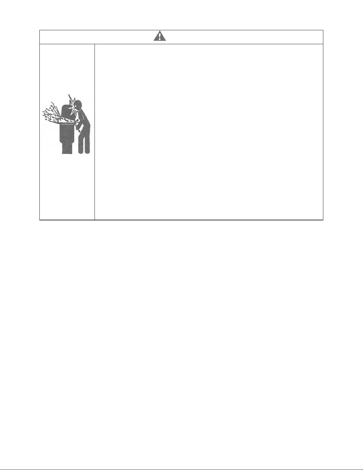
WARNING
THIS FILTER OP E R A T E S UNDER HIGH PRESSURE. WHEN ANY PART OF
THE CIRCULAT I N G SYSTEM (e.g. LOCK RING, PUMP, FILTER VALVES,
ETC.) IS SERVICED, AIR CAN ENTER THE SYSTEM AND BECOME
PRESSURIZED. PRESSURIZED AIR CAN CAUSE THE LID TO BE BLOWN
OFF WHICH CAN RESULT IN SEVERE INJURY, DEATH, OR PROPERTY
DAMAGE. TO AVOID THIS POTENTIAL HAZARD, FOLLOW THESE
INSTRUCTIONS.
1. BEFORE REPOSITIONING VALVES AND BEFORE BEGINNING THE
ASSEMBLY, DISASSEMBLY, OR ADJUSTMENT OF THE LOCK RING OR
ANY OTHER SERVICE OF THE CIRCULATING SYSTEM: (A) TURN THE
PUMP OFF AND SHUT OFF ANY AUTOMATIC CONTROLS TO ENSURE
THE SYSTEM IS NOT INADVERTANTLY STARTED DURING THE
SERVICING; (B) OPEN AIR RELI EF VALVE; (C) WAIT UNTIL ALL
PRESSURE IS RELIEVED.
2. WHENEVER INSTALLING THE FILTER LOCK RING FOLLOW THE
CLEANING FILTER INSTRUCTIONS EXACTLY.
3. ONCE SERVICE OF THE CIRCULATING SYSTEM IS COMPLETE
FOLLOW THE INITIAL START SYSTEM RESTART INSTRUCTIONS
EXACTLY.
4. MAINTAIN CIRCULATION SYSTEM PROPERLY. REPLACE WORN OR
DAMAGED P ARTS IMMEDIATELY (e.g., lock ring, pressure gauge, relief
valve, o-rings, etc).
5.
BE SURE THAT THE FILTER IS PROPERLY MOUNTED AND
POSITIONED ACCORDING TO THE INSTRUCTIONS PROVIDED.
SECTION II. HOW YOUR FILTER WORKS
Your Diatomaceous Earth (D.E.) filter is designed to produce clear, sparkling water and
operate for years with a minimum of maintenance w h e n installed, operated and maintained in
accordance with these instructions.
A. YOUR FILTER USES ELEMENT GRIDS WITH D.E. TO REMOVE DIRT PARTICLES
FROM THE WATER.
1. Dirt is collected in the filter by t h e element grids as water flows through the filter. Water
enters the filter through the filter inlet port and is distr i b u t e d evenly through the element
grids.
2. The dirt is removed by the D.E. coating on the fabric and the clean water flow s through th e
filter outlet port and is returned to the pool through the piping or hoses.
B. AFTER A PERIOD OF TIME, DIRT WILL ACCU M U L A TE IN THE FILTER CAUSING A
RESISTANCE TO THE FLOW OF WATER THROUGH THE FILTER.
1. This resistance results in a d iminished flow of water and a r ise in the filter pressure.
Eventually the filter will have removed so much dirt and the filter pressure risen to such a
point that it will be necessary to clean your filter, see SECTION V. CLEANING THE
FILTER.
2. The filter’s function is to remove suspended matter from the water and does not sanitize the
water. For sparkling clear water, the water must be sa nitized as well as balanced.
3. Pool chemistry is a specialized area, and you should consu l t your loca l pool serv i c e
specialist for specific details. In general, proper pool sanitation requires a f r e e chlorine
level of 1 to 2 PPM and a PH range of 7.2 to 7.6.
Rev. F 6/15/06
3 P/N 99101200
Page 4

READ AND FOLLOW ALL SAFETY INSTRUCTIONS
WARNING
F
ailure to operate your filter system or inadequate filtration can cause poor water clarity obstructing
visibility in your pool. Pool water clarity may obscure objects in the water, which while swimming and
diving could cause severe personal injury and death. Never swim in a pool with poor water clarity.
SECTION III. INSTALLATION
To install this filter s y s t e m , you will need the following simple tools – a screwdriver, pliers,
and ½” wr e n c h.
1. Carefully remove the equipment from the carton and check for any evidence of damage due
to rough handling or sh i p p i ng . If any of the equipment is damaged, immediately notify the
organization where the equipment was purchased.
2. This filter should be mounted on a lev e l concrete sla b , preferable concrete poured in a form
or on a platform constru c t e d of concre t e block or brick.
3. Position the filter tank on the mounting base so that the drain plug is oriented away from
the motor moun t side of the base . Secure the tank to the base with two (2) 5/16-18 bolts.
4A. For Dynamo Pumps:
Place the pump on th e base with the lint pot to the same side as the
Inlet port of the ta nk. Secure the pump to the base with two (2) 5/16-18 bolts. See
Diagram 2.
4B. For OptiFlo Pumps:
Place the pump on the base with the lint pot to the same side as the
Outlet port of the ta nk. Secure the pump to the base with two (2) 5/16-18 bolts. See
Diagram 3.
5. Do not mount electrical controls (on/off sw i t c h e s , timer, etc) over the filter. You need to be
able to stand clear of the filter when starting the pump.
6. Install the conne c t o r hose, Ite m 19 on page 13, to the inlet port of the t ank, tightening the
union nut that is a ttached to th e tank, only hand tight. Bend the hose 90 degrees to fit the
threaded union nut over the outlet po r t of the pump. Hand tighten only.
7. Insert the check va lve into the outlet port of the filter,
making sure the rubber diaphragm is facing outward,
see Diagram 1.
8. Install the union elbow adaptor to the outlet port of
the tank tightening the nut only hand tight. Secure
the flex hose with a hose cl a mp. Tighten the clamp
with a screwdriver. Connect the f l ex hose from the
outlet side of the fi l ter to the return fitting on the pool
wall, using a hose cla mp.
9. Screw the hose adaptor, item number 711006 on page
13, into the inlet p ort of the pump. This is the
opening in th e sidewall of the pump pot. Use Teflon
tape on the threads and tighten no more than one (1) turn past hand tight. Connect the flex
hose to this adaptor with a hose clamp and tighten with a screwdriver. Connect the hose
from the inlet port of the pump to the skimmer, using a hose clamp.
Rev. F 6/15/06
4 P/N 99101200
Page 5
READ AND FOLLOW ALL SAFETY INSTRUCTIONS
10. Install the High Flow air relief valve to the top of the tank lid. See Diagrams 2 and 3,
Detail A. This is an O-ring seal that requires hand tightening only.
11. Install the pressure gauge in the ¼”NPT threaded hole in the tank lid, using Teflon tape on
the threads. See Di agrams 2 and 3, Detai l B.
12. Never install a pump in this sys tem that exceeds the maximum pressure of the filter. See
data label.
13. If using th e optional
Chlorinator Base, knockout the two slots o n the system base with a
hammer and screwdriver.
14. Slide the two tabs on the Chlorinator Base into the slots on the system base.
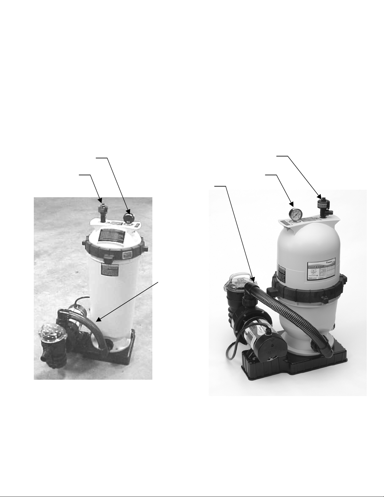
Detail B
Detail A
Detail A
Detail B
Connector
Hose Assy
170046
Connector
Hose Assy
175015
Diagram 2 Diagram 3
(Installation of Dynamo Pump shown) (Installation of O p tiFlo Pump Shown)
Rev. F 6/15/06
5 P/N 99101200
Page 6
READ AND FOLLOW ALL SAFETY INSTRUCTIONS
SECTION IV.
INITIAL ST A R T UP AND RESTART I N S T RUC T IO N S.
1. Be sure all connections have been made and are secure.
2. Make sure the hair and lint pot of the pump is filled with water. (FAILURE TO FILL THE
HAIR AND LINT POT WITH WATER WILL RESULT IN DAMAGE TO THE PUMP
AND PUMP SEAL).
3. OPEN THE HIGH FLOW
TM
MANUAL AIR RELIEF VALVE UNTIL IT SNAPS INTO
THE FULL OPEN POSITION (THIS ONLY REQUIRES A ¼ TURN COUNTERCLOCKWISE).
4. STAND CLEAR OF THE FILTER. Start pump allowing the filter tank to fill with water.
Close the High Flow
TM
manual air relief valve after a steady stream of water appear s.
5. COA T I NG THE FILTER ELEMENTS WITH DIATOMACEOUS EARTH. With the
pump on, i n troduce the recommended amount of D.E. through the skimmer (see chart
below), this will pre-coat the element grid s. A 1 lb. coffee can is equal to ½ l b of D.E.; see
Chart 1.
DIATOMACEOUS EARTH, CHART 1
Model Rated No. of 1 lbs. Weight of
No. GPM Coffee Cans Diatomite
56344xxx 44 3 1.5 lbs
56366xxx 66 4 2 lbs
CAUTION
Do not operate filter for more than two minutes without a pre-coat of D.E. on the grids.
6. Your filter has now started its filter cycle. You should check that the water is returning to
the pool and take no t e of the operating press ur e .
My original starting pressure is ________PSI with the filter clean.
7. Check the system for water l e aks. If a leak is found, shut off pump before correcting the
leak.
8. As the filter removes dirt and impurities from the pool water, the accumulation will cause
the filter p ressure to ri se and the flow to diminish. When the pressure gauge reading is 8 to
10 PSI h i g h e r than the clean filt e r reading n o ted above, it is time to clean the filter’s
element grids, see SECTION V. CLEANING THE FILTER.
Rev. F 6/15/06
6 P/N 99101200
Page 7

READ AND FOLLOW ALL SAFETY INSTRUCTIONS
WARNING
THIS FILTER OPERATES UNDER HIGH PRESSURE. WHEN ANY PART OF THE
CIRCULATING SYSTEM (e.g. LOCK RING, PUMP, FILTER, VALVES, ETC.) IS
SERVICED, AIR CAN ENTER THE SYSTEM AND BECOME PRESSURIZED.
PRESSURIZED AIR CAN CAUSE THE LID TO BE BLOWN OFF WHICH CAN RESULT
IN SEVERE INJURY, DEATH, OR PROPERTY DAMAGE.
SECTION V. CLEANING THE FILTER
1. Cleaning frequency will vary from pool to pool and with other factors such as weather
conditions, heavy rains, dust pollen, bather load and water chemistry.
a. Check the pressure gauge reading on a regular basis and when the pressure gauge
reading increases 8 to 10 PSI over the initial clean filter reading, it is time to clean
your ELEMENT GRIDS.
2. Turn the pump off, shut off any aut o matic controls to assure that the system is not
inadvertently started during servicing.
3. Plug the skimmer port with a rag. This w i l l prevent pool water from running out during
servicing.
4. Open the High Flow
TM
manual air re l i e f valve, a n d the filte r drain plug.
5. Remove the hair and lint s trainer pot lid and cle an the bas k e t . Replace the basket and
secure the li d .
6. Remove the filter lock ring by depressing the two (2) spring loaded locking blocks and
rotating the ring counter-clockwise until the ring is free from the filter body.
7. Remove the filter lid using the lifting han dles on the lid.
8. Remove the ELEMENT GRID assembly from the filter body by using the lifting handles
and pulling straight up.
9. Using a garden hose, direct water spray at the EL EMENT GRID to dislodge and wash
away any accumulated foreign matter and Diatomaceous Earth. Thoroughly c l e a n the
elements.
CAUTION
Do not operate filter for more than two m i n u t e s without a pre-coat of D.E. on the grids.
10. Clean and remove d e b r i s from the inside of the filter tank.
11. Replace the ELEMENT GRID ASSEMBLY into the filter tank body making sure the
arrow on the top of the center core is aligned with the filter inlet port. You w ill be able to
feel the assemble drop i nto and lock into place when in the proper position.
Rev. F 6/15/06
7 P/N 99101200
Page 8

READ AND FOLLOW ALL SAFETY INSTRUCTIONS
12. Clean any debris from the O-ri ng at the top of the filter tank. Apply a silicone lubricant to
the O-ring.
DO NOT US E A PETROLEUM-B A SE LUBRICANT ON THE O-RING.
Failure to properly clean and lubricate the O-ring may result in water leakage.
13. Replace the filter tank lid making sure it is fully and firmly seated on the tank body.
14. Place the filter lock ring over the fi lter lid, and turn cloc k w ise until t he safety latches click
and the lo c k ring hits the stops on the body.
DO NOT ATT EM P T TO OVER TIGHTEN THE FILTER LOCK RING AFTER THE
SAFETY LATCHES HAVE ENGAGED.
WARNING
If the filter lock ring is damaged, replace it immediately. This filter operates
under high pressure. Replace locking ring if damaged or worn. Failure to
replace locking ring can res ult in the lid separating from the filter, which can
cause severe injury or death.
15. Replace the drain cap hand tight only.
16. Follow Initial Start Up and System Restart Instructions; see Section IV.
WARNING
Failure to operate your filter system or inadequate filtration can cause poor water clarity obstructing
visibility in your pool. Pool water clarity may obscure objects in the water, which while swimming and
diving could cause severe personal injury and death. Never swim in a pool with poor water clarity.
Rev. F 6/15/06
8 P/N 99101200
Page 9

READ AND FOLLOW ALL SAFETY INSTRUCTIONS
SECTION VI.
CHECK VA LVE INSTALLATION INSTRUCTIONS
WARNING
THIS FILTER OP E R A T E S UNDER HIGH PRESSURE. WHEN ANY PART OF
THE CIRCULAT I N G SYSTEM (e.g. LOCK RING, PUMP, FILTER VALVES,
ETC.) IS SERVICED, AIR CAN ENTER THE SYSTEM AND BECOME
PRESSURIZED. PRESSURIZED AIR CAN CAUSE THE LID TO BE BLOWN
OFF WHICH CAN RESULT IN SEVERE INJURY, DEATH, OR PROPERTY
DAMAGE. TO AVOID THIS POTENTIAL HAZARD, FOLLOW THESE
INSTRUCTIONS.
15. BEFORE REPOSITIONING VALVES AND BEFORE BEGINNING THE
ASSEMBLY, DISASSEMBLY, OR ADJUSTMENT OF THE LOCK RING OR
ANY OTHER SERVICE OF THE CIRCULATING SYSTEM: (A) TURN THE
PUMP OFF AND SHUT OFF ANY AUTOMATIC CONTROLS TO ENSURE
THE SYSTEM IS NOT INADVERTANTLY STARTED DURING THE
SERVICING; (B) OPEN AIR RELI EF VALVE; (C) WAIT UNTIL ALL
PRESSURE IS RELIEVED.
16. WHENEVER INSTALLING THE FILTER LOCK RING FOLLOW THE
CLEANING FILTER INSTRUCTIONS EXACTLY.
17. ONCE SERVICE OF THE CIRCULATING SYSTEM IS COMPLETE
FOLLOW THE INITIAL START SYSTEM RESTART INSTRUCTIONS
EXACTLY.
18. MAINTAIN CIRCULATION SYSTEM PROPERLY. REPLACE WORN OR
DAMAGED PAR TS IMMEDIATELY (e.g., lock ring, pressure gauge, relief
valve, o-rings, etc).
19.
BE SURE THAT THE FILTER IS PROPERLY MOUNTED AND
POSITIONED ACCORDING TO THE INSTRUCTIONS PROVIDED.
1. T u r n the pump off, shut off any automatic controls to assure that the system is not
inadvertently started during servicing.
2. Open the High Flow
TM
manual relief valve.
3. Plug the suction line by inserting a rag into th e skimmer port, or if equipped with a valve
close it at this time to prevent water from siphoning from the pool during servicing.
4. If possible, plug the return line to prevent siphoning. If this cannot be done, disconnect the
union fitting from the o utlet port of the fil ter and quickly place the return hose into the
pool.
5. Re move the drai n cap to empty the water from the filter.
6. Insert the Check Valve into the outlet port approximately
¾” to 1” deep making sure the rubber diaphragm is
facing outward (toward you), see Diagram 1.
7. Reconnect the return hose to the outlet port and t i g h t e n
the union fitting.
8. Replace the drain cap.
9. Remove the rag from the ski m mer or open the valve on
the suction line.
10. If the return line was plugged, unplug it at this time.
Rev. F 6/15/06
9 P/N 99101200
Page 10

READ AND FOLLOW ALL SAFETY INSTRUCTIONS
11. With the High FlowTMmanual air r e l i ef valve in the op e n position, start the pump, after a
steady stream of water appears close the High Flow
TM
manual air relief valve.
12. Your system is now in operatin g order.
SECTION VII. WINTERIZING THE FILTER
1. In areas that have freezing temperatures, the pool equipment must be winterized to protect
it from damage.
2. With the equipment tu r n e d off, op en the High Flow
TM
manual air relief valve.
3. Remove the drain port cap, and allow the filter t o drain completely.
4. Remove the drain port plugs on the pump and allo w the pump to drain completely.
5. Drain all appropriate system piping.
6. It is recommended that the pump and filter be c over ed with a tarpaulin or plastic sheet to
inhabit deterioration from the weather.
DO NOT WRAP THE P U MP MOTOR IN PLASTIC.
7. Your filter is now winterized.
8. S e e SECTION IV. INITIAL START-UP AND SYSTEM RESTART, when pool is ready
to be ope n ed for the season.
SECTION VIII.
CLEANING THE HIGH FLOW
TM
MANUAL AIR RELIEF
VALVE
1. Turn the pump off and sh u t off any automatic controls to
ensure that the system is not inadve r t e ntly started during
servicing.
2. OPEN THE HIGH FLOW
TM
MANUAL AIR RELIEF
VALVE UNTIL IT SNAPS I N T O THE FULL OPEN
POSITION, THEN WAIT UNTIL ALL PRESSURE IS
RELIEVED.
3. With the relief valve attached to the fil ter tank, pull out the
locking tabs and remove th e valve stem and cover assembly
with a co u n te r clockwise a nd lifting motion, see Figure 4.
4. Clean the debris from the valve stem and body. Verify that
the filter tank’s air passage is o p e n e d by inserting a 5/16”
drill bit through the valve body. Verify tha t the O-rings are
in good condition, properly positioned, and lubricated with
a silicone base lubricant.
5. Reinstall the valve stem and cover assembly with a
downward and clockwise motion until it snaps into
position.
Rev. F 6/15/06
10 P/N 99101200
Page 11

READ AND FOLLOW ALL SAFETY INSTRUCTIONS
SECTION IX. TROUBLE SHOOTING
PROBLEM CAUSE REMEDY
Pool water not
s
ufficiently clean.
1. Pool chemistry not adequate to inhabit algae growth.
2
. Inade quate turnover rate.
Maintain pool chemistr y or consult pool service technician.
R
un system for longer time or consult dealer or pool
service tech nician.
Higher filter pressure. 1. Insufficient cleaning of the filter element.
2. Partial closed valve or restriction.
Clean the filter element (see Cleaning Filter instructions).
O
pen valve or remove obstruction in return line.
Short filter cycles. 1. Insufficient cleaning of filter element.
2. Pool chemistry not adequate to inhabit algae growth.
3. Flow rate too high.
Clean the filter element (see Cleaning Filter instructions).
Maintain pool chemistry or consult pool service technician.
Restrict flow to capacity of filter.
Return flow to pool
diminished, low filter
pressure.
1. O bstruction in the pump hair and lint pot.
2. Obstruction in pump.
3. O bstruction in suction line to pump.
Clean basket in strainer.
Disassemble and clean pump.
Clean skimmer basket. Remove obstruction in lines.
Open valves in suction line.
SECTION X. PUMP INSTRUCTIONS
WARNING
To reduce the risk of electrical shock, only connect to a GFCI protected receptacle.
Failure to do so could result in an electrical shock to pool users, installers, or others,
which can result in serious personal injury or death.
1. T O PRIME PU M P – (pump must be off).
a. Unscrew the lid from the pot and fill the pot with water to level of suction line.
Inspect O-ring, lubricate with silicone lubricant.
b.
Dynamo Pump:
Screw the lid into the pot, hand tighten, lid shoulder wi l l come to
rest on the pot surf ace.
OptiFlo Pump:
Replace the lid on t h e pot. Align the clamp ears with the slots on the
strainer pot. Press th e lid and clamp down and twist the clamp clockwise to engage.
c. Turn the pump on; priming time will vary depending up o n elevation above water
level and horizontal distance of suction line.
d. If the filter is installed, open the High Flow
TM
manual air relief valve, (before turning
the pump on) until a steady stream of water comes out, then close the High Flow
TM
manual air relief valve.
e. The pump is now primed. If the pump is installed below water level, close the return
line prior to filling the hair and lint pot with water. Line must be reopened before
turning the p ump on.
Rev. F 6/15/06
11 P/N 99101200
Page 12

READ AND FOLLOW ALL SAFETY INSTRUCTIONS
2. TO CLEAN THE BASKET – (pump must be off)
a. Follow the instructions above to prime the pump.
b. After removing the lid, remove the basket and empty the debris.
c. Replace the basket and proceed to fill the pot wi t h water.
d. It is important to visually in s p e c t the basket , through th e see through lid, at least once
a week. A dirty basket will reduce the efficiency of your system, and can put an
abnormal load on the pu m p , which could result in costly repai r bills.
3. SHAFT SEAL – (rotary seal). The shaft seal consists of two (2) parts:
a. Rotating spring loaded seal, press fitted into t he impeller.
b. A stationary ceramic seal, press fitted into the rear of the volute.
4. THE ELECTRIC MOTOR.
a. The electric motor should be pro t e c t e d from foreign matter, water splashing, hos i n g ,
and the w e a t h e r . Enclosures should be well ventil a t e d to prevent overheating. If a
motor becomes wet, permit it to dry before running it. If a motor has been damaged
by water o r dirt, the warranty is void.
b. The motors used on these pu mps are 48 frame through bolt motors. The through bolts
are used to secure the volute t o the motor. When replacing the motor, mark the end
bells and the motor shell to ind ica te alignment. Remove the four nuts from the
through bolts at the sh a f t end. Place the shaft through the back of the volute and
locate the bolts in l ine with the brass inserts located in the four (4) legs at the rear of
the volute. Be sur e the end bell and the shell marking line up. Securely fasten th e
motor to the volute.
c. Protect the motor from heat. Provide ample ventilation.
CAUTION
The highly polished and lapped faces of the seal are easily damaged. Handle with care.
This centrifugal pump requires little or no service, however the shaft seal will wear with normal use over
the years and will require periodic replacement.
CAUTION
DO NOT R UN PUMP DRY. If the pump is run dry, the mechanical seal will be damaged and external
leakage will occur. When the seal is damaged, the seal must be replaced.
CAUTION
Always maintain proper w a t e r level in the pool. Water level must be half way up the skimmer opening.
A low water level can cause the pump motor to run dry which will damage the mechanical seal and
cause external leakage.
Rev. F 6/15/06
12 P/N 99101200
Page 13

READ AND FOLLOW ALL SAFETY INSTRUCTIONS
SECTION XI. TECHNICAL DATA
A. FILTER AND BASE – REPLACEMENT PARTS
Warrior D.E. Filter Replacement Parts
Item Part Number Description Quantity
1 98209800 High FlowTMManual Relief Valve 1
2 53003201 Pressure Gauge 1
3 59053200 Lid, 44 GPM Filter, Black 1
3 190041 Lid, 44 GPM Filter, Almond 1
3 59025600 Lid, 66 GPM Filter, Black 1
3 190042 Lid, 66 GPM Filter, Almond 1
4 59052901 Locking Ring Assy 1
5 87300400 Body O-Ring 1
6 39302700 Tie Rod Knob 1
7 59016200 Air Bleed Sock Kit 1
8 59022501 Tie Rod/Manifold Assy., 44 GPM Filter 1
8 59022502 Tie Rod/Manifold Assy., 66 GPM Filter 1
9 59011200 Air Bleed Tube, 44 GPM Filter 1
9 59011300 Air Bleed Tube, 66 GPM Filter 1
10 59023000 Top Grid Support 1
11 59009600 Large Grid Assy, 44 GPM Filter 4
11 59009700 Large Grid Assy, 66 GPM Filter 4
12 59005200 Small Grid Assy, 44 GPM Filter 2
12 59005300 Small Grid Assy, 66 GPM Filter 2
13 59055600 Bottom, 44 GPM Filter, Black 1
13 178562 Bottom, 44 GPM Filter, Almond 1
13 59055700 Bottom, 66 GPM Filter, Black 1
13 178563 Bottom, 66 GPM Filter, Almond 1
14 86202000 Drain Cap Assy 1
15 51005000 Drain Cap Gasket 1
16 39104500 Union Nut “C” Clip 2
17 98212200 Union Nut 2
18 39102800 Union Nut O-Ring 2
19 175015 Connector Hose Assy With O-Ring 1
(Dynamo Pump)
19 170046 Connector Hose Assy With O-Ring 1
(OptiFlo Pump)
20 39107400 Outlet Connector 1
21 51516100 Check Valve Kit 1
22 178540 Base Assy 1
23 178541 Chlorinator Base 1
24 Pump 1
25 59005800 Grid Pack Assy, 44 GPM 1
25 59005900 Grid Pack Assy, 66 GPM 1
26 79304700 Union, Body for Chlorinator Attachment 1
98219800 Bolt, Motor To Stand 2
354265 Bolt, Filter To Stand 2
39201400 Pump Support 2
In Units P u r c ha se d With a Hose Kit (Not Shown)
27 711006 Adaptor, 1 ½” Hose 1
28 711004 Clamp, Hose 4
29 155005 Kit, Flex Hose 12 Ft 2
30 155151 Kit, Flex Hose 6 Ft 2
Rev. F 6/15/06
13 P/N 99101200
Page 14

READ AND FOLLOW ALL SAFETY INSTRUCTIONS
B.
Dynamo
PUMP REPLACEMENT PARTS
Item Part Number Description Quantity
1 356597 Motor, 1HP SPL, 1 Phas e , 60 Hz, 115V 1
1 356595 Motor, 1 1/2HP SPL, 1 Phase, 60Hz , 115V 1
1 356469 Motor, 2HP SPL, 1 Phas e , 60Hz, 115V 1
2 354632 Bracket, Diffuser, 3/4HP 1
2 354633 Bracket, Diffuser, 1HP, 1 1/2HP 1
3 354542 Square Nut No. 10-24 Sta i n l e s s Steel 6
4 354634 O-Ring, 3/16” Pump Bracket 1
5 354545 Seal – Me c h a n ic a l , 5/8” 1
6 354552 Impeller Assembly, 1H P SPL 1
6 355122 Impeller Assembly, 1 1/2HP SPL, 2HP SPL 1
7 354630 Housing Body 1
8 354541 Screw – Slotted Hex No. 10-24 x 1 ½” 6
9 154481 Plug, ¼” 2
10 237062 O-Ring 1
11 354530 Pot 1
12 354548 Basket Assembly 1
13 354533 O-Ring, Lid 1
14 354531 Lid 1
15 79137700 Cord Assembly, 3’ Standard Plug 1
15 155137 Cord Assembly, 3’ Twist Lo c k Plug 1
Rev. F 6/15/06
14 P/N 99101200
Page 15

READ AND FOLLOW ALL SAFETY INSTRUCTIONS
C.
OptiFlo
PUMP REPLACEMENT PARTS
Item Part Number Description Quantity
1 154699 Drain Plug 3
2 354545 Mechanical Seal 1
3 354552 Impeller 3/4HP, 1HP SPL 1
3 350017 Impeller 1 1/2HP SPL 1
4 192115 O-Ring, Drain Plug 3
5 357213 Volute 1
6 357255 O-Ring @-357 2
7 357227 Lid 1
8 357228 Pot 1
9 357239 Clamp, Cam & Ramp 1
10 357254 Square Nut, ¼-20 Stainless Steel 4
11 355667 Basket 1
12 357215 Seal Plate 1
13 350103 O-Ring 1
14 98209000 Screw-Phillips Pan Head ¼-20 x 1 ½” 4
15 356597 Motor With Switch, 3/4HP 1HP SPL, 115V 1 S p e e d 1
15 356595 Motor With Switch, 1 1 / 2 H P SPL, 1 1 5 V , 1 Speed 1
15 356551 Motor With Switch, 1 HP 1 1/2HP SPL, 115V, 2 Speed 1
16 79137800 Cord Assembly, 3’ Long With Standard Plug 1
16 155137 Cord Assembly, 3’ Long With Twist Lock Plug 1
17 350444 Motor Switch, On/Off 1
17 356546 Motor Switch, Hi/Lo/Off 1
Rev. F 6/15/06
15 P/N 99101200
Page 16

READ AND FOLLOW ALL SAFETY INSTRUCTIONS
D. CSA ENCLOSURE REPLACEMENT PARTS
Item Part Number Descri p tio n Quantity
1 354621 Body, Motor Enclosure 1
2 354881 Cap, Motor Enclosure 1
3 154716 Screw, No 10 Self Tapping 3
4 155371 Cord Assy, 25’ Long With Standard Plug and 1
Plastic Bushing (P/N41412700)
5 155187 Switch, On/Off Toggle (CSA) 1
6 155193 Wire, 6” Jumper 1
7 350024 Locknut, Steel 1
8 153263 Base, CSA 1
9 354265 Screw, 5/16-18 x ¾”, Hex Head w/Washer, Stainless Steel 4
10 357284 Enclosure Ring 1
2
7
6
9
10
1
4
3
5
MOTOR BOLTS (4)
8
Rev. F 6/15/06
16 P/N 99101200
Page 17

NOTES
Rev. F 6/15/06
17 P/N 99101200
Page 18

NOTES
Rev. F 6/15/06
18 P/N 99101200
Page 19

READ AND FOLLOW ALL SAFETY INSTRUCTIONS
This page is blank.
Pentair Pool Products, Inc.
1620 Hawkins Ave., Sanford, NC 27330 x (919) 774-4151
10951 West Los Angeles Ave., Moorpark, CA 93021 x (805) 523-2400
Rev. F 6/15/06
19 P/N 99101200
Page 20

READ AND FOLLOW ALL SAFETY INSTRUCTIONS
SAVE THESE INSTRUCTIONS
Pentair Pool Products, Inc.
1620 Hawkins Ave., Sanford, NC 27330 x (919) 774-4151
10951 West Los Angeles Ave., Moorpark, CA 93021 x (805) 523-2400
Rev. F 6/15/06
20 P/N 99101200
 Loading...