

Page 1
MODEL D65-20AVD
INDUSTRIAL PUMPS
INSTRUCTIONS AND SERVICE MANUAL
NOTE! To the installer: Please make sure you provide this manual to the owner of the equip ment or to the responsible
party who maintains the system.
Part # 13800A917 | © 2012 Pentair Ltd. | 12/05/12
Page 2
SPECIFICATIONS
BELT DRIVE SEWER CLEANERS
Type Triplex - Single Acting
*Rated Capacity
Gear Reduction Ratio
*Discharge Capacity
Rated Pressure
Temperature Rating
Cylinder Bore & Stroke
Suction Size
Discharge Size
Cylinder Body Mtl.
Cylinder Mtl.
Piston Packing Mtl.
Piston Assembly Mtls.
Valve Mtl.
Valve Seat Mtl.
Pump Drive End
Pinion Shaft Speed
at Rated Capacity
Pinion Shaft Exten. Dia.
Keyway
Pinion and Crankshaft
Main Bearings
Crankshaft Journ. Bearings
Crosshead Pin Bearing
Recommended Regulator
Cylinder Removal Tool Kit
Valve Seat Removal Tool Kit
Allen Wrench for
Packing Capscrew
*Based on 100% Volumetric Efficiency – Allow 5 to 7% for Valve Slippage.
69.7 GPM @ 456
Strokes/Minute*
3.95
3.87 GPM per 100
Pinion RPM*
2000 PSI Max.
160°F Max.
2" x 3-3/4"
3" NPT
1-1/4" NPT
Ductile Iron
Ceramic
Coated Stainless Steel
Molded Composition
V-Rings
Stainless Steel
Delrin
Stainless Steel, Hardened
Helical Gear Single
Reduction
1800 RPM Max.
1-5/8"
3/8" x 3/16" Straight
Tapered Roller
Steel/Babbit Inserts
Bronze Bushing
15696C5
17539B1
19555B
8574A11
GENERAL INSTRUCTIONS
CAUTION: Positive Displacement Pumps must have a
proper size and operable type of pressure regulating
valve or pressure relief valve piped into the discharge
line. This is mandatory to prevent damage to pump
and piping or possible injury to personnel. Do not
install any valves or shutoff devices in the by-pass
line from pressure regulator to tank or supply.
CAUTION: All pumps should be installed level.
For mobile applications the maximum angle of
intermittent operation should be no more than
5 degrees in any one direction.
CALIFORNIA PROPOSITION 65 WARNING:
This product and related accessories
contain chemicals known to the State of California
to cause cancer, birth defects or other reproductive
harm.
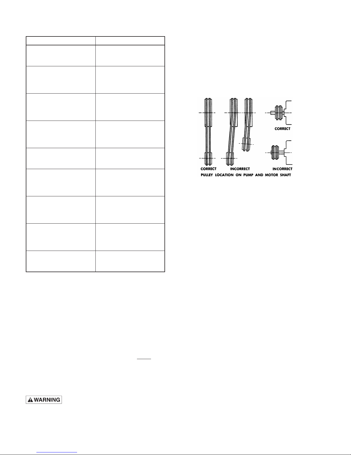
With belt drives, pulley on both engine and pump should
be located as closely as possible to bearing to reduce
bearing and shaft bending loads.
NOTE: See Maintenance Chart for Belt Tension
Specifications in Sewer Cleaner “Operator’s Manual”.
Make sure that all bolts, nuts, set screws, and keys are
properly tightened.
STARTING PUMP
A. Before starting:
1. Read all instructions carefully.
2. Fill pump crankcase with recommended oil to level
mark on oil saber. Oil recommendations are covered
in lubrication section of pump instructions.
3. Replace all drain plugs in pump and piping.
4. Inspect tank to be sure that no foreign material is in
tank or suction line.
5. Fill tank at least half full or connect suction to
water supply. Open valve (if present) in suction line.
Avoid prolonged dry operation which may cause
excessive wear on cylinders and piston packing.
Be sure that an operating pressure gauge is
located in discharge line.
6. Make sure all valves,including spray gun or nozzles,
are open in discharge line. Spray gun may be
anchored to discharge back into tank.
7. Completely back off pressure adjusting screw on
pressure regulating valve.
B. Starting the Unit:
1. After starting, close discharge valve or spray gun
slowly while watching pressure gauge to make sure
relief valve or unloader is operating properly.
2. Adjust relief valve or unloader to desired pressure.
See regulator instructions.
3. Cycle nozzles or gun on and off to be sure that
pressure adjustment and regulator operation is
satisfactory.
NOTE: Nozzle capacity should not exceed 90% of pump
capacity for satisfactory regulator operation. AVOID
FREEZING by draining all water from pump and system
in cold weather.
13800A917 12/05/12
2
Page 3
3
13800A917 12/05/12
Page 4
13800A917 12/05/12
4
Page 5

5
13800A917 12/05/12
Page 6

13800A917 12/05/12
6
Page 7

7
13800A917 12/05/12
Page 8

13800A917 12/05/12
8
Page 9

9
13800A917 12/05/12
Page 10

13800A917 12/05/12
10
Page 11

11
13800A917 12/05/12
Page 12

STANDARD LIMITED WARRANTY
CENTRIFUGAL & RECIPROCATING PUMPS
Pentair Myers® warrants its products against defects in material and workmanship for a period of 12 months from
the date of shipment from Pentair Myers or 18 months from the manufacturing date, whichever occurs first – provided
that such products are used in compliance with the requirements of the Pentair Myers catalog and technical manuals.
During the warranty period and subject to the conditions set forth, Pentair Myers, at its discretion, will repair or
replace to the original user, the parts that prove defective in materials and workmanship. Pentair Myers reserves the
right to change or improve its products or any portions thereof without being obligated to provide such a change or
improvement for prior sold and/or shipped units.
Seals, piston cups, packing, plungers, liners and valves used for handling clear, fresh, nonaerated water at a
temperature not exceeding 120ºF are warranted for ninety days from date of shipment. All other applications are
subject to a thirty day warranty. Accessories such as motors, engines and auxiliary equipment are warranted by
the respective manufacturer and are excluded in this standard warranty. Under no circumstance will Pentair Myers
be responsible for the cost of field labor, travel expenses, rented equipment, removal/reinstallation costs or freight
expenses to and from the factory or an authorized Pentair Myers service facility.
This limited warranty will not apply: (a) to defects or malfunctions resulting from failure to properly install, operate
or maintain the unit in accordance with the printed instructions provided; (b) to failures resulting from abuse, accident
or negligence; (c) to normal maintenance services and parts used in connection with such service; (d) to units that
are not installed in accordance with applicable local codes, ordinances and good trade practices; (e) if the unit is
moved from its original installation location; (f) if unit is used for purposes other than for what it is designed and
manufactured; (g) to any unit that has been repaired or altered by anyone other than Pentair Myers or an authorized
Pentair Myers service provider; (h) to any unit that has been repaired using non factory specified/OEM parts.
Warranty Exclusions: PENTAIR MYERS MAKES NO EXPRESS OR IMPLIED WARRANTIES THAT EXTEND BEYOND THE
DESCRIPTION ON THE FACE HEREOF. PENTAIR MYERS SPECIFICALLY DISCLAIMS THE IMPLIED WARRANTIES OF
MERCHANTABILITY AND FITNESS FOR ANY PARTICULAR PURPOSE.
Liability Limitation: IN NO EVENT SHALL PENTAIR MYERS BE LIABLE OR RESPONSIBLE FOR CONSEQUENTIAL,
INCIDENTAL OR SPECIAL DAMAGES RESULTING FROM OR RELATED IN ANY MANNER TO ANY PENTAIR MYERS
PRODUCT OR PARTS THEREOF. PERSONAL INJURY AND/OR PROPERTY DAMAGE MAY RESULT FROM IMPROPER
INSTALLATION. PENTAIR MYERS DISCLAIMS ALL LIABILITY, INCLUDING LIABILITY UNDER THIS WARRANTY, FOR
IMPROPER INSTALLATION. PENTAIR MYERS RECOMMENDS INSTALLATION BY PROFESSIONALS.
Some states do not permit some or all of the above warranty limitations or the exclusion or limitation of incidental or
consequential damages and therefore such limitations may not apply to you. No warranties or representations at any
time made by any representatives of Pentair Myers shall vary or expand the provision hereof.
1101 MYERS PARKWAY
ASHLAND, OHIO, USA 44805
419-289-1144
WWW.FEMYERS.COM
Warranty Rev. 12/13
 Loading...