

Pentair Compli 508/2 M, Compli 108/2 M, Compli 400, Compli 508/2 ME, Compli 520/2 M Instruction Manual
...Page 1

EN Instruction Manual
COMPLI
108/2 ME 108/2 M 120/2 M
300 E
400 E 400
508/2 ME 508/2 M 520/2 M
510/4 BW 515/4 BW 525/4 BW 525/2 BW 535/2 BW
1008/2 ME 1008/2 M 1020/2 M 1010/4 BWE
1010/4 BW 1015/4 BW 1025/4 BW 1025/2 BW 1035/2 BW
1210/4 BW 1215/4 BW 1225/4 BW 1225/2 BW 1235/2 BW
JUNG-PUMPEN.DE B 42951-31-1902
Page 2

ENGLISH
You have purchased a product made by Pentair Jung Pumpen and with it, therefore, also excellent quality and service.
Secure this service by carrying out the installation works
in accordance with the instructions, so that our product
can perform its task to your complete satisfaction. Please
remember that damage caused by incorrect installation or
handling will adversely affect the guarantee. Therefore please adhere to the instructions in this manual!
This appliance can be used by children aged 8 years or over
and by persons with limited physical, sensory or intellectual
capabilities, or with limited experience and knowledge, provided that they are supervised or have been instructed in
the safe use of the appliance and are aware of the dangers
involved. Children must not be allowed to play with the appliance. Cleaning and user maintenance must not be carried
out by children unless they are supervised.
Damage prevention in case of failure
Like any other electrical device, this product may fail due to a
lack of mains voltage or a technical defect.
If damage (including consequential damage) can occur as a result of product failure, the following precautions can be taken
at your discretion:
• Installation of a water level dependent (under circumstanc-
es, mains-independent) alarm system, so that the alarm can
be heard before damage occurs.
• Inspection of the collecting tank/chamber for tightness up
to the top edge before – or at the latest, during – installation
or operation of the product.
• Installation of backow protection for drainage units that
can be damaged by wastewater leakage upon product failure.
• Installation of a further product that can compensate in
case of failure of the other product (e.g. duplex unit).
• Installation of an emergency power generator.
As these precautions serve to prevent or minimise consequential damage upon product failure, they are to be strictly
observed as the manufacturer’s guideline – in line with the
standard DIN EN specications as state of the art – when using
the product (Higher Regional Court Frankfurt/Main, Ref.: 2 U
205/11, 06/15/2012).
SAFETY INSTRUCTIONS
This instruction manual contains essential information that
must be observed during installation, operation and servicing. It is therefore important that the installer and the responsible technician/operator read this instruction manual before
the equipment is installed and put into operation. The manual
must always be available at the location where the pump or the
plant is installed.
Failure to observe the safety instructions can lead to the loss
of all indemnity.
In this instruction manual, safety information is distinctly labelled with particular symbols. Disregarding this information
can be dangerous.
General danger to people
Warning of electrical voltage
NOTICE!
Danger to equipment and operation
Qualication and training of personnel
All personnel involved with the operation, servicing, inspection
and installation of the equipment must be suitably qualied
for this work and must have studied the instruction manual in
depth to ensure that they are suciently conversant with its
contents. The supervision, competence and areas of responsibility of the personnel must be precisely regulated by the operator. If the personnel do not have the necessary skills, they
must be instructed and trained accordingly.
Safety-conscious working
The safety instructions in this instruction manual, the existing
national regulations regarding accident prevention, and any
internal working, operating and safety regulations must be adhered to.
Safety instructions for the operator/user
All legal regulations, local directives and safety regulations
must be adhered to.
The possibility of danger due to electrical energy must be prevented.
Leakages of dangerous (e.g. explosive, toxic, hot) substances
must be discharged such that no danger to people or the environment occurs. Legal regulations must be observed.
Safety instructions for installation,
inspection and maintenance works
As a basic principle, works may only be carried out to the equipment when it is shut down. Pumps or plant that convey harmful
substances must be decontaminated.
All safety and protection components must be re-tted and/or
made operational immediately after the works have been completed. Their effectiveness must be checked before restarting,
taking into account the current regulations and stipulations.
Unauthorised modications, manufacture of
spare parts
The equipment may only be modied or altered in agreement
with the manufacturer. The use of original spare parts and
accessories approved by the manufacturer is important for
safety reasons. The use of other parts can result in liability for
consequential damage being rescinded.
Unauthorised operating methods
The operational safety of the supplied equipment is only guaranteed if the equipment is used for its intended purpose. The
limiting values given in the "Technical Data" section may not be
exceeded under any circumstances.
Instructions regarding accident prevention
Before commencing servicing or maintenance works, cordon
off the working area and check that the lifting gear is in perfect
condition.
Never work alone. Always wear a hard hat, safety glasses and
safety shoes and, if necessary, a suitable safety belt.
Before carrying out welding works or using electrical devices,
check to ensure there is no danger of explosion.
People working in wastewater systems must be vaccinated
against the pathogens that may be found there. For the sake of
your health, be sure to pay meticulous attention to cleanliness
wherever you are working.
Make sure that there are no toxic gases in the working area.
Observe the health and safety at work regulations and make
2
Page 3

sure that a rst-aid kit is to hand.
ENGLISH
In some cases, the pump and the pumping medium may be hot
and could cause burns.
For installations in areas subject to explosion hazards, special
regulations apply!
AREAS OF APPLICATION
The ready to connect compli sewage lifting stations are LGA
certied and are suitable for the disposal of wastewater from
toilets and urinals, and domestic wastewater containing the
usual impurities.
The tanks can withstand submersion to a depth of not more
than 2 m of water and a submersion period of up to 7 days.
The control unit cannot withstand submersion, but is splashproof in accordance with IP 44.
If installed in compliance with the regulations and used properly, then this control unit meets the protective requirements
of the EMC Directive 2014/30/EU and is suitable for domestic
use and connection to a power supply from the grid. When
connected to an industrial mains within an industrial operation
with power supply provided by a company-own high-voltage
transformer, insucient immunity to interference has to be
expected.
When using the pumps, the relevant national laws, regulations
and stipulations must be adhered to, for example:
• Sewage disposal units for building and ground drainage
systems (e.g. EN 12050 and 12056 in Europe)
• Installation of low voltage systems (e.g. VDE 0100 in Ger-
many)
• Safety and working materials (e.g., BetrSichV and BGR 500
in Germany)
• Safety in wastewater systems (e.g., GUV-VC5, GUV-R104
and GUV-R126 in Germany)
• Electrical systems and operating resources (e.g., GUV-VA3
in Germany)
• Explosion protection EN 60079-0,
EN 60079-1, EN 60079-14, EN 60079-17 and EN 1127-1
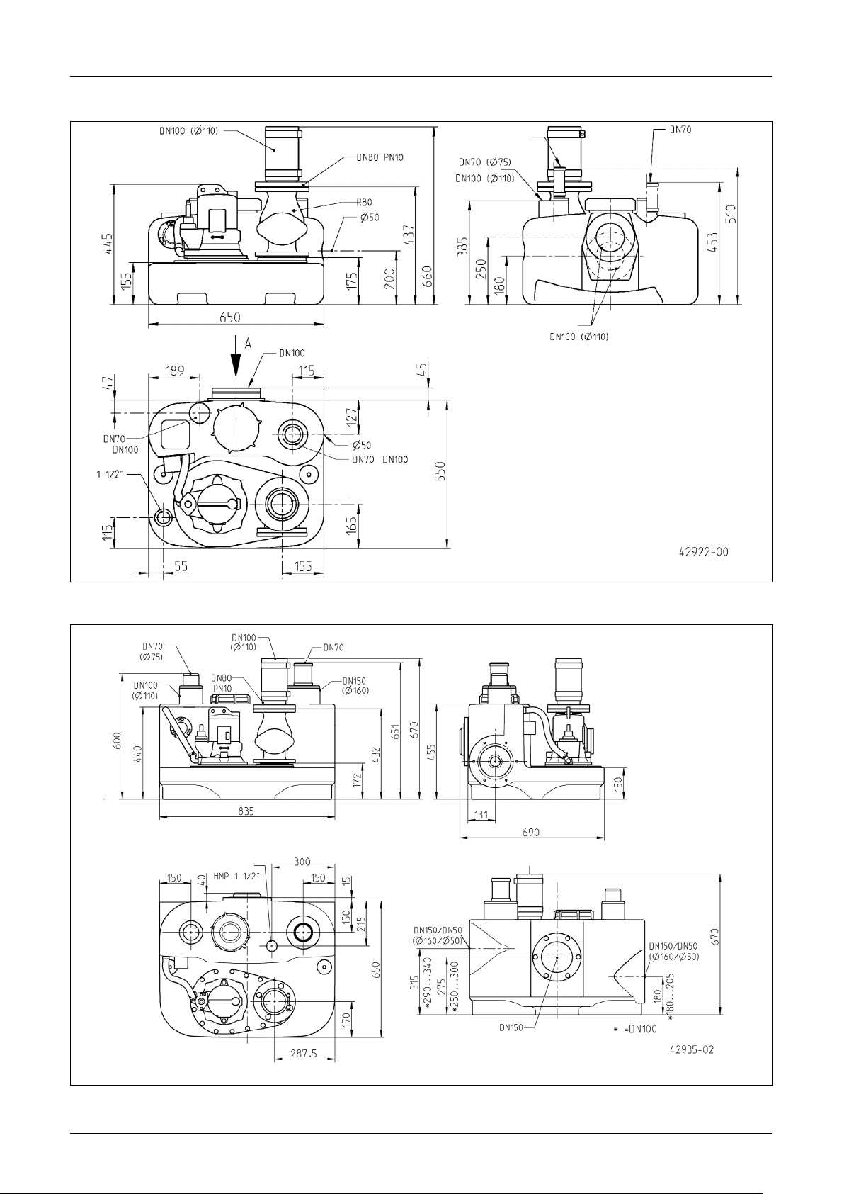
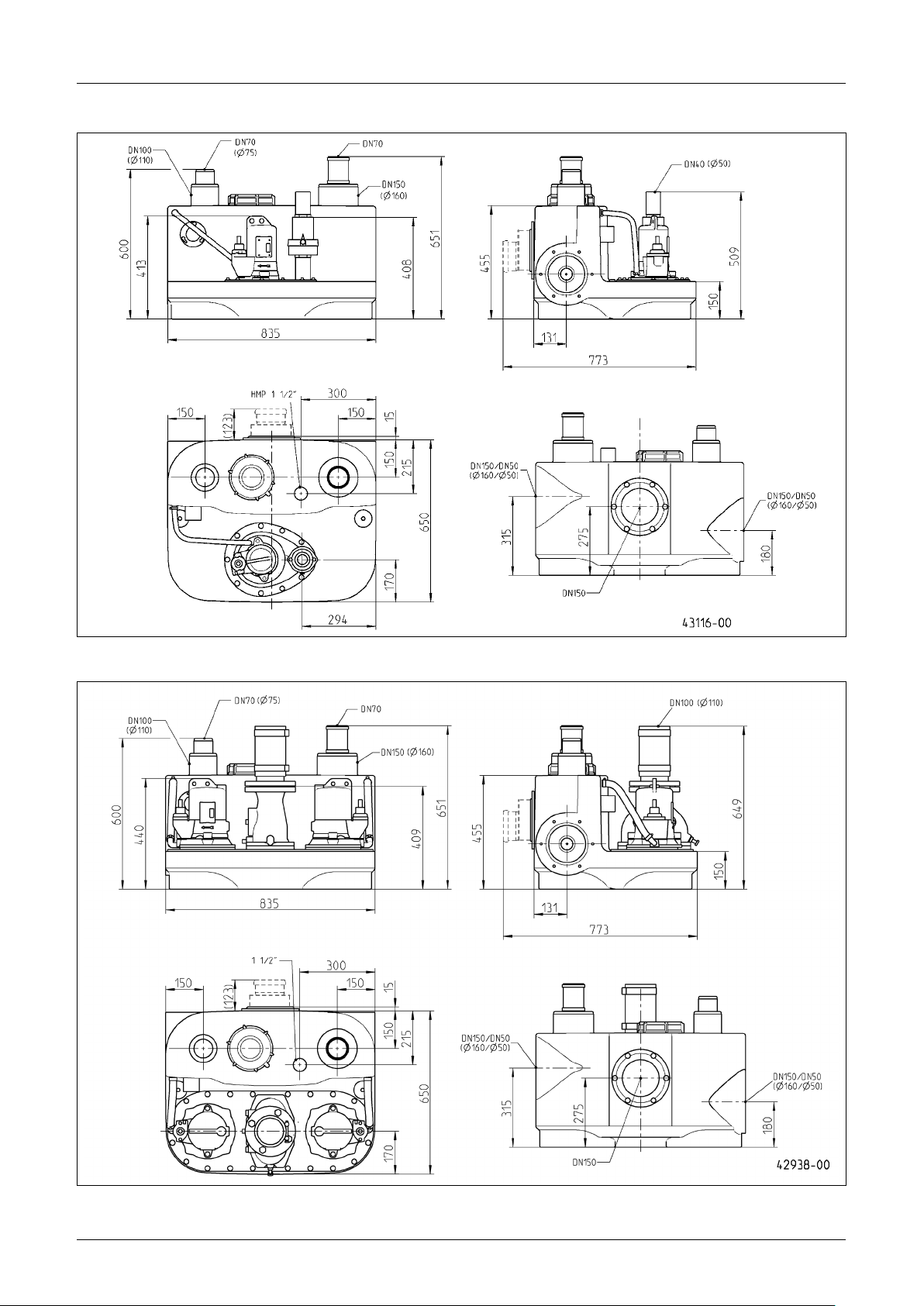
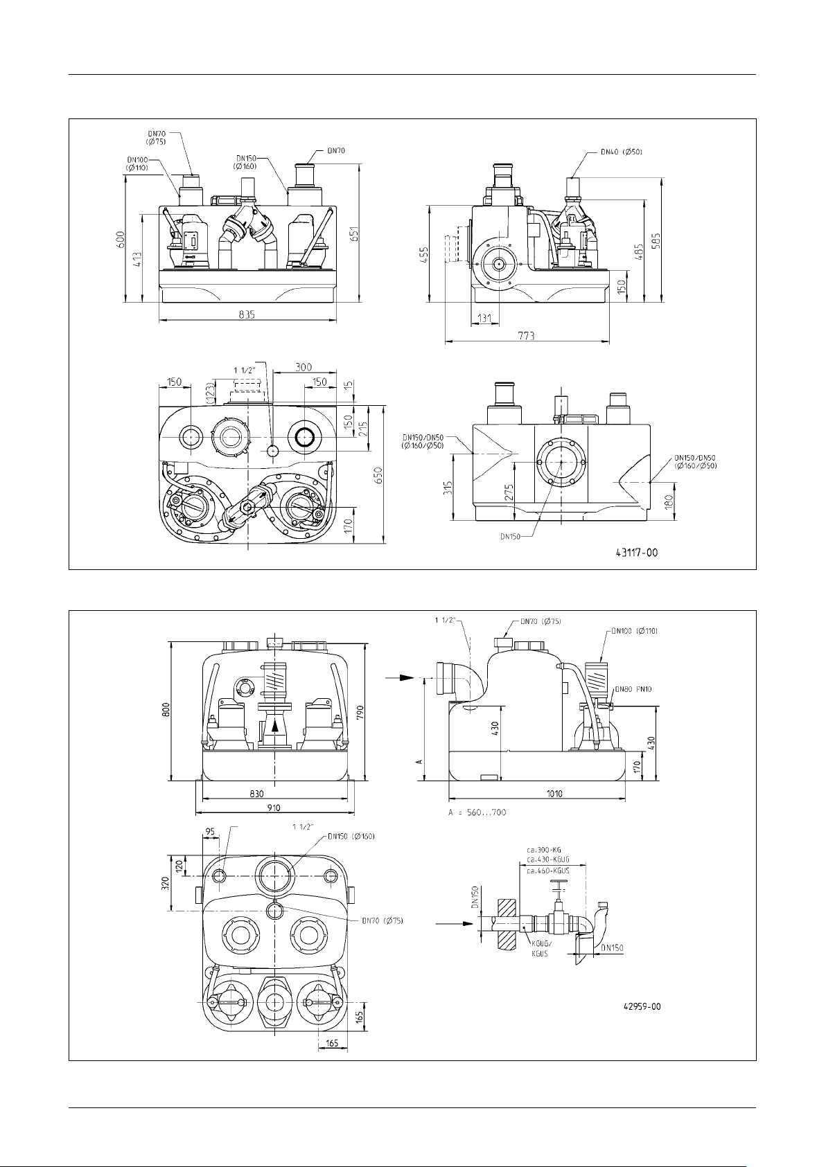
Scope of supply
• Tank with pump(s) and clamp ange for inlet
• Reducer DN 150 / DN 100 for compli 500 and 1000
• Slip-on socket pipe for ventilation pipe (compli 1200 exible
connection with hose clamps)
• Connection ange for pressure pipe
• Flexible connection with hose clamps for the pressure pipe
• Plug-in seal(s) for the diaphragm hand pump or additional DN
50 inlet
• Fixing materials for tank
• Non-return valve for the pressure pipe (compli 300, 500,
1000 and 1200)
• Controls (not compli 300)
Mode of operation: intermittent operation S3; see "Technical
Data"
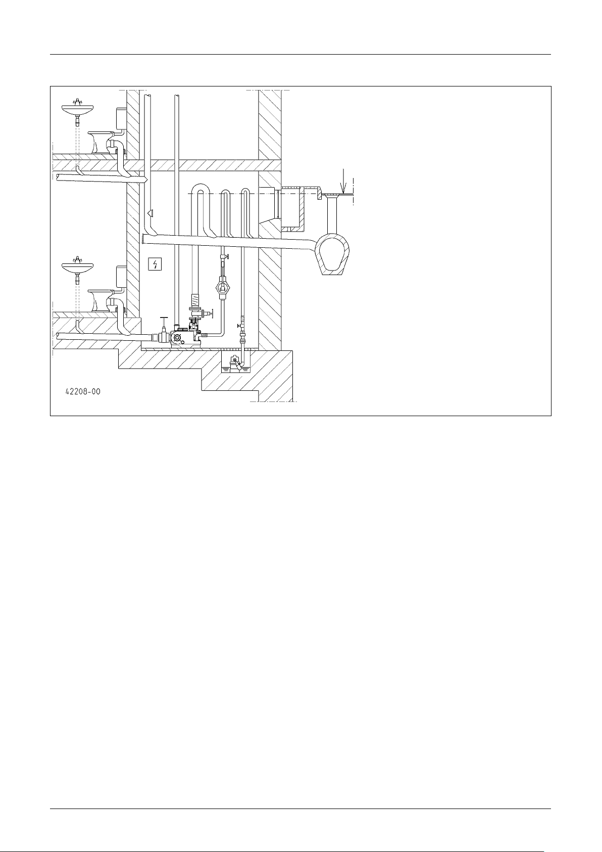
Ventilation: The ventilation pipe must be vented above roof level.
Inlet: A wastewater sluice valve must be installed in the inlet at
the front of the tank.
Pressure pipe: A further wastewater sluice valve must be installed behind the non-return valve in the pressure pipe. If the
non-return valve is not included in the scope of delivery of the
pumping unit, then an EN certied swing-type check valve
must be tted.
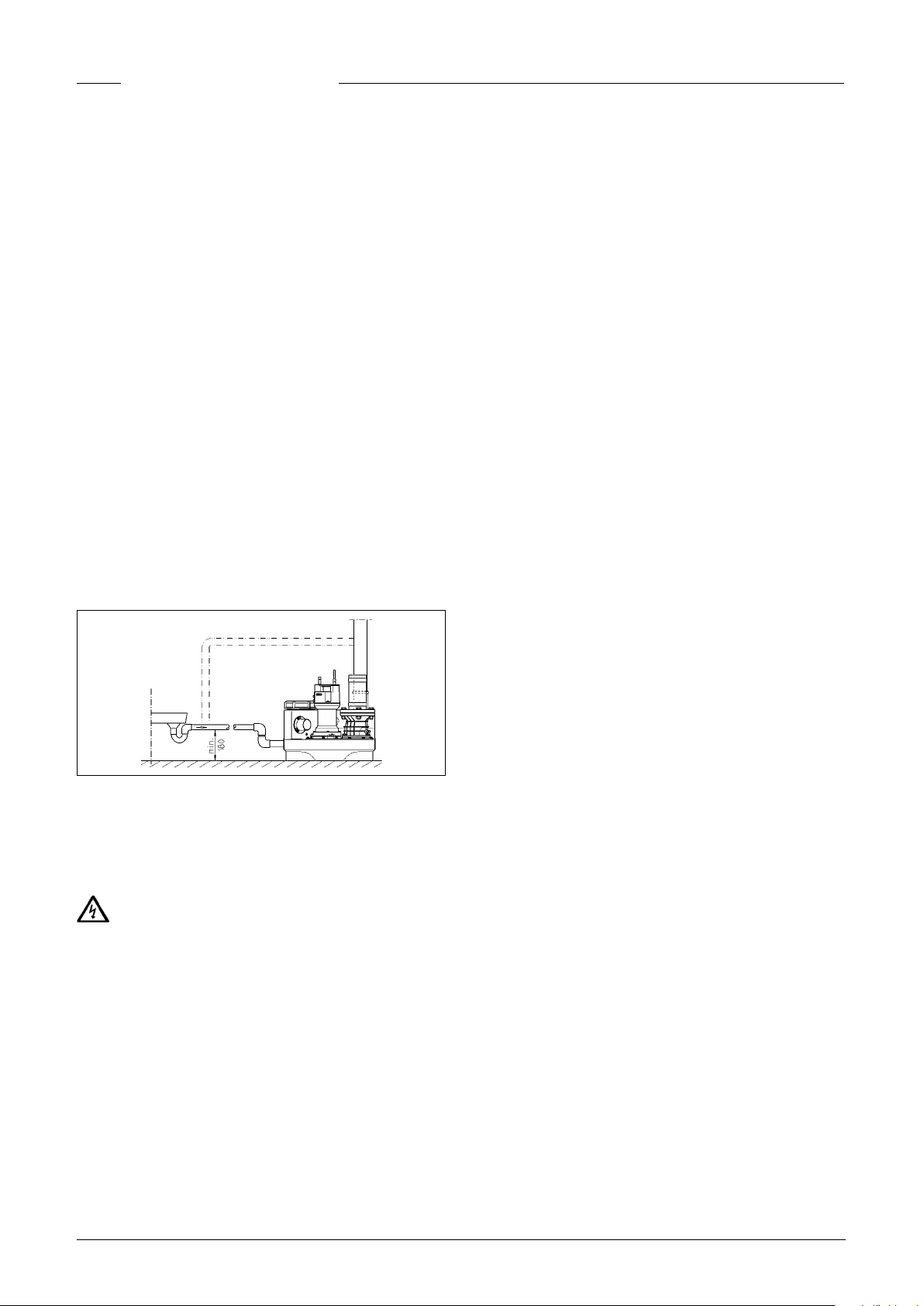
The pressure pipe must be laid in a loop above the local backup
level.
A pump sump must be provided to facilitate the disposal of water from the pump installation area.
NOTICE! All bolts that are used for xing individual compo-
nents to the tank should be tightened with a torque of no more
than 6 Nm.
Installing the tank
Close the sluice valve in the inlet (accessory) to prevent any
leakage of water during the installation work.
compli 300. Select the DN 100 inlet you wish to use and open
this inlet at the side or at the top at the markings using a 102
Øhole saw or a jigsaw. Then deburr the edges. Fix the enclosed
clamp ange loosely to the inlet with the hexagon screws.
Take the brackets that are used to x the unit in place and
screw them to the tank. Then take the unit with the clamp
ange and push it onto the inlet pipe as far as it will go.
Mark the positions of the wall plugs on the oor, then drill the
holes and push in the wall plugs.
Now the clamp ange can be tightened and the unit can be anchored to the oor using the wood screws and shims.
All other compli units must be slid onto the inlet pipe, together
with the clamp ange, as far as possible and then aligned.
If a DN 150 side inlet is used, the inlet must rst be opened
at the marked position using a hole saw, Ø 152, and then deburred. The standard inlet must then be closed using a closure
kit (accessory) and the switch-on level must be reset.
In the case of compli 500 and 1000, the inlet can be reduced
from DN 150 to DN 100 if the enclosed reducer is rst of all tted to the clamp ange.
Tighten the hexagon screws on the clamp ange.
Mark the positions of the holes for xing the tank to the oor,
then drill the holes.
Insert the wood screw, together with the washer and wall plug,
into the drill hole in the tank and tighten it.
NOTICE! Ensure that the tank does not become deformed due
to overtightening the screws, otherwise this could result in
leakage.
The tanks for compli 1200 units are additionally xed with two
brackets at the sides.
Installing the ventilation
Connect the ventilation pipe to the top right of the tank using the
DN 70 slip-on socket pipe and vent it above roof level.
For compli 1200, cut off the top right Ø 78 mm pipe connection at
the marking and deburr it. After this, connect the ventilation pipe
with the DN 70 exible connector and vent it above roof level.
INSTALLATION
The pump must be installed so that it is buoyancy-proof and
free-standing. At least 60 cm free working space must be provided around and above the parts that require access for operation or maintenance.
Installing the pressure pipe
Fit the following to the discharge ange:
1. Non-return valve (if not included in scope of supply)
2. Stop valve (accessory)
3. Connection ange and
4.
connect the pressure pipe with the exible connector and
loop it over the local backup level.
3
Page 4
ENGLISH
Emergency drainage connection, DN 50,
vertical
This inlet is used to connect a diaphragm hand pump.
Open the pipe connection at the marking using a hole saw.
Then deburr the edges.
Put the plug-in seal, 58/50, into place.
Push the inlet pipe, with an external diameter of 50 mm, into
the tank through the plug-in seal. The distance from the bottom of the tank must be at least 50 mm.
Fix the diaphragm hand pump to the wall in an easily accessible position. Connect it to the pushed-in pipe and then connect
the pressure pipe to the diaphragm hand pump. Here, too, the
pressure pipe must be looped over the local backup level.
Additional inlet, DN 50, horizontal
Using a hole saw, open the additional inlet by cutting along the
pre-cut groove. Deburr the edges.
Put the plug-in seal, 58/50, into place.
Push the inlet pipe, with an external diameter of 50 mm, into
the tank through the plug-in seal.
NOTICE! The pipes that connect to the low-level inlets on the
side of the unit must be tted with a bend, as close to the unit
as possible. The pipe invert of this bend must be at a height
of at least 180 mm above the oor on which the unit is xed.
Air pockets in the connecting pipe can cause run-off problems
and the water could back-up. To prevent back-ups, the inlet
pipe must be vented at its highest point. The ventilation pipe
can be connected into the tank ventilation.
Alternating current (AC) units
Only connect the pump to electrical sockets that have been
installed properly in a dry room, above the backup level, in ac-
cordance with the regulations, and are tted with at least a 16
A (delay) fuse.
Three-phase current units
For the electrical connection of the sewage disposal unit, a
ve pole CEE power socket is required. This must be located in
a dry room above the backup level (3/N/PE~230/400 V).
NOTICE! Only slow-blow fuses or automatic fuses with C characteristics are to be used as pre-fuses for the pump.
Installing the control unit (not compli 300)
Only operate the control unit in dry rooms above the backup
level, and keep the housing closed at all times. The control unit
must be easily accessible to enable it to be checked at any time.
High humidity and condensation can destroy the controls!
Switching levels
The switch-on and switch-off points have been factory set for
the standard inlet height for the various units.
If you select a different inlet height, then you must redene the
switch-on point (not compli 300) as otherwise backpressure
may occur in the inlet.
The other switching points for the alarm (+2 cm) and, in the
case of duplex units, peak load (+4 cm) are then reset automatically by the control unit.
ELECTRICAL CONNECTION
NOTICE! Only qualied electricians may carry out electrical
works to the pump or the controls.
WARNING!
Before carrying out any works: disconnect the pump and the
controls from the mains and take steps to ensure that they
cannot be emergized again.
NOTICE! Never put the mains plug in water! If water gets into
the plug, this can cause malfunctions and damage.
The standards applicable in each case (e.g. EN), the country-
specic regulations (e.g. VDE in Germany), and the regulations
of the local supply network operator must be observed.
Observe the operating voltage (see the type plate)!
The units have a level controller that switches the pump on and
off depending on the level of the water. An integrated alarm
system beeps if there is a malfunction, even if this is only temporary.
If the pump overheats, the motor cuts out due to the winding
thermostat. After the thermostat has switched off the system,
pull out the mains plug before remedying the fault, since the
device can switch itself on again automatically if the power is
still connected. A direct malfunction message is not gener
ated.
Redening the switch-on level (not compli
300)
Shut down the system temporarily and set the Manual-0-Automatic switch to “0”. The switch-on point can be adjusted via
the “analogue evaluator K1” module on the right-hand side in
the control unit. Remove the transparent cover of the module
temporarily.
On the analogue evaluator there are three LEDs, labelled P1, P2
and P3.
– P1 = Diagnosis function
– P2 on = Water level higher than switching off height but still
lower than switching on height
– P3 on = Water level has reached switching on level
Fill the collection chamber with water up to the bottom edge of
the inlet opening. Only P2 should be lit. If P3 is also lit, a readjustment must be made.
Turn the small adjusting screw beneath P1, giving it one or two
full turns clockwise. Then take the oat switch, submerge it
below the switch-off point in the chamber and allow it to oat
up again. If P3 is still lit, give the adjusting screw another full
turn clockwise and submerge the oat switch again.
Repeat this procedure until P3 is no longer lit, then turn the adjusting screw carefully back in the anticlockwise direction until
the exact point where P3 lights up again. The switch-on point
has then been set.
Alarm system
Malfunction messages are given both optically as well as
acoustically. The standard mains-dependent alarm system reports motor faults in the pump (red LED, not AD 00 or compli
300). At the same time a built-in acoustic alarm sounds. This
acoustic signal can only be turned off by remedying the fault or
by totally deactivating it.
If an acoustic signal would be inappropriate at the installation
site in question, an alarm signal can be relayed via the potential-free contact (terminals 40 and 41) on the circuit board (in
4
Page 5
the plug in the case of compli 300). The potential-free contact
ENGLISH
of the centralised alarm can be loaded with a maximum of 5 A /
250 VAC. The contact opens after the fault has been remedied.
OPERATION
Battery pack for alarm system (not compli
300)
The alarm device is mains-dependent in its standard version,
i.e. it is not possible to trigger a high-water alarm in the event
of a power failure. To enable the alarm device to work even if
there is a power failure, a rechargeable battery pack must be
used. Open the transparent cover. Connect the battery pack to
the connection clip, and use the existing cable ties to attach it
to the intended position (G1) on the PCB. The battery pack can
supply the alarm system with power for about 1 hour in case of
permanent alarm.
After return of the mains voltage, the battery pack is charged
again automatically. An empty battery is ready for operation
within approx. 24 hours. It is fully charged after about 100
hours.
Check the function of the battery pack at regular intervals! To
do so, disconnect the unit from the mains and trigger a highwater alarm. The volume of the acoustic signal must not be-
come signicantly quieter over a period of several minutes.
The service life is about 5 years. Note the insertion date on the
battery pack and after ve years the battery pack should be replaced as a precautionary measure.
CAUTION!
Only use the 9V-NiMh battery supplied by the manufacturer! If
dry-cell batteries or Lithium batteries are used there is a danger of explosion!
Time meter
An optional time meter can be tted in the control unit (not
compli 300). To do so, shorten the connections of the time meter to approx. 8 mm and insert them into the four sockets at
location BSZ on the printed circuit board. If there is no time
meter indication after switching on the unit again, rotate the
time meter through 180°.
Shutting down the internal alarm buzzer
Not compli 300. Remove the sealed jumper (BRX/BRX1). To
prevent the jumper from getting lost, attach it to a pin of the
two-pole pin connector.
External alarm buzzer (accessory)
Open the transparent cover on the control unit.
An additional separate acoustic 12 VDC signal transmitter with
a current consumption of not more than 30 mA can be connected to terminals “S+” and “S-”. The internal alarm buzzer can
either be switched on or off.
In the case of compli 300, a mains-independent alarm device
can be tted as an accessory. There is a mounting base on the
tank for this purpose.
In the case of duplex units: External 230V~
ashing light or warning light (accessory)
Connect a 230V~ lamp (1 A max.) to terminals N and 41.
Lay an insulated wire bridge from terminal U~ to terminal 40.
The electric circuit is protected by F1.
Set Jumper BRX2 as follows: Flashing light without BRX2
(Continuous ===) Warning light with BRX2 (Flashing (_Π_Π_ )
Test run and functional check
1. Open the maintenance cover of the tank.
2. Open the shut-off valves in the inlet and the pressure pipe.
3. Connect the unit to the power supply and observe the indi-
cation for the rotating eld direction.
4. Fill the tank up to the switch-on level.
5. The pump will now switch on and empty the tank. Observe
the pumping process through the maintenance opening.
6. Lift the oat of the level controller slowly by hand until it is
above the switch-on point and hold it there until the alarm
is triggered.
7. Then close the maintenance opening with the cover and
seal.
8. Check to ensure that the tank, ttings and pipes are water-
tight, by carrying out several switching runs.
Automatic operation
Automatic operation is the normal operating mode of the unit.
The rocker switch must be set to “Automatic”. The integrated
level controller switches the pump on and off depending on the
water level in the tank. A green LED lights up when the pump is
operating (in the case of compli 300 when it is ready for operation).
NOTICE! If unusually large quantities of wastewater ow into
the unit (e.g. when a pool is drained), partially close the shutoff valve at the inlet until the unit can operate normally again,
switching on and off, (not pumping continuously, since this
could overheat the pump motor).
Manual operation
Set the rocker switch to “Hand”. The pump will now operate
permanently and independently of the wastewater level. The
pumping out operation should therefore be observed through
the maintenance opening.
Shutting down
Set the rocker switch to “0”. This shuts down the pump. The
alarm system remains ready for operation.
DANGER!
Do not use the position “0” of the selector switch for repair and
maintenance work on the control and pump, but always unplug
the unit from the mains.
Inspection
To maintain operational reliability, carry out a visual inspection
of the unit, including the pipe connections, once a month.
MAINTENANCE
Maintenance and inspection of this product must be carried
out in accordance with EN 12056-4. To ensure continued reliability of service, we recommend that you take out a service
contract.
NOTICE! The maintenance of the sewage lifting station and
maintenance measures are carried out by specialists at intervals of 3 months in commercial premises, multi-family homes
in 6 months or 12 months in family homes.
5
Page 6
ENGLISH
WARNING!
Before carrying out any works: disconnect the pump and the
controls from the mains and take steps to ensure that they
cannot be energized again.
WARNING!
Check the cable for mechanical or chemical damage. A damaged or kinked cable must be replaced.
We recommend that the following works be included in the
service:
1. Check the connection points for watertightness and in-
spect the areas surrounding the unit and the ttings.
2. Operate the shut-off valves and check that they move easily. Adjust and grease them if necessary.
3. Open and clean the swing-type check valve; check the seat
and ball (valve)
4. Clean the pump and the pipes where they connect to the
unit; check the impeller and the bearings.
CAUTION!
5. Worn impellers can have sharp edges.
6. Oil check. If necessary top up or change oil (if oil chamber
available).
7. Clean the inside of the tank (as necessary, or if especially
required); remove any grease, for example.
8. Check the condition of the collecting tank.
9. Flush the system through with water once every 2 years.
10. Inspect the electrical section of the unit. The control unit
itself is maintenance-free, but if a rechargeable battery is
tted, then it should be checked regularly to ensure that it
is in good working order. To do so, unplug the unit from the
mains and lift the oat of the level controller slowly by hand
and hold it there until the alarm is triggered. In addition,
clean the oat if necessary.
When all the servicing tasks have been performed, carry out a
test run and then put the unit back into operation. The service
must be documented, giving details of the important data and
of all the tasks carried out.
Oil check
(Only applies for units 08/2, 25/2 and 35/2). First of all, unscrew
the hexagon screws or Allen screws around the pump and lift
the pump and impeller off the tank. The drain plug is labelled
“Öl”. In order to check the mechanical seal, the oil, including any
residue, must be drained from the oil reservoir and collected in
a clean measuring container.
• If the oil is contaminated with water (milky), an oil change
must be carried out. Check again after a further 300 operating hours, but at the very latest after 6 months!
• However, if the oil is contaminated with both water and pol-
lutants, then not only the oil must be replaced, but the mechanical seal as well.
For monitoring the oil reservoir, it is also possible to retrot the
electrode of our “DKG” seal leak detector in place of the “DKG”
sealing screw.
pumped, the oil changes should be carried out at correspondingly shorter intervals.
Use HLP hydraulic mineral oil, viscosity class 22 to 46, e.g. Mobil DTE 22, DTE 24, DTE 25, to replace the oil in the oil reservoir.
The quantity of oil required is 380 cm³ for the MultiCut pumps
UC 08/2 M and UC 25/2 M, and 1000 ml for the MultiFree pumps
UC 25/2 BW and 35/2 BW.
NOTICE! The oil reservoir may only be lled with the specied
quantity of oil. Overlling will result in the pump being rendered
inoperable.
Checking the cutting clearance
Only for pumps with cutting system. The housing screws for
the pump, and the connecting and xing screws of the installation must be checked to ensure they are xed securely. They
should be tightened if necessary.
If the pump performance decreases, or if increasingly loud
noises can be heard during operation, or if the cutting performance decreases (the pump tends to become blocked), the
impeller and cutting system must be checked for wear by an
expert and replaced if necessary.
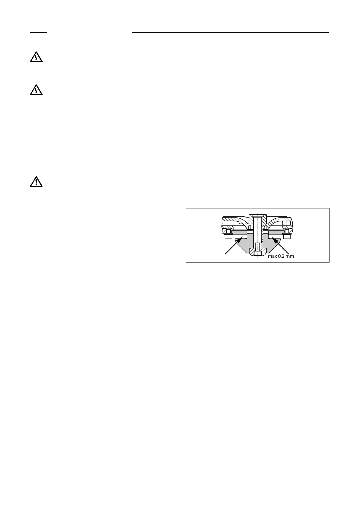
Using a suitable tool, e.g. feeler gauge, the cutting clearance
between the cutting rotor and the cutting plate can be measured. A cutting clearance of over 0.2 mm must be reduced.
Adjustment of the cutting clearance
1. Block the cutting rotor with a piece of wood and unscrew the
central hexagon socket screw.
2. Take off the compression piece, the cutting rotor and an adjusting washer and then attach the compression piece and the
cutting rotor again.
3. Block the cutting rotor and tighten again with the hexagon
socket screw (tightening torque 8 Nm).
4. Check the freedom of movement of the cutting rotor and the
cutting clearance again (max. 0.2 mm).
If the cutting clearance is still too big, a further adjusting
washer must be removed. Steps 1-4 must be repeated.
Changing the oil
(Only applies for units 08/2, 25/2 and 35/2). To ensure opera-
tional liability, the rst oil change should be carried out after
300 operating hours, with further oil changes carried out after
every 1000 operating hours.
If the number of operating hours is very low, an oil change
should still be carried out at least once a year.
If wastewater with strongly abrasive constituents is being
6
Page 7

QUICK TIPS FOR REMEDYING
ENGLISH
FAULTS
support service.
• There is no water left in the tank. Fill with a small amount of
water.
• Note: If the LED lights up briey after the pumping opera-
tion, this is not a sign of a malfunction.
The unit isn’t working
• Check the mains voltage, the fuse and the ground fault cir-
cuit interrupter. Replace defective fuses only with fuses
with the same nominal value! If the fuse triggers again, call a
qualied electrician or our customer support service.
• The internal 2 A glass tube fuse (delay) for the 230/12V con-
trol transformer, the motor contactor and the 230V AC power supply are faulty. Replace defective fuses only with fuses
with the same nominal value!
• If the mains cable is damaged, it may only be replaced by the
manufacturer.
• If the oat switch is obstructed, close the inlet shut-off
valve, open the maintenance cover and clear the blockage.
If the alarm is triggered and the unit does not
work:
• The thermostat in the motor windings may have switched
off the system because the pump is obstructed. In this case,
close the shut-off valve at the inlet, drain the tank, pull out
the mains plug, remove the pump module, and clear the
blockage.
Decreased pumping performance
• Check that the shut-off valve in the pressure pipe is fully
open.
• If the pressure pipe is blocked, ush water through the pres-
sure pipe to clear it.
• If the non-return valve is blocked, empty the pressure pipe
and clean the non-return valve.
• If the ventilation system is blocked, clean the ventilation
hose that leads from the pump tank and check the drilled
holes.
• If the unit works normally when it starts pumping, but be-
comes very loud towards the end, then a qualied electrician
must redene the switch-off point in the control unit.
Pump "snores" and does not switch itself off
(not compli 300)
• The switch-off point of the unit is too low.
Unscrew the three xing screws on the level monitoring at the
front of the collecting tank. By carefully rotating it to the right
the switch-off point can be set to a higher level. Retighten the
screws. The switch-off level is reached during pumping when
the LED2 goes off.
NOTICE! It may also be necessary to re-adjust the switch-on
level (please refer to the section “Redening the switch-on level”).
Indicator “Drehfeld falsch" (Wrong rotating
eld) lights up
• Mains phase sequence is wrong or phase is absent - thus
lower or absent pump delivery. The mains connection must
be corrected by a qualied electrician only.
Indicator “Störung Pumpe" (Pump failure)
lights up (not compli 300)
• The pump is protected by an integrated circuit breaker which
switches off the pump if it overloads or
motor fault. After this has been triggered, the control unit
has to be opened by a qualied electrician in order to press
the reset button.
if there is an electric
Indicator “Hochwasser" (High water) lights up
(not compli 300)
• Water level in the tank too high because of low pump ow
rate or excessive inow. Remove any obstructions in the
pump or pressure pipe and/or eliminate the excessive inow.
LED P1 on the analogue evaluator is
permanently lit up (not compli 300)
• There is a fault in the level monitoring. Call our customer
7
Page 8
Technische Daten - Technical data -Caractéristiques techniques- Technische
Gegevens - Dati tecnici - Dane techniczne - Technické údaje - Technické údaje Műszaki adatok -Date tehnice - 技术指标
compli 100
compli 300
8
Page 9
compli 400
compli 500
9
Page 10
compli 500 M
compli 1000
10
Page 11
compli 1000 M
compli 1200
11
Page 12
12
Page 13

... 300 E ... 400 E ... 1010 BWE
... 400
[kg] 29 55 118 56
PN 10 DN 80 DN 80 DN 80 DN 80
[mm] 50 70 70 70
S3* 10 % 25 % 25 % 30 %
P1 [kW] 1,37 1,55 1,55 1,25
P2 [kW] 0,98 1,10 1,10 0,87
U [V] 1/N/PE ~230 1/N/PE ~230 1/N/PE ~230 3/N/PE ~400
f [Hz] 50 50 50 50
I [A] 6,0 7,1 7,1 2,2
n [min
-1
] 2700 1428 1428 1390
AD 69 ECP BD 610 ECP AD 00 P
... 510/4 BW ... 515/4 BW ... 525/4 BW ... 525/2 BW ... 535/2 BW
... 1010/4 BW ... 1015/4 BW ... 1025/4 BW ... 1025/2 BW ... 1035/2 BW
... 1210/4 BW ... 1215/4 BW ... 1225/4 BW ... 1225/2 BW ... 1235/2 BW
[kg] 79/128/145 79/128/145 79/128/145 86/125/149 89/132/158
PN 10 DN 80 DN 80 DN 80 DN 80 DN 80
[mm] 70 70 70 70 70
S3* 45 % 30 % 15 % 25 % 25 %
P1 [kW] 1,3 2,2 3,0 3,3 4,8
P2 [kW] 1,0 1,7 2,2 2,6 4,0
U [V] 3/N/PE ~400 3/N/PE ~400 3/N/PE ~400 3/N/PE ~400 3/N/PE ~400
f [Hz] 50 50 50 50 50
I [A] 2,8 3,9 5,1 5,4 7,8
n [min
-1
] 1451 1405 1363 2807 2857
AD 25 P / BD 25 P AD 25 P / BD 25 P AD 46 P / BD 46 P AD 46 P / BD 46 P AD 610 P / BD 610 P
... 108/2 ME ... 108/2 M ... 120/2 M
... 508/2 ME ... 508/2 M ... 520/2 M
... 1008/2 ME ... 1008/2 M ... 1020/2 M
[kg] 42/50/77 41/49/75 43/51/79
PN 10 DN 32/40/40 DN 32/40/40 DN 32/40/40
[mm] 7 7 7
S3* 10 % 35 % 25 %
P1 [kW] 1,70 1,65 2,30
P2 [kW] 1,14 1,24 1,85
U [V] 1/N/PE ~230 3/N/PE ~400 3/N/PE ~400
f [Hz] 50 50 50
I [A] 7,5 2,8 3,9
-1
n [min
] 2584 2674 2860
AD 08/2 MEP AD 00 P / BD 00 P AD 46 P / BD 46 P
* Example for 40%: 4 min. operation and 6 min. rest (Cycle duration 10 min.); Exemple: 40%= 4 min de service et 6 min de pause (Durée du jeu 10 min)
Esempio: 40%: 4 min. di funzionamento + 6 min. di pausa (durata del ciclo 10 min.) Przykładowo 40%: 4 min pracy i 6 min przerwy (Czas cyklu 10 min);
Příklad 40%: 4 min. provoz a 6 min. přestávka (trvání pracovního cyklu 10 min.) Príklad 40%: 4 min prevádzka a 6 min prestávka (doba trvania cyklu 10 min);
4 perc üzem és 6 perc szünet (ciklusidő 10 perc) Exemplu 40%: 4 min funcţionare şi 6 min pauză (timp aproximativ 10 min)
13
Page 14

Leistung - Performance - Puissances - Capaciteit - Prestazioni - Wydajności i moce -
Alarm delay
Buzzer
45564
Výkony - Výkony - Teljesítmény - Capacităţi -
性能参数
H [m]
compli 300 E
compli 400 E
compli 1010 BWE
compli 400
... 10/4 BW
... 15/4 BW
... 25/4 BW
... 25/2 BW
... 35/2 BW
... 08/2 ME
... 08/2 M
... 20/2 M
1 2 3 4 5 6 7 8 9 10 11 12 13 14 15 16 17
30 29 28 24 22 19 15 Q [m³/h]
48 40 33 27 20 13
52 44 37 29 22 13
48 40 33 27 20 13
52 44 37 29 22 13
69 62 56 49 42 36 27 19
56 49 42 32 22 13
69 64 58 52 47 42 37 33 28 23 20 14 8 1
85 80 75 71 66 62 57 54 50 47 44 39 36 33 30 26 21
17 16 14 12 9 7 4
17 16 14 12 9 7 4
16 14 12 10 8
compli 300
14
Page 15

AD 69 ECP
Einzelanlage - Single unit - Unité de commande Poste simple - Regelaar van een enkelvoudige installatie - Comando singolo - Sterownik instalacji jednopompowej - Řídící jednotka jednoduché zařízení - Riadenie samostatného zariadenia - Egyedi berendezés
vezérlője - Sistem de comandă instalaţie individuală - 单泵系统
15
Page 16

AD 08/2 MEP
Einzelanlage - Single unit - Unité de commande Poste simple - Regelaar van een enkelvoudige installatie - Comando singolo -Sterownik instalacji jednopompowej - Řídící jednotka jednoduché zařízení - Riadenie samostatného zariadenia - Egyedi berendezés
vezérlője - Sistem de comandă instalaţie individuală - 单泵系统
16
Page 17

AD ... P
Einzelanlage - Single unit - Unité de commande Poste simple - Comando singolo - Regelaar van een enkelvoudige installatie
- Sterownik instalacji jednopompowej - Řídící jednotka jednoduché zařízení - Riadenie samostatného zariadenia - Egyedi
berendezés vezérlője - Sistem de comandă instalaţie individuală - 单泵系统
17
Page 18

BD 610 ECP - compli 1008/2 ME
Schuko-plug /
Prefuse /
Doppelanlage - Duplex unit - Comando doppio Unité de commande Poste double - Regelaar van een dubbele installatie - Comando
doppio - Sterownik instalacji dwupompowej - Řídící jednotka dvojité zařízení - Riadenie dvojitého zariadenia - Kettős berendezés -
Sistem de comandă instalaţie dublă - 双泵系统
18
Page 19

BD 610 ECP - compli 1010/4 BWE
/ brown
white
/green
black
grey (old: blue)
brown
Prefuse /
Doppelanlage - Duplex unit - Unité de commande Poste double - Comando doppio - Regelaar van een dubbele installatie - Sterownik
instalacji dwupompowej - Řídící jednotka dvojité zařízení - Riadenie dvojitého zariadenia - Kettős berendezés - Sistem de comandă
instalaţie dublă - 双泵系统
19
Page 20

BD ... P
Doppelanlage - Duplex unit - Unité de commande Poste double - Comando doppio - Regelaar van een dubbele installatie - Sterownik
instalacji dwupompowej - Řídící jednotka dvojité zařízení - Riadenie dvojitého zariadenia - Kettős berendezés - Sistem de comandă
instalaţie dublă - 双泵系统
20
Page 21

COMPLI 100 M
Ersatzteile - Spare parts - Pièces de rechange - Reserveonderdelen - Parti di ricambio - Reservedele - Reserv delar
Varaosat - Części zamienne - Náhradní díly - Alkatrészek - Piese de schimb - Запасные части -
①
Pumpe Pump
备件
08/2 ME
08/2 M JP46822
20/2 M
②
Rückschlagklappe Reux valve JP48139
③
Wartungsdeckel Service lid JP42798
④
Steuerung Control unit
08/2 ME JP46825
08/2 M JP46810
20/2 M
⑤
Steuerungsplatine Control board
08/2 ME JP47693
08/2 M JP46846
20/2 M JP47717
⑥
Rundschnur Round cord JP47968
⑦
Überschiebmuffe Collar JP47287
⑧
Klemmansch Clamping ange JP43708
⑨
Niveauerfassung Level control JP43734
⑩
Elast. Verbindung Elastic connector JP43731
⑪
Steckdichtung Plug in seal JP45099
⑫
Behälter Tank JP46820
⑬
Auftriebssicherung
⑭
Pumpenlüftung Pump ventilation JP43732
Anti oating JP43733
JP46821
JP46824
JP45789
JUNG-PUMPEN.DE
21
Page 22

COMPLI 500 M
①
Steuerung Control unit
08/2 ME JP46825
08/2 M JP46810
20/2 M
②
DN 150 / DN 100 DN 150 / DN 100 JP48871
③
Klemmansch Clamping ange JP43713
④
Wartungsdeckel Service lid JP42798
⑤
Überschiebmuffe Collar JP47287
⑥
Behälter Tank JP46832
⑦
Steuerungsplatine Control board
08/2 ME JP47693
08/2 M JP46846
20/2 M JP47717
⑧
Niveauerfassung Level control JP43712
⑨
Pumpenlüftung Pump ventilation JP43732
⑩
Auftriebssicherung
⑪
Pumpe Pump
08/2 ME JP46833
Anti oating JP43709
JP45789
08/2 M JP46834
20/2 M
⑫
Elast. Verbindung Elastic connector JP43735
⑬
Rundschnur Round cord JP47967
⑭
Rückschlagklappe Check valve JP48138
JP46835
22
Page 23

COMPLI 1000 M
①
Steuerung Control unit
08/2 ME JP48626
08/2 M JP45786
20/2 M
②
DN 150 / DN 100 DN 150 / DN 100 JP48871
③
Klemmansch Clamping ange JP43713
④
Wartungsdeckel Service lid JP42798
⑤
Überschiebmuffe Collar JP47287
⑥
Behälter Tank JP46836
⑦
Steuerungsplatine Control board JP47304
⑧
Niveauerfassung Level control JP43712
⑨
Pumpenlüftung Pump ventilation JP43732
⑩
Auftriebssicherung
⑪
Pumpe
08/2 ME JP46833
Anti oating JP43709
Pump
JP45786
08/2 M JP46834
20/2 M
⑫
Elast. Verbindung Elastic connector JP43735
⑬
Rundschnur Round cord JP47967
⑭
Rückschlagklappe Check valve JP46837
JP46835
23
Page 24

UC 08/2 M - 20/2 M
①
Leitung Cable JP43717
②
Stator + Gehäuse Stator + Housing
08/2 ME JP43736
08/2 M JP43737
20/2 M
③
Lagersatz Bearing set JP45585
④
Rotorwelle Rotor shaft
08/2 ME JP47391
08/2 M JP46561
20/2 M
⑤
Gleitringdichtung Mechanical seal JP46043
⑥
Coni Stecker Coni plug JP46572
⑦
Dichtungssatz Seal set JP45628
⑧
Lagerkammer Bearing housing JP43739
⑨
Schneidplatte
⑩
Laufrad
08/2 M
20/2 M
⑪
Pass-Scheiben Shim rings JP46559
⑫
Pumpengehäuse Pump casing
100 JP47309
500, 1000
⑬
Schneidrotor Cutter JP45472
⑭
Ölschraube Oil screw JP46046
⑮
Schraubensatz Screw set JP46563
Cutter plate JP45470
Impeller
JP43738
JP46562
JP45467
JP45468
JP47390
24
Page 25

COMPLI 300 E
Ersatzteile - Spare parts - Pièces de rechange - Reserveonderdelen - Parti di ricambio - Reservedele - Reserv delar
Varaosat - Części zamienne - Náhradní díly - Alkatrészek - Piese de schimb - Запасные части -
①
Elast. Verbindung Elastic connector JP42792
②
Motoreinheit Motor unit JP47288
③
Flansch Flange JP42793
④
Rückschlagventil Reux valve JP42794
⑤
Gummiklappe Valve ap JP46841
⑥
Basisplatte Basis plate JP42797
⑦
Dichtband Sealing tape JP47966
⑧
Überschiebmuffe Collar JP47287
⑨
Wartungsdeckel Service lid JP42798
⑩
Klemmansch Clamping ange JP42795
⑪
Pumpenlüftung Pump ventilation JP42799
⑫
Steckdichtung Plug in seal JP45099
⑬
Behälter Tank JP44749
⑭
Auftriebssicherung
⑮
Schraubensatz Screw set JP42800
⑯
Dichtungssatz Seal set JP42801
备件
Anti oating JP42796
JUNG-PUMPEN.DE
25
Page 26

MOTOR COMPLI 300 E
①
Steuerung Control unit JP42802
②
Leitung Cable JP46843
③
Niveauschaltung Level control unit JP42808
④
Kondensator Capacitor JP46016
⑤
Haube Top Cover JP46019
⑥
Schwimmer Float JP42771
⑦
Rotorwelle Rotor shaft JP47289
⑧
Lagersatz Bearing set JP46042
⑨
Motorabdichtung Motor seals JP46728
⑩
Stator + Gehäuse Stator + Housing JP46029
⑪
Dichtungssatz Seal set JP42810
⑫
Schraubensatz Screw set JP42809
⑬
Laufrad
⑭
Lagerschild Bearing housing JP42806
Impeller JP46053
22
Page 27

COMPLI 400
Ersatzteile - Spare parts - Pièces de rechange - Reserveonderdelen - Parti di ricambio - Reservedele - Reserv delar
Varaosat - Części zamienne - Náhradní díly - Alkatrészek - Piese de schimb - Запасные части -
①
Elast. Verbindung Elastic connector JP43705
②
Niveauerfassung Level control JP43712
③
Flansch Flange JP43706
④
Steuerung Control unit
compli 400 JP46810
compli 400 E
⑤
Pumpe Pump
compli 400 JP46753
compli 400 E JP46754
⑥
Rückschlagklappe Reux valve JP43707
⑦
Steuerungsplatine Control board
compli 400 JP46846
compli 400 E
⑧
Basisplatte Base plate JP43711
⑨
Überschiebmuffe Collar JP47287
⑩
Dichtband Sealing tape JP47966
⑪
Pumpenlüftung Pump ventilation JP43710
⑫
Wartungsdeckel Service lid JP42798
⑬
Klemmansch Clamping ange JP43708
⑭
Auftriebssicherung
⑮
Steckdichtung Plug in seal JP45099
⑯
Behälter Tank JP44859
备件
JP48526
JP48527
Anti oating JP43709
JUNG-PUMPEN.DE
23
Page 28

MOTOR COMPLI 400
①
Leitung Cable
compli 400 JP43717
compli 400 E
②
Stator + Gehäuse Stator + Housing
compli 400 JP43718
compli 400 E
③
Rotorwelle Rotor shaft
compli 400 JP46761
compli 400 E
④
Motorabdichtung Motor seals JP46806
⑤
Laufradschraube Impeller screw JP46803
⑥
Lagersatz Bearing set JP46724
⑦
Lagerschild Bearing housing JP43720
⑧
Dichtungssatz Seal set JP46807
⑨
Laufrad
⑩
Schraubensatz Screw set JP47291
Impeller JP47290
JP43721
JP43722
JP46801
24
Page 29

COMPLI 500
Ersatzteile - Spare parts - Pièces de rechange - Reserveonderdelen - Parti di ricambio - Reservedele - Reserv delar
Varaosat - Części zamienne - Náhradní díly - Alkatrészek - Piese de schimb - Запасные части -
Steuerung Control unit
①
510/4, 515/4 JP45788
525/2, 525/4 JP45789
535/2
DN150 / DN100 DN 150 / DN100 JP48871
②
Klemmflansch Clamping flange JP43713
③
Wartungsdeckel Service lid JP42798
④
Überschiebmuffe Collar JP47287
⑤
Behälter Tank JP44860
⑥
Steuerungsplatine Control board
⑦
510/4, 515/4 JP46839
备件
JP45790
525/2, 525/4 JP47717
535/2 JP47303
Niveauerfassung Level control JP43712
⑧
Pumpenlüftung Pump ventilation JP43710
⑨
Auftriebssicherung
⑩
Pumpe Pump
⑪
510/4 JP45778
515/4 JP45779
525/4 JP45780
525/2 JP48826
535/2
Elast. Verbindung Elastic connector JP43705
⑫
Basisplatte Base plate JP43711
⑬
Flansch Flange JP43706
⑭
Dichtband Sealing tape JP47966
⑮
Rückschlagklappe Reflux valve JP43707
⑯
Anti floating JP43709
JP48827
JUNG-PUMPEN.DE
25
Page 30

COMPLI 1000
Steuerung Control unit
①
1010/4 BWE JP47285
1010/4, 1015/4 JP47286
1025/4, 1025/2 JP45786
1035/2
DN 150 / DN 100 DN150 / DN 100 JP48871
②
Klemmflansch Clamping flange JP43713
③
Wartungsdeckel Service lid JP42798
④
Überschiebmuffe Collar JP47287
⑤
Behälter Tank JP44861
⑥
Steuerungsplatine Control board JP47304
⑦
Niveauerfassung Level control
⑧
4 m Leitung 4 m cable JP43712
15 m Leitung 15 m cable
JP45787
JP48227
Pumpenlüftung Pump ventilation JP43710
⑨
Auftriebssicherung
⑩
Pumpe Pump
⑪
1010/4 BWE, 4 m JP46754
1010/4 BWE, 15 m JP48684
1010/4 JP45778
1015/4 JP45779
1025/4 JP45780
1025/2 JP48826
1035/2
Elast. Verbindung Elastic connector JP43705
⑫
Gehäuse Klappe Housing valve JP46813
⑬
Flansch Flange JP43706
⑭
Doppelklappe
⑮
Basisplatte Base plate JP43714
⑯
Dichtband Sealing tape JP47966
⑰
Anti floating JP43709
Duplex flap JP46812
JP48827
26
Page 31

UC 10/4 - 15/4 - 25/4
27
Page 32

UC 25/2 - 35/2
Leitung Cable JP43717
①
Stator + Gehäuse Stator + Housing
②
25/2 JP44008
35/2
Rotorwelle Rotor shaft
③
25/2 JP48339
35/2
Gleitringdichtung Mechanical seal JP46567
④
Lagersatz Bearing set JP46214
⑤
Lagerschild Bearing housing JP43726
⑥
Dichtungssatz Seal set JP46807
⑦
JP46211
JP48340
Laufrad
⑧
25/2
35/2
Wellenabdeckung Shaft cover JP47043
⑨
Motorabdichtung Motor seals JP46806
⑩
Schraubensatz Screw set JP47291
⑪
Ölschraube Oil screw JP46046
⑫
a
10x O-Ring 38x3,5
O-Ring 10x2,5
c 10x
Impeller
JP48359
JP48360
JP48109
JP48088
28
Page 33

COMPLI 1200
Ersatzteile - Spare parts - Pièces de rechange - Reserveonderdelen - Parti di ricambio - Reservedele - Reserv delar
Varaosat - Części zamienne - Náhradní díly - Alkatrészek - Piese de schimb - Запасные части -
Niveauerfassung Level control JP47306
①
Klemmflansch Clamping flange JP43713
②
Überschiebmuffe Collar JP46814
③
Wartungsdeckel Service lid JP42798
④
Steuerung Control unit
⑤
1210/4, 1215/4 JP47286
1225/4, 1225/2 JP45786
1235/2
Steuerungsplatine Control board JP47304
⑥
Steckdichtung Plug in seal JP45099
⑦
Behälter Tank JP44862
⑧
Pumpenlüftung Pump ventilation JP43710
⑨
Auftriebssicherung
⑩
Auftriebssicherung
⑪
Elast. Verbindung Elastic connector JP43705
⑫
Gehäuse Klappe Housing valve JP46813
⑬
备件
JP45787
Anti floating JP43716
Anti floating JP43709
Pumpe Pump
⑭
1210/4 JP45778
1215/4 JP45779
1225/4 JP45780
1225/2 JP48826
1235/2
Flansch Flange JP43706
⑮
Doppelklappe
⑯
Basisplatte Base plate JP43714
⑰
Dichtband Sealing tape JP47966
⑱
Duplex flap JP46812
JP48827
JUNG-PUMPEN.DE
29
Page 34

UC 10/4 - 15/4 - 25/4
30
Page 35

UC 25/2 - 35/2
Leitung Cable JP43717
①
Stator + Gehäuse Stator + Housing
②
25/2 JP44008
35/2
Rotorwelle Rotor shaft
③
25/2 JP48339
35/2
Gleitringdichtung Mechanical seal JP46567
④
Lagersatz Bearing set JP46214
⑤
Lagerschild Bearing housing JP43726
⑥
Dichtungssatz Seal set JP46807
⑦
JP46211
JP48340
Laufrad
⑧
25/2
35/2
Wellenabdeckung Shaft cover JP47043
⑨
Motorabdichtung Motor seals JP46806
⑩
Schraubensatz Screw set JP47291
⑪
Ölschraube Oil screw JP46046
⑫
a
10x O-Ring 38x3,5
O-Ring 10x2,5
c 10x
Impeller
JP48359
JP48360
JP48109
JP48088
31
Page 36

0197
13
EN 12050-1:2001
Fäkalienhebeanlage
452.12.1509 - 453.12.1509
JUNG PUMPEN GmbH - Industriestr. 4-6 33803 Steinhagen, Germany
compli 108/2 ME (JP09347/5) compli 108/2 M (JP09346/5)
compli 120/2 M (JP09877/5)
compli 300 E (JP09496/0)
compli 400 E (JP09770/5) compli 400 (JP00637/9)
compli 400 E (JP09324/5) compli 400 (JP09322/9)
compli 510/4 BW (JP09191/1) compli 525/2 BW (JP09194/1)
compli 515/4 BW (JP09192/1) compli 535/2 BW (JP09195/1)
compli 525/4 BW (JP09193/1) compli 508/2 ME (JP43128/0)
compli 508/2 M (JP43129/0) compli 520/2 M (JP43130/0)
compli 1010/4 BWE (JP09273/2) compli 1025/2 BW (JP09461/1)
compli 1010/4 BW (JP09829/5) compli 1035/2 BW (JP09462/1)
compli 1015/4 BW (JP09830/5) compli 1008/2 ME (JP43131/0)
compli 1025/4 BW (JP09831/5) compli 1008/2 M (JP43132/0)
compli 1020/2 M (JP43133/0)
compli 1210/4 BW (JP09168/2) compli 1225/2 BW (JP09171/2)
compli 1215/4 BW (JP09169/2) compli 1235/2 BW (JP09172/2)
compli 1225/4 BW (JP09170/2)
fäkalienhaltigem Abwasser über die Rückstauebene
Sammeln und automatisches Heben von fäkalienfreiem und
BRANDVERHALTEN NPD
WASSERDICHTHEIT, LUFTDICHTHEIT
- Wasserdichtheit Bestanden
- Geruchsdichtheit Bestanden
WIRKSAMKEIT (HEBEWIRKUNG)
- Förderung von Feststoffen Bestanden
- Rohranschlüsse Bestanden
- Mindestmaße von Lüftungsleitungen Bestanden
- Mindestießgeschwindigkeit Bestanden
- Freier Mindestdurchgang der Anlage Bestanden
NPD
- Mindestnutzvolumen Bestanden
MECHANISCHE FESTIGKEIT
- Tragfähigkeit und strukturelle Stabilität des Sammelbe-
NPD
Bestanden
hälters für die Verwendung außerhalb von Gebäuden
wendung innerhalb von Gebäuden
- Strukturelle Stabilität des Sammelbehälters für die Ver-
GERÄUSCHPEGEL ≤ 70 dB(A)
Pass
DAUERHAFTIGKEIT
- der Wasserdichtheit und Luftdichtheit Bestanden
- der Hebewirkung Bestanden
NPD
- der mechanischen Festigkeit Bestanden
GEFÄHRLICHE SUBSTANZEN
NPD
0197
0197
13
EN 12050-1:2001
452.12.1509 - 453.12.1509
Lifting plant for wastewater containing faecal matter
JUNG PUMPEN GmbH - Industriestr. 4-6 33803 Steinhagen, Germany
13
EN 12050-1:2001
452.12.1509 - 453.12.1509
compli 108/2 ME (JP09347/5) compli 108/2 M (JP09346/5)
compli 120/2 M (JP09877/5)
compli 300 E (JP09496/0)
compli 400 E (JP09770/5) compli 400 (JP00637/9)
compli 400 E (JP09324/5) compli 400 (JP09322/9)
compli 510/4 BW (JP09191/1) compli 525/2 BW (JP09194/1)
compli 515/4 BW (JP09192/1) compli 535/2 BW (JP09195/1)
compli 525/4 BW (JP09193/1) compli 508/2 ME (JP43128/0)
compli 508/2 M (JP43129/0) compli 520/2 M (JP43130/0)
compli 1010/4 BWE (JP09273/2) compli 1025/2 BW (JP09461/1)
compli 1010/4 BW (JP09829/5) compli 1035/2 BW (JP09462/1)
compli 1015/4 BW (JP09830/5) compli 1008/2 ME (JP43131/0)
compli 1025/4 BW (JP09831/5) compli 1008/2 M (JP43132/0)
compli 1020/2 M (JP43133/0)
compli 1210/4 BW (JP09168/2) compli 1225/2 BW (JP09171/2)
compli 1215/4 BW (JP09169/2) compli 1235/2 BW (JP09172/2)
compli 1225/4 BW (JP09170/2)
Collection and automatic lifting of wastewater without sewage and
wastewater containing faecal matters above the backow level
REACTION TO FIRE NPD
niveau de refoulement.
WATERTIGHTNESS, AIRTIGHTNESS
tion tank for use outside buildings
- Water tightness Pass
- Odour tightness Pass
EFFECTIVENESS (LIFTING EFFECTIVENESS)
- Pumping of solids Pass
- Pipe connections Pass
- Minimum dimensions of ventilating pipes system Pass
- Minimum ow velocity Pass
- Minimum free passage of the plant Pass
- Minimum useful volume Pass
MECHANICAL RESISTANCE
dings
- Load bearing capacity and structural stability of collec-
- Structural stability of collection tank for use inside buil-
NOISE LEVEL ≤ 70 dB(A)
DURABILITY
- of structural stability Pass
- of lifting effectiveness Pass
- of mechanical resistance Pass
DANGEROUS SUBSTANCES
NPD
satisfaisant
NPD
JUNG PUMPEN GmbH - Industriestr. 4-6 33803 Steinhagen, Germany
Station de relevage pour euents contenant des matières fécales
compli 108/2 ME (JP09347/5) compli 108/2 M (JP09346/5)
compli 120/2 M (JP09877/5)
compli 300 E (JP09496/0)
compli 400 E (JP09770/5) compli 400 (JP00637/9)
compli 400 E (JP09324/5) compli 400 (JP09322/9)
compli 510/4 BW (JP09191/1) compli 525/2 BW (JP09194/1)
compli 515/4 BW (JP09192/1) compli 535/2 BW (JP09195/1)
compli 525/4 BW (JP09193/1) compli 508/2 ME (JP43128/0)
compli 508/2 M (JP43129/0) compli 520/2 M (JP43130/0)
compli 1010/4 BWE (JP09273/2) compli 1025/2 BW (JP09461/1)
compli 1010/4 BW (JP09829/5) compli 1035/2 BW (JP09462/1)
compli 1015/4 BW (JP09830/5) compli 1008/2 ME (JP43131/0)
compli 1025/4 BW (JP09831/5) compli 1008/2 M (JP43132/0)
compli 1020/2 M (JP43133/0)
compli 1210/4 BW (JP09168/2) compli 1225/2 BW (JP09171/2)
compli 1215/4 BW (JP09169/2) compli 1235/2 BW (JP09172/2)
compli 1225/4 BW (JP09170/2)
Collecte et relevage automatique des eaux usées exemptes de matières
fécales et des eaux usées contenant des matières fécales au-dessus du
pour une utilisation à l'extérieur des bâtiments
RÉACTION AU FEU NPD
ÉTANCHÉITÉ À L'EAU, ÉTANCHÉITÉ À L'AIR
- Etanchéité à l'eau satisfaisant
- Étanchéité aux odeurs satisfaisant
EFFICACITÉ (PERFORMANCE DE RELEVAGE)
- Refoulement de matières solides satisfaisant
- Raccords de tuyaux satisfaisant
- Dimensions minimales des conduites d'aération satisfaisant
- Débit minimum satisfaisant
- Passage libre minimal de l'installation satisfaisant
- Volume utile minimal satisfaisant
RÉSISTANCE MÉCANIQUE
l'intérieur des bâtiments
- Capacité de charge et stabilité structurelle du collecteur
- Stabilité structurelle du collecteur pour une utilisation à
NIVEAU SONORE ≤ 70 dB(A)
RÉSISTANCE
- de la stabilité structurelle satisfaisant
- de la performance de relevage satisfaisant
- de la résistance mécanique satisfaisant
SUBSTANCES DANGEREUSES
32
Page 37

EU-Konformitätserklärung
EU-Prohlášeni o shodě
EU-Overensstemmelseserklæring
EU-Declaration of Conformity
EU-Vaatimustenmukaisuusvakuutus
EU-Déclaration de Conformité
EU-Megfelelöségi nyilatkozat
EU-Dichiarazione di conformità
EU-Conformiteitsverklaring
EU-Deklaracja zgodności
EU-Declaraţie de conformitate
EU-Vyhlásenie o zhode
EU-Försäkran om överensstämmelse
DE - Richtlinien - Harmonisierte Normen
CS - Směrnice - Harmonizované normy
DA - Direktiv - Harmoniseret standard
EN - Directives - Harmonised standards
FI - Direktiivi - Yhdenmukaistettu standardi
• 2006/42/EG (MD) EN 809:1998/AC:2010, EN ISO 12100:2010, EN 60335-1:2012/A11:2014
• 2011/65/EU (RoHS)
• 2014/30/EU (EMC) EN 55014-1:2006/A2:2011, EN 55014-2:1997/A2:2008, EN 61000-3-2:2014, EN 61000-3-3:2013
• 2014/34/EU (ATEX) EN 1127-1:2011
JUNG PUMPEN GmbH - Industriestr. 4-6 - 33803 Steinhagen - Germany -
DE - Wir erklären in alleiniger Verantwortung, dass das Produkt den aufgeführten Richtlinien entspricht.
CS - Prohlašujeme na svou výlučnou odpovědnost, že výrobek odpovídá jmenovaným směrnicím.
DA - Vi erklærer under ansvar at produktet i overensstemmelse med de retningslinjer
EN - We hereby declare, under our sole responsibility, that the product is in accordance with the specied Directives.
FI - Me vakuutamme omalla vastuullamme, että tuote täyttää ohjeita.
FR - Nous déclarons sous notre propre responsabilité que le produit répond aux directives.
HU - Kizárólagos felelősségünk tudatában kelentjük, hogy ez a termék megfelel az Európai Unió fentnevezett irányelveinek.
IT - Noi dichiariamo sotto la nostra esclusiva responsabilità che il prodotto è conforme alle direttive citate
NL - W verklaren geheel onder eigen verantwoordelkheid dat het product voldoet aan de gestelde richtlnen.
PL - Z pełną odpowiedzialnością oświadczamy, że produkt odpowiada postanowieniom wymienionych dyrektyw.
RO - Declarăm pe proprie răspundere că produsul corespunde normelor prevăzute de directivele mai sus menţionate.
SK - Na výlučnú zodpovednosť vyhlasujeme, že výrobok spíňa požiadavky uvedených smerníc.
SV - Vi försäkrar att produkten på vårt ansvar är utförd enligt gällande riktlinjer.
compli 300 E (JP09496/0)
compli 400 E (JP09770/5)
compli 400 E (JP09324/5)
compli 400 (JP00637/9)
compli 400 (JP09322/9)
compli 510/4 BW (JP09191/1)
compli 515/4 BW (JP09192/1)
compli 525/4 BW (JP09193/1)
compli 525/2 BW (JP09194/1)
compli 535/2 BW (JP09195/1)
FR - Directives -
HU - Irányelve - Harmonizá szabványok
IT - Direttive - Norme armonizzate
NL - Richtlnen - Geharmoniseerde normen
PL - Dyrektywy - Normy zharmonizowane
Normes harmonisées
www.jung-pumpen.de
compli 108/2 ME (JP09347/5)
compli 108/2 M (JP09346/5)
compli 120/2 M (JP09877/5)
compli 508/2 ME (JP43128/0)
compli 508/2 M (JP43129/0)
compli 520/2 M (JP43130/0)
RO - Directivă - Norme coroborate
SK - Smernice - Harmonizované normy
SV - Direktiv - Harmoniserade normer
DE - Weitere normative Dokumente CS - Jinými normativními dokumenty DA - Andre nor-
mative dokumenter EN - Other normative documents FI - Muiden normien FR - Autres
documents normatifs HU - Egyéb szabályozó dokumentumokban leírtaknak IT - Altri documenti normativi NL - Verdere normatieve documenten PL - Innymi dokumentami normatywnymi RO - Alte acte normative SK - Iným záväzným dokumentom SV - Vidare normerande
dokument:
EN 50274:2002/AC:2009,
EN 60335-2-41:2003/A2:2010,
TRBS 2153, CLC/TR 50404
CE 352-14-1809
DE - Bevollmächtigter für technische Dokumentation CS - Oprávněná osoba pro tech-
nickou dokumentaci DA - Autoriseret person for teknisk dokumentation EN - Au-
thorized person for technical documentation FI - Valtuutettu henkilö tekninen dokumentaatio FR - Personne autorisée à la documentation technique HU - Hivatalos
személy műszaki dokumentáció IT - Persona abilitata per la documentazione tecnica
NL - Bevoegd persoon voor technische documentatie PL - Pełnomocnik ds. dokumentacji
technicznej RO - Persoană autorizată pentru documentatiei tehnice SK - Oprávnená osoba
pre technickú dokumentáciu SV - Auktoriserad person för teknisk dokumentation:
JUNG PUMPEN - Stefan Sirges - Industriestr. 4-6 - 33803 Steinhagen
Steinhagen, 20-09-2018
______________________ i.V. ____________________
Stefan Sirges, General Manager Rüdiger Rokohl, Sales Manager
33
Page 38

EU-Konformitätserklärung
EU-Prohlášeni o shodě
EU-Overensstemmelseserklæring
EU-Declaration of Conformity
EU-Vaatimustenmukaisuusvakuutus
EU-Déclaration de Conformité
EU-Megfelelöségi nyilatkozat
EU-Dichiarazione di conformità
EU-Conformiteitsverklaring
EU-Deklaracja zgodności
EU-Declaraţie de conformitate
EU-Vyhlásenie o zhode
EU-Försäkran om överensstämmelse
DE - Richtlinien - Harmonisierte Normen
CS - Směrnice - Harmonizované normy
DA - Direktiv - Harmoniseret standard
EN - Directives - Harmonised standards
FI - Direktiivi - Yhdenmukaistettu standardi
• 2006/42/EG (MD) EN 809:1998/AC:2010, EN ISO 12100:2010, EN 60335-1:2012/A11:2014
• 2011/65/EU (RoHS)
• 2014/30/EU (EMC) EN 55014-1:2006/A2:2011, EN 55014-2:1997/A2:2008, EN 61000-3-2:2014, EN 61000-3-3:2013
• 2014/34/EU (ATEX) EN 1127-1:2011
JUNG PUMPEN GmbH - Industriestr. 4-6 - 33803 Steinhagen - Germany -
DE - Wir erklären in alleiniger Verantwortung, dass das Produkt den aufgeführten Richtlinien entspricht.
CS - Prohlašujeme na svou výlučnou odpovědnost, že výrobek odpovídá jmenovaným směrnicím.
DA - Vi erklærer under ansvar at produktet i overensstemmelse med de retningslinjer
EN - We hereby declare, under our sole responsibility, that the product is in accordance with the specied Directives.
FI - Me vakuutamme omalla vastuullamme, että tuote täyttää ohjeita.
FR - Nous déclarons sous notre propre responsabilité que le produit répond aux directives.
HU - Kizárólagos felelősségünk tudatában kelentjük, hogy ez a termék megfelel az Európai Unió fentnevezett irányelveinek.
IT - Noi dichiariamo sotto la nostra esclusiva responsabilità che il prodotto è conforme alle direttive citate
NL - W verklaren geheel onder eigen verantwoordelkheid dat het product voldoet aan de gestelde richtlnen.
PL - Z pełną odpowiedzialnością oświadczamy, że produkt odpowiada postanowieniom wymienionych dyrektyw.
RO - Declarăm pe proprie răspundere că produsul corespunde normelor prevăzute de directivele mai sus menţionate.
SK - Na výlučnú zodpovednosť vyhlasujeme, že výrobok spíňa požiadavky uvedených smerníc.
SV - Vi försäkrar att produkten på vårt ansvar är utförd enligt gällande riktlinjer.
compli 1010/4 BWE (JP09273/2)
compli 1010/4 BW (JP09829/5)
compli 1015/4 BW (JP09830/5)
compli 1025/4 BW (JP09831/5)
compli 1025/2 BW (JP09461/1)
compli 1035/2 BW (JP09462/1)
compli 1008/2 ME (JP43131)
compli 1008/2 M (JP43132)
compli 1020/2 M (JP43133)
compli 1210/4 BW (JP09168/2)
compli 1215/4 BW (JP09169/2)
compli 1225/4 BW (JP09170/2)
compli 1225/2 BW (JP09171/2)
compli 1235/2 BW (JP09172/2)
compli 1525/4 C1 (JP09181/1)
compli 1535/4 C1 (JP09182/1)
compli 1555/4 C5 (JP09183/1)
compli 1575/4 C5 (JP09184/1)
FR - Directives -
HU - Irányelve - Harmonizá szabványok
IT - Direttive - Norme armonizzate
NL - Richtlnen - Geharmoniseerde normen
PL - Dyrektywy - Normy zharmonizowane
Normes harmonisées
www.jung-pumpen.de
compli 1575/4 B6 (JP09185/1)
compli 1535/2 B2 (JP45933)
compli 1555/2 B2 (JP45934)
compli 1575/2 B5 (JP45141/1)
compli 15100/2 B5 (JP45142/1)
compli 15200/2 B6 (JP45935)
compli 2525/4 C1 (JP09186/1)
compli 2535/4 C1 (JP09187/1)
compli 2555/4 C5 (JP09188/1)
RO - Directivă - Norme coroborate
SK - Smernice - Harmonizované normy
SV - Direktiv - Harmoniserade normer
compli 2575/4 C5 (JP09189/1)
compli 2575/4 B6 (JP09190/1)
compli 2535/2 B2 (JP45936)
compli 2555/2 B2 (JP45937)
compli 2575/2 B5 (JP45938)
compli 25100/2 B5 (JP45939)
compli 25200/2 B6 (JP45940)
DE - Weitere normative Dokumente CS - Jinými normativními dokumenty DA - Andre normative dokumenter EN - Other normative documents FI - Muiden normien FR - Autres
documents normatifs HU - Egyéb szabályozó dokumentumokban leírtaknak IT - Altri documenti normativi NL - Verdere normatieve documenten PL - Innymi dokumentami normatywnymi RO - Alte acte normative SK - Iným záväzným dokumentom SV - Vidare normerande
dokument:
EN 50274:2002/AC:2009,
EN 60335-2-41:2003/A2:2010,
TRBS 2153, CLC/TR 50404
CE 353-15-1809
DE - Bevollmächtigter für technische Dokumentation CS - Oprávněná osoba pro tech-
nickou dokumentaci DA - Autoriseret person for teknisk dokumentation EN - Au-
thorized person for technical documentation FI - Valtuutettu henkilö tekninen dokumentaatio FR - Personne autorisée à la documentation technique HU - Hivatalos
személy műszaki dokumentáció IT - Persona abilitata per la documentazione tecnica
NL - Bevoegd persoon voor technische documentatie PL - Pełnomocnik ds. dokumentacji
technicznej RO - Persoană autorizată pentru documentatiei tehnice SK - Oprávnená osoba
pre technickú dokumentáciu SV - Auktoriserad person för teknisk dokumentation:
JUNG PUMPEN - Stefan Sirges - Industriestr. 4-6 - 33803 Steinhagen
Steinhagen, 20-09-2018
______________________ i.V. ____________________
Stefan Sirges, General Manager Rüdiger Rokohl, Sales Manager
34
Page 39

35
Page 40

Pump Technical Services Limited - Pump House - Unit 12 - Bilton Road
Industrial Estate - Erith - Kent - DA8 2AN
Tel: 01322 357 080 - Fax: 01322 341 341 - Email: sales@pts-jung.co.uk
 Loading...