

Pentair COMPLI 1575/2 B5, COMPLI 15200/2 B6, COMPLI 1555/2 B2, COMPLI 1525/4 C1, COMPLI 15100/2 B5 Instruction Manual
...Page 1

COMPLI
1535/2 B2 1555/2 B2 1575/2 B5 15100/2 B5 15200/2 B6
1525/4 C1 1535/4 C1 1555/4 C5 1575/4 C5 1575/4 B6
COMPLI
2535/2 B2 2555/2 B2 2575/2 B5 25100/2 B5 25200/2 B6
2525/4 C1 2535/4 C1 2555/4 C5 2575/4 C5 2575/4 B6
DE Original-
Betriebsanleitung
JUNG-PUMPEN.DE B 45037-21-1812
EN Instruction Manual
FR
Instructions de service
NL Gebruikshandleiding
IT Istruzioni per l‘uso
PL Instrukcja eksploatacji
ZH 手册
Page 2

2
Page 3

DEUTSCH
Sie haben ein Produkt von Pentair Jung Pumpen gekauft
und damit Qualität und Leistung erworben. Sichern Sie sich
diese Leistung durch vorschriftsmäßige Installation, damit
unser Produkt seine Aufgabe zu Ihrer vollen Zufriedenheit
erfüllen kann. Denken Sie daran, dass Schäden infolge unsachgemäßer Behandlung die Gewährleistung beeinträchtigen.
Dieses Gerät kann von Kindern ab 8 Jahren und darüber
sowie von Personen mit verringerten physischen, sensorischen oder mentalen Fähigkeiten oder Mangel an Erfahrung
und Wissen benutzt werden, wenn sie beaufsichtigt oder
bezüglich des sicheren Gebrauchs des Gerätes unterwiesen
wurden und die daraus resultierenden Gefahren verstehen.
Kinder dürfen nicht mit dem Gerät spielen. Reinigung und
Benutzer-Wartung dürfen nicht von Kindern ohne Beaufsichtigung durchgeführt werden.
Schadensvermeidung bei Ausfall
Wie jedes andere Elektrogerät kann auch dieses Produkt
durch fehlende Netzspannung oder einen technischen Defekt
ausfallen.
Wenn Ihnen durch den Ausfall des Produktes ein Schaden
(auch Folgeschaden) entstehen kann, sind von Ihnen insbesondere folgende Vorkehrungen nach Ihrem Ermessen zu treffen:
• Einbau einer wasserstandsabhängigen (unter Umständen
auch netzunabhängigen) Alarmanlage, so dass der Alarm vor
Eintritt eines Schadens wahrgenommen werden kann.
• Prüfung des verwendeten Sammelbehälters / Schachtes auf
Dichtig keit bis Oberkante vor Inbetriebnahme des Produktes.
• Einbau von Rückstausicherungen für diejenigen Entwässe-
rungsgegenstände, bei denen durch Abwasseraustritt nach
Ausfall des Produktes ein Schaden entstehen kann.
• Einbau eines weiteren Produktes, das den Ausfall des Pro-
duktes kompensieren kann (z.B. Doppelanlage).
• Einbau eines Notstromaggregates.
Da diese Vorkehrungen dazu dienen, Folgeschäden beim Ausfall
des Produktes zu vermeiden bzw. zu minimieren, sind sie als Herstellerrichtlinie – analog zu den normativen Vorgaben der DIN EN als
Stand der Technik – zwingend bei der Verwendung des Produktes zu
beachten (OLG Frankfurt/Main, Az.: 2 U 205/11, 15.06.2012).
SICHERHEITSHINWEISE
Diese Betriebsanleitung enthält grundlegende Informationen,
die bei Installation, Betrieb und Wartung zu beachten sind. Es
ist wichtig, dass diese Betriebsanleitung unbedingt vor Montage und Inbetriebnahme vom Monteur sowie dem zuständigen Fachpersonal/Betreiber gelesen wird. Die Anleitung muss
ständig am Einsatzort der Pumpe beziehungsweise der Anlage
verfügbar sein.
Die Nichtbeachtung der Sicherheitshinweise kann zum Verlust
jeglicher Schadenersatzansprüche führen.
In dieser Betriebsanleitung sind Sicherheitshinweise mit Symbolen besonders gekennzeichnet. Nichtbeachtung kann gefährlich werden.
Allgemeine Gefahr für Personen
Warnung vor elektrischer Spannung
HINWEIS! Gefahr für Maschine und Funktion
Personalqualikation
Das Personal für Bedienung, Wartung, Inspektion und Monta-
ge muss die entsprechende Qualikation für diese Arbeiten
aufweisen und sich durch eingehendes Studium der Betriebsanleitung ausreichend informiert haben. Verantwortungsbereich, Zuständigkeit und die Überwachung des Personals müssen durch den Betreiber genau geregelt sein. Liegen bei dem
Personal nicht die notwendigen Kenntnisse vor, so ist dieses
zu schulen und zu unterweisen.
Sicherheitsbewusstes Arbeiten
Die in dieser Betriebsanleitung aufgeführten Sicherheitshinweise, die bestehenden nationalen Vorschriften zur Unfallverhütung sowie eventuelle interne Arbeits-, Betriebs- und
Sicherheitsvorschriften sind zu beachten.
Sicherheitshinweise für den Betreiber/Bediener
Gesetzliche Bestimmungen, lokale Vorschriften und Sicherheitsbestimmungen müssen eingehalten werden.
Gefährdungen durch elektrische Energie sind auszuschließen.
Leckagen gefährlicher Fördergüter (z.B. explosiv, giftig, heiß)
müssen so abgeführt werden, dass keine Gefährdung für Personen und die Umwelt entsteht. Gesetzliche Bestimmungen sind
einzuhalten.
Sicherheitshinweise für Montage-, Inspektions- und
Wartungsarbeiten
Grundsätzlich sind Arbeiten an der Maschine nur im Stillstand
durchzuführen. Pumpen oder -aggregate, die gesundheitsgefährdende Medien fördern, müssen dekontaminiert werden.
Unmittelbar nach Abschluss der Arbeiten müssen alle Sicherheits- und Schutzeinrichtungen wieder angebracht bzw. in
Funktion gesetzt werden. Ihre Wirksamkeit ist vor Wiederinbetriebnahme unter Beachtung der aktuellen Bestimmungen und
Vorschriften zu prüfen.
Eigenmächtiger Umbau und Ersatzteilherstellung
Umbau oder Veränderung der Maschine sind nur nach Absprache mit dem Hersteller zulässig. Originalersatzteile und vom
Hersteller autorisiertes Zubehör dienen der Sicherheit. Die
Verwendung anderer Teile kann die Haftung für die daraus entstehenden Folgen aufheben.
Unzulässige Betriebsweisen
Die Betriebssicherheit der gelieferten Maschine ist nur bei
bestimmungsgemäßer Verwendung gewährleistet. Die angegebenen Grenzwerte im Kapitel "Technische Daten" dürfen auf
keinen Fall überschritten werden.
Hinweise zur Vermeidung von Unfällen
Vor Montage- oder Wartungsarbeiten sperren Sie den Arbeitsbereich ab und prüfen das Hebezeug auf einwandfreien Zustand. Arbeiten Sie nie allein und benutzen Sie Schutzhelm,
Schutzbrille und Sicherheitsschuhe, sowie bei Bedarf einen
geeigneten Sicherungsgurt.
Bevor Sie schweissen oder elektrische Geräte benutzen, kontrollieren Sie, ob keine Explosionsgefahr besteht.
Wenn Personen in Abwasseranlagen arbeiten, müssen sie
gegen evtl. dort vorhandene Krankheitserreger geimpft sein.
Achten Sie auch sonst peinlich auf Sauberkeit, Ihrer Gesundheit zu Liebe.
3
Page 4
DEUTSCH
Stellen Sie sicher, dass keine giftigen Gase im Arbeitsbereich
vorhanden sind.
Beachten Sie die Vorschriften des Arbeitsschutzes und halten
Sie Erste-Hilfe-Material bereit.
In einigen Fällen können Pumpe und Medium heiß sein, es besteht dann Verbrennungsgefahr.
Für Montage in explosionsgefährdeten Bereichen gelten besondere Vorschriften!
EINSATZ
Die Fäkalienhebeanlagen compli sind LGA Bauart geprüft und
eignen sich zum Heben von Abwässern aus Toiletten- und Urinalanlagen sowie von häuslichem Schmutzwasser mit den üblichen Beimengungen.
Die Behälter sind überutbar mit einer max. Höhe von 2 mWS
und einer Dauer von längstens 7 Tagen.
Die Steuerung ist nicht überutbar, aber spritzwasserge-
schützt nach IP 44.
Bei vorschriftsmäßiger Installation und bestimmungsgemä-
ßen Einsatz erfüllt die Steuerung die Schutzanforderungen
der EMC-Richtlinie 2014/30/EU und ist für den Einsatz im
häuslichen Bereich am öffentlichen Stromversorgungsnetz
geeignet. Bei Anschluss an ein Industrienetz innerhalb eines
Industriebetriebes mit einer Stromversorgung aus eigenem
Hochspannungstransformator ist u.U. mit unzureichender
Störfestigkeit zu rechnen.
Beim Einsatz der Anlagen müssen die jeweiligen nationalen
Gesetze, Vorschriften, sowie die örtlichen Bestimmungen eingehalten werden, wie z.B.
• Abwasserhebeanlagen für die Gebäude- und Grundstücks-
entwässerung (z.B. in Europa EN 12050 und EN 12056)
• Errichten von Niederspannungsanlagen (z.B. in Deutschland
VDE 0100)
• Sicherheit und Arbeitsmittel (z.B. in Deutschland BetrSichV
und BGR 500)
• Sicherheit in abwassertechnischen Anlagen (z.B. in Deutsch-
land GUV-VC5, GUV-R104, GUV-R126)
• Elektrische Anlagen und Betriebsmittel (z.B. in Deutschland
GUV-VA3)
• Explosionsschutz EN 60079-0, EN 60079-1, EN 60079-14, EN
60079-17 und EN 1127-1
Lieferumfang
• ein oder zwei Behälter mit Klemmansch DN 150 für den Zu-
lauf
• zwei Abwasserpumpen
• Fußkrümmer für die Pumpen
• elastische Verbindung(en) mit Schellen für die Lüftung DN
70
• elastische Verbindungen mit Schellen für die Fußkrümmer
• elastische Verbindung mit Schellen für die Druckleitung
• Befestigungsmaterial für Behälter und Fußkrümmer
• Steuerung
Betriebsart: Aussetzbetrieb S3, siehe techn. Daten
EINBAU
Die Hebeanlage muss auftriebssicher und freistehend eingebaut werden. Neben und über allen zu bedienenden und zu
wartenden Teilen muss ein Arbeitsraum von mindestens 60
cm Breite bzw. Höhe vorhanden sein.
Lüftung: Die Lüftungsleitung muss über Dach geführt werden.
Zulauf: Im Zulauf vor dem Behälter muss ein Absperrschieber
montiert werden.
Um die Anlage bei Ausfall oder Wartung einer Pumpe weiter
betreiben zu können, muss zwischen jeder Pumpe und dem
Behälter ein Wartungsschieber installiert werden.
Druckleitung: Hinter einer EN-geprüften Rückschlagklappe in
der Druckleitung muss ein weiterer Schmutzwasserschieber
angeordnet werden. Die Druckleitung muss mit einer Schleife
über die örtliche Rückstauebene geführt werden.
4
Page 5

DEUTSCH
Für die Entwässerung des Aufstellungsraumes ist ein Pumpensumpf vorzusehen.
Die Fäkalienhebeanlagen compli 1500 und compli 2500 werden
in Baugruppen angeliefert und vor Ort durch eine Installations-
rma montiert.
HINWEIS! Alle Schrauben, die zur Befestigung von Einzelteilen
am Behälter dienen, dürfen nur mit einem max. Drehmoment
von 6 Nm angezogen werden.
Montage Behälter
Den Schieber im Zulauf (Zubehör) schließen, um Wassereintritt während der Montage zu verhindern.
Die vier Befestigungswinkel seitlich an den Behälter schrauben. HINWEIS! Die Schrauben nur so fest ziehen, dass sich der
Behälter nicht verformt, sonst besteht die Gefahr einer Undichtigkeit.
Hebeanlage mit dem Klemmansch bis zum Anschlag auf das
Zulaufrohr schieben und ausrichten.
Soll ein seitlicher Zulauf DN 150 genutzt werden, so muss er zu-
erst mit einer Lochsäge Ø 152 an der Markierung geöffnet und
entgratet werden. Der Standardzulauf muss dann mit dem beiliegenden Verschlussstopfen verschlossen werden.
Die Sechskantschrauben des Klemmansches fest anziehen.
Bei den compli 2500 jetzt die beiden Behälter untereinander
mit einem Rohr DN 150 und Klemmanschen verbinden.
Löcher für die Bodenbefestigung des Behälters anzeichnen
und bohren, Dübel einsetzen und den Behälter mit Holzschrauben und Scheiben festschrauben.
Montage Pumpen
Unter die Krümmer werden jeweils drei Füße geschraubt.
Die Krümmer werden dann über eine elastischen Verbindung
und Schlauchschellen mit dem Behälter verbunden.
Als nächstes werden die Krümmer am Boden verdübelt.
Dann werden die Dichtungen, auf die Krümmer gelegt, die
Pumpen aufgesetzt und von unten mit Sechskantschrauben
befestigt.
Montage Lüftung
Die Lüftungsleitung DN 70 wird mit der elastischen Verbindung
oben am Behälter angeschlossen und über Dach geführt. Bei
den compli 2500 müssen beide Behälter mit einer Lüftungsleitung versehen werden, die aber mit einem T-Stück zusammen
geführt werden können.
Montage Druckleitung
Die Flanschanschlüsse (Zubehör) mit den Stützen versehen
und an die Pumpen schrauben. Jetzt wird die weitere Druckleitung aufbaut:
1. Rückschlagklappen (Zubehör),
2. Absperrschiebern (Zubehör)
3. Hosenstück (Zubehör).
4. Mit der elastischer Verbindung und einem Einanschstück
(Zubehör) die Druckleitung anschließen und mit einer Schleife
über die örtliche Rückstauebene führen.
Anschluss Notentsorgung (DN 50 vorne)
Dieser Anschluss wird für die Handmembranpumpe HMP (Zubehör) genutzt.
Wahlweise den rechten oder linken Stutzen an der Markierung
mit einer Lochsäge (Ø 38) öffnen und entgraten.
Die Handmembranpumpe gut zugänglich an der Wand befes-
tigen und mit PVC-Rohr und elastischer Verbindung (Zubehör)
an den Stutzen des Behälters anschließen. Die Druckleitung
muss mit einer Schleife über die örtliche Rückstauebene geführt werden.
ELEKTROANSCHLUSS
HINWEIS! Nur eine Elektro-Fachkraft darf an Pumpe oder
Steuerung Elektroarbeiten vornehmen.
WARNUNG!
Vor jeder Arbeit Pumpe und Steuerung vom Netz trennen und
sicherstellen, dass sie von anderen Personen nicht wieder unter
Spannung gesetzt werden kann.
HINWEIS!
Wasser legen! Eventuell eindringendes Wasser kann zu Störungen und Schäden führen.
Die jeweils gültigen Normen (z.B. EN), landesspezischen Vorschriften (z.B. VDE) sowie die Vorschriften der örtlichen Versorgungsnetzbetreiber sind zu beachten.
Betriebsspannung beachten (siehe Typenschild)!
Die Anlagen besitzen eine Niveauschaltung, die die Pumpen,
abhängig vom Wasserstand, ein- bzw. abschaltet. Der Piepton
der eingebauten Alarmanlage signalisiert, dass eine Funktionsstörung vorliegt, auch wenn dies nur vorübergehend ist.
Sind die Pumpen zu heiß geworden, werden sie durch Wicklungsthermostate abgeschaltet. Vor dem Beseitigen der
Störungsursache muss die Anlage spannungslos gemacht
werden. Dazu den Netzstecker ziehen oder am Hauptschalter
ausschalten, da die Pumpen sonst nach dem Abkühlen selbsttätig wieder einschalten. Eine direkte Störmeldung erfolgt
nicht.
Bei den Typen compli 1525, 1535, 2525 und 2535 erfolgt der
Netzanschluss der Anlage (3/N/PEx400 V, 50 Hz) an eine vorschriftsmäßig installierte 5-polige CEE-Steckdose, die sich in
einem trockenen Raum oberhalb der Rückstauebene bendet.
Bei den Typen compli 1555, 1575, 15100, 2555 und 2575 erfolgt
der Netzanschluss (3/N/PEx400 V, 50 Hz) direkt an den Klemmen des Hauptschalters der Steuerung. Der Leitungsquerschnitt ist entsprechend der Stromaufnahme der Pumpen und
der Leitungslänge auszulegen.
HINWEIS! Als Vorsicherungen (Größe siehe Schaltplan) für die
Anlage sind nur träge Sicherungen oder Automaten mit C-Charakteristik einzusetzen. Wenn die Vorsicherungen ausgelöst
haben, ist vor dem Wiedereinschalten die Störungsursache zu
beseitigen.
Montage der Steuerung
Die Steuerung nur in trockenen Räumen oberhalb der Rückstauebene betreiben und das Gehäuse stets geschlossen
halten. Die Steuerung muss gut zugänglich sein, damit eine
Kontrolle jederzeit möglich ist. Hohe Luftfeuchtigkeit und
Schwitzwasser kann die Steuerung zerstören.
Anschluss der Pumpen
Die Pumpen werden vor Ort nach Schaltplan (Anhang) in der
Steuerung angeschlossen. Die Drehstrom-Pumpen sind durch
Netzstecker und freie Leitungsenden niemals ins
5
Page 6

DEUTSCH
einen Überstrom-Auslöser oder Motorschutzschalter geschützt, Einstellung auf Nennstrom + 10%.
Wicklungsthermostate
HINWEIS! Zusätzlich zum Überstrom-Auslöser oder Motorschutzschalter sind die in der Motorwicklung eingebauten
Thermostate an der Steuerung (Klemme 30/32) anzuschließen.
Die Thermostatkontakte sind für max 250V/1,2 A (cos phi 0,6)
geeignet und anschlussmäßig mit 30 und 32 bezeichnet. Beim
Erreichen der Ansprechtemperatur wird der Motor über den
230V-Steuerstromkreis abgeschaltet. Nach Abkühlen der
Wicklung erfolgt eine selbsttätige Wiedereinschaltung der
Pumpe.
Anschluss des Niveaugebers
Der Niveaugeber wird vor Ort nach Schaltplan (Anhang) in der
Steuerung angeschlossen.
Der Ausschaltpunkt ist ab Werk eingestellt. Der Einschaltpunkt muss individuell für jede Anlage eingestellt werden. Die
anderen Schaltpunkte für Alarm (+ 2 cm) und Spitzenlast (+4
cm) werden von der Steuerung automatisch entsprechend gesetzt.
Einschaltniveau festlegen
Den Hand-0-Automatik-Schalter auf "0" setzen. Das Justieren des Einschaltpunktes erfolgt im Modul "Analogauswerter"
rechts seitlich in der Steuerung. Entfernen Sie vorübergehend
die Klarsichtabdeckung des Moduls. Füllen Sie den Sammelbehälter bis zum gewünschten Einschaltniveau (höchstens bis
zur Unterkante des Zulaufs) mit Wasser.
Auf dem Analogauswerter benden sich drei Leuchtdioden,
die mit P1 - P2 - P3 bezeichnet sind. Es darf nur P2 leuchten,
wenn auch P3 leuchtet, muss nachgeregelt werden:
Drehen Sie die kleine Stellschraube unterhalb von P1 ein bis
zwei Umdrehungen im Uhrzeigersinn. Jetzt den Schwimmer
im Behälter unter den Ausschaltpunkt tauchen und wieder
aufschwimmen lassen. Leuchtet P3 immer noch, drehen Sie
die Stellschraube eine weitere Umdrehung im Uhrzeigersinn
und tauchen den Schwimmer erneut unter.
Diesen Vorgang solange wiederholen bis P3 nicht mehr leuchtet, dann drehen Sie die Stellschraube vorsichtig im Gegenuhrzeigersinn zurück, bis P3 gerade wieder leuchtet. Der Einschaltpunkt ist gesetzt.
Alarmanlage
Störungsmeldungen erfolgen sowohl optisch als auch akustisch. Die serienmäßig netzabhängige Alarmanlage meldet
Motorstörungen der Pumpe (rote LED). Gleichzeitig ertönt ein
integrierter akustischer Alarm. Dies akustische Signal lässt
sich nur durch Störungsbeseitigung oder generell abstellen.
Lässt der Montageort keine akustische Kontrolle der Störmeldung zu, so kann das Alarmsignal über den potentialfreien
Kontakt (Klemmen 40 und 41) auf der Platine weitergeführt
werden. Die Verbindungsleitung darf max 250m lang sein, bei
einem Querschnitt von 0,75 mm². Der Schließerkontakt der
Sammelstörung ist mit max. 5A / 250V AC belastbar. Der Kontakt öffnet nach Störungsbeseitigung.
Akku für Alarmanlage (Zubehör)
Die Alarmeinrichtung ist serienmäßig netzabhängig – d.h. im
Falle eines Stromausfalls kann kein Hochwasseralarm ausgelöst werden. Um die Alarmanlage auch bei Stromausfall
funktionsfähig zu halten, muss ein Akku eingesetzt werden.
Klarsichttür öffnen. Akku am Anschlussclip anschließen und
am vorgesehenen Platz auf der Platine mit dem vorhandenen
Kabelbinder befestigen. Dieser kann die Alarmanlage bei Daueralarm für ca. 1 Stunde mit Strom versorgen.
Nach Netzspannungswiederkehr wird der Akku automatisch
wieder aufgeladen. Ein entladener Akku ist innerhalb von ca.
24 Stunden betriebsbereit, Vollladung ist nach ca. 100 Stunden
erreicht.
Funktionsfähigkeit des Akkus regelmäßig prüfen! Dazu die
Netzspannung abschalten und eine Hochwassermeldung auslösen. Die Lautstärke des akustischen Alarms darf sich über
mehrere Minuten nicht wesentlich verringern. Die Lebensdauer liegt bei ca. 5 Jahren. Einsetzdatum auf dem Akku notieren
und nach 5 Jahren vorsorglich auswechseln.
VORSICHT!
Nur 9V-NiMh-Akku des Herstellers verwenden! Bei Verwendung von Trockenbatterien oder Lithium Akkus besteht Explosionsgefahr.
Betriebsstundenzähler (Zubehör)
Optional kann ein Betriebsstundenzähler in die Steuerung eingesetzt werden. Hierzu die Anschlüsse des Betriebsstundenzählers auf ca. 8 mm kürzen und auf der Platine am Platz A2 in
die 4 Buchsen stecken. Falls nach dem erneuten Einschalten
der Anlage keine Anzeige erfolgt, muss der Betriebsstundenzähler um 180° gedreht werden.
Internen Alarmsummer stilllegen
Den versiegelten Jumper (BRX) abziehen. Damit der Stecker
nicht verloren geht, Jumper auf einen Stift der 2-poligen Stiftleiste wieder aufstecken.
Externer Alarmsummer
Klarsichttür der Steuerung öffnen.
An den Klemmen "S+" und "S-" kann ein zusätzlicher, separater
akustischer 12 VDC-Signalgeber mit einer Stromaufnahme von
max. 30 mA angeschlossen werden. Der interne Alarmsummer
kann wahlweise ein- oder ausgeschaltet sein.
Probelauf und Funktionsprüfung
HINWEIS! Zuerst alle Schellen und Flanschverbindungen fest
anziehen.
1. Reinigungsdeckel am Behälter öffnen.
2. Schieber in Zulauf- und Druckleitung öffnen.
3. Anlage an Spannung legen, Drehfeldrichtungsanzeige beachten.
4. Behälter bis zum Einschaltniveau füllen.
5. Pumpe schaltet jetzt ein und entleert den Behälter. Pumpvorgang durch die Reinigungsöffnung beobachten.
6. Schwimmer der Niveau-Schaltung von Hand langsam über
den Einschaltpunkt hinaus anheben, bis die Alarmanlage
auslöst.
7. Reinigungsöffnung wieder mit Deckel und Dichtung verschließen.
8. Anhand von mehreren Schaltspielen die Dichtigkeit des Behälters, der Armaturen und der Rohrleitungen prüfen.
6
Page 7

DEUTSCH
BETRIEB
Der Automatikbetrieb ist der normale Anlagenbetrieb. Hierzu
muss der Wippschalter in die Stellung "Automatik" gebracht
werden. Durch die integrierte Niveauschaltung wird die Pumpe entsprechend dem Flüssigkeitsstand im Behälter ein- und
ausgeschaltet. Der Betrieb der Pumpe wird durch eine grüne
Leuchtdiode angezeigt.
HINWEIS! Bei ausnahmsweise großen Zuussmengen (z.B.
Poolentwässerung) ist der Schieber im Zulauf soweit zu drosseln, dass die Hebeanlage auch weiterhin im normalen Schaltbetrieb arbeitet (kein Dauerlauf, sonst besteht Überhitzungsgefahr des Pumpenmotors).
Notbetrieb mit einer Pumpe
Sind Wartungsschieber zwischen Pumpe und Behälter montiert, so kann die Anlage vorübergehend mit nur einer Pumpe
betrieben werden.
An der Steuerung wird die defekte Pumpe per Wippschalter in
die Stellung "0" gesetzt und der Wartungsschieber geschlossen.
Handbetrieb
Den Wippschalter in die Stellung "Hand" bringen. Die Pumpe arbeitet nun unabhängig vom Abwasserniveau im Dauerbetrieb.
Das Abpumpen sollte deshalb durch die Reinigungsöffnung
beobachtet werden.
Stillsetzen
Wippschalter in die Stellung "0" bringen, die Pumpe ist nun
stillgesetzt. Die Alarmanlage ist weiter betriebsbereit.
GEFAHR!
Für Reparatur- und Wartungsarbeiten an Steuerung oder Pumpe nicht die Stellung "0" benutzen, sondern immer Netzstecker
aus der Steckdose ziehen.
Inspektion
Zur Erhaltung der Betriebssicherheit ist monatlich eine Sichtkontrolle der Anlage einschließlich der Rohrverbindungen vorzusehen.
WARTUNG
Wartung und Inspektion dieses Produktes sind nach EN 120564 vorzunehmen. Um eine dauerhafte Betriebssicherheit Ihrer
Anlage zu gewährleisten, empfehlen wir einen Wartungsvertrag abzuschließen.
HINWEIS! Die Wartung der Fäkalienhebeanlage und Maßnahmen zur Instandhaltung sind von Fachkundigen in Abständen
von 3 Monaten in Gewerbebetrieben oder 6 Monaten in Mehrfamilienhäusern durchzuführen.
WARNUNG!
Vor jeder Arbeit Pumpe und Steuerung vom Netz trennen und
sicherstellen, dass sie von anderen Personen nicht wieder unter Spannung gesetzt werden kann.
WARNUNG!
Das Anschlusskabel auf mechanische und chemische Beschädigungen prüfen. Beschädigte oder geknickte Leitungen müssen ersetzt werden.
Wir empfehlen bei der Wartung folgende Arbeiten vorzunehmen:
1. Prüfen der Verbindungsstellen auf Dichtigkeit durch Untersuchen des Umfeldes von Anlage und Armaturen.
2. Betätigen der Schieber; Prüfen auf leichten Gang, gegebenenfalls nachstellen und einfetten.
3. Öffnen und Reinigen des Rückussverhinderers; Kontrolle
von Sitz und Kugel (Klappe).
4. Reinigen der Pumpe und des unmittelbar angeschlossenen
Leitungsbereichs; Prüfen des Laufrades und der Lagerung.
5. Ölkontrolle, erforderlichenfalls nachfüllen oder Ölwechsel.
6. Innenreinigung des Behälters (bei Bedarf bzw. nach speziellen Erfordernissen) z.B. Fett entfernen.
7. Prüfen des Zustandes des Sammelbehälters.
8. Alle 2 Jahre Durchspülen der Anlage mit Wasser.
9. Prüfen des elektrischen Teils der Anlage. Die Steuerung
selbst ist wartungsfrei, sollte allerdings ein Akku eingebaut
sein, so ist er regelmäßig auf Funktionsfähigkeit zu kontrollieren. Dazu bei spannungsloser Anlage den Schwimmer im
Behälter anheben, bis ein Hochwasseralarm ertönt. Außerdem ist der Schwimmer falls erforderlich zu reinigen.
Nach Erledigung der Wartungsarbeiten ist die Anlage nach
Durchführung eines Probelaufes wieder in Betrieb zu nehmen.
Über die Wartung ist ein Protokoll anzufertigen mit Angabe aller durchgeführten Arbeiten und der wesentlichen Daten.
Ölkontrolle
Als erstes werden die Sechskant- bzw. Inbusschrauben um die
Pumpe herum gelöst und die Pumpe wird vom Fußkrümmer
genommen. Die Füll- und Entleerungsöffnung der Ölkammer
ist durch die Verschlussschraube "Öl" nach außen abgedichtet.
Zur Kontrolle der Gleitringdichtung wird das Öl der Ölkammer
einschließlich der Restmenge abgelassen und in einem sauberen Messbecher aufgefangen.
• Ist das Öl mit Wasser durchsetzt (milchig), muss ein Ölwech-
sel gemacht werden. Nach weiteren 300 Betriebsstunden,
max. jedoch nach 6 Monaten, erneut kontrollieren!
• Ist das Öl jedoch mit Wasser und Schmutzstoffen durchsetzt,
muss neben dem Öl auch die Gleitringdichtung ersetzt werden.
Zur Überwachung der Ölkammer kann, auch nachträglich, die
Elektrode unseres Dichtungskontrollgerätes "DKG" anstelle
der Verschlussschraube "DKG" montiert werden.
Ölwechsel
Zur Erhaltung der Funktionssicherheit ist ein erster Ölwechsel
nach 300 und weitere Ölwechsel nach jeweils 1000 Betriebsstunden durchzuführen. Bei geringeren Betriebsstunden ist
aber mindestens einmal jährlich ein Ölwechsel durchzuführen.
Wird Abwasser mit stark abrasiven Beimengungen gefördert,
sind die Ölwechsel in entsprechend kürzeren Intervallen vorzusehen.
Für den Wechsel der Ölkammerfüllung ist Hydraulik-Mineralöl
HLP der Viskositätsklasse 22 bis 46 zu verwenden, z.B. Nuto
von ESSO oder DTE 22, DTE 24, DTE 25 von Mobil.
HINWEIS! Die Füllmenge beträgt 1000 cm³ bei den ...C1-Pumpen und 1700 cm³ bei den ...B5-, ...B6- und ...C5-Pumpen.
7
Page 8

DEUTSCH
Die Ölkammer darf nur mit der angegebenen Ölmenge gefüllt
werden. Ein Überfüllen führt zur Zerstörung der Pumpe.
KLEINE HILFE BEI STÖRUNGEN
Anlage läuft nicht
• Netzspannung, Sicherung und FI-Schutzschalter überprü-
fen. Defekte Sicherungen nur durch Sicherungen mit gleichem Nennwerten ersetzen. Bei wiederholtem Auslösen,
Elektrofachkraft oder den Werkskundendienst rufen.
• Die interne Glasrohrsicherung 2 A träge für den 230/12V-
Steuertrafo, das Motorschütz und der 230V-Wechselstromabgang ist defekt. Eine defekte Sicherung darf nur durch
den gleichen Typ und Wert ersetzt werden.
• Netzzuleitung be
ler
• Schwimmerschaltung blockiert = Zulaufschieber
Reinigungsdeckel öffnen und Blockierung beseitigen.
Anlage läuft nicht, Alarmmeldung
• Thermostat in der Motorwicklung hat abgeschaltet, weil
Pumpe blockiert = Zulaufschieber schließen, Behälter entleeren, Netzstecker ziehen oder am Hauptschalter ausschalten, Pumpeneinsatz demontieren und Blockierung
beseitigen.
schädigt, Austausch nur durch den Herstel-
schließen,
dienst rufen
• Es bendet sich kein Restwasser im Behälter = etwas Was-
ser einfüllen.
• Hinweis: Ein Aueuchten nach dem Pumpvorgang ist keine
Fehlfunktion. Die Anzeige e
wasser zuläuft.
Pumpe "schlürft" und schaltet nicht ab
• Der Ausschaltpunkt der Anlage liegt zu tief =
festigungsschrauben der Niveauerfassung vorne am Sammelbehälter lösen. Durch vorsichtiges Drehen gegen den
Uhrzeigersinn kann der Ausschaltpunkt höher gelegt werden. Dann die Schrauben wieder festziehen. Das Erreichen
des Ausschaltpegels wird beim Abpumpen durch Erlöschen
der mittleren LED P2 auf dem Analogauswerter angezeigt
(rechts seitlich in der Steuerung).
HINWEIS! Eventuell muss jetzt auch das Einschaltniveau neu
eingestellt werden (s. "Einschaltniveau neu festlegen").
rlischt, sobald wieder etwas Ab-
Die drei Be-
Verminderte Förderleistung
• Schieb
er in der Druckleitung nicht ganz geöffnet
• Verstopfte Druckleitung = Druckleitung durchspülen
• Verstopfte Rückschlagklappe = Schieber schließen und
Rückschlagklappe reinigen
• Lüftung der Pumpe verstopft = Lüftungsschlauch
Behälter reinigen und Bohrungen kontrollieren.
Anzeige leuchtet "Drehfeld falsch"
• Netzphasenfolg
ringe oder fehlende Pumpenförderung = Korrektur des Netz-
anschlusses nur durch eine Elektrofachkraft.
Anzeige leuchtet "Störung Pumpe"
• Zum Schutz der Pumpe ist ein Überstrom-Schutzschal
ter vorhanden, der die Pumpe bei Überlastung oder einem
elektrischen Motorfehler abschaltet. Um die Pumpe nach
Auslösen wieder in Betrieb zu nehmen muss er von Hand
zurückgesetzt werden. Die Steuerung muss von einer Elektrofachkraft geöffnet werden, um den Rückstellknopf des
Schutzschalter zu betätigen.
Anzeige leuchtet "Hochwasser"
• Wasserstand im Behälter durch mangelnde Förderung oder
übermäßigen Zuuss zu hoch = Eventuelle Verstopfungen in
der Pumpe oder Druckleitung bzw. überhöhten Zuuss be-
seitigen.
e falsch oder eine Phase fehlt, deshalb ge-
Pumpe-
LED P1 am Analogauswerter leuchtet ständig
• Es liegt eine
Störung der Niveauerfassung vor = Kunden-
8
Page 9

ENGLISH
You have purchased a product made by
pen
and with it, therefore, also excellent quality and service.
Pentair Jung Pum-
Secure this service by carrying out the installation works
in accordance with the instructions, so that our product
can perform its task to your complete satisfaction. Please
remember that damage caused by incorrect installation or
handling will adversely affect the guarantee.
This appliance can be used by children aged 8 years or over
and by persons with limited physical, sensory or intellectual
capabilities, or with limited experience and knowledge, provided that they are supervised or have been instructed in
the safe use of the appliance and are aware of the dangers
involved. Children must not be allowed to play with the appliance. Cleaning and user maintenance must not be carried
out by children unless they are supervised.
Damage prevention in case of failure
Like any other electrical device, this product may fail due to a
lack of mains voltage or a technical defect.
If damage (including consequential damage) can occur as a result of product failure, the following precautions can be taken
at your discretion:
• Installation of a water level dependent (under circumstanc-
es, mains-independent) alarm system, so that the alarm can
be heard before damage occurs.
• Inspection of the collecting tank/chamber for tightness up
to the top edge before – or at the latest, during – installation
or operation of the product.
• Installation of backow protection for drainage units that can
be damaged by wastewater leakage upon product failure.
• Installation of a further product that can compensate in
case of failure of the other product (e.g. duplex unit).
• Installation of an emergency power generator.
As these precautions serve to prevent or minimise consequential damage upon product failure, they are to be strictly
observed as the manufacturer’s guideline – in line with the
standard DIN EN specications as state of the art – when using
the product (Higher Regional Court Frankfurt/Main, Ref.: 2 U
205/11, 06/15/2012).
SAFETY INSTRUCTIONS
This instruction manual contains essential information that
must be observed during installation, operation and servicing. It is therefore important that the installer and the responsible technician/operator read this instruction manual before
the equipment is installed and put into operation. The manual
must always be available at the location where the pump or the
plant is installed.
Failure to observe the safety instructions can lead to the loss
of all indemnity.
In this instruction manual, safety information is distinctly labelled with particular symbols. Disregarding this information
can be dangerous.
General danger to people
Warning of electrical voltage
NOTICE!
Qualication and training of personnel
All personnel involved with the operation, servicing, inspection
and installation of the equipment must be suitably qualied
for this work and must have studied the instruction manual in
depth to ensure that they are suciently conversant with its
contents. The supervision, competence and areas of responsibility of the personnel must be precisely regulated by the operator. If the personnel do not have the necessary skills, they
must be instructed and trained accordingly.
Safety-conscious working
The safety instructions in this instruction manual, the existing
national regulations regarding accident prevention, and any
internal working, operating and safety regulations must be adhered to.
Safety instructions for the operator/user
All legal regulations, local directives and safety regulations
must be adhered to.
The possibility of danger due to electrical energy must be prevented.
Leakages of dangerous (e.g. explosive, toxic, hot) substances
must be discharged such that no danger to people or the environment occurs. Legal regulations must be observed.
Safety instructions for installation, inspection and maintenance works
As a basic principle, works may only be carried out to the equipment when it is shut down. Pumps or plant that convey harmful
substances must be decontaminated.
All safety and protection components must be re-tted and/or
made operational immediately after the works have been completed. Their effectiveness must be checked before restarting,
taking into account the current regulations and stipulations.
Unauthorised modications, manufacture of spare parts
The equipment may only be modied or altered in agreement
with the manufacturer. The use of original spare parts and
accessories approved by the manufacturer is important for
safety reasons. The use of other parts can result in liability for
consequential damage being rescinded.
Unauthorised operating methods
The operational safety of the supplied equipment is only guaranteed if the equipment is used for its intended purpose. The
limiting values given in the "Technical Data" section may not be
exceeded under any circumstances.
Instructions regarding accident prevention
Before commencing servicing or maintenance works, cordon
off the working area and check that the lifting gear is in perfect
condition.
Never work alone. Always wear a hard hat, safety glasses and
safety shoes and, if necessary, a suitable safety belt.
Before carrying out welding works or using electrical devices,
check to ensure there is no danger of explosion.
People working in wastewater systems must be vaccinated
against the pathogens that may be found there. For the sake of
your health, be sure to pay meticulous attention to cleanliness
wherever you are working.
Make sure that there are no toxic gases in the working area.
Observe the health and safety at work regulations and make
sure that a rst-aid kit is to hand.
Danger to equipment and operation
9
Page 10

ENGLISH
In some cases, the pump and the pumping medium may be hot
and could cause burns.
For installations in areas subject to explosion hazards, special
regulations apply!
APPLICATION
compli sewage lifting stations are LGA certied and are suitable for lifting sewage from toilets and urinals, and domestic
wastewater containing the usual impurities.
The tanks can withstand submersion to a depth of not more
than 2 m of water and a submersion period of up to 7 days.
The control unit cannot withstand submersion, but is splashproof in accordance with IP 44.
If installed in compliance with the regulations and used properly, then this control unit meets the protective requirements
of the EMC Directive 2014/30/EU and is suitable for domestic
use and connection to a power supply from the grid. When
connected to an industrial mains within an industrial operation
with power supply provided by a company-own high-voltage
transformer, insucient immunity to interference has to be
expected.
When using the pumps, the relevant national laws, regulations
and stipulations must be adhered to, for example:
• Sewage lifting stations for building and ground drainage sys-
tems (e.g. EN 12050 and EN 12056 in Europe)
• Installation of low voltage systems (e.g. VDE 0100 in Ger-
many)
• Safety and working materials (e.g., BetrSichV and BGR 500
in Germany)
• Safety in wastewater systems (e.g., GUV-V C5, GUV-R 104
and GUV-R126 in Germany)
• Electrical systems and operating resources (e.g., GUV-VA3
in Germany)
• Explosion protection EN 60079-0, EN 60079-1, EN 60079-14,
EN 60079-17 and EN 1127-1
Supply package
• One or two tanks with a DN 150 inlet clamping ange
• Two submersible drainage pumps
• Duckfoot bend for the pumps
• Flexible connector(s) with clamps for the DN 70 vent pipe
• Flexible connectors with clamps for the duckfoot bend
• Flexible connector with clamps for the pressure pipe
• Fastening materials for tank and duckfoot bend
• Control unit
Operating mode: Intermittent operation S3; see
“Technical data”
INSTALLATION
The pump must be installed so that it is buoyancy-proof and
free-standing. At least 60 cm free working space must be provided around and above the parts that require access for operation or maintenance.
Ventilation: The vent pipe must be vented above roof level.
Inlet: A wastewater stop valve must be tted in the tank inlet.
In order to continue using the pump in the event of a fault or
maintenance work, a maintenance valve must be tted between each pump and the tank.
Pressure pipe: A further wastewater sluice valve must be in-
stalled behind the EN-certied swing-type check valve in the
pressure pipe. The pressure pipe must be laid in a loop above
the local backup level.
A pump sump must be provided to facilitate the disposal of water from the pump installation area.
compli 1500 and compli 2500 sewage lifting stations are
supplied as assembly groups and are assembled on site by a
plumbing company.
NOTICE! All screws and bolts that are used for xing individual
components to the tank should be tightened with a torque of
no more than 6 Nm.
10
Page 11

ENGLISH
Installing the tank
Close the sluice valve in the inlet (accessory) to prevent any
leakage of water during the installation work.
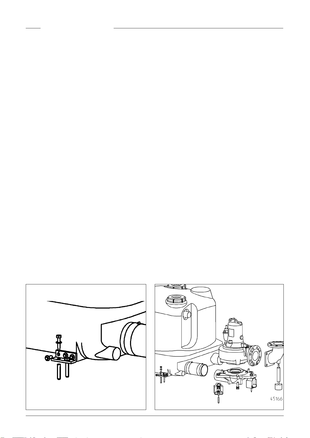
Screw the four angle brackets to the sides of the tank. NOTICE!
Ensure that the tank does not become deformed due to overtightening the screws, otherwise this could result in leakage.
Slide the lifting station, together with the clamping ange, as
far as possible onto the inlet pipe and then align them.
If a DN 150 side inlet is used, it must rst of all be opened up at
the location marked using a Ø 152 hole saw and then deburred.
The standard inlet must in this case be closed off with the sealing plug supplied.
Tighten the hexagon screws on the clamping ange.
In the case of compli 2500, connect the two tanks together
with a DN 150 pipe and clamping anges.
Mark the position of the drill-holes for anchoring the tank to
the ground, drill the holes, insert rawlplugs and screw the tank
in place using wood screws and washers.
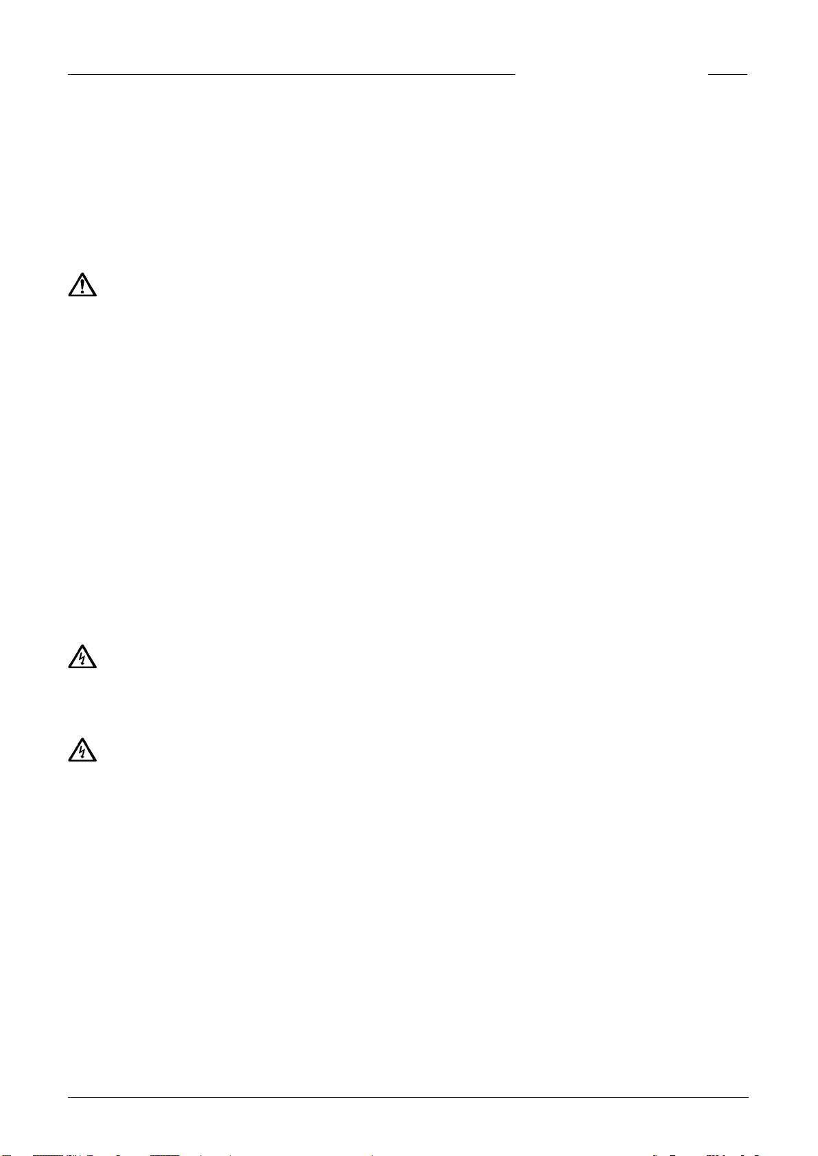
Installing the pump
Screw three duckfeet to the underside of each bend.
Connect the bends to the tank using a exible connector and
hose clamps.
Next, bolt the bends to the oor.
Place the seals on the bends, set the pumps down on top of
them and ax them from below using hexagon screws.
Installing the ventilation
Connect the DN 70 vent pipe to the top of the tank with the
exible connector and vent it above roof level. In the case of
compli 2500, both tanks must be connected with a exible
connector but they can be brought together with a tee branch.
Installing the pressure pipe
Attach the supports to the anged connections (accessory)
and screw them to the pumps. The remaining parts of the
pressure pipe can now be assembled:
1. Swing-type check valves (accessory),
2. Stop valves (accessory)
3. “Y” piece (accessory).
4. Connect up the pressure pipe with the exible connector and
a anged spigot (accessory) and take it in a loop over the local
backup level.
WARNING!
Before carrying out any work, unplug the lifting station from the
mains socket and ensure that the power supply to the lifting station cannot be switched on again by anyone else.
NOTICE!
water gets into the plug, this can cause malfunctions and damage.
The relevant standards (such as EN standards), national regulations (such as VDE in Germany), and the regulations of the local power supply companies must be observed.
Observe the operating voltage (see type plate)!
The lifting stations have a level controller that switches the
pumps on and off depending on the level of the water. An integrated alarm system beeps if there is a malfunction, even if
this is only temporary.
If the pumps overheat, the motor cuts out due to the winding thermostat. Before remedying the fault, the lifting station must be disconnected from the power supply. Unplug the
mains plug from the electrical socket or turn the main switch
off, as otherwise the pumps will be switched on again automatically after they have cooled down. A direct malfunction
message is not generated.
For the mains electrical connection of compli 1525, 1535, 2525
and 2535 type units, a correctly installed ve pole CEE power
socket is required (3/N/PEx400 V, 50 Hz). This must be located
in a dry room above the backup level.
For compli 1555, 1575, 15100, 2555 and 2575 type units, the
mains power supply is connected directly to the terminals of
the main switch for the control unit. The cross section of the
connection cable must be congured to take into account the
current input of the pumps and the length of the connection
cable.
NOTICE! Only time delay fuses or automatic fuses with C characteristics are to be used as pre-fuses for the pump. If the prefuses have been triggered, the cause of the malfunction must
be eliminated before switching the pump on again.
Never put the mains plug and free lead ends in water! If
Mounting the control unit
Only operate the control unit in dry rooms above the backup
level, and keep the housing closed at all times. The control
unit must be easily accessible to enable it to be checked at any
time. High humidity and condensation can destroy the controls!
Emergency pump connection (DN 50 at front)
This connection is used for the HMP hand diaphragm pump
(accessory).
Using a (Ø 38) hole saw, open up either the right-hand or lefthand pipe socket at the location marked and deburr the edges.
Fix the hand diaphragm pump to the wall at an easily accessible place and connect it to the pipe sockets on the tank with
PVC piping and exible connectors. The pressure pipe must be
laid in a loop above the local backup level.
ELECTRICAL CONNECTION
NOTICE! Only qualied electricians may carry out electrical
works to the pump or the control units.
Connecting the pumps
The pumps are connected to the control unit on site in accordance with the circuit diagram (appendix). The three-phase
pumps are protected with an overcurrent release or motor
protection switch, set to the rated current + 10%.
Coil thermostats
NOTICE! In addition to the overcurrent release or motor protection switch, the thermostats in the motor winding must be
connected to the control unit (terminal 30/32).
The thermostat contacts are suitable for a maximum of 250 V
/ 1.2 A (cos phi = 0.6) and are labelled 30 and 32 for connection
purposes. The motor is switched off via the 230V control circuit when the response temperature is reached. The pump is
switched on again automatically after the winding has cooled
down.
11
Page 12

ENGLISH
Connecting the level contact sensor
The level contact sensor is connected to the control unit on
site in accordance with the circuit diagram (appendix).
The switch-off point is set in the factory. The switch-on
point must be set for each individual lifting station. The other
switching points for the alarm (+2 cm) and peak load (+4 cm) are
then automatically set accordingly by the control unit.
Setting the switch-on level
Set the Hand-Off-Automatic selector to “0”. Adjust the switchon point in the “analogue evaluator” module on the right-hand
side of the control unit. Temporarily remove the transparent
cover of the module. Fill the collecting tank with water up to
the desired switch-on level (but not higher than the lower edge
of the inlet pipe).
There are three LEDs on the analogue evaluator labelled P1 P2 - P3. Only P2 must light up. If P3 lights up too, a readjustment must be carried out.
Turn the small setscrew below P1 one or two revolutions in a
clockwise direction. Now immerse the level controller oat in
the tank until it is below the switch-off point and then allow
it to oat up again. If P3 is still lit up, turn the setscrew a further revolution in a clockwise direction and immerse the oat
again.
Repeat this procedure until P3 no longer lights up, then turn
the setscrew back carefully in an anti-clockwise direction until
P3 only just lights up. The switch-on point is now set.
Alarm system
Malfunction messages are given both visually as well as acoustically. The standard mains-dependent alarm system indicates
motor faults in the pump (red LED). At the same time a built-in
acoustic alarm sounds. This acoustic signal can only be turned
off by remedying the fault or by totally deactivating it.
If an acoustic signal would be inappropriate at the installation
site in question, an alarm signal can be relayed via the potential-free contact (terminals 40 and 41) on the circuit board. The
connection cable must have maximum length of 250m for a
cross-section of 0.75 mm². The potential-free NO contact of
the centralised alarm can be loaded with a maximum of 5A /
250 VAC. The contact opens after the fault has been remedied.
CAUTION!
Only use the 9V-NiMh battery supplied by the manufacturer! If
dry-cell batteries or Lithium batteries are used there is a danger of explosion!
Time meter (accessory)
An optional time meter can be tted in the control unit. To t
this, shorten the connections of the time meter to approx. 8
mm and insert them in the four sockets at location A2 on the
printed circuit board. If the time meter indicator does not go
on after switching the lifting station on again, rotate the time
meter through 180°.
Shutting down the internal alarm buzzer
Remove the sealed jumper (BRX). To prevent the jumper from
getting lost, re-attach it to a pin on the two-pole pin connector.
External alarm buzzer
Open the transparent cover on the control unit.
An additional separate acoustic 12 VDC signal transmitter with
an input current of not more than 30 mA can be connected to
terminals “S+” and “S-”. The internal alarm buzzer can either be
switched on or off.
Test run and functional check
NOTICE! First of all tighten all clamps and anged connections.
1. Open the maintenance cover on the tank.
2. Open the sluice valves in the inlet pipe and pressure pipe.
3. Connect the lifting station to the power supply and observe
the indicator for the rotating eld direction.
4. Fill the tank up to the switch-on level.
5. The pump will now switch on and empty the tank. Observe
the pumping process through the maintenance opening.
6. Lift the oat of the level controller slowly by hand until it is
above the switch-on point and hold it there until the alarm
is triggered
7. Then close the maintenance opening with the cover and
seal.
8. Check to ensure that the tank, ttings and pipes are watertight, by carrying out several switching runs.
Battery pack for alarm system (accessory)
The alarm device is mains-dependent in its standard version,
i.e. it is not possible to trigger a high-water alarm in the event
of a power failure. To enable the alarm device to work even if
there is a power failure, a rechargeable battery must be used.
Open the transparent cover. Connect the battery to the connection clip, and use the existing cable tie to attach it to the
intended position on the PCB. The battery can supply the alarm
system with power for a continuous alarm of about 1 hour.
After the return of the mains voltage, the battery is charged
again automatically. An empty battery is ready for operation
within approx. 24 hours. It is fully charged after about 100
hours.
Check the function of the battery at regular intervals! To do so,
disconnect the lifting station from the mains power supply and
trigger a high-water alarm. The volume of the acoustic signal
must not become signicantly quieter over a period of several
minutes. The service life is about 5 years. Note the insertion
date on the battery, and after ve years the battery should be
replaced as a precautionary measure.
12
OPERATION
Automatic operation is the normal operating mode of the lifting station. The rocker switch must be set to “Automatic”. The
integrated level controller switches the pump on and off depending on the water level in the tank. A green LED lights up
when the pump is operating.
NOTICE! If unusually large quantities of wastewater ow into
the lifting station (e.g. when a pool is drained), partially close
the sluice valve at the inlet until the lifting station can operate normally again, switching on and off, (not pumping continuously, since this could overheat the pump motor).
Emergency operation with one pump
If maintenance valves are tted between the pump and the
tank, the lifting station can be temporarily operated with only
one pump.
Set the rocker switch for the faulty pump to “0” on the control
unit and close the maintenance valve.
Page 13
ENGLISH
Manual operation
Set the rocker switch to “Hand”. The pump will now operate in
continuous mode independently of the wastewater level. The
pumping out operation should therefore be observed through
the maintenance opening.
Shutting down
Set the rocker switch to “0”. This shuts down the pump. The
alarm system is still ready for use.
DANGER!
Do not use position “0” of the selector switch for repair and
maintenance work on the control unit and pump, but rather always unplug them from the mains or turn them off at the main
switch.
Inspection
To maintain operational reliability, carry out a visual inspection
of the lifting station, including the pipe connections, once a
month.
MAINTENANCE
Maintenance and inspection of this product must be carried
out in accordance with EN 12056-4.
To ensure continued reliability of service, we recommend that
you take out a service contract.
NOTICE! Servicing and maintenance of the sewage lifting sta-
tion as well as repair work must be carried out by a qualied
technician at intervals of 3 months in industrial plants or 6
months in blocks of ats.
WARNING!
Before carrying out any work, unplug the lifting station from the
mains power supply or turn it off at the main switch and ensure
that the power supply to the lifting station cannot be switched
on again by anyone else.
WARNING!
Check the plug and the mains cable for signs of mechanical
and chemical damage. Damaged or kinked cables must be replaced.
We recommend that the following work is included in the service:
1. Check the connection points for watertightness by inspect-
ing the areas surrounding the lifting station and the ttings.
2. Operate the sluice valves and check that they move easily.
Adjust and grease them if necessary.
3. Open and clean the swing-type check valve; check the seat
and ball (valve).
4. Clean the pump and the pipes where they connect to the
lifting station; check the impeller and the bearings.
5. Oil check. If necessary top up or carry out an oil change.
6. Clean the inside of the tank (as necessary, or if especially
required); remove any grease, for example.
7. Check the condition of the collecting tank.
8. Flush the system through with water once every 2 years.
9. Inspect the electrical section of the lifting station. The control unit itself is maintenance-free, but if a rechargeable
battery is tted, then it should be checked regularly to en-
sure that it is in good working order. To do so, unplug the
lifting station from the mains and lift the oat of the level
controller slowly by hand and hold it there until a high-water
alarm is triggered. In addition, clean the oat if necessary.
When all the maintenance tasks have been performed, carry
out a test run and then put the lifting station back into operation. The service must be documented, giving details of the
important data and of all the tasks carried out.
Oil check
First of all loosen the hexagon screws or Allen screws around
the pump and lift the pump off the duckfoot bend. The lling
and draining port of the oil reservoir is sealed off with a screwon drain plug labelled “Oil”. In order to check the mechanical
seal, the oil, including any residue, must be drained from the
oil reservoir and collected in a clean measuring container.
• If the oil is contaminated with water (milky), an oil change
must be carried out. Check again after a further 300 operating
hours, but at the very latest after 6 months!
• However, if the oil is contaminated with both water and pollutants, then not only the oil must be replaced, but the mechanical seal as well. For monitoring the oil reservoir, it is also
possible to retrot the electrode of our “DKG” seal leak control
device in place of the “DKG” screw plug.
Oil change
To ensure operational reliability, the rst oil change should be
carried out after 300 operating hours, with further oil changes
carried out after every 1000 operating hours. If the number of
operating hours is very low, an oil change should still be carried
out at least once a year.
If wastewater with strongly abrasive constituents is being
pumped, oil changes should be carried out at correspondingly
shorter intervals.
Use HLP hydraulic mineral oil, viscosity class 22 to 46, e.g.
Nuto from ESSO or DTE 22, DTE 24, or DTE 25 from Mobil, to
replace the oil in the oil reservoir.
The quantity of oil required is 1000 cm³ for ...C1 pumps and
1700 cm³ for ...B5, ...B6 and ...C5 pumps.
NOTICE! The oil reservoir must be lled with the specied
quantity of oil only. Overlling will result in the pump being ren-
dered inoperable.
QUICK TIPS FOR REMEDYING FAULTS
The lifting station does not work
• Check the mains voltage, the fuse and the FI circuit breaker.
Replace defective fuses only with fuses with the same nominal value. If the fuse triggers again, call a qualied electrician or our service engineers.
• The internal 2 A glass tube time delay fuse for the 230/12V
control transformer, the motor contactor and the 230V AC
power supply are faulty. Replace defective fuses only with
fuses of the same type and nominal value!
• If the mains cable is damaged, it must be replaced by the
manufacturer only.
• If the oat switch is obstructed, close the inlet sluice valve,
open the maintenance cover and clear the blockage.
13
Page 14

ENGLISH
Lifting station does not work and alarm is
triggered
• The thermostat in the motor windings has switched off the
system because the pump is obstructed. In this case, close
the inlet sluice valve, drain the tank, unplug the mains power
supply cable or switch off at the main switch, remove the
pump module, and clear the blockage
Decreased pumping performance
• Check that the sluice valve in the pressure pipe is fully open.
• If the pressure pipe is obstructed, ush water through the
pressure pipe to clear it.
• If the swing-type check valve is obstructed, close the sluice
valve and clean the swing-type check valve.
• If the ventilation system is blocked, clean the ventilation
hose between the pump and the tank and check the drilled
holes.
"Drehfeld falsch"
(Wrong rotating eld) indicator
is lit
• Mains phase sequence is wrong or phase is absent - thus
lower or absent pump delivery. The mains connection must
be corrected by a qualied electrician only.
"P2, P3 Pump failure" indicator is lit.
• The pump is protected by an integrated overload safety
switch which turns the pump off if it overloads or
is an electrical motor fault. After this has been triggered,
it must be reset by hand in order to use the pump again.
The control unit must be opened by a qualied electrician in
order to press the safety switch reset button.
if there
"P5 High water" indicator is lit
• Water level in the tank too high because of low pump ow
rate or excessive inow. Remove any obstructions in the
pump or pressure pipe and/or eliminate the excessive in-
ow.
LED P1 on the analogue evaluator is
continuously lit
• There is a fault in the level detection. Call our Customer ser-
vice.
• There is no residual water in the tank. Fill the tank with a
small amount of water.
• Note: If the LED lights up after the pumping operation, this
is not a sign of a malfunction. The LED goes off once the
tank is lled again with a small amount of wastewater.
Pump "snores" and does not switch itself off
• The switch-off point of the lifting station is too low.
Unscrew the three fastening screws of the level detection at
the front of the collecting tank. By carefully rotating it in an
anti-clockwise direction the switch-off point can be set to a
higher level. Retighten the screws. When the switch-off level
is reached during pumping, this is shown by the middle LED P2
on the analogue evaluator going off (on the right-hand side of
the control unit).
NOTICE! It may also be necessary to re-adjust the switch-on
level (please refer to the section “Redening the switch-on
level”).
14
Page 15

FRANÇAIS
Vous avez opté pour un produit Pentair Jung Pumpen, synonyme de qualité et de performance. Assurez-vous cette
performance par une installation conforme aux directives:
notre produit pourra ainsi remplir sa mission à votre entière
satisfaction. N‘oubliez pas que les dommages consécutifs à
un maniement non conforme porteront préjudice au droit à
la garantie.
Cet appareil peut être utilisé par des enfants d'au moins 8
ans ainsi que par les personnes ayant des capacités physiques, sensorielles ou mentales limitées ou qui manquent
d'expérience et de connaissance, dans la mesure où ils sont
surveillés ou s'ils ont reçu des instructions pour une utilisation en toute sécurité de l'appareil et qu'ils comprennent les
risques qui en résultent. Les enfants ne doivent pas jouer
avec l'appareil. Le nettoyage et l'entretien de l'appareil ne
doivent pas être effectués par des enfants si ceux-ci ne
sont pas sous surveillance.
Prévention des dommages en cas de défaillance
Comme tout autre appareil électrique, ce produit peut aussi
tomber en panne suite à une absence de tension ou à un défaut technique.
Si un dommage (également dommage consécutif) se produit
en raison de la défaillance du produit, les dispositions suivantes doivent être prise en particulier selon votre appréciation :
• Montage d’une alarme en fonction du niveau d’eau (éventu-
ellement aussi indépendante du réseau électrique) de sorte
que l’alarme puisse être perçue avant l’apparition d’un dommage.
• Contrôle de l’étanchéité du réservoir collecteur / cuve utili-
sée jusqu’au bord supérieur avant - toutefois au plus tard- le
montage ou la mise en service du produit.
• Montage de protection anti-retour pour les objets de draina-
ge sur lesquels un dommage peut survenir par l’écoulement
d’eau usée après une défaillance du produit.
• Montage d’un autre produit pouvant compenser la défail-
lance du produit (par ex. poste double).
• Montage d’un groupe de secours.
Étant donné que ces dispositions servent à prévenir ou réduire
les dommages consécutifs à une défaillance du produit, elles
sont obligatoires en tant que disposition du fabricant au même
titre que les contraintes normatives de la FR EN comme état
de la technique lors de l’utilisation du produit (OLG Francfort/
Main, n°dossier: 2 U 205/11, 15.06.2012).
CONSIGNES DE SÉCURITÉ
Ces instructions de service contiennent des informations essentielles à respecter lors de l‘installation, de la mise en service et de la maintenance.
Il est impératif que le monteur et l‘exploitant/ le personnel qualié concernés lisent les instructions de service avant le montage et la mise en service.
Les instructions doivent toujours être disponibles sur le lieu
d‘utilisation de la pompe ou de l‘installation.
Le non respect des consignes de sécurité peut entraîner la
perte de tous les droits à réparation du dommage.
Dans ces instructions de service, les consignes de sécurité
sont identiées de manière particulière par des symboles.
Risque d‘ordre général pour les personnes
Avertissement contre la tension électrique
AVIS! Danger pour la machine et le fonctionnement
Qualication du personnel
Le personnel pour le maniement, la maintenance, l‘inspection
et le montage doit posséder la qualication nécessaire à ce
type de travaux et il doit s‘être susamment bien informé par
une étude approfondie des instructions de service.
Domaine de responsabilité, l‘exploitant doit régler avec préci-
sion la compétence et le contrôle du personnel.
Si le personnel ne possède pas les connaissances nécessaires,
il est impératif de le former et de l‘instruire.
Travailler en étant soucieux de la sécurité
Il est impératif de respecter les consignes de sécurité, les règlements nationaux en vigueur concernant la prévention des
accidents et les prescriptions internes éventuelles de travail,
de service et de sécurité contenus dans ces instructions.
Consignes de sécurité pour l‘exploitant/ l‘utilisateur
Les directives légales, les règlements locaux et les directives
de sécurité doivent être respectés.
Il faut exclure les risques dus à l‘énergie électrique.
Les fuites de matières dangereuses à refouler (explosives,
toxiques ou brûlantes par exemple) doivent être évacuées de
telle sorte qu‘elles ne représentent aucun danger pour les personnes et l‘environnement. Les directives légales en vigueur
sont à respecter.
Consignes de sécurité pour le montage, les travaux d‘inspection et de maintenance
D‘une manière générale, les travaux à effectuer devront l‘être
exclusivement sur une machine à l‘arrêt. Les pompes ou agrégats refoulant des matières dangereuses pour la santé doivent
être décontaminés.
Directement après la n des travaux, tous les dispositifs de sécurité et de protection doivent être remis en place ou en ser-
vice. Leur ecacité est à contrôler avant la remise en service
et en tenant compte des directives et règlements en vigueur.
Transformation et fabrication de pièces détachées sans
concertation préalable
Une transformation ou une modication de la machine est
uniquement autorisée après consultation du fabricant. Les
pièces détachées d‘origine et les accessoires autorisés par
le fabricant servent à la sécurité. L‘utilisation d‘autres pièces
peut annuler la responsabilité quant aux conséquences en résultant.
Formes de service interdites
La sécurité d‘exploitation de la machine livrée est uniquement
garantie lors d‘une utilisation conforme. Il est absolument interdit de dépasser les valeurs limites indiquées au chapitre «
Caractéristiques technique «.
Consignes concernant la prévention des accidents
Avant les travaux de montage ou de maintenance, barrer la
zone de travail et contrôler le parfait état de l‘engin de levage.
Ne jamais travailler seul et utiliser un casque, des lunettes
protectrices et des chaussures de sécurité, ainsi qu‘en cas de
15
Page 16

FRANÇAIS
besoin, une ceinture de sécurité adaptée.
Avant d‘effectuer des soudures ou d‘utiliser des appareils élec-
triques, vériez l‘absence de risque d‘explosion.
Les personnes travaillant dans des infrastructures d‘assainissement doivent être vaccinées contre les agents pathogènes
pouvant éventuellement s‘y trouver. D‘autre part, veiller scrupuleusement à l‘hygiène, par égard pour votre santé.
Assurez-vous qu‘aucun gaz toxique ne se trouve dans la zone
de travail.
Respectez les règlements concernant la sécurité de travail et
gardez le nécessaire de premier secours à portée de main.
Dans certains cas, la pompe et le produit peuvent être brûlants, il y a alors risque de brûlure.
Des règles spéciales entrent en vigueur pour les installations
dans les secteurs à risque d‘explosion!
UTILISATION
Les postes de relevage pour matières fécales compli prêts à
brancher ont la certication LGA mode de construction et conviennent au relevage des eaux usées en provenance des toilettes et urinoirs ainsi que des eaux usées domestiques avec les
impuretés habituelles.
Les collecteurs sont submersibles avec une hauteur max. de 2
mCE et une durée de 7 jours au plus.
L’unité de commande n’est pas submersible mais est protégée
contre les projections d’eau selon IP44.
Pour une installation réglementaire et une utilisation conforme, l’unité de commande répond aux exigences de protection
de la norme EMC 2014/30/EU et convient à une intervention en
habitat individuel avec une connexion sur le réseau électrique
public. En cas de branchement à un réseau industriel au sein d'
une exploitation industrielle avec une alimentation électrique
en provenance d'un propre transformateur haute tension, il
faut s'attendre, entre-autres, à une résistance des perturba-
tions insusante.
Lors de l'utilisation des postes, il est nécessaire d'observer les
différentes lois nationales, les directives ainsi que les dispositions locales, comme par ex.
• Les postes de relevage des eaux usées pour l'assainissement
des terrains et des bâtiments (par ex. en Europe EN 12050 et
12056)
• La réalisation d'installations à basse tension (par ex. en Alle-
magne VDE 0100)
• Sécurité et équipement (par ex. en Allemagne la réglemen-
tation sur la sécurité dans les entreprises "BetrSichV" et BGR
500)
• Sécurité dans les postes de technique d'eaux usées ( par ex.
en Allemagne GUV- V C5, GUV-R 104, GUV-R 126)
• Installations électriques et matériel (par ex. en Allemagne
GUV-V A3)
• Protection antidéagrante EN 60079- 0, EN 60079-1, EN
60079- 14, EN 60079-17 et EN 1127-1
Contenu de la livraison
• un ou deux collecteurs avec bride de serrage DN 150 pour
l'amenée
• deux pompes pour eaux usées
• coude à patins pour les pompes
• jonction(s) élastique(s) avec colliers pour le conduit
d’aération DN 70
• jonctions élastiques avec colliers pour coudes à patins
• jonction élastique avec colliers pour la conduite de refoule-
ment
• matériel de xation pour le collecteur et les coudes à patins
• unité de commande
Mode de fonctionnement : service discontinu S3,
cf. caractéristiques techniques
MONTAGE
Le poste de relevage doit être monté avec une protection contre les poussées verticales ainsi qu'en pose libre. Il est nécessaire de prévoir un espace de travail de 60 cm min. en largeur
et en hauteur autour et au-dessus de toutes les pièces à utiliser et à entretenir.
16
Page 17

FRANÇAIS
Aération : le conduit d'aération doit être dirigé au-dessus du
niveau du toit.
Amenée : il faut placer dans l'amenée une vanne d’arrêt avant
le collecteur.
Il est nécessaire de monter une vanne de maintenance entre
chaque pompe et le collecteur an de pouvoir continuer à utiliser le poste en cas de dysfonctionnement ou de maintenance
d’une pompe.
Conduite de refoulement : il faut placer une autre vanne pour
eaux usées dans la conduite de refoulement derrière un clapet
anti-retour certié EN. La conduite de refoulement doit être
dirigée avec une boucle au-dessus du niveau de retenue xé
localement.
Il faut prévoir un puisard de pompe pour l'assainissement du
local d'installation.
Les postes de relevage pour matières fécales compli 1500 et
compli 2500 sont livrés en modules de construction et sont
montés sur place par une entreprise d’installation.
AVIS ! Toutes les vis qui servent à xer les différentes pièces
sur le collecteur doivent uniquement être serrées avec un
couple de serrage max. de 6 Nm.
Montage du collecteur
Fermer la vanne dans l'amenée (accessoire) an d'empêcher
une intrusion d'eau pendant le montage.
Visser les quatre équerres de xation de façon latérale sur le
collecteur. AVIS! Ne pas serrer les vis trop fortement pour ne
pas déformer le collecteur. Il y a sinon un risque de fuites.
Pousser le poste de relevage avec la bride de serrage contre la
butée sur le tuyau d'amenée et ajuster.
En cas d’utilisation d’une entrée latérale DN 150, cette entrée
doit d’abord être ouverte à l’endroit marqué au moyen d’une
scie-cloche Ø 152 et ébavurée ensuite. L’entrée standard doit
alors être obturée au moyen du bouchon d’obturation fourni.
Bien serrer les vis à six pans de la bride de serrage.
Pour les compli 2500, relier maintenant les deux collecteurs
ensemble avec un tuyau DN 150 et les brides de serrage.
Marquer des trous pour la xation au sol du collecteur et percer, insérer la cheville et xer le collecteur avec les vis à bois
et les rondelles.
Montage des pompes
Trois patins sont vissés sous chaque coude.
Les coudes sont ensuite reliés au collecteur via une jonction
élastique et les colliers de serrage.
La prochaine étape consiste à cheviller les coudes au sol.
Les joints d’étanchéité sont alors posés sur les coudes, les pom-
pes sont mises en place et xées par le bas à l’aide des vis six pans.
Montage de l’aération
Le conduit d’aération DN 70 est raccordé à l’aide d’une jonction
élastique en haut sur le collecteur et est dirigé au-dessus du
niveau du toit. Pour les compli 2500, il est nécessaire d’équiper
les deux collecteurs d’un conduit d’aération, ces derniers pouvant néanmoins être dirigés ensemble à l’aide d’une pièce en T.
Montage de la conduite de refoulement
Équiper les raccords à bride (accessoires) de supports et les
visser aux pompes. La conduite de refoulement est maintenant
réalisée :
1. Clapets anti-retour (accessoires),
2. Vannes d’arrêt (accessoires),
3. Adaptateur en Y (accessoires).
4. Connecter la conduite de refoulement avec la jonction élastique et la bride à emboîtement (accessoires) et la diriger audessus du niveau de retenue local avec une boucle.
Raccord de l’évacuation de secours (DN 50 à
l’avant)
Ce raccord est utilisé pour la pompe manuelle à diaphragme
HMP (accessoire).
Percer l’embout au choix à droite ou à gauche au niveau du
marquage à l’aide d’une scie-cloche (Ø 38) et ébavurer.
Fixer la pompe manuelle à diaphragme au mur de façon à ce
qu’elle soit bien accessible et la raccorder à la tubulure du collecteur avec le tuyau PVC et la jonction élastique (accessoires).
La conduite de refoulement doit être dirigée avec une boucle
au-dessus du niveau de retenue local.
BRANCHEMENT ÉLECTRIQUE
AVIS ! Seul un électricien spécialisé est autorisé à effectuer
les travaux électriques sur la pompe, la che ou l’unité de commande.
AVERTISSEMENT !
Avant chaque intervention, retirer la che secteur du poste et
s’assurer que le poste ne peut pas être remis sous tension par
d’autres personnes.
AVIS!
Ne jamais mettre la che secteur et les extrémités de câb-
le libres dans l’eau ! L'eau qui est susceptible de s'inltrer peut
causer des défaillances et des endommagements.
Il est nécessaire de tenir compte, à chaque fois, des normes
en vigueur (par ex. EN), des directives spéciques au pays (par
ex. VDE) ainsi que des directives de l'opérateur local du réseau
d'alimentation.
Observer la tension de service (cf. plaque signalétique) !
Les postes disposent d'un commutateur de niveau qui enclen-
che ou stoppe les pompes en fonction du niveau d'eau. Le bip
du dispositif d'alarme intégré indique la présence d'un dysfonctionnement même si celui-ci n’est que temporaire.
Si les pompes sont devenues trop chaudes, elles sont interrompues par les thermostats à enroulement. Avant d'éliminer
le problème, il est nécessaire de mettre le poste hors tensi-
on. Pour ce faire, débrancher la che secteur ou désactiver
l’interrupteur principal car autrement les pompes se remettraient en marche automatiquement après avoir refroidi. Un signal
de panne direct n’a pas lieu.
En ce qui concerne les compli 1525, 1535, 2525 et 2535 , le branchement secteur du poste (3/N/PEx400 V, 50 Hz) se fait avec
une prise de courant CEE à 5 pôles installée de façon réglementaire et se trouvant dans une pièce au sec au-dessus du
niveau de retenue.
En ce qui concerne les compli 1555, 1575, 15100, 2555 et 2575,
le branchement secteur (3/N/PEx400 V, 50 Hz) se fait directement sur les bornes de l’interrupteur principal de l’unité de
commande. La section de câble doit être dimensionnée en
fonction de la consommation de courant des pompes et de la
longueur de câble.
AVIS! Il faut uniquement utiliser des fusibles à action retardée
17
Page 18

FRANÇAIS
ou des disjoncteurs de type C en tant que fusibles de puissance (se référer au schéma de connexion pour la taille). Si les
fusibles de puissance se sont déclenchés, il faut éliminer le
problème avant de remettre le poste sous tension.
Montage de l’unité de commande
Faire fonctionner l'unité de commande uniquement dans des
endroits secs au-dessus du niveau de retenue et garder le boîtier toujours fermé. L'unité de commande doit être facilement
accessible an qu'il soit possible d'effectuer un contrôle à tout
moment. Une humidité de l'air élevée ainsi que la buée peuvent
endommager l'unité de commande.
Raccordement des pompes
Les pompes sont raccordées sur place à l’unité de commande
conformément au schéma de connexion (annexe). Les pompes
à courant triphasé sont protégées par un déclencheur à maximum de courant ou par un disjoncteur-protecteur, réglage sur
le courant nominal + 10 %.
Thermostats à enroulement
AVIS! Outre le déclencheur à maximum de courant ou le dis-
joncteur-protecteur, il est nécessaire de raccorder les thermostats intégrés à l’enroulement du moteur à l’unité de commande (borne 30/32).
Les contacts des thermostats sont conçus pour max. 250V/1,2
A (cos phi 0,6) et portent les désignations 30 et 32 en ce qui
concerne le raccordement. Lorsque la température de déclenchement est atteinte, le moteur est désactivé via le circuit
de commande 230 V. La pompe se remet automatiquement en
marche une fois l’enroulement refroidi.
Branchement de l’indicateur de niveau
L’indicateur de niveau est raccordé sur place à l’unité de commande conformément au schéma de connexion (annexe).
Le point d’arrêt est réglé en usine. Le point d’enclenchement
doit être réglé à titre individuel pour chaque poste. Les autres
points de commutation pour l'alarme (+ 2 cm) et pour la charge
de pointe (+ 4 cm) sont alors ajustés en conséquence par l'unité
de commande de façon automatique.
Fixer le niveau d’enclenchement
Mettre l’interrupteur Manuel-0-Automatique sur « 0 ». L’ajustage
du point d’enclenchement est effectué dans le module « contrôle
analogue », à droite sur le côté dans l’unité de commande. Enlever temporairement le couvercle transparent du module. Remplir le réservoir collecteur d’eau jusqu’au niveau d’enclenchement
souhaité (au maximum jusqu’au bord inférieur de l’entrée).
Sur le module de contrôle analogue se trouvent trois diodes
portant les désignations P1 - P2 - P3. Seule P2 doit être allumée
; si P3 est également allumée, il faut procéder à un réajustage :
Tourner la petite vis de réglage, qui se trouve au-dessous de
P1, d’un à deux tours dans le sens horaire. Plonger maintenant
le otteur dans le réservoir sous le point d’arrêt et laisser le
remonter ensuite. Si P3 est toujours allumée, tourner la vis de
réglage d’un nouveau tour dans le sens horaire et plonger le
otteur une nouvelle fois.
Refaire cette opération jusqu’à ce que P3 ne soit plus allumée,
tournez ensuite la vis de réglage avec précaution dans le sens
horaire inverse jusqu’à ce que P3 s’allume de nouveau. Le point
d’enclenchement est déni.
Dispositif d’alarme
Les signaux de panne ont lieu aussi bien de façon visuelle que
sonore. Le dispositif d'alarme standard dépendant du réseau
signale les pannes de moteur de la pompe (diode rouge). En
même temps, une alarme sonore intégrée retentit. Il est possible d'arrêter ce signal sonore de façon générale ou uniquement
en éliminant le problème.
Si le lieu de montage ne permet pas la présence d'un contrôle sonore de la panne, il est possible de transmettre le signal
d'alarme via le contact libre de potentiel ou « sec » (bornes
40 et 41) sur la platine. Le câble de raccordement ne doit pas
dépasser 250 m de long, avec une section de 0,75 mm². Le
contact à fermeture du dysfonctionnement général supporte
une charge max. de 5A / 250 V AC. Le contact s'ouvre après
l'élimination de la panne.
Accumulateur pour le dispositif d’alarme
(accessoire)
Le dispositif d'alarme standard est dépendant du réseau, c.-àd. dans le cas d'une panne de courant, l'alarme de niveau trop
haut ne peut pas se déclencher. An que le dispositif d'alarme
continue également de fonctionner en cas d'une panne de
courant, il est nécessaire d'utiliser un accumulateur. Ouvrir la
porte transparente. Connecter l'accumulateur au clip de rac-
cordement et le xer sur la platine à l’emplacement prévu avec
l'attache de câbles présente. Celui-ci peut alimenter le dispositif d'alarme en électricité pour une alarme d'une durée d'env.
1 heure.
Après le retour de la tension du réseau, l'accumulateur se recharge automatiquement. Un accumulateur déchargé est prêt
à fonctionner après env. 24 heures, une recharge complète est
atteinte après 100 heures env.
Vérier régulièrement le bon fonctionnement de l'accumulateur
! Pour cela, débrancher la tension électrique et déclencher un
signal de niveau trop haut des eaux. Le volume de l'alarme sonore ne doit pas diminuer de façon importante pendant quelques minutes. La durée de vie est d'env. 5 ans. Noter la date
de mise en place sur l'accumulateur et changer celui-ci à titre
préventif au bout de 5 ans.
ATTENTION !
Utiliser seulement l'accumulateur 9V-NiMh du fabricant ! Il
existe un risque d'explosions avec l'utilisation de piles sèches ou
l'accumulateur Lithium !
Compteur horaire
Il est possible d'intégrer de façon optionnelle un compteur horaire dans l'unité de commande. Pour cela, réduire les raccor-
dements du compteur horaire à env. 8 mm et les encher dans
les 4 connecteurs femelles à l’emplacement A2 sur la platine. Si
rien ne s'ache après une nouvelle mise en service du poste,
le compteur horaire doit être tourné de 180°.
Arrêter le vibreur sonore externe
Retirer le cavalier scellé (BRX). Pour que la che ne se perde
pas, encher à nouveau le cavalier sur une broche de la bar-
rette à 2 pôles.
Vibreur sonore externe
Ouvrir la porte transparente de l'unité de commande.
Un transmetteur sonore de signaux 12 VDC supplémentaire et
isolé peut être raccordé aux bornes « S+ » et « S- » avec une
18
Page 19

FRANÇAIS
intensité absorbée max. de 30 mA. Le vibreur d'alarme interne
peut être au choix activé ou désactivé.
Marche d’essai et contrôle du
fonctionnement
AVIS! Tout d’abord, bien serrer tous les colliers et les raccords
à bride.
1. Ouvrir le couvercle de nettoyage sur le collecteur.
2. Ouvrir la vanne dans la conduite d'amenée et la conduite de
refoulement.
3. Mettre le poste sous tension, observer l'indication du sens
de rotation du champ.
4. Remplir le collecteur jusqu'au niveau d'enclenchement.
5. La pompe s'active maintenant et vide le collecteur. Obser-
ver le pompage par l'orice de nettoyage.
6. Soulever lentement ainsi que manuellement le otteur de commutation de niveau au-dessus du point
d'enclenchement jusqu'à ce que le dispositif d'alarme se
déclenche.
7. Fermer à nouveau l'orice de nettoyage avec le couvercle et
le joint d'étanchéité.
8. A l'aide de plusieurs cycles de manœuvres, vérier
l'étanchéité du collecteur, des armatures et de la tuyauterie.
FONCTIONNEMENT
Le fonctionnement automatique est le mode de fonctionnement normal du poste. Pour cela, il faut placer l'interrupteur à
bascule dans la position « automatique ». Grâce au commutateur de niveau intégré, la pompe est activée ou désactivée en
fonction du niveau d'eau dans le collecteur. Le fonctionnement
de la pompe est aché via une diode lumineuse verte.
AVIS ! En cas d'un débit exceptionnellement important (par
ex. assainissement d'une piscine), il faut réduire la vanne dans
l’amenée autant que possible an que le poste de relevage
continue à travailler en mode normal (pas de fonctionnement
continu car le moteur de la pompe pourrait autrement être en
surchauffe).
Fonctionnement de secours avec une pompe
Si des vannes de maintenance sont montées entre la pompe
et le collecteur, il est possible de faire fonctionner temporairement le poste avec une seule pompe.
La pompe défectueuse est mise en position « 0 » sur l’unité
de commande à l’aide de l’interrupteur à bascule et la vanne de
maintenance est fermée.
Mode manuel
Placer l’interrupteur à bascule dans la position « manuelle ». La
pompe travaille maintenant en fonctionnement continu indépendamment du niveau des eaux usées. C'est pourquoi, il est
nécessaire de surveiller le pompage via l'orice de nettoyage.
Arrêt
Mettre l'interrupteur à bascule dans la position "0", la pompe
est maintenant arrêtée. Le dispositif d'alarme continue de fonctionner.
toujours retirer la che secteur de la prise de courant ou désactiver l’interrupteur principal.
Inspection
An de maintenir la sécurité de fonctionnement, il est nécessaire de prévoir un contrôle visuel du poste ainsi que des jonctions de tuyaux une fois par mois.
MAINTENANCE
L'entretien et le contrôle de ce produit doivent être effectués
conformément à la norme EN 12056-4. An d'assurer une sé-
curité de fonctionnement durable de votre poste, nous vous
recommandons de conclure un contrat de maintenance.
AVIS ! La maintenance du poste de relevage pour matières
fécales et les mesures d'entretien doivent être réalisées par
des personnes compétentes à intervalles de 3 mois dans les
exploitations industrielles ou de 6 mois dans les habitations
collectives.
AVERTISSEMENT !
Avant chaque intervention, retirer la che secteur du poste ou
désactiver l’interrupteur principal et s’assurer que le poste ne
peut pas être remis sous tension par d’autres personnes.
AVERTISSEMENT !
Vérier la présence d’éventuels dommages mécaniques et
chimiques sur la che et le câble secteur. Il est nécessaire de
remplacer les câbles endommagés ou pliés.
Lors de la maintenance, nous recommandons de procéder aux
travaux suivants :
1. Vériez l'étanchéité des zones de connexion en observant
les alentours des postes et des armatures.
2. Activer la vanne, contrôler son bon déplacement, réajuster
et graisser si besoin est.
3. Ouvrir et nettoyer le clapet de retenue ; contrôle de l’assise
et de la bille (clapet).
4. Nettoyage de la pompe et de la zone de la conduite directement connectée ; contrôle de la roue à aubes et du palier.
5. Contrôle de l'huile, compléter si nécessaire ou changer
l'huile.
6. Nettoyage intérieur du collecteur (si besoin est ou après
des exigences particulières) par ex. enlever la graisse.
7. Contrôler l'état du réservoir collecteur.
8. Rincer le poste avec de l’eau tous les 2 ans.
9. Contrôler la partie électrique du poste. L'unité de commande même ne nécessite pas de maintenance mais si un
accumulateur a été intégré, il est nécessaire de contrôler
régulièrement sa capacité de fonctionnement. Pour ce fai-
re, soulever le otteur du collecteur avec un poste mis hors
tension jusqu'à ce que l'alarme indiquant un niveau haut des
eaux retentit. En outre, le otteur doit être nettoyé si besoin
est.
Après avoir effectué les travaux de maintenance, l'installation
est à mettre en service après une marche d'essai. Il est nécessaire de réaliser un rapport concernant la maintenance en
indiquant tous les travaux effectués ainsi que les données importantes.
DANGER !
Ne pas utiliser la position « 0 » pour les travaux de réparation
ou de maintenance sur l'unité de commande ou la pompe mais
Contrôle de l’huile
Dévisser tout d'abord les vis à six pans et les vis à six pans
19
Page 20

FRANÇAIS
creux tout autour de la pompe et retirer la pompe du coude à
patins. L'orice de remplissage et de purge de la chambre à
huile a une vis de fermeture « huile » qui assure l'étanchéité
vers l'extérieur. An de contrôler la garniture mécanique
d'étanchéité, l'huile de la chambre à huile, y compris la quantité
résiduelle, est vidée et recueillie dans un gobelet de mesure
propre.
• Si l'huile est chargée d'eau (aspect laiteux), il est nécessaire
de la changer. Contrôler à nouveau après 300 heures de fonctionnement, mais au maximum au bout de 6 mois !
• Si cependant l'huile est chargée d'eau et d'impuretés, il est
nécessaire de changer également la garniture mécanique
d'étanchéité en plus de l'huile. Pour le contrôle de la chambre à huile, il est possible de monter, aussi ultérieurement,
l'électrode de notre appareil de contrôle d'étanchéité « DKG » à
la place de la vis de fermeture « DKG ».
Changement de l'huile
Pour un maintien de la sécurité de fonctionnement, il est nécessaire de réaliser un premier changement d'huile après 300
heures de fonctionnement et les autres changements d'huile
au bout de 1000 heures de fonctionnement à chaque fois. En
cas d'un nombre plus faible d'heures de fonctionnement, il est
nécessaire d'effectuer un changement d'huile au moins une
fois par an.
Si la pompe refoule des eaux usées avec des impuretés très
abrasives, il est nécessaire de prévoir les changements d'huile
à des intervalles plus courts.
Pour le changement du contenu de la chambre à huile, il est
nécessaire d'utiliser une huile minérale pour hydraulique HLP
avec une viscosité de 22 à 46 comme par exemple Nuto de
chez ESSO ou DTE 22, DTE 24, DTE 25 de chez Mobil.
La quantité de remplissage est de 1000 cm³ pour les pompes
...C1 et de 1700 cm³ pour les pompes ...B5, ...B6 et ...C5.
AVIS!
La chambre à huile doit uniquement être remplie avec la
quantité indiquée. Si elle est trop remplie, cela risque de détruire la pompe.
QUELQUES
CONSEILS EN CAS DE DYSFONCTIONNEMENTS
Le poste ne fonctionne pas.
• Vérier la tension secteur, le fusible et le disjoncteur diffé-
rentiel. Remplacer les fusibles défectueux uniquement par
des fusibles de même valeur nominale. En cas d'un nouveau
déclenchement, appeler un électricien ou le service aprèsvente.
• Le fusible interne en verre 2 A avec action retardée pour
le transformateur de commande 230/12 V, le contacteur de
moteur et l'alimentation de courant monophasé 230 V sont
défectueux. Un fusible défectueux ne doit être remplacé que
par le même type et la même valeur.
• Câble d’alimentation
uniquement par le fabricant
• Interrupteur à otteur bloqué = fermer la vanne
vrir le couvercle de nettoyage et remédier au blocage.
Le poste ne fonctionne pas, signal d’alarme
• Le thermostat à enroulement du moteur a désactivé la pom-
pe car cette dernière est bloquée = fermer la vanne d'entrée,
endommagé, remplacement effectué
d'entrée, ou-
vider le collecteur, retirer la che secteur ou désactiver
l’interrupteur principal, démonter la garniture de la pompe et
remédier au blocage.
Débit diminué
• La vanne
fait ouverte
• Conduite de refoulement obstruée = rincer la conduite de
refoulement
• Clapet anti-retour obstrué = fermer la vanne et nettoyer le
clapet anti-retour
• Aération de la pompe obstruée = nettoyer le tuyau d'aération
pompe-collecteur et contrôler les perçages.
L’achage indique "Drehfeld falsch" (Rotation du champ
incorrecte)
• Ordre incorrect des phases
quoi le refoulement de la pompe est faible ou inexistant =
Correction du branchement réseau
tricien.
L’achage indique « Störung Pumpen » (Défaillance
pompe)
• Pour protéger la pompe, un interrupteur de protection contre
les surintensités de courant est présent et désactive la pompe
en cas de surcharge ou d'une erreur électrique du moteur. An
de remettre la pompe en marche après le déclenchement de
l'interrupteur, celui-ci doit être réinitialisé de façon manuelle.
L'unité de commande doit être ouverte par un électricien
an d'activer le bouton de réinitialisation.
L’achage indique « Hochwasser » (Niveau trop haut des
eaux usées)
• Le niveau d'eau dans le collecteur est trop haut en raison d'un
refoulement insusant ou d'une arrivée abondante = Enlever
les éventuelles obstructions dans la pompe ou la conduite de
refoulement ou remédier à une arrivée abondante.
La diode P1 sur le module de contrôle analogue s'allume en
continu
• Il y a une défaillance
vice après-vente
• Il n'y a pas d'eau résiduelle dans le collecteur = ajouter un peu
d'eau
• Remarque : un court éclairage après le pompage n'indique
pas un problème de fonctionnement. L’achage s’éteint
que les eaux usées arrivent.
La pompe fait du bruit et ne s’arrête pas
• Le point d’arrêt du poste est trop bas =
de xation du détecteur de niveau à l'avant sur le réservoir
collecteur. En tournant prudemment dans le sens inverse des aiguilles d’une montre, vous pouvez placer le point
d'arrêt plus haut. Resserrer ensuite les vis de xation. La
diode centrale P2 du module de contrôle analogue s'éteint
lorsque le niveau d'arrêt est atteint lors du pompage (à droite
sur le côté dans l’unité de commande).
AVIS! Le niveau d'enclenchement doit maintenant éventuelle-
ment être de nouveau ajusté (cf. « Régler à nouveau le niveau
d'enclenchement »).
dans la conduite de refoulement n'est pas tout à
ou phase manquante, c'est pour-
uniquement par un élec-
du détecteur de niveau = appeler le ser-
dès
Enlever les trois vis
20
Page 21

NEDERLANDS
U hebt een product van Pentair Jung Pumpen gekocht en
daarmee kwaliteit en vermogen aangeschaft. Zorg dat dit
vermogen tot zn recht komt door een installatie volgens
de voorschriften, zodat ons product zn taak tot volle tev-
redenheid kan uitvoeren. Denk eraan dat schade als gevolg
van oneigenlk gebruik van invloed kan zn op de garantie.
Dit toestel kan door kinderen van 8 jaar en ouder alsook door
personen met verminderde fysische, sensorische of mentale vaardigheden of gebrek aan ervaring en kennis gebruikt
worden, wanneer hierop toegezien wordt of indien z onderricht werden over het veilige gebruik van het toestel en z de
hieruit resulterende gevaren verstaan. Kinderen mogen niet
met het toestel spelen. Reiniging en gebruiksonderhoud mogen niet door kinderen zonder toezicht uitgevoerd worden.
Schadepreventie b uitval
Zoals elk ander elektrisch apparaat kan ook dit product door ontbrekende netspanning of een technisch mankement uitvallen.
Als u door het uitvallen van het product schade (met inbegrip
van gevolgschade) kunt oplopen, moet u in het bzonder de
volgende voorzorgsmaatregelen treffen:
• Installatie van een waterpeilafhankelk (onder bepaalde
omstandigheden ook ktriciteitsnetonafhankelk) alarmsysteem, zodat het alarm nog vóór het optreden van de schade
kan worden waargenomen.
• Controle van het gebruikte verzamelreservoir/de schacht
tot aan de bovenrand op lekkage voorafgaande aan -uiterlk
echter tdens- de installatie of ingebruikname van het pro-
duct.
• Installatie van terugstuwbeveiligingen voor afwateringsob-
jecten die na uitval van het product door vrkomend afvalwater beschadigd kunnen raken.
• Installatie van een ander product dat het uitvallen van het
product kan opvangen (bv. een dubbel systeem).
• Installatie van een noodstroomaggregaat.
Aangezien deze voorzorgsmaatregelen ertoe dienen om gevolgschade te voorkomen of tot een minimum te beperken als
het product uitvalt, moeten ze als richtln van de fabrikant analoog aan de normatieve specicaties van DIN EN als stand
van de techniek - verplicht in acht worden genomen b het
gebruik van het product (OLG Frankfurt/Main, Az. (reg.nr.): 2 U
205/11, 15.06.2012).
VEILIGHEIDSTIPS
Deze handleiding bevat basisinformatie die b installatie, bediening en onderhoud in acht moet worden genomen. Het is
belangrk ervoor te zorgen dat deze handleiding voorafgaande aan de installatie en ingebruikname door de monteur en
het verantwoordelke personeel/eigenaar wordt gelezen. De
handleiding moet steeds beschikbaar zn op de plaats waar de
pomp of de installatie zich bevindt.
B het niet opvolgen van de veiligheidsinstructies kan de aan-
spraak op schadervergoeding vervallen.
In deze handleiding zn de veiligheidsinstructie extra aangegeven met symbolen. Het niet opvolgen kan tot gevaarlke si-
tuaties leiden.
Algemeen gevaar voor personen
Waarschuwing voor elektrische spanning
LET OP! Gevaar voor machine en functioneren
Personeelskwalicatie
Het personeel voor bediening, onderhoud, inspectie en monta-
ge moet gekwaliceerd zn voor dit werk en zichzelf door een
grondige bestudering van de handleiding voldoende geïnfor-
meerd. Verantwoordelkheidsgebied, competentie en toezicht
op het personeel moeten goed geregeld door de eigenaar. Als
het personeel niet over de nodige kennis beschikt, dan moet
het worden opgeleid en geïnstrueerd.
Veilig werken
De veiligheidsinstructies in deze gebruikshandleiding, de bestaande nationale regelgeving voor de preventie van ongevallen, evenals interne arbeids-, gebruiks- en veiligheidsvoorschriften moeten in acht worden genomen.
Veiligheidsinstructies voor de gebruiker/eigenaar
Er moet worden voldaan aan wettelke eisen, lokale regelgeving en veiligheidseisen.
Risico's door elektrische energie moeten worden uitgesloten.
Gemorste gevaarlke afvoerproducten (bv. explosief, giftig,
heet) moet zodanig worden verwderd dat er geen gevaar optreedt voor mens en milieu. De wettelke bepalingen moeten in
acht worden genomen.
Veiligheidsinstructies voor montage, inspectie en onderhoudswerkzaamheden
In principe moeten werkzaamheden aan de machine alleen wor-
den uitgevoerd b stilstand. Pompen of aggregaten die stoffen
afvoeren die gevaarlk zn voor de gezondheid, moeten worden
ontsmet.
Onmiddellk na de voltooiing van de werkzaamheden moeten
alle veiligheids- en beschermingsvoorzieningen weer worden
geïnstalleerd of in werking gezet. Hun functioneren moet voorafgaande aan de ingebruikname worden gecontroleerd conform de geldende regels en voorschriften.
Eigenmachtige modicaties en vervaardiging van onderdelen
Wziging of aanpassing van de machine is alleen toegestaan na
overleg met de fabrikant. Originele reserveonderdelen en ac-
cessoires door de fabrikant zn er voor de veiligheid. Het gebruik van andere onderdelen kan de aansprakelkheid voor de
gevolgen daarvan teniet doen.
Oneigenlk gebruik
De betrouwbaarheid van de geleverde machine wordt alleen
gegarandeerd b juist gebruik. De aangegeven grenswaarden
in het hoofdstuk "Technische gegevens" mogen in geen enkel
geval worden overschreden.
Aanwzingen voor het voorkomen van ongevallen
Voorafgaande aan montage- of onderhoudswerkzaamheden
zet u de werkruimte af en controleert u het hstoestel op onberispelke werking.
Werk nooit alleen en gebruik een helm, een veiligheidsbril en
veiligheidsschoenen en indien nodig een geschikt veiligheidsharnas.
Voordat u gaat lassen of elektrische apparatuur gaat gebruiken, moet u controleren of er geen explosiegevaar bestaat.
Wanneer mensen in afvalwaterinstallaties werken, moeten z
worden ingeënt tegen mogelk daar aanwezige ziektekiemen.
Let vanwege uw gezondheid ook heel goed op de hygiëne.
21
Page 22

NEDERLANDS
Zorg ervoor dat er geen giftige gassen in de werkruimte aan-
wezig zn.
Neem de regels van de arbeidsinspectie in acht en zorg dat er
eerste-hulpmateriaal beschikbaar is.
In sommige gevallen kunnen pompen en het af te voeren mate-
riaal heet zn, dan bestaat er kans op verbranding.
Voor installatie in explosiegevaarlke gedeeltes zn bzondere
voorschriften van toepassing!
TOEPASSING
De compli-fecaliënopvoerinstallaties zn LGA-goedgekeurd
en geschikt voor het opvoeren van afvalwater uit toiletten en
urinoirs, evenals van huishoudelk afvalwater met de gebruikelke toevoegingen.
De reservoirs zn dompelbaar met een max. hoogte van 2 m
waterkolom (WK) en een duur van maximaal 7 dagen.
De besturing is niet dompelbaar, maar spatwaterdicht conform
IP 44.
B correcte installatie en beoogde gebruik voldoet de besturing aan de veiligheidseisen van de EMC-richtln 2014/30/EU
en is geschikt voor gebruik in huis met aansluiting op het open-
bare elektriciteitsnet. B aansluiting op een industrieel elektriciteitsnet binnen een industrieel bedrf met een stroom-
voorziening door een eigen hoogspanningtransformator, moet
onder omstandigheden met onvoldoende immuniteit rekening
worden gehouden.
B het gebruik van de apparatuur moeten de relevante nationale wettelke en lokale voorschriften worden nageleefd, zoals
bv.
• Pompinstallaties voor afvalwater van gebouwen en terreinen
(bv. in Europa EN 12050 en EN 12056)
• Opbouw van laagspannings-elektrische installaties (bv. in
Duitsland VDE 0100)
• Veiligheid en arbeidsmiddelen (bv. in Duitsland BetrSichV
en BGR 500)
• Veiligheid in afvalwaterinstallaties (bv. in Duitsland GUV-V
C5, GUV-R 104, GUV-R 126)
• Elektrische systemen en apparatuur (bv. in Duitsland GUV-V
A3)
• Explosiebeveiliging conform EN 60079-0 EN 60079-1, EN
60079-14, EN 60079-17 en EN 1127-1
Omvang van de levering
• één of twee reservoirs met DN 150-klemensverbinding voor
de toevoer
• twee afwateringspompen
• Voetbochten voor de pompen
• elastische verbinding(en) met klemmen voor de ontluchting
DN 70
• elastische banden met klemmen voor de voetbochtstukken
• elastische verbinding met klemmen voor de drukleiding
• bevestigingsmateriaal voor reservoirs en voetbochten
• Besturing
Bedrfsmodus: Intermitterend bedrf S3, zie technisch
gegevensblad
INBOUW
De opvoerinstallatie moet vrstaand en met een opdrfbeveiliging worden ingebouwd. Naast en boven alle te bedienen en
onderhouden onderdelen moet een werkgebied van ten minste
60 cm breedte en hoogte aanwezig zn.
Ontluchting: de ontluchtingsleiding moet over het dak worden
geleid.
Toevoer: in de toevoer van het reservoir moet een schuifafsluiter worden geïnstalleerd.
Om de installatie in geval van storing of onderhoud van een
pomp te kunnen blven gebruiken, moet tussen elke pomp en
het reservoir een onderhoudsschuif worden geplaatst.
Drukleiding: Achter een EN-goedgekeurde terugslagklep in
de drukleiding, moet nog een vuilwaterschuif worden aange-
22
Page 23

NEDERLANDS
bracht. De drukleiding moet met een lus boven het plaatselke
terugstuwingsniveau worden geleid.
Voor de afwatering van de opstelruimte moet een pompput
worden aangelegd.
De compli 1500- en compli 2500-fecaliënopvoerinstallaties
worden in modules aangeleverd en ter plaatse door een instal-
latiebedrf gemonteerd.
LET OP! Alle schroeven die worden gebruikt om afzonderlke
onderdelen aan het reservoir te bevestigen, mogen slechts
met een max. aandraaimoment van 6 Nm worden aangedraaid.
Montage reservoir
De schuif in de toevoer (accessoire) sluiten om het binnendrin-
gen van water tdens de montage te voorkomen.
De vier montagebeugels aan de zkant van het reservoir
schroeven. LET OP! De schroeven slechtst zover vast aandraaien dat het reservoir niet vervormd raakt, omdat er anders
kans op lekkage bestaat.
Opvoerinstallatie met de klemens tot de aanslag op de toevoerbuis schuiven en uitlnen.
Als een zdelingse DN 150-toevoer wordt gebruikt, moet deze
eerst met een gatenzaag Ø 152 op de markering worden opengezaagd en ontbraamd. De standaardtoevoer moet worden afgedicht met de meegeleverde plug.
De zeskantschroeven van de klemens stevig aandraaien.
B de compli 2500 nu de twee reservoirs met een DN 150-buis
en klemenzen verbinden.
Gaten voor het de vloermontage van het reservoir aftekenen
en uitboren, pluggen plaatsen en het reservoir met houtschroeven en ringen vastschroeven.
Montage pompen
Onder de bochten worden drie voeten vastgeschroefd.
De bochten worden dan via een elastische verbinding en slang-
klemmen met het reservoir verbonden.
Vervolgens worden de bochten met centreerpennen in de vloer
vastgezet.
Dan worden de afdichtingen op de bochten gezet, de pompen
geplaatst en van onderen met inbusbouten bevestigd.
Montage ontluchting
De DN 70-ontluchtingsleiding wordt met de elastische verbinding bovenop het reservoir vastgezet en over het dak geleid.
B de compli 2500 moeten beide reservoirs worden voorzien
van ontluchtingsleidingen, die echter met een T-stuk b elkaar
kunnen worden gevoerd.
Montage drukleiding
De ensaansluitingen (accessoire) van de steunen voorzien en
aan de pomp schroeven. Nu wordt de rest van de drukleiding
opgebouwd:
1. Terugslagkleppen (accessoire),
2. Afsluiters (accessoire),
3. Verdeelstuk (accessoire).
4. Met de elastische aansluiting en een ensstuk (accessoire) de
drukleiding aansluiten en met een lus boven het lokale terugstuwniveau leiden.
Aansluiting noodafvoer (DN 50 voorzde)
Deze aansluiting wordt gebruikt voor de handmatige
HMP-membraanpomp (accessoire).
Naar keuze de rechter- of linkeraansluiting met een gatenzaag
(Ø 38) openzagen en ontbramen.
De handmembraanpomp goed toegankelk op de muur bevestigen en met PVC-buis en exibele verbinding (optioneel) op de
aansluiting van het reservoir aansluiten. De drukleiding moet
met een lus boven het plaatselke terugstuwingsniveau worden geleid.
ELEKTRISCHE AANSLUITING
LET OP! Alleen een gekwaliceerde elektromonteur mag elek-
trotechnische werkzaamheden aan pomp, stekkers of besturing uitvoeren.
WAARSCHUWING!
V
oorafgaande aan alle werkzaamheden de stekker van de installatie lostrekken en ervoor zorgen dat de installatie door anderen
niet meer onder spanning kan worden gezet.
LET OP!
water leggen! Eventueel binnendringend water kan storingen of
schade veroorzaken.
De relevante normen (bv. EN), specieke nationale regelgeving (bv. VDE) en de voorschriften van de plaatselke elektri-
citeitsleverancier moeten worden nageleefd.
Bedrfsspanning in acht nemen (zie typeplaatje)!
De installaties hebben een niveauschakelaar die de pomp af-
hankelk van het waterpeil in- of uitschakelt. De pieptoon van
de ingebouwde alarminstallatie geeft aan dat er een storing is,
ook al is deze maar tdelk.
Zn de pompen te warm geworden, dan worden ze uitgescha-
keld door wikkelthermostaten. Voorafgaande aan het opheffen
van de storing moet de installatie spanningsloos worden gemaakt. Daartoe de netstekker uit het stopcontact trekken of
de hoofdschakelaar uitschakelen, omdat de pomp zich anders
na afkoeling automatisch weer inschakelt. Er vindt geen directe storingsmelding plaats.
B de types compli 1525, 1535, 2525 en 2535 vindt de netaansluiting van de installatie (3/N/PEx400 V, 50 Hz) plaats op een
volgens voorschrift geïnstalleerd 5-polig CEE-stopcontact,
dat zich in een droge ruimte boven het terugstuwniveau bevindt.
B de types compli 1555, 1575, 15100, 2555 en 2575 vindt de
netaansluiting (3/N/PEx400 V, 50 Hz) rechtstreeks op de klemmen van de hoofdschakelaar van de besturing plaats. De kabeldoorsnede moet aan de hand van het stroomverbruik van de
pomp en de kabellengte worden bepaald.
LET OP!Als zekeringen (voor sterkte zie bedradingsschema)
voor de installatie mogen alleen trage zekeringen of zekeringsautomaten met C-karakteristiek worden gebruikt. Als de zekeringen hebben gereageerd, moet voorafgaande aan het weer
inschakelen de storing worden verholpen.
Montage van de besturing
De besturing alleen in droge ruimten en boven het terugstuw-
niveau gebruiken en de behuizing altd gesloten houden. De
besturing moet goed toegankelk zn, zodat een controle op
elk moment mogelk is. Hoge luchtvochtigheid en condensatie
kunnen de besturing beschadigen.
Stekker en blootliggende kabeluiteinden nooit in het
23
Page 24

NEDERLANDS
Aansluiting van de pompen
De pompen worden ter plaatse volgens het bedradingsschema
(blage) op de besturing aangesloten. De drie-fasenpompen
worden beschermd door een overstroombeveiliging of motorbeveiligingsschakelaar, ingesteld op nominale stroom + 10%.
Wikkelthermostaten
LET OP! In aanvulling op de overstroombeveiliging of motorbeveiligingsschakelaar moeten de in de motorwikkelingen
ingebouwde thermostaten op de besturing (klemmen 30/32)
worden aangesloten.
De thermostaatcontacten zn geschikt voor maximaal
250V/1,2A (cos phi 0,6) en aansluitmatig met 30 en 32 aan-
geduid. B het bereiken van de reactietemperatuur wordt de
motor uitgeschakeld via het 230V-stroomcircuit. Na afkoeling
van de wikkeling vindt een zelfstandige herinschakeling van de
pomp plaats.
Aansluiting van de niveausensor
De niveausensor wordt ter plaatse volgens het bedradings-
schema (blage) op de besturing aangesloten.
Het uitschakelpunt is af fabriek ingesteld. Het inschakelpunt
moet voorafgaande elke installatie afzonderlk worden ingesteld. De andere schakelpunten voor alarm (+ 2 cm) en piekbelasting (+4 cm) worden door de besturing dienovereenkomstig
automatisch ingesteld.
Inschakelniveau vastleggen
De hand-0-automatische-schakelaar op "0" zetten. Het instellen van het inschakelpunt vindt plaats in de module "Analoge
detectie-eenheid" (Analogauswerter) aan de rechterzde in de
besturing. Verwder tdelk het transparante deksel van de
module. Vul het verzamelreservoir tot het gewenste inschakelniveau (hoogstens tot aan de onderkant van de toevoer) met
water.
Op de analoge detectie-eenheid bevinden zich drie ledjes die
P1 - P2 - P3 worden genoemd. Alleen P2 mag branden, als P3
brandt moet er worden bgeregeld:
Draai de kleine stelschroef onder P1 één tot twee slagen met
de klok mee. Nu de vlotter in het reservoir onder het uitschakelpunt duwen en weer naar boven laten komen. Brandt P3 nog
steeds, dan draait u de stelschroef nog een slag met de klok
mee en duwt u de vlotter weer onder.
Deze procedure herhalen tot P3 niet meer brandt, vervolgens
draait u de schroef tegen de klok in zachtjes terug, tot P3 net
weer gaat branden. Het inschakelpunt is ingesteld.
Alarminstallatie
Storingsmeldingen vinden zowel visueel als akoestisch plaats.
De standaard elektriciteitsnetafhankelke alarminstallatie
meldt motorstoringen van de pomp (rood ledje). Tegelkertd
klinkt een geïntegreerd akoestisch alarm. Dit akoestisch signaal kan alleen door het opheffen van de storing of algemeen
worden uitgeschakeld.
Staat de montageplaats geen akoestische controle van de
storingsmelding toe, dan kan het alarm via de potentiaalvre
contacten (klemmen 40 en 41) op de printplaat worden verdergeleid. De aansluitkabel mag max. 250 m lang zn, b een doorsnede van 0,75 mm². Het werkcontact voor een algemene storing is met max. 5A / 250V AC belastbaar. Het contact opent
zich na het opheffen van de storing.
Accu voor alarminstallatie (accessoire)
De alarminstallatie is standaard afhankelk van het elektriciteitsnetwerk - dat wil zeggen in het geval van een stroomstoring kan er geen hoogwateralarm worden geactiveerd. Om de
alarminstallatie ook tdens een stroomstoring operationeel
te houden, moet een accu worden gebruikt. Doorzichtige klep
openen. Accu op de aansluitklem aansluiten en op de daarvoor
bestemde plaats op de printplaat met de aanwezige kabelbin-
ders vastzetten. Deze accu kan de alarminstallatie b continue
alarm ongeveer 1 uur van stroom voorzien.
Als de netspanning terugkeert, wordt de accu automatisch
weer opgeladen. Een ontladen accu is binnen 24 uur weer bedrfsklaar, volledige oplading wordt na ongeveer 100 uur bereikt.
De werking van de accu regelmatig controleren! Voor dit doel
de stroom uitschakelen en een hoogwateralarm activeren. De
geluidssterkte van het akoestische alarm mag gedurende enkele minuten niet merkbaar afnemen. De levensduur bedraagt
ongeveer 5 jaar. Plaatsingsdatum op de accu noteren en uit
voorzorg na 5 jaar vervangen.
VOORZICHTIG!
Alleen de 9V-NiMh-accu van fabrikant gebruiken! B gebruik
van droge batteren of Lithium accus bestaat ontplongsge-
vaar.
Bedrfsurenteller
Optioneel kan een bedrfsurenteller in de besturing worden
geplaatst. Daartoe de aansluitingen van de bedrfsurenteller
tot ongeveer 8 mm inkorten en op de printplaat op plaats A2 in
de 4 bussen steken. Als er na het opnieuw inschakelen van de
installatie geen melding plaatsvindt, moet de bedrfsurenteller 180° worden gedraaid.
Interne alarmzoemer uitschakelen
De verzegelde jumper (BRX) lostrekken. Om de jumper niet kwt
te raken, deze weer vaststeken op een pen van de 2-pensconnector.
Externe alarmzoemer
Doorzichtige klep van de besturing openen.
Op de klemmen "S+" en "S-" kan een aparte extra akoestische
12 VDC-signaalgever met een maximale stroomopname van
30 mA worden aangesloten. De interne alarmzoemer kan naar
keuze worden in- of uitgeschakeld.
Proefdraaien en functioneringstest
LET OP! Eerst alle klemmen en ensverbindingen vastdraaien.
1. Reinigingsdeksel op het reservoir openen.
2. Afsluiter in de toevoer- en drukleiding openen.
3. Installatie onder spanning zetten, draaiveldrichtingsindica-
tie in acht nemen.
4. Het reservoir tot het inschakelniveau vullen.
5. De pomp schakelt zichzelf nu in en leegt het reservoir.
Pompproces door de reinigingsopening observeren.
6. Vlotter van de niveauschakeling met de hand langzaam bo-
ven het inschakelpunt tillen totdat het alarm wordt geactiveerd.
7. Reinigingsopening weer met het deksel en de afdichting
sluiten.
8. Door een aantal keren te schakelen de dichtheid van het
reservoir, de aansluitingen en de ppleidingen controleren.
24
Page 25

NEDERLANDS
BEDIENING
De automatische bediening is de normale bediening van de installatie. Hiervoor moet de tuimelschakelaar op "Automatisch"
worden gezet. Door de geïntegreerde niveauschakeling wordt
de pomp afhankelk van het vloeistofniveau in het reservoir in-
en uitgeschakeld. De werking van de pomp wordt aangegeven
door een groen ledje.
LET OP! B uitzonderlk grote toevoerhoeveelheden (bv. le-
gen van een zwembad) moet de schuif in de toevoerbuis de
toevoer zodanig verminderen, dat de opvoerinstallatie in nor-
male schakelbesturing blft werken (geen continuloop, omdat
er anders oververhittingsgevaar van de pompmotor bestaat).
Noodgebruik met één pomp
Zn er onderhoudschuiven tussen de pomp en het reservoir
gemonteerd, dan kan de installatie tdelk met slechts één
pomp worden gebruikt.
Op de besturing wordt de defecte pomp via de tuimelschake-
laar in de stand "0" gezet en de onderhoudsschuif gesloten.
Handbediening
De tuimelschakelaar in de stand "Hand" zetten. De pomp werkt
alleen onafhankelk van het afvalwaterniveau in continubedrf.
Het afpompen moeten daarom in de gaten worden gehouden
door de reinigingsopening.
Stilzetten
De tuimelschakelaar in de stand "0" zetten, de pomp wordt nu
stilgezet. Het alarmsysteem is nog steeds operationeel.
GEVAAR!
Voor reparatie- en onderhoudswerkzaamheden aan besturing
of pomp niet de "0"-stand gebruiken, maar altd de stekker uit
het stopcontact trekken of de hoofdschakelaar uitschakelen.
Inspectie
Voor de gebruiksveiligheid moet maandelks een visuele inspectie van de installatie, met inbegrip van de ppverbindin-
gen, worden uitgevoerd.
ONDERHOUD
Onderhoud en inspectie van dit product moet worden uitgevoerd volgens EN 12056-4. Om een duurzame gebruiksveiligheid van uw installatie te garanderen, raden w u aan een onderhoudscontract af te sluiten.
LET OP! Het onderhoud van de fecaliënopvoerinstallatie en
maatregelen voor het onderhoud moet door specialisten worden uitgevoerd met tussenpozen van 3 maanden in commerciële ruimtes of 6 maanden in appartementsgebouwen.
WAARSCHUWING!
Voorafgaande aan alle werkzaamheden de stekker van de installatie lostrekken of de hoofdschakelaar uitschakelen en ervoor
zorgen dat de installatie door andere personen niet weer onder
spanning kan worden gezet.
WAARSCHUWING!
Stekker en stroomkabel op mechanische en chemische beschadigingen controleren. Beschadigde of geknikte kabels
moeten worden vervangen.
W raden aan b het onderhoud de volgende werkzaamheden
uit te voeren:
1. Controle van de verbindingsplaatsen op lekkage door het
onderzoeken van de omgeving van de installatie en de aansluitingen.
2. Bediening van de schuif; controleren op soepel bewegen
eventueel opnieuw afstellen en invetten.
3. Opening en reiniging van de terugslagklep; controle van zit-
ting en kogel (klep).
4. Reiniging van de pomp en de direct verbonden leidingen;
controleren van de waaier en het lager.
5. Oliecontrole, indien nodig de olie bvullen of verversen.
6. Reiniging van de binnenkant van het reservoir (indien nodig
of b specieke vereisten) bv. vet verwderen.
7. Controle van de toestand van het verzamelreservoir.
8. Elke 2 jaar de installatie met water spoelen.
9. Controle van het elektrische gedeelte van de installatie. De
besturing zelf is onderhoudsvr, maar is er een accu geïnstalleerd, dan moet deze regelmatig op zn werking worden
gecontroleerd. Daartoe b spanningsloze installatie de vlot-
ter in het reservoir optillen tot een hoogwateralarm klinkt.
Bovendien moet de vlotter, indien nodig, worden gereinigd.
Na het afsluiten van de onderhoudswerkzaamheden moet de
installatie na het uitvoeren van een testrun weer in gebruik
worden genomen. Van het onderhoud moet een verslag worden gemaakt met informatie over alle uitgevoerde werkzaam-
heden en de belangrke data.
Oliecontrole
Ten eerste worden de zeskant- of inbusschroeven rond de
pomp losgedraaid en de pomp wordt van de voetbocht gehaald. De vul- en aftapopening van de oliekamer wordt door de
sluitschroef "olie" naar buiten toe afgedicht. Ter controle van
de gldringafdichting wordt de olie uit de oliekamer, inclusief
de resthoeveelheid, afgetapt en in een schone maatbeker opgevangen.
• Bevat de olie water (melkachtig), dan moet de olie worden
ververst. Na nog eens 300 bedrfsuren, max. echter na 6
maanden, opnieuw controleren!
• Bevat de olie water en verontreinigingen, dan moet naast de
olie ook de gldringafdichting worden vervangen. Ter bewaken
van de oliekamer kan ook later de elektrode van ons "DKG"-lekdetectieapparaat in plaats van de "DKG"-afsluitschroef worden
gemonteerd.
Olie verversen
Om een veilige werking te garanderen, moet een eerste olieverversing na 300 en de daaropvolgende olieverversingen elke
1000 uur worden uitgevoerd. B minder bedrfsuren moet ten
minste één keer per jaar de olie worden vervangen.
Wordt er afvalwater met zeer schurende hulpstoffen gepompt,
dan moet de olieverversing dienovereenkomstig met kortere
tussenpozen worden uitgevoerd.
Voor het verversen de oliekamer vullen met hydraulische HLP-
olie met viscositeitsklasse 22 tot 46, bv. Nuto van ESSO of
DTE 22, DTE 24, DTE 25 van Mobil.
.
25
Page 26

NEDERLANDS
De vulhoeveelheid bedraagt 1000 cm³ b de ...C1-pompen
en1700 cm³ b de ...B5-, ...B6- en ...C5-pompen.
LET OP!
geschreven hoeveelheid olie. Overvulling leidt tot vernieling
van de pomp.
De oliekamer mag alleen worden gevuld met de voor-
KLEINE HULP B STORINGEN
Installatie loopt niet
• Netspanning, zekering en aardlekschakelaar controleren.
Defecte zekeringen alleen door zekeringen met dezelfde
nominale waarde vervangen. B regelmatig reageren van de
zekeringen een elektromonteur of de klantenservice van de
fabrikant erb roepen.
• De interne glazen zekeringbuis met 2 A traag voor de
230/12V transformator, de motorbeveiligingsschakelaar en
het 230V-stopcontact is defect. Een defecte zekering mag
alleen maar worden vervangen door hetzelfde type met dezelfde sterkte.
• Netsnoer be
kant
• Vlotterschakelaar geblokkeerd = toevoerschuif
nigingsdeksel openen en de verstopping verwderen.
schadigd, vervanging uitsluitend door de fabri-
sluiten, rei-
Ledje P1 op analoge detectie-eenheid brandt constant
• Er is een
roepen
• Er bevindt zich geen restwater in het reservoir = wat water
bvullen.
• Opmerking: het gaan branden na het pompen is geen sto-
ring. De indicatie v
wordt toegevoerd.
Pomp "slurpt" en schakelt zichzelf niet uit
• Het uitschakelpunt van de installatie is te laag =
vestigingsschroeven van de niveaudetectie aan de voorzde van het verzamelreservoir losdraaien. Door voorzichtig
draaien tegen de klok in kan het uitschakelpunt hoger worden ingesteld. Daarna de schroeven weer vastdraaien. Het
bereiken van het uitschakelniveau wordt b het wegpompen
aangegeven door het doven van het middelste ledje P2 op de
analoge detectie-eenheid (aan de rechter zkant in de besturing)
LET OP! Eventueel moet nu ook het inschakelniveau opnieuw
worden ingesteld (zie "Inschakelniveau opnieuw vastleggen").
storing in de niveaudetectie = klantenservice erb
erdwnt zodra er weer wat afvalwater
de drie be-
Installatie loopt niet, alarmmelding
• Thermostaat in de motorwikkelingen is uitgeschakeld om-
dat de pomp is geblokkeerd = toevoerschuif sluiten, reservoir legen, stekker uit het stopcontact trekken of de hoofdschakelaar uitschakelen, pompgedeelte demonteren en
verstopping verwderen.
Verminderde pompcapaciteit
• Schu
if in de drukleiding niet volledig geopend.
• Verstopte drukleiding = drukleiding doorspoelen
• Verstopte terugslagklep = schuif sluiten en terugslagklep
reinigen
• Ontluchting van de pomp verstopt = ontluchtingsslang
het pompreservoir reinigen en de uitboringen controleren.
Indicatie "Drehfeld falsch" (Verkeerd draaiveld) brandt
• Netfasevolgord
nig of geen pompcapaciteit = correctie van de net
uitsluitend door een gekwaliceerde elektromonteur.
Indicatie "Störung Pumpen" (Storing pomp) brandt
• Ter bescherming van de pomp is een stroomonderbreker
aanwezig die de pomp b overbelasting of een elektromotorfout uitschakelt. Om de pomp na het reageren van de
stroomonderbreker weer in gebruik te nemen, moet deze
met de hand worden gereset. De besturing moet door een
gekwaliceerde elektromonteur worden geopend om de reset-knop van de stroomonderbreker in te drukken.
e verkeerd of er ontbreekt een fase, dus wei-
van
aansluiting
Indicatie "Hochwasser" (Hoog water) brandt
• Waterstand in het reservoir door gebrekkige pompwerking
of overmatige toevoer te hoog = eventuele verstoppingen in
de pomp of drukleiding verwderen of een overmatige toevoer beperken.
26
Page 27

ITALIANO
Avete acquistato un prodotto Pentair Jung Pumpen di elevate prestazioni e qualità. Eseguire un'installazione conforme
alle istruzioni operative per garantire che il nostro prodotto
rispecchi pienamente le aspettative dell'acquisto. I danni
causati da un uso non conforme invalidano la garanzia.
Il presente apparecchio può essere utilizzato da bambini a
partire da 8 anni e da persone con disabilità siche, sensoriali o mentali o carenza di esperienza e conoscenze, se
sottoposti alla supervisione o sono state istruite sull'uso
dell'apparecchio e ne hanno compreso i pericoli risultanti. Ai
bambini non è consentito giocare con l'apparecchio. La pulizia e la manutenzione dell'utente non può essere eseguita
da bambini senza supervisione.
Prevenzione dei danni in caso di guasto
Come ogni altro apparecchio elettronico, anche questo prodotto subisce la tensione di rete errata o altri difetti tecnici.
Qualora il malfunzionamento del prodotto possa causare un
danno (anche indiretto), è necessario mettere in atto particolari misure preventive in base alle proprie valutazioni:
• Installazione di un sistema di allarme legato al livello
dell’acqua (a seconda delle condizioni anche indipendente
dalla rete) in modo che l’allarme si attivi prima del vericarsi
di un danno.
• Verica della tenuta del serbatoio di raccolta / pozzetto no
al bordo superiore prima - o al più tardi durante - il montaggio e/o la messa in funzione del prodotto.
• Installazione di protezioni dal ristagno per gli elementi di
scarico nei quali può vericarsi un danno dovuto alla fuoriuscita di acqua di scarico dopo un malfunzionamento.
• Installazione di un ulteriore prodotto, che possa compensa-
re il malfunzionamento del prodotto (es. impianto doppio).
• Installazione di un apparecchio di corrente d’emergenza
Dato che queste misure preventive servono ad evitare e/o ridurre al minimo i danni indiretti in caso di malfunzionamento
del prodotto, devono essere obbligatoriamente rispettate
come istruzioni del produttore durante l’utilizzo del prodotto, in
maniera analoga alle indicazioni normative della norma DIN EN
come stato della tecnica (OLG Frankfurt/Main, Az.: 2 U 205/11,
15.06.2012).
INDICAZIONI DI SICUREZZA
Le presenti istruzioni di funzionamento contengono informazioni di base da rispettare in fase di installazione, funzionamento e manutenzione. È importante che le istruzioni di
funzionamento vengano lette dall’installatore e dal personale
specializzato/gestore prima del montaggio e della messa in
funzione. Le istruzioni devono essere sempre disponibili sul
luogo di impiego della pompa e dell’impianto.
Il non rispetto delle indicazioni di sicurezza può causare la perdita di eventuali diritti di risarcimento danni.
Nelle presenti istruzioni di funzionamento le indicazioni di
sicurezza sono contrassegnate con determinati simboli.
L’inosservanza può essere pericolosa.
Pericolo generico per le persone
Pericolo tensione elettrica
Avviso! Pericolo per macchinari e funzionamento
Qualicazione del personale
Il personale per l’uso, la manutenzione, l’ispezione e il mon-
taggio deve presentare un livello di qualica conforme e deve
essersi informato studiando esaustivamente le istruzioni di
funzionamento. Le aree di responsabilità, competenza e il
monitoraggio del personale devono essere regolamentate
in modo preciso dal gestore. Se il personale non dispone del
giusto grado di conoscenze richieste, è necessario provvedere
all’istruzione e alla formazione dello stesso.
Operazioni in consapevolezza della sicurezza
Rispettare le indicazioni di sicurezza presenti nelle istruzioni di
funzionamento, le normative in vigore a livello nazionale sulla
prevenzione degli infortuni, nonché eventuali normative sul lavoro, funzionamento e sulla sicurezza.
Indicazioni di sicurezza per il gestore/utente
Le disposizioni in vigore, le normative locali e le disposizioni in
materia di sicurezza devono essere rispettate.
Eliminare i pericoli dovuti all’energia elettrica.
Le perdite di liquidi pompati pericolosi (ad es. liquidi esplosivi,
velenosi, bollenti) devono essere gestite in modo che non costituiscano un pericolo per le persone o per l’ambiente. Osservare le norme in vigore.
Indicazioni di sicurezza per le operazioni di montaggio,
ispezione e manutenzione
In linea di principio si devono eseguire operazioni solo a macchina spenta. Le pompe o i gruppi che pompano sostanze pericolose per la salute devono essere decontaminati.
Subito dopo il termine delle operazioni si devono reinstallare
e rimettere in funzione tutti i dispositivi di sicurezza e prote-
zione. La loro ecienza deve essere controllata prima della
rimessa in esercizio, in ottemperanza alle attuali norme e disposizioni in materia.
Modiche autonome e produzione dei pezzi di ricambio
Le modiche alla macchina sono consentite solo in accordo
con il produttore. I pezzi di ricambio originali e gli accessori autorizzati dal produttore garantiscono la sicurezza. L’uso di altri
pezzi può invalidare la responsabilità per le conseguenze che
ne dovessero derivare.
Modalità di funzionamento non consentite
La sicurezza di funzionamento della macchina acquistata è
garantita solo da un utilizzo conforme alle disposizioni. I valo-
ri limite indicati nel capitolo “Speciche tecniche” non devono
essere superati in nessun caso.
Indicazioni per la prevenzione degli incidenti
Prima di eseguire operazioni di montaggio o manutenzione, bl-
occare l’area di lavoro e vericare che il sollevatore funzioni in
modo irreprensibile.
Non eseguire mai lavori da soli; utilizzare sempre casco e oc-
chiali di protezione e scarpe di sicurezza, nonché, se necessario, imbracatura di sicurezza idonea.
Prima di eseguire saldature o utilizzare dispositivi elettrici,
controllare che non ci siano pericoli di esplosione.
Se nell’impianto per acque cariche lavorano persone, queste devono essere vaccinate contro eventuali agenti patogeni presenti nell’area di lavoro. Prestare attenzione alla pulizia e alla salute.
27
Page 28

ITALIANO
Accertarsi che nell’area di lavoro non siano presenti gas velenosi.
Osservare le normative sulla sicurezza del lavoro e tenere a
disposizione il kit di primo soccorso.
In alcuni casi la pompa e il mezzo potrebbero essere incande-
scenti, pericolo di ustioni.
Per il montaggio in aree a rischio di esplosione sono valide
speciche normative.
USO
Le stazioni di sollevamento per acque reue compli sono testate secondo la tipologia costruttiva LGA e sono indicate per
il sollevamento di acque reue da bagni e toilette, nonché per
le acque sporche domestiche con misure comuni.
I serbatoi sono sommergibili con un’altezza massima di 2 m
c.a. e una durata di massimo 7 giorni.
Il comando non è sommergibile, ma è resistente agli schizzi di
acqua secondo la IP 44.
In caso di installazione secondo le disposizioni e l’uso confor-
me, il comando soddisfa i requisiti di protezione della direttiva
EMC 2014/30/EU ed è idoneo per l’uso nel settore domestico
della rete di alimentazione elettrica pubblica. In caso di collegamento ad una rete industriale all’interno di una fabbrica, con
un’alimentazione di corrente proveniente da un trasformatore
di alta tensione adeguato, si deve considerare una resistenza
alle interferenze insuciente.
Per l’uso degli impianti si devono rispettare le relative leggi,
normative nazionali e le direttive locali, ad es.
• Stazioni di sollevamento delle acque reue per il drenaggio
di edici e interrati (ad es. in Europa EN 12050 e EN 12056)
• Realizzazione di impianti elettrici a bassa tensione (ad es. in
Germania VDE 0100)
• Sicurezza e mezzi operativi (ad es. in Germania BetrSichV e
BGR 500)
• Sicurezza in impianti di scarico dell’acqua (ad es. in Germa-
nia GUV-VC5, GUV-R104, GUV-R126)
• Impianti elettrici e mezzi operativi (ad es. in Germania GUV-
VA3)
• Antideagrazione EN 60079-0, EN 60079-1, EN 60079-14, EN
60079-17 e EN 1127-1
Dotazione
• uno o due serbatoi con angia di serraggio DN 150 per l’af-
usso
• due pompe per acque cariche
• piede d’accoppiamento per le pompe
• connettori elastici con fascette per la ventilazione DN 70
• connettori elastici con fascette per i piedi d’accoppiamento
• connettore elastico con fascette per la linea di mandata
• materiale di ssaggio per contenitore e piedi d’accoppia-
mento
• comando
Tipo di funzionamento: Funzionamento alternato S3;
v. dati tecnici
INSTALLAZIONE
La stazione di sollevamento deve essere installata per evi-
tarne il galleggiamento e in modo non sso. Vicino e sopra a
tutte le parti da utilizzare e sottoporre a manutenzione si deve
prevedere uno spazio di lavoro di almeno 60 cm di larghezza e
altezza.
Ventilazione: la linea di ventilazione deve passare attraverso
il tetto.
Ausso: nell’ausso davanti al serbatoio si deve montare una
saracinesca.
Per poter continuare a far funzionare la stazione in caso di ava-
ria o manutenzione di una pompa, installare una saracinesca di
manutenzione tra ogni pompa e il serbatoio.
Linea di mandata: dietro ad ogni valvola di non ritorno certi-
cata EN nella linea di mandata si deve installare una saracinesca per le acque reue. La linea di mandata deve passare
28
Page 29

ITALIANO
attraverso il livello di ristagno locale a forma di curva.
Per il drenaggio del luogo di montaggio si deve prevedere un
pozzetto della pompa.
Le stazioni di sollevamento per acque reue compli 1500 e
compli 2500 vengono fornite in gruppi costruttivi e montate in
loco da una ditta d’installazione.
AVVISO! Tutte le viti necessarie per il ssaggio dei singoli pezzi al
serbatoio possono essere serrate con una coppia max. di 6 Nm.
Montaggio serbatoio
Chiudere la saracinesca dell’ausso (accessorio) per impedire
l’ingresso di acqua durante il montaggio.
Avvitare le quattro staffe angolari ai lati del serbatoio. AVVISO!
Stringere le viti in modo che il serbatoio non si deformi, altrimenti vi è un pericolo di assenza di tenuta.
Spostare la stazione di sollevamento con la angia di serraggio
no all’arresto lungo il tubo di ausso e regolare.
Se si dovesse utilizzare un ausso laterale DN 150, questo
deve essere aperto e smussato dal segno con una sega da tra-
foro Ø 152. L’ausso standard deve essere quindi chiuso con il
tappo di chiusura fornito.
Serrare le viti esagonali della angia di serraggio.
Con compli 2500 i due serbatoi devono ora essere collegati
con un tubo DN 150 e ange di serraggio.
Segnare ed eseguire i fori per il ssaggio al pavimento del ser-
batoio, inserire il tassello e stringere le viti per legno e le rondelle del serbatoio.
Montaggio pompe
Sotto i piedi vengono avvitate tre viti ciascuno.
I piedi vengono collegati quindi al serbatoio mediante connet-
tore elastico e fascette per tubi essibili.
Successivamente i piedi vengono ssati al pavimento con tas-
selli.
Le guarnizioni, situate sui piedi, vengono montate alla pompa e
ssate dal basso con le viti esagonali.
Montaggio ventilazione
La linea di ventilazione DN 70 passa attraverso il tetto e viene
collegata al serbatoio con il connettore elastico. Con compli
2500 i due serbatoi devono essere dotati di una linea di ventilazione che può essere condotta con un elemento a T.
Montaggio linea di mandata
I collegamenti a angia (accessori) devono essere dotati di
sostegni e avvitati alle pompe. Ora continuare a montare la
linea di mandata:
1. valvole di non ritorno (accessorio),
2. saracinesca (accessorio)
3. elemento tubo (accessorio).
4. Con il connettore elastico e un elemento monoangia (accessorio) collegare la linea di mandata e far passare oltre il livello
di ristagno locale con una curva.
Collegamento smaltimento d’emergenza (DN
50 anteriore)
Questo collegamento viene utilizzato per la pompa a membrana manuale HMP (accessorio).
A scelta aprire e smussare la bocca destra o sinistra sul segno
con una sega da traforo (Ø 38).
Fissare alla parete la pompa a membrana manuale in modo ben
accessibile e collegare con un tubo in PVC e un connettore elastico (accessorio) alla bocca del serbatoio. La linea di mandata
deve passare oltre il livello di ristagno locale con una curva.
COLLEGAMENTO ELETTRICO
AVVISO! Solo un elettricista esperto può eseguire interventi
elettrici alla pompa, alla spina o al comando.
AVVERTENZA
Prima di qualsiasi lavoro staccare la spina di rete dell’impianto e
accertarsi che l’impianto non possa essere messo sotto tensione da altre persone.
AVVISO!
della linea in acqua! L’eventuale penetrazione dell’acqua può causare guasti e danni.
Rispettare le norme vigenti (ad es. EN), le direttive nazionali (ad
es. VDE) e le normative delle compagnie di fornitura elettrica
locali.
Rispettare la tensione d’esercizio (vedere targhetta identicativa)!
Le stazioni sono dotate di commutazione di livello che attiva
o disattiva le pompe a seconda del livello dell’acqua. Il cicalino
dell’impianto di allarme integrato segnale la presenza di un’anomalia di funzionamento, anche se questa è momentanea.
Se le pompe si sono surriscaldate, i termostati di avvolgimento
vengono disattivati. Prima di rimuovere la causa dell’anomalia
si deve staccare la tensione dalla stazione. A tal ne tirare la
spina di rete o disattivare l’interruttore principale, altrimenti le
pompe potrebbero riattivarsi autonomamente dopo il raffreddamento. Non vi è una segnalazione diretta dell’anomalia.
Per i modelli compli 1525, 1535, 2525 e 2535 il collegamento di
rete della stazione (3/N/PEx400 V, 50 Hz) avviene ad una presa CEE a 5 poli installata a norma, la quale si trova in un luogo
asciutto al di sopra del livello di ristagno.
Per i modelli 1555, 1575, 15100, 2555 e 2575 il collegamento di
rete (3/N/PEx400 V, 50 Hz) avviene direttamente ai morsetti
dell’interruttore principale del comando. La sezione di linea
deve essere scelta secondo l’assorbimento di corrente delle
pompe e la lunghezza della linea.
AVVISO! Come prefusibili (per le dimensioni vedere lo schema elettrico) della stazione si devono utilizzare fusibili inerti o
dispositivi automatici con caratteristica C. Quando i prefusibili
scattano, prima della riattivazione si deve risolvere la causa del
guasto.
Montaggio del comando
Mettere in funzione il comando solo in ambienti asciutti al
di sopra del livello di ristagno e tenere l’alloggiamento sem-
pre chiuso. Il comando deve essere ben accessibile anché
sia possibile un controllo in ogni momento. L’elevata umidità
dell’aria e la condensa possono danneggiare il comando.
Collegamento delle pompe
Le pompe vengono collegate in loco al comando secondo lo
schema elettrico (allegato). Le pompe a corrente trifase sono
protette da un dispositivo anti-sovracorrente o salvamotore,
impostazione a corrente nominale + 10%.
Non immergere mai la spina di rete e le estremità libere
29
Page 30

ITALIANO
Termostati di avvolgimento
AVVISO! Oltre al dispositivo anti-sovracorrente o salvamotore
si devono collegare al comando (morsetto 30/32) i termostati
integrati nello statore del motore.
I contatti del termostato sono indicati per max. 250 V/1,2 A (cos
phi 0,6) e deniti 30 e 32 in fase di collegamento. Al raggiungimento della temperatura di risposta il motore viene disattivato
tramite circuito del comando a 230 V. Dopo il raffreddamento
dello statore la pompa si riattiva autonomamente.
Collegamento del trasduttore di livello
Il trasduttore di livello viene collegato al comando in loco secondo lo schema elettrico (allegato).
Il punto di disattivazione viene impostato dalla fabbrica. Il punto di attivazione deve essere impostato individualmente per
ogni impianto. Gli altri punti di commutazione per l’allarme (+2
cm) e il carico di picco (+4 cm) vengono impostati automaticamente dal comando.
Stabilire il livello di attivazione
Impostare a “0” l’interruttore Manuale-0-Automatico. La regolazione del punto di attivazione avviene nel modulo “Dispositivo di controllo analogico” sulla destra del comando. Rimuovere
temporaneamente la copertura trasparente del modulo. Riem-
pire di acqua il serbatoio di raccolta no al livello di attivazione
desiderato (al massimo no al bordo inferiore dell’ausso).
Sul dispositivo di controllo analogico sono presenti tre diodi luminosi, denominati P1 - P2 - P3. Si deve accendere solo P2, se
si accende anche P3, regolare nuovamente:
Ruotare la piccola vite di regolazione sotto P1 no a massimo due rotazioni complete in senso orario. Ora immergere il
galleggiante nel serbatoio no al punto di disattivazione e far
riemergere. Se P3 si illumina ancora, ruotare la vite di regolazione di un altro giro in senso orario e immergere nuovamente
il galleggiante.
Ripetere questa procedura nché P3 non si illumina più, quindi
ruotare la vite di regolazione attentamente in senso antiorario
nché P3 si illumina nuovamente. Il punto di attivazione è impostato.
Impianto di allarme
Le segnalazioni di anomalie sono possibili sia a livello visivo
che acustico. L’impianto di allarme dipendente dalla rete di
serie segnala le anomalie del motore della pompa (LED rosso).
Allo stesso tempo viene emesso un allarme acustico integrato.
Il segnale acustico può essere annullato solo tramite eliminazione dell’anomalia o in generale.
Se il luogo di montaggio non consente il controllo acustico
della segnalazione di anomalia, il segnale di allarme può essere trasmesso alla scheda mediante contatto a potenziale zero
(morsetti 40 e 41). Le linea di collegamento deve essere lunga
max. 250 m, con una sezione di 0,75 mm². Il contatto di chiusura dell’anomalia collettiva ha una capacità max. di 5A / 250 V
AC. Il contatto si apre dopo la rimozione dell’anomalia.
Accumulatore per l’impianto di allarme
(accessorio)
Il dispositivo di allarme dipende dalla rete di serie, cioè in caso
di assenza di corrente non è possibile emettere alcun allarme
di acqua alta. Per poter mantenere funzionante l’impianto di
allarme anche in caso di assenza di corrente, si deve impiegare un accumulatore. Aprire lo sportello trasparente. Collegare
l’accumulatore alla clip di collegamento e ssare nell’apposito
spazio sulla scheda con il fermacavi presente. L’accumulatore
può alimentare l’impianto di allarme per circa 1 ora in caso di
allarme sso.
Al ritorno della tensione l’accumulatore viene caricato automaticamente. Un accumulatore scarico è predisposto per un
funzionamento di circa 24 ore, la carica completa viene raggiunta dopo circa 100 ore.
Controllare regolarmente il funzionamento dell’accumulatore!
A tal ne disattivare la tensione di rete e attivare una segnalazione di acqua alta. Il volume dell’allarme acustico non deve ridursi notevolmente in pochi minuti. La durata è di circa 5 anni.
Annotare la data d’installazione dell’accumulatore e sostituire
preventivamente dopo 5 anni.
ATTENZIONE!
Utilizzare solo accumulatori NiMh 9V del produttore! L' utilizzo
di batterie asciutte o Lithium comporta il rischio di esplosione!
Contatore d’esercizio
Opzionalmente è possibile installare nel comando un contatore d’esercizio. A tal ne accorciare i collegamenti del contatore d’esercizio a circa 8 mm e inserire nelle 4 boccole del
posto A2 sulla scheda. Se dopo una riattivazione dell’impianto
non avviene alcuna visualizzazione, si deve ruotare il contatore
d’esercizio di 180°.
Disattivare il cicalino di allarme interno
Staccare il jumper sigillato (BRX). Anché la spina non vada
persa, inserire il jumper su un perno della presa a 2 poli.
Cicalino di allarme esterno
Aprire lo sportello trasparente del comando.
Ai morsetti “S+” e “S-” è possibile collegare un trasmettitore di
segnale acustico a 12 VDC separato, aggiuntivo con un assorbimento di corrente di max. 30 mA. Il cicalino di allarme interno
può essere attivato o disattivato a scelta.
Funzionamento di prova e controllo del
funzionamento
AVVISO! Innanzitutto serrare tutte le fascette e i collegamenti
a angia.
1. Aprire il coperchio di pulizia del serbatoio.
2. Aprire la saracinesca nella linea di ausso e mandata.
3. Mettere l’impianto sotto tensione, osservare l’indicazione
della direzione del campo rotativo.
4. Riempire il serbatoio no al livello di attivazione.
5. Ora la pompa si attiva e svuota il serbatoio. Osservare il funzionamento della pompa attraverso l’apertura di pulizia.
6. Sollevare il galleggiante della commutazione di livello manualmente in modo lento al di sopra del punto di attivazione,
nché l’impianto di allarme non si attiva.
7. Richiudere l’apertura di pulizia con il coperchio e la guarnizione.
8. Vericare la tenuta del serbatoio, delle valvole e delle linee
dei tubi sulla base di più cicli di attivazione.
FUNZIONAMENTO
Il funzionamento automatico è il normale funzionamento
dell’impianto. A tal ne si deve portare in posizione “Automa-
30
Page 31

ITALIANO
tica” l’interruttore a bilico. Mediante la disattivazione di livello
integrata la pompa viene attivata e disattivata secondo il livello
del liquido nel serbatoio. Il funzionamento della pompa viene
visualizzato mediante un LED verde.
AVVISO! In caso di portate di eccezionale grandezza (ad es.
svuotamento piscine) chiudere la saracinesca nell’ausso nché la stazione di sollevamento non continua a lavorare nella
normale modalità di commutazione (nessun funzionamento
continuo, altrimenti vi è il pericolo di surriscaldamento del motore della pompa).
Funzionamento d’emergenza con una pompa
Se le saracinesche di manutenzione sono montate tra la pompa e il serbatoio, la stazione può essere messa in funzione
temporaneamente con una sola pompa.
Sul comando viene impostata la pompa difettosa in posizione
“0” mediante interruttore a bilico e la saracinesca di manutenzione viene chiusa.
Funzionamento manuale
Spostare l’interruttore a bilico in posizione “Manuale”. La pompa funziona ora in modalità continua indipendentemente dal livello dell’acqua. Il pompaggio deve essere osservato mediante
l’apertura di pulizia.
Disattivazione
Spostare l’interruttore a bilico in posizione “0”, la pompa è ora
disattivata. L’impianto di allarme è pronto per il funzionamento.
PERICOLO
Per i lavori di riparazione e manutenzione al comando o alla
pompa non utilizzare la posizione “0”, bensì staccare sempre la
spina di rete dalla presa o disattivare l’interruttore principale.
Ispezione
Per il rispetto della sicurezza d’esercizio si deve eseguire mensilmente un controllo visivo dell’impianto compresi i collegamenti dei tubi.
MANUTENZIONE
La manutenzione e l'ispezione di questo prodotto deve essere
eseguita in conformità alla norma EN 12056-4. Per garantire
una sicurezza di funzionamento costante dell’impianto, consigliamo di stipulare un contratto di manutenzione.
AVVISO! La manutenzione della stazione di sollevamento per
acque reue e le relative misure devono essere eseguite a intervalli di 3 mesi per le utenze commerciali o ogni 6 mesi per
più unità abitative.
AVVERTENZA
Prima di ogni lavoro staccare la spina dell’impianto o disattivare
l’interruttore principale e accertarsi che l’impianto non possa essere rimesso sotto tensione da altre persone.
AVVERTENZA
Vericare la presenza di danni chimici e meccanici alla linea di
alimentazione elettrica. I cavi danneggiati o piegati devono essere sostituiti.
Consigliamo di eseguire i seguenti lavori in fase di manuten-
zione:
1. vericare la tenuta dei punti di collegamento mediante ispe-
zione dell’ambiente circostante all’impianto e alle valvole.
2. Azionare le saracinesche; vericare il funzionamento cor-
retto, regolare e lubricare se necessario.
3. Aprire e pulire la valvola di non ritorno; controllo della posizione e della sfera (valvola).
4. Pulire la pompa e le immediate vicinanze della linea; vericare la girante e il cuscinetto.
5. Controllo dell’olio, rabboccare se necessario o sostituire.
6. Pulizia interna del serbatoio (se necessario o all’evenienza)
ad es. rimuovere il grasso.
7. Controllare lo stato del serbatoio di raccolta.
8. Lavare la stazione con acqua ogni 2 anni.
9. Controllare l’impianto elettrico della stazione. Il comando
non necessita di manutenzione, tuttavia se si dovesse installare un accumulatore, controllare regolarmente il fun-
zionamento. A tal ne a impianto senza tensione, sollevare
il galleggiante del serbatoio nché non viene emesso un
allarme di acqua alta. Inoltre, se necessario, pulire il galleggiante.
Dopo aver svolto i lavori di manutenzione si deve rimettere in
funzione l’impianto dopo lo svolgimento di un funzionamento di
prova. Tenere un protocollo sulla manutenzione con indicazione di tutti i lavori eseguiti e dei dati importanti.
Controllo dell’olio
Prima di tutto vengono rimosse viti esagonali e a brugola intorno alla pompa e poi si rimuove la pompa dal piede d’accoppiamento. L’apertura di rabbocco e svuotamento della camera
dell’olio è isolata verso l’esterno mediante la vite di chiusura
“Olio”. Per il controllo dell’anello di tenuta, la quantità residua
di olio della camera dell’olio viene scaricata e raccolta in un misurino pulito.
• Se l’olio contiene acqua (latteo), si deve eseguire un cambio
olio. Dopo altre 300 ore d’esercizio, max. 6 mesi, controllare
nuovamente!
• Se l’olio è pieno di acqua e altre sostanze inquinanti, oltre
all’olio si deve sostituire anche l’anello di tenuta. Per il monitoraggio della camera dell’olio è possibile anche successivamente montare l’elettrodo del nostro dispositivo di controllo della
tenuta “DKG” invece della vite di chiusura “DKG”.
Cambio olio
Per il rispetto della sicurezza del funzionamento si deve eseguire un primo cambio olio dopo 300 ore e un cambio olio dopo
altre 1000 ore d’esercizio. In caso di poche ore d’esercizio si
deve eseguire un cambio d’olio almeno una volta l’anno.
Se le acque cariche vengono pompate con misture fortemente
abrasive, i cambi d’olio devono essere eseguiti a intervalli più
brevi.
Per il cambio del contenuto della camera d’olio si deve utilizzare un olio minerale idraulico HLP della classe di viscosità da
22 a 46, ad es. Nuto di ESSO o DTE 22, DTE 24, DTE 25 di Mobil.
La quantità di rabbocco è di 1000 cm³ per le pompe C1 e 1700
cm³ per le pompe B5, B6 e C5.
AVVISO! La camera d’olio può essere rabboccata solo alla
quantità indicata. Un sovraccarico di olio causa la rottura della
pompa.
31
Page 32

ITALIANO
PICCOLA GUIDA IN CASO DI
ANOMALIE
La stazione non funziona
• Controllare tensione di rete, fusibile e interruttore differen-
ziale. Sostituire i fusibili difettosi solo con fusibili dello stesso valore nominale. In caso di attivazioni ripetute, contattare
un elettricista o il servizio di assistenza clienti.
• Il fusibile in tubo di vetro interno da 2 A inerte per il trasfor-
matore comando 230/12V, il salvamotore e l’uscita di corrente alternata da 230 V è difettoso. Un fusibile difettoso può
essere sostituito solo da uno di pari modello e valore.
• Linea di alimentazione di rete danneggiata, sostituzione solo
ad opera del produttore
• Commutazione galleggiante bloccata = chiudere saracine-
sca di ausso, aprire il coperchio di pulizia e rimuovere il
blocco.
La stazione non funziona, segnalazione di
allarme
• Il termostato nello statore del motore si è disattivato, poi-
ché la pompa è bloccata = chiudere la saracinesca di ausso, svuotare il serbatoio, tirare la spina di rete o disattivare
dall’interruttore principale, smontare l’installazione pompa e
rimuovere il blocco.
si illumina sso
• Vi è un’anomalia del rilevamento di livello = chiamare il ser-
vizio clienti
• Non è presente acqua residua nel serbatoio = rabboccare
con acqua.
• Avvertenza: l’accensione dopo la procedura di pompaggio
non indica un funzionamento errato. La spia si spegne non
appena auisce acqua reua.
La pompa funziona alternatamente e non si
disattiva
• Il punto di disattivazione dell’impianto è troppo basso =
Allentare le tre viti di ssaggio del rilevamento di livello davanti
al serbatoio di raccolta. Mediante rotazione attenta in senso
antiorario è possibile aumentare il punto di disattivazione.
Stringere nuovamente le viti. Il raggiungimento della soglia di
disattivazione viene indicato in fase di pompaggio dallo spegnimento del LED medio P2 sul dispositivo di controllo analogico (a destra del comando).
AVVISO! Se necessario si deve impostare nuovamente anche
il livello di attivazione (v. “Stabilire nuovamente il livello di attivazione”).
Portata ridotta
• Saracinesca nella linea di mandata non aperta completa-
mente
• Linea di mandata intasata = lavare linea di mandata
• Valvola di non ritorno intasata = chiudere la saracinesca e
pulire la valvola di non ritorno
• Linea della pompa intasata = pulire il tubo di ventilazione
serbatoio-pompa e controllare i fori.
Si illumina la spia
"Drehfeld falsch" (
Campo
rotativo errato)
• Sequenza fasi di rete errata o una fase è assente, pertanto
pompaggio pompa basso o assente = correzione del collegamento di rete solo ad opera di un elettricista.
Si illumina la spia "Störung Pumpe" (Anomalia
pompa)
• A protezione della pompa è presente un interrutto-
re di sicurezza anti-sovracorrente che disattiva la
pompa in caso di sovraccarico o
motore. Per rimettere in funzione la pompa dopo l’attivazione, questa deve essere ripristinata manualmente.
Il comando deve essere aperto da un elettricista per azionare il pulsante di ripristino dell’interruttore di sicurezza.
errore elettrico del
Si illumina la spia "Hochwasser" (Acqua alta)
• Il livello d’acqua nel serbatoio è troppo alto a causa del pom-
paggio insuciente o di ausso eccessivo = rimuovere
eventuali intasamenti nella pompa o nella linea di mandata
e l’ausso eccessivo.
LED P1 sul dispositivo di controllo analogico
32
Page 33

POLSKI
Zakupili Państwo produkt Pentair Jung Pumpen, przez
co również jakość i wydajność. Prosimy zapewnić sobie
efektywność działania poprzez przepisowe zainstalowanie
produktu, aby jego użytkownik był z niego w pełni zadowolony. Prosimy mieć na względzie, że w wyniku niewłaściwego
obchodzenia się z produktem może dojść do utraty
uprawnień gwarancyjnych.
Urządzenie to mogą używać dzieci od 8 roku życia oraz osoby o upośledzeniu zycznym, sensorycznym lub umysłowym
lub o nikłym doświadczeniu i wiedzy tylko wtedy, gdy będą
to czynić pod nadzorem lub zostały poinstruowane o bezpiecznym użytkowaniu urządzenia i zrozumieją zagrożenia od
niego płynące. Zabrania się dzieciom bawić urządzeniem.
Czyszczenia i serwisowania eksploatacyjnego nie wolno
dokonywać dzieciom bez nadzoru.
Uniknięcie szkód przy awarii
Urządzenie to, tak jak każde urządzenie elektryczne może ulec
uszkodzeniu na skutek podłączenia do niewłaściwego źródła
prądu.
Jeżeli w wyniku awarii produktu może wystąpić uszkodzenie
(także szkody następcze), powinni Państwo w szczególności
podjąć następujące działania zapobiegawcze:
• montaż instalacji alarmowej zależnej od poziomu wody (w ra-
zie potrzeby niezależnej od sieci elektrycznej), aby możliwe
było uruchomienie alarmu przed wystąpieniem szkody.
• sprawdzenie stosowanego zbiornika kolektorowego / studzi-
enki pod kątem szczelności do górnej krawędzi przed , jednak najpóźniej podczas montażu lub uruchomienia produktu.
• montaż zabezpieczeń przed cofką dla takich urządzeń ska-
nalizowanych, przy których w wyniku wypłynięcia ścieków
po wystąpieniu awarii urządzenia może dojść do powstania
szkody.
• montaż dodatkowego urządzenia, które może zapobiec
awarii produktu (np. układ dwupompowy).
• montaż agregatu prądotwórczego.
Ponieważ działania zapobiegawcze służą temu, aby uniknąć
lub zminimalizować szkody następcze w razie awarii produktu,
należy ich bezwzględnie przestrzegać podczas użytkowania
produktu jako wytycznych producenta, analogicznie do przepisów norm DIN EN jako stanu techniki (OLG Frankfurt nad Menem, Az.: 2 U 205/11, 15.06.2012).
INSTRUKCJE BEZPIECZEŃSTWA
Niniejsza instrukcja bezpieczeństwa zawiera podstawowe informacje, których należy przestrzegać podczas instalowania,
eksploatacji i serwisowania. Ważnym jest, aby jeszcze przed
rozruchem instrukcję tą przeczytali monterzy oraz pracownicy merytoryczni oraz sam użytkownik. Instrukcja powinna być
przechowywana w dostępnym miejscu i na stałe przy samej in-
stalacji.
Nieprzestrzeganie instrukcji bezpieczeństwa może doprowadzić do utraty uprawnień gwarancyjnych i praw do roszczeń
odszkodowawczych.
W niniejszym opracowaniu instrukcje bezpieczeństwa znakowane są w sposób szczególny. Ich ignorowanie może powodować wystąpienie zagrożenia.
Ogólne zagrożenie dla osób
Ostrzeżenie przed napięciem elek trycznym
Notykacja! Zagrożenie dla maszyny i jej działania
Kwalikacje personelu
Personel obsługi, serwisu, inspekcji i montażu powinien wykazywać się odpowiednimi kwalikacjami i poprzez samodzielną
analizę instrukcji zdobyć potrzebne informacje. Zakres odpowiedzialności i kompetencje oraz nadzór nad personelem
powinien zostać dokładnie ustalony przez Użytkownika. Jeśli
personel nie posiada stosownej wiedzy, wtedy należy przeprowadzić odpowiednie szkolenia.
Praca ze świadomością zagrożeń
Należy przestrzegać podanych w niniejszym opracowaniu instrukcji bezpieczeństwa, aktualnych krajowych przepisów BHP
oraz wewnątrzzakładowych przepisów pracy, eksploatacji i
bezpieczeństwa.
Instrukcje bezpieczeństwa dla Użytkownika/ operatora
Należy przestrzegać postanowień miejscowych przepisów i
wytycznych bezpieczeństwa pracy.
Należy zapobiegać zagrożeniom stwarzanym przez prąd elek-
tryczny.
Wycieki niebezpiecznych pompowanych mediów (np. wybu-
chowych, trujących, gorących) należy odprowadzać tak, aby
nie stwarzały one zagrożenia dla ludzi i środowiska naturalnego. Należy przestrzegać przepisów prawa w tej materii.
Instrukcje bezpieczeństwa dla prac montażowych, inspekcyjnych i serwisowych
Generalnie, wszelkie prace przy maszynie dozwolone są w stanie
jej wyłączenia z ruchu. Pompy i agregaty pompujące media szkodliwe dla zdrowia muszą być zdekontaminowane.
Bezpośrednio po zakończeniu prac należy ponownie zainstalować i uruchomić wszelkie urządzenia zabezpieczające. Ich
skuteczność należy sprawdzić przed ponownym rozruchem przy
uwzględnieniu aktualnych przepisów i dyrektyw.
Samowolna przeróbka i wykonywanie części zamiennych
Przeróbka lub zmiany maszyny możliwe są jedynie po konsultacji z producentem. Stosowanie oryginalnych części zamiennych
i osprzętu autoryzowanego przez producenta służą bezpieczeństwu. Stosowanie innych części może spowodować pociągnięcie do odpowiedzialności za wynikłe z tego skutki.
Niedozwolone tryby pracy
Bezpieczeństwo eksploatacji dostarczonej maszyny zapewnione jest wyłącznie poprzez użytkowanie jej zgodnie z przeznaczeniem. Nie wolno pod żadnym pozorem przekraczać podanych w
rozdziale „Dane techniczne” wartości granicznych.
Instrukcje unikania wypadków
Przed rozpoczęciem prac montażowo- serwisowych należy
ogrodzić strefę roboczą maszyny i sprawdzić podnośnik pod
względem prawidłowego stanu technicznego.
Prosimy nigdy nie pracować w pojedynkę i stosować zawsze
kask, okulary ochronne oraz obuwie robocze oraz według potrzeb pasy bezpieczeństwa.
Zanim zaczną Państwo używać spawarki lub innych urządzeń
elektrycznych należy sprawdzić, czy atmosfera nie jest wybu-
chowa.
Jeśli przy instalacji ścieków pracują ludzie, wtedy powinni być
33
Page 34

POLSKI
zaszczepieni przeciw możliwym chorobom. Prosimy również
starannie dbać o czystość i o własne zdrowie.
Prosimy zapewnić, aby w stree roboczej nie było jakichkolwiek
gazów trujących.
Prosimy przestrzegać przepisów BHP i mieć w pogotowiu środ-
ki potrzebne przy udzielaniu pierwszej pomocy.
W pewnych przypadkach pompy i medium może być gorące, a
więc występuje niebezpieczeństwo poparzenia się.
Dla prac montażowych w strefach niebezpiecznych zastosowa-
nie maja oddzielne przepisy!
ZASTOSOWANIE
Przepompownie ścieków fekalnych compli posiadają certykat modelu LGA i przystosowane są do przepompowywania
ścieków z instalacji toalet i pisuarów oraz z ścieków domowych
zawierających standardowe domieszki.
Zbiorniki można przepełniać do maks. wysokości 2 metrów słu-
pa wody przez okres maksymalnie 7 dni.
Sterownik nie jest zatapialny, ale chroniony przed wodą rozpryskową według IP44.
Jeżeli instalacja została wykonana prawidłowo oraz eksploatacja odbywa się zgodnie z przeznaczeniem, wtedy sterownik
spełnia wymagania unnej Dyrektywy o Kompatybilności Elektromagnetycznej EMC 2014/30/EU i nadaje się do zastosowań
w gospodarstwach domowych jako odbiornik podłączony do
sieci zasilania elektrycznego. W przypadku ich podłączenia do
przemysłowej, wewnątrzzakładowej sieci zasilającej zasilanej z
własnego transformatora wysokiego napięcia, należy się liczyć
z niedostateczną odpornością na zakłócenia.
Przy eksploatacji instalacji należy przestrzegać odpowiednich
przepisów i praw krajowych oraz lokalnych.
• Przepompownie ścieków do skanalizowania budynków i
działek posesji (np. w Europie EN 12050 oraz EN 12056)
• Budowa instalacji niskiego napięcia (np. w Niemczech VDE
0100)
• Bezpieczeństwo i środki pracy (np. w Niemczech BetrSichV
oraz BGR 500)
• Bezpieczeństwo instalacji kanalizacyjnych (np. w Niemczech
GUV-VC5, GUV-R104, GUV-R126)
• Instalacje elektryczne oraz środki eksploatacyjne (np. w
Niemczech GUV-VA3)
• Ochrona antywybuchowa EN 60079-0, EN 60079-1, EN
60079-14, EN 60079-17 und EN 1127-1
Zakres dostawy
• jeden lub dwa zbiorniki z kołnierzem zaciskowym DN 150 dla
dopływu
• dwie pompy do ścieków
• dwa kolana stopkowe dla pomp
• połączenie(-a) elastyczne z obejmami dla przewodu odpo-
wietrzającego DN70
• połączenia elastyczne z obejmami dla kolan stopkowych
• połączenie elastyczne z obejmami dla przewodu tłocznego
• materiał mocujący dla zbiorników i kolan stopkowych
• Sterownik
Tryb pracy: Praca przer ywana S3, patrz dane techniczne
MONTAŻ
Przepompowania powinna zostać zainstalowana jako wolnostojąca i w sposób zabezpieczony przed wyporem. Obok i nad
wszelkimi elementami podlegającymi inspekcji i obsłudze należy zachować 60 - centymetrową przestrzeń roboczą.
Wentylacja: Rurociąg odpowietrzający należy wyprowadzić
nad dach.
Dopływ: Na dolocie przed zbiornikiem należy zamontować zasuwę odcinającą.
Aby w przypadku awarii lub serwisowania jednej z pomp móc
dalej korzystać z instalacji, należy między każdą pompą i zbiornikiem zainstalować zasuwę serwisową.
Przewód tłoczny: Za klapą zwrotną posiadającą certykat EN,
w rurociągu tłocznym należy zainstalować następną zasuwę
34
Page 35

POLSKI
wody zanieczyszczonej. Rurociąg tłoczny wraz z pętlą należy
poprowadzić nad poziomem lokalnej cofki.
Celem skanalizowania pomieszczenia posadowienia należy
przewidzieć studzienkę pompową.
Przepompownie ścieków fekalnych compli 1500 raz compli
2500 dostarczane są w zespołach, które na miejscu montuje w
całość w rma instalacyjna.
NOTYFIKACJA! Wszelkie śruby służące do mocowania poszczególnych elementów do zbiornika wolno jest dokręcać
maksymalnym momentem obrotowym 6 Nm.
Montaż zbiornika
Zamknąć zasuwę na dolocie (osprzęt), celem uniemożliwienia
wejścia wody podczas montażu.
Przykręcić cztery kątowniki mocujące z boku zbiornika. NOTY-
FIKACJA! Śruby dokręcać na tyle mocno, aby nie nastąpiła deformacja zbiornika, gdyż może to spowodować nieszczelność.
Nasunąć do oporu i wyjustować przepompownię wraz z kołnie-
rzem zaciskowym na rurze dolotowej.
Jeśli ma być używany dopływ boczny, wtedy należy najpierw
przy użyciu piły trepanacyjnej Ø 152 an w zaznaczonym miejscu
wykonać otwór i usunąć zadziory. Standardowy dopływ należy
następnie zaślepić dostarczoną przez nas zaślepką.
Należy dobrze dokręcić śruby sześciokątne kołnierza zacisko-
wego.
W przypadku compli 2500 należy teraz połączyć oba zbiorniki
rurą DN 150 i kołnierzami zaciskowymi.
Zaznaczyć i wykonać otwory do mocowania dna zbiornika, wsadzić kołki i przykręcić zbiornik wkrętami do drewna za pośrednictwem podkładek.
Montaż pomp
Pod kolanem przykręcane są po trzy stopki.
Kolana należy następnie połączyć ze zbiornikiem złączem ela-
stycznym i obejmami wężowymi.
Jako następne, należy do posadzki przykotwić kolana.
Następnie należy założyć uszczelki na kolano, nasadzić pompę
i zamocować od dołu śrubami sześciokątnymi.
Montaż odpowietrzenia
Przewód odpowietrzający DN 70 należy podłączyć złączem
elastycznym u góry na zbiorniku i wyprowadzić nad dach. W
przypadku compli 2500 oba zbiorniki należy każdy zaopatrzyć
w przewód odpowietrzający które to przewody poprowadzić
razem trójnikiem.
Montaż rurociągu tłocznego
Przyłącza kołnierzowe (osprzęt) należy przewidzieć z podpórkami i przykręcić do pompy. Teraz należy instalować przewód
tłoczny:
1. Klapy zwrotne (osprzęt),
2. Zasuwy odcinające (osprzęt)
3. Trójnik "Y" (osprzęt)
4. Połączyć złączem elastycznym i kształtką kołnierzową
(osprzęt) do rurociągu tłocznego i wyprowadzić wraz z pętlą
ponad poziom lokalnej cofki.
Przyłącze awaryjnego odprowadzania
ścieków (DN50 na przedzie)
To przyłącze używane jest w ręcznych pompach membrano-
wych HMO (osprzęt).
Według uznania, otworzyć prawy lub lewy króciec w zaznaczo-
nym miejscu, przy użyciu piły trepanacyjnej (Ø 38) i usunąć za-
dziory.
Membranową pompę ręczną przymocować na ścianie w dobrze dostępnym miejscu i podłączyć rurą PCW i złączem elastycznym (osprzęt) do króćca zbiornika. Rurociąg tłoczny wraz
z pętlą należy poprowadzić nad poziomem lokalnej cofki.
PRZYŁĄCZE ELEKTRYCZNE
NOTYFIKACJA! Prace elektryczne przy pompie, wtyczce lub
sterowniku należy zlecać wyłącznie fachowcowi.
OSTRZEŻENIE!
Przed rozpoczęciem wszelkich prac elektrycznych należy wyjąć
wtyczkę instalacji z gniazdka i zapewnić, aby nie nastąpiło niepożądane włączenie przez osoby trzecie.
NOTYFIKACJA!
nigdy nie zanurzać w wodzie! Wnikająca woda może spowodować
zakłócenia i uszkodzenia.
Należy przestrzegać aktualnych norm (np. EN), przepisów kra-
jowych (np. VDE) oraz przepisów lokalnych od dostawcy energii.
Przestrzegać wartości znamionowej napięcia zasilania (patrz
tabliczka znamionowa)!
Instalacje posiadają sterowanie poziomem, które włącza lub
wyłącza pompy w zależności od stanu wody. Sygnał akustyczny
zintegrowanej instalacji alarmowej sygnalizuje, że występuje
zakłócenie działania, również i wtedy, gdy jest ono tylko chwi-
lowe.
W przypadku zbyt silnego rozgrzania się pomp nastąpi ich
wyłączenie przez termostaty uzwojeniowe. Przed usunięciem
przyczyny zakłócenia należy instalację całkowicie odłączyć od
napięcia. W tym celu należy wyjąć wtyczkę sieciową z gniazdka lub wyłączyć instalację włącznikiem głównym, gdyż w przeciwnym razie pompy po ostygnięciu samoczynnie się włączają.
Bezpośrednia sygnalizacja zakłóceń nie jest realizowana.
W przypadku typów compli 1525, 1535, 2525 i 2535 przyłącze
sieciowe instalacji (3/N/PEx400 V, 50 Hz) realizowane jest do
przepisowo zainstalowanej, 5-biegunowego gniazdka CEE,
które znajduje się w suchym pomieszczeniu powyżej poziomu
cofki.
W przypadku typów compli 1555, 1575, 15100, 2555 i 2575 przy-
łącze sieciowe instalacji (3/N/PEx400 V, 50 Hz) realizowane
jest bezpośrednio do zacisków włącznika głównego sterownika. Przekrój przewodu należy dobrać odpowiednio do poboru
prądu pomp i długości przewodu.
NOTYFIKACJA! Jako wstępne zabezpieczenia elektryczne instalacji (wielkość - patrz schemat elektryczny) należy stosować
wyłącznie bezpieczniki bezwładnościowe 16 A lub automaty o
charakterystyce C. Jeśli wstępne zabezpieczenie zadziałało,
wtedy przed ponownym włączeniem należy usunąć przyczynę
zakłócenia.
Montaż sterownika
Sterownik należy eksploatować wyłącznie w suchych pomieszczeniach, powyżej poziomu cofki, a jego obudowa powinna być
stale zamknięta. Sterownik powinien być łatwo dostępny, co
umożliwi w każdej chwili kontrolę. Wysoka wilgotność powie-
Wtyczki sieciowej i wolnych końców przewodów
35
Page 36

POLSKI
trza oraz skropliny mogą prowadzić do uszkodzenia sterownika.
Podłączanie pomp
Pompy zostają podłączone na miejscu do sterownika według
schematu elektrycznego (załącznik). Pompy z silnikiem trójfazowym chronione są wyzwalaczem nadprądowym lub wyłącznikiem ochronnym silnika ustawionym na prąd znamionowy
+10%.
Termostat uzwojeniowy
Notykacja! Dodatkowo, oprócz wyzwalacza nadprądowego
lub wyłącznika ochronnego silnika należy podłączyć do ste-
rownika termostaty wbudowane do uzwojenia silnikowego (zacisk 30/32).
Termokontakty są przystosowane do maks. 250 V / 1,2 A (cos
phi 0,6) i oznakowane po stronie przyłącza 30 i 32. Po osiągnięciu temperatury zadziałania, następuje wyłączenie silnika
poprzez obwód elektryczny 230 V. Po ostygnięciu uzwojeń następuje samoczynne ponowne włączenie pompy.
Przyłącze czujnika poziomu
Czujniki poziomu zostają podłączone na miejscu do sterownika według schematu elektrycznego (załącznik).
Punkt wyłączania ustawiany jest fabrycznie. Punkt włączania
należy dla każdej instalacji ustawić indywidualnie. Inne punkty
przełączania dla alarmu (+ 2 cm) i obciążenie szczytowe (+4 cm)
zostaną przez sterownik ustalone w sposób automatyczny.
Ustalenie poziomu załączania
Ustawić przełącznik "Tryb ręczny-0-Tryb automatyczny" na "0"
Wyregulowanie punktu załączania realizuje się w module "Werykator parametrów analogowych" po prawej stronie z boku
sterownika. Prosimy najpierw zdemontować przezroczystą pokrywę modułu. Prosimy napełnić wodą zbiornik aż do żądanego
poziomu załączenia (najwyżej do dolnej krawędzi dopływu).
Na analizatorze analogowym znajdują się trzy diody świetlne
oznakowane P1 - P2 - P3 . Ma prawo świecić się tylko P3, jeśli
świeci się P3, wtedy trzeba dokonać ponownej regulacji.
Prosimy obrócić małą śrubkę regulacyjną poniżej P1 jeden do
dwóch obrotów w kierunku zgodnym z ruchem wskazówek ze-
gara. Teraz należy zanurzyć pływak w zbiorniku poniżej punktu
wyłączania i puścić swobodnie, aby pływał. Jeżeli P3 świeci się
nadal, wtedy prosimy obrócić śrubką regulacyjną o następny
obrót w kierunku zgodnym z ruchem wskazówek zegara i zanu-
rzyć ponownie pływak.
Czynności te powtarzać tak długo, aż zielona P3 przestanie się
świecić, a następnie ostrożnie obrócić śrubką regulacyjną w
kierunku przeciwnym do ruchu wskazówek zegara, aż P3 zaświeci się ponownie. Punkt załączania został wyregulowany.
Instalacja alarmowa
Komunikaty zakłóceniowe podawane są zarówno optycznie jak
i akustycznie. Instalacja alarmowa, która standardowo zależna
jest od zasilania sieciowego zgłasza zakłócenia silnika pompy
(czerwona dioda). Jednocześnie, wydawany jest zintegrowany
sygnał akustyczny. Sygnał akustyczny można zakończyć tylko
poprzez usunięcie zakłócenia lub generalnie wyłączyć.
Jeżeli miejsce montażu nie pozwala na zainstalowanie akustycznej kontroli komunikatu o zakłóceniu, wtedy sygnał alarmowy można przetransmitować do obwodu elektroniki przez
styk bezpotencjałowy (zaciski 40 i 41). Przewód łączący powi-
nien mieć maksymalnie 250 m długości i przekrój 0,75 mm².
Zestyk zwierny sygnalizacji zbiorczej ma maksymalną obciążalność prądową 5A/250V AC. Styk otwiera się po usunięciu
usterki.
Akumulator instalacji alarmowej (osprzęt)
Urządzenie alarmowe jest seryjnie zależne od sieci elektrycznej - tj. w przypadku zaniku prądu nie nastąpi alarm o wyso-
kim stanie wody. Celem doprowadzenia instalacji alarmowej do
działania również w przypadku zaniku prądu należy zastosować akumulator. Otworzyć przezroczyste drzwiczki. Podłączyć
akumulator do przyłącza i przymocować go do płytki w przewidzianym miejscu za pomocą dostarczonych przez nas opasek
kablowych. Akumulator ten, jest w stanie zasilać w prąd zespół
alarmowy, przez ok. 1 godzinę.
Po ponownym pojawieniu się zasilania, akumulator jest automatycznie ładowany. Naładowany akumulator działa przez około 24 godziny, pełne naładowanie osiąga się po 100 godzinach
ładowania.
Należy regularnie sprawdzać przydatność akumulatora do
pracy! W tym celu należy odłączyć go z sieci i aktywować sygnalizację wysokiego stanu wody. Natężenie dźwięku alarmu
akustycznego powinno przez kilka minut nie zmniejszać zauważalnie swej wartości. Jego żywotność określa się na ok. 5
lat. Na akumulatorze należy nanieść datę jego podłączenia i po
5 latach prolaktycznie wymienić.
PRZESTROGA!
Stosować wyłącznie akumulatory NiMh 9-voltowe od producenta! W przypadku stosowania baterii z ogniw suchych i
Lithium występuje niebezpieczeństwo wybuchu!
Licznik godzin eksploatacji
Opcjonalnie, można w sterowniku zamontować licznik godzin
pracy. W tym celu należy skrócić przyłącza licznika godzin pracy do 8 mm i wetknąć do gniazdek na płytce w miejscu A2. Jeżeli w przypadku ponownego włączenia instalacji nie nastąpi
sygnał, wtedy należy licznik godzin pracy obrócić o 180°.
Wyłączenie wewnętrznego buczka
alarmowego
Należy zdjąć zalakowaną zworkę (BRX). Aby nie utracić wtyczki, należy nasadzić zworkę na trzpień 2-biegunowej listwy trz-
pieniowej.
Zewnętrzny buczek alarmowy
Otworzyć przezroczyste drzwiczki sterownika.
Do zacisków "S+" oraz "S-" można podłączyć dodatkowy, osobny
sygnalizator akustyczny na napięcie 12 V DC o poborze prądu
maks. 30 mA. Wewnętrzny buczek alarmowy można według
uznania włączyć lub wyłączyć.
Próba działania i funkcji
NOTYFIKACJA! Najpierw należy dobrze dokręcić wszystkie
obejmy i połączenia kołnierzowe.
1. Otworzyć pokrywę wyczystkową zbiornika.
2. Otworzyć zasuwy w przewodach ssącym i tłoczącym.
3. Doprowadzić napięcie do instalacji, przestrzegać kierunek
wiru pola elektrycznego w przypadku instalacji trójfazowych.
4. Napełnić zbiornik aż do poziomu załączania.
5. Pompa się włącza i opróżnia zbiornik. Działanie pompy pod-
36
Page 37

POLSKI
dać obserwacji poprzez otwór wyczystkowy.
6. Ponieść ręcznie, powoli pływak sterowania poziomem nad
punk załączania, aż zadziała instalacja alarmowa.
7. Zamknąć otwór wyczystkowy pokrywą wraz z uszczelką.
8. Wykonując wiele cykli załączania i wyłączania sprawdzić
szczelność zbiornika, armatury i rurociągów.
PRACA
Normalnym trybem pracy instalacji jest tryb automatyczny. W
tym celu, przełącznik należy ustawić na pozycję "Automatik".
Poprzez zintegrowane przełączanie zależne od poziomów następuje włączanie i wyłączanie pompy w odpowiednio do stanu
napełnienia zbiornika. Praca pompy sygnalizowana jest zieloną
diodą.
NOTYFIKACJA! W przypadku wyjątkowo dużego dopływu (np.
spuszczanie wody z basenu) należy zasuwę na dopływie przydławić w ten sposób aby instalacja przepompowni mogła nadal
pracować w normalnym trybie sterowania (nie praca ciągła,
gdyż występuje zagrożenie przegrzania silnika pompy).
Praca awaryjna pompy
Jeśli między pompą i zbiornikiem założono zasuwę serwisową,
wtedy instalacja może być eksploatowana przez krótki czas tyl-
ko na jednej pompie.
Na sterowniku uszkodzona pompa zostaje ustawiona przez
przełącznik kołyskowy w pozycji "0", a zasuwa serwisowa zostaje zamknięta.
Tryb ręczny
Przełącznik ustawić na tryb ręczny "Hand". Pompa pracuje niezależnie od stanu poziomu ścieków, w trybie pracy ciągłej. Z
tego powodu odpompowywanie należy obserwować poprzez
otwór wyczystkowy.
lorodzinnych.
OSTRZEŻENIE!
Przed rozpoczęciem wszelkich prac elektrycznych należy wyjąć
wtyczkę instalacji z gniazdka lub wyłączyć włącznikiem głównym
i zapewnić, aby nie nastąpiło niepożądane włączenie przez oso-
by trzecie.
OSTRZEŻENIE!
Sprawdzić przewód pod kątem uszkodzeń czynnikami mechanicznymi i chemicznymi. Przewód uszkodzone lub załamane
należy wymienić.
Podczas serwisowania zalecamy przeprowadzenie następują-
cych prac:
1. Skontrolować miejsca połączeń pod kątem szczelności po-
przez oględziny armatury i otoczenia instalacji.
2. Aktywować zasuwę, sprawdzić swobodę ruchu, w razie potrzeby doregulować i posmarować.
3. Otworzyć i oczyścić zawór zwrotny; skontrolować gniazdo i
kulkę (klapę).
4. Oczyścić pompę i sprawdzić bezpośrednią strefę podłączenia przewodu; sprawdzić wirnik i łożyskowanie.
5. Sprawdzić olej, w razie potrzeby uzupełnić stan lub wymienić olej.
6. Oczyścić wewnętrzne zbiornika (w razie potrzeby, wzgl. według specjalnych wymagań) usunąć smar.
7. Sprawdzić stan zbiornika kolektorowego.
8. Co 2 lata płukać instalację wodą.
9. Sprawdzać część elektryczną całej instalacji. Sterownik
jest bezobsługowy, należy w nim założyć akumulator, co
powoduje konieczność regularnej kontroli jego działania.
Oprócz tego, przy wyłączonej z napięcia instalacji należy
podnieść pływak w zbiorniku, aż odezwie się alarm informujący o wysokim stanie wody. Oprócz tego, w zależności od
potrzeb należy czyścić sam pływak.
Zatrzymanie
Ustawić przełącznik na "0", następuje w ten sposób wyłączenie
pompy. Instalacja alarmowa jest nadal gotowa do działania.
NIEBEZPIECZEŃSTWO!
W celach naprawczych i serwisowych sterownika lub pompy
nie należy używać pozycji "0" na przełączniku, lecz zawsze w
takim przypadku wyjmować wtyczkę z gniazdka lub wyłączać
włącznikiem głównym.
Inspekcja
Celem utrzymania bezpieczeństwa eksploatacji należy dokonywać comiesięcznych kontroli wzrokowych instalacji, włącznie z połączeniami na rurociągach.
SERWISOWANIE
Konserwacja i kontrola tego produktu musi być przeprowadzona zgodnie z normą EN 12056-4. Celem zapewnienie długotrwałego bezpieczeństwa eksploatacji instalacji zaleca się
zawarcie umowy serwisowej.
NOTYFIKACJA! Serwisowanie instalacji przepompowni fekal-
nej i konserwację należy zlecać fachowcom w odstępach co 3
miesiące w rmach, względnie co 6 miesięcy w domach wie-
Po wykonaniu prac inspekcyjnych należy uruchomić instalację poprzez przeprowadzenie stosownych prób działania. Na
temat serwisowania należy sporządzić protokół z podaniem
wszystkich czynności i istotnych danych.
Kontrola oleju
Jako pierwsze należy poluzować śruby sześciokątne, wzgl.
imbusowe wokół pompy i pompę zabrać z kolana stopkowego. Otwory do napełniania i spuszczania oleju są zamknięte
uszczelnianą od zewnątrz śrubką z napisem „Öl". Celem kontroli uszczelnienia pierścieniowego należy całkowicie spuścić
olej z komory olejowej do czystego naczynia.
• Jeśli olej jest zanieczyszczony wodą (mleczny), wtedy należy
dokonać jego wymiany. Po następnych 300 godzinach pracy,
lecz maksymalnie po 6 miesiącach należy dokonać ponownej
kontroli!
• Jeśli olej jest zanieczyszczony wodą, wtedy oprócz oleju na-
leży wymienić uszczelkę pierścieniową. Celem monitorowanie
komory olejowej można zamontować dodatkowo elektrodę
naszego urządzenia służącego do kontroli szczelności „DKG" i
wkręcić ją w miejsce śrubki zaślepiającej z napisem „DKG”.
Wymiana oleju
Celem utrzymania bezpieczeństwa eksploatacji należy dokonać wymiany oleju po 300 godzinach pracy, a dalszej wymiany
dokonywać co 1000 godzin. W przypadku rzadkiego używania
37
Page 38

POLSKI
pompy, wymiany oleju dokonywać przynajmniej co rok
Jeśli ścieki zawierają cząsteczki o właściwościach silnie ściernych, wtedy wymiany oleju należy dokonywać częściej.
W celu wymiany wypełnienia komory olejowej należy zastosować hydrauliczny olej mineralny HLP w klasie lepkości 22 do 46,
np. Nuto z rmy ESSO lub DTE 22, DTE 24, DTE 25 z rmy Mobil.
Ilość napełnienia wynosi 1000 cm³ w przypadku pomp ...C1 i
1700 cm³ w przypadku pomp ...B5-, ...B6 oraz ...C5.
NOTYFIKACJA! Do komory olejowej należy wlewać tylko okre-
śloną ilość oleju. Przepełnianie prowadzi do uszkodzenia pompy.
MAŁY PORADNIK USUWANIA ZAKŁÓCEŃ
Instalacja nie dzia ła
• Sprawdzić napięcie sieciowe, bezpiecznik i wyłącznik różni-
cowo-prądowy Uszkodzone bezpieczniki należy wymieniać
na takie same pod względem parametrów znamionowych.
W przypadku powtarzającego się zadziałania należy wezwać
elektryka lub pracowników działu obsługi klienta ze strony
producenta.
• Uszkodzony wewnętrzny bezpieczny szklanorurkowy 2 A
transformatora sterującego 230/12V, bezpiecznik silnikowy
oraz odejście na prąd przemienny 230 V. Uszkodzone bezpieczniki należy wymieniać na takie same pod względem pa-
rametrów znamionowych.
• Uszkodzony kabel przyłącza sieciowego,
cić wyłącznie producentowi
• Zablokowany stycznik pływakowy = zamknąć zasuwę
locie, otworzyć pokrywę wyczystkową i usunąć blokadę.
naprawę należy zle-
na do-
kowanego elektryka w celu naciśnięcia przycisku resetującego wyłącznik ochronny.
Świeci się komunikat "Wysoki stan wody"
• Zbyt wysoki stan wody w zbiorniku spowodowane zbyt sła-
bym tłoczeniem lub nadmiernym dopływem wody = usunąć
ewentualne zatkania w pompie lub w przewodzie tłocznym
lub przeciwdziałać nadmiernemu dopływowi.
Dioda P1 na analizatorze analogowym stale się świeci
• Występuje
obsługi klienta
• W zbiorniku brak resztki wody = wlać nieco wody
• Instrukcja: Zaświecenie się po pompowaniu nie jest sygnali-
zacją usterki. Komunikat gaśnie
ścieków.
Pompa "chlipie" i nie wyłącza się
• Punkt wyłączenia jest zbyt głęboko =
mocujące systemu pomiaru z przodu, przy zbiorniku kolektorowym. Poprzez ostrożny obrót w kierunku przeciwnym do
ruchu wskazówek zegara, można ustawić punkt wyłączania
wyżej. Następnie dokręcić śruby. Osiągnięcie poziomy wyłączania sygnalizowane jest przy odpompowywaniu poprzez
zgaśnięcie środkowej diody P2 na analizatorze analogowym
(po prawej stronie z boku w sterowniku).
NOTYFIKACJA! Ewentualnie, należy teraz na nowo ustawić
punkt załączania (patrz "Ustawianie na nowo poziomu załącza-
nia").
zakłócenie pomiaru poziomu = wezwać serwis
, jeśli tylko dopłynie trochę
Poluzować trzy śruby
Instalacja nie dzia ła, sygnał alarmowy
• Termostat uzwojeniach silnika otwarł obwód, gdyż nastąpi-
ła blokada pompy = zamknąć zasuwę na dolocie, opróżnić
zbiornik, wyjąć wtyczkę sieciową lub wyłączyć włącznikiem
głównym, zdemontować osprzęt pompy i usunąć blokadę.
Zmniejszona wydajność tłoczenia
• Zasuwa
• Zatkany przewód tłoczny = przepłukać przewód tłoczny
• Zatkana klapa zwrotna = zamknąć zasuwę i oczyścić kalpę
• Zatkane odpowietrzenie pompy = oczyścić wąż odpowie-
Świeci się sygnalizacja "Drehfeld falsch" (Błędne pole
wirowe)
• Kolejność faz niewłaściwa
Świeci się komunikat "Zakłócenie pompy"
• Do ochrony pompy przewidziano ochronny wyłącznik nadmia-
w przewodzie tłocznym nie do końca otwarta
zwrotną
trzający
zmniejszona wydajność pompy lub jej brak = korekta przyłącza
chowca.
rowy, którego zadaniem jest wyłączenie silnika elektrycznego. Celem uruchomienia pompy po zadziałaniu zabezpieczeń
należy je ustawić ręcznie ponownie do pozycji wyjściowej.
Sterownik powinien być otwarty wyłącznie przez wykwali-
zbiornika pompy i skontrolować otwory.
lub brak jakiejś fazy lub faz, zatem
sieciowego wykonana wyłącznie przez elektryka-fa-
38
Page 39

中文
购买君格的产品,一流的质量与高端的服务是并存的。
请按照安装手册进行安装,才能确保产品达到让客户满意的
工作性能。
因错误安装或误操作所引起的产品损坏会影响质保。
因此,请遵守本手册中的安装指导。
和所有电子设备一样,该产品在断电或者出现故障的情况下
将停止工作。
如果可能造成损失,应安装独立的报警系统。
根据不同应用,可安装应急发电机或备用系统。
安全须知
本使用手册包含安装、操作和维护期间必须遵守的基本信
息。在设备安装和投入运行之前安装人员及技术人员/操作
人员都必须认真阅读手册,并将其保存在泵或设备安装位置
附近以供随手查阅。不遵守安全须知可能导致保修失效。
在本手册中,安全信息由特定的符号明确标识。忽视这些信
息可能会导致危险。
一般人身危险
电压警告
注意!对设备和操作人员有危险
人员资质和培训
所有操作、维修、检查和安装人员都必须具备从事这项工作
的相关资质,并通读手册内容以确保充分掌握。人员的监
督、能力和职责范围由运营商负责管理。如果任何人不具备
必要的技能,则必须向其提供相应的指导和培训。
作业安全
严格遵守本手册中的安全说明、现行国家事故预防法规以及
任何内部作业、操作和安全规章。
操作人员/用户安全说明
务必遵守所有法规、本地条例和安全法规。
电力安全隐患要特别小心。
如果存在危险(如爆炸、有毒、灼热)物质泄漏,必须安全
地排放,避免危及人身或环境。同时严格遵守相关法规。
安装、检查和维护作业安全说明
作为一项基本原则,只有关闭设备时才能在设备上进行作
业。如果在输送有害物质的泵或设备上作业,必须先清洁污
染物。
在作业完成后,应必须立即复原所有安全和保护组件和/或
将其投入使用。根据现行法规和规定,在重新启动前必须先
检查其有效性。
未经授权的备件改动、生产
任何改动或更改设备的操作须征得制造商的同意。为确保安
全,务必使用制造商认可的 原厂 备件和附件。使用非原装
零件可能会导致保修失效。
只有用于正确用途,设备才能安全运行。在任何情况下都不
得超过在“技术数据”章节给出的限值。
关于事故预防的说明
在开始维修或维护工作前,封锁作业区并检查起吊工具是否
状态良好。
不要单独作业。一定要戴好安全帽、护眼镜和安全靴,必要
时系上安全带。
在进行焊接工作或使用电气装置之前,检查有无爆炸危险。
在污水处理系统中作业的人员必须接受抗体接种以免被在系
统中出现的病原体感染。出于健康考虑,无论在哪里工作一
定要特别注意洁净度。
确保在工作区内无任何有毒气体。
严格遵守职业健康和安全作业法规,确保随身携带一个急救
箱。
在某些情况下,泵及其输送介质可能高温灼热而导致烧伤。
当设备位于爆炸性危险区域内时,适用特殊法规!
应用
Compli污水提升泵站经过LGA认证,适用于排出厕所和小便
池污水、及含常见杂质的生活废水。
该水箱能够浸没在深度不超过2米的水中不超过7天。
控制单元不能浸水,但其防溅性达IP44。
如果安装符合规定,且使用得当,控制单元将满足EMC指令
2014/30/EU的防护要求、适合家用并使用普通电源供电。在
工业性作业中,如果连接至企业自有高压变压器提供的工业
电源,则设备的抗干扰性可能不充分。
使用泵时必须遵守相关的国家法律、法规和规定,例如:
∙ 建筑和地面排水系统污水提升泵站
(如欧洲的EN 12050和EN 12056)
∙ 低压系统的安装
(如德国的VDE 0100)
∙ 安全和工作材料(如德国的
BetrSichV和BGR 500)
∙ 废水系统安全(如德国的GUV-V C5、GUV-R 104和GUV-R
126)
∙ 电气系统和操作源(如德国的 GUV-V A3)
∙ 防爆 EN 60079-0、EN 60079-1, EN 60079-14、EN 60079-
17和EN 1127-1
供货范围
∙ 一个或两个水箱,带DN 150入口夹紧法兰
∙ 两个浸水排污泵
∙ 鸭脚式支架
∙ DN 70通气管的弹性接头
∙ 鸭脚式支架的弹性接头
∙ 压力排污管弹性接头
∙ 水箱和鸭脚式支架的紧固件
∙ 控制单元
未经授权的操作方法
操作模式:
39
Page 40

中文
间歇运行S3;参见“技术数据”安装
泵安装必须保证抗浮力和自由直立。部件周围和上方必须至
少有60厘米宽或高的工作区域以方便操作或维护。
通风:通气管必须高于屋顶。
进水口:在水箱进水口处必须安装进水口截止阀。
必须在每个泵和每个水箱之间安装一个检修阀,以便在发生
故障或执行维修作业时继续使用泵。
压力排水管:在压力排水管的止回阀之后必须安装一个截止
阀。压力排水管必须在本地背压水位以上设置回型弯。
必须提供泵集水坑以便处理来自泵安装区域的积水。
Compli 1500和Compli 2500污水提升泵站作为组装件提供,
由安装公司现场组装。
注意!用于固定各个组件至水箱的所有螺钉和螺栓的紧固力
矩不应超过6 Nm。
安装水箱
在安装时,应关闭入水口处的截止阀
(配件),以防漏水。
用螺钉将四个角撑架固定至水箱侧。注意!确保水箱不因螺
钉过分紧固而变形,否则可能导致泄漏。
滑动污水提升泵站和夹紧法兰到进水管上,然后对齐。
如果使用DN 150侧进水口,必须首先在标记位置处使用Ø152
的孔锯切开进水口,然后处理毛刺。在这种情况下,必须使
用配备的密封塞封闭标准入口。
拧紧夹紧法兰上的六角螺钉。
对于Compli 2500,用一根DN 150管和夹紧法兰连接两个水
箱。
标记水箱和地面固定孔的位置,然后钻孔,将木螺钉,垫圈
和膨胀管一起插入孔内并拧紧。
安装水泵
将三个鸭脚架旋入各个弯头下方。
用弹性性接头和软管卡箍连接弯头至水箱。
接下来,用螺栓将弯头固定至地板。
将密封件放在弯头上,将水泵置于密封件上,然后用六角螺
钉从下方固定水泵。
安装通风
用弹性接头连接DN 70通气管至水箱顶部,并通风至屋顶。
对于Compli 2500,必须使用弹性接头连接两个水箱,也可
使用T形管连接。
安装压力管
将支架连接至法兰连接(附件),然后旋入水泵。现在可以
组装压力管的其余部分:
∙ 翻板式止回阀(配件),
∙ 截止阀(配件),
∙ Y形件(配件)。
∙ 使用弹性接头和法兰连接插头(配件)连接压力管,并使
压力排水管在本地背压水位以上设置回型弯。
此连接用于HMP手动隔膜泵(配件)。
使用(Ø 38)的孔锯打开标记位置右侧或左侧管插座,并处
理边缘毛刺。
将手动隔膜泵安装在墙上便于操作的地方,然后用PVC管和
弹性接头将其连接至水箱上的管接头。压力排水管在本地背
压水位以上设置回型弯。
电气连接
注意! 必须由有资质的电工执行泵或控制单元的电气作业。
警告
执行任何作业前拔出电源插头,并确保他人不会再次接通电
源。
注意!千万不能将电源插头置于水中!如果水进入插头,可
能导致故障和损坏。
必须遵循相关标准(如EN标准)、国家法规(如德国VDE)
和当地电力公司的规章制度。
注意工作电压(参见铭牌)!
污水提升泵站配有根据水位开关水泵的液位控制器。出现故
障时,即使只是临时故障,集成报警系统都会发出蜂鸣报
警。
如果水泵过热,绕组温控器会切断电机运行。在故障修复
前,必须将污水提升泵站与电源断开。将电源插头从电气插
座上拔出,或关闭总开关,否则水泵冷却后会自动重启。不
会直接生成故障消息。
对于Compli 1525、1535、2525和2535机型的电源电
气连接,需要使用正确安装的5孔CEE电源插座(3/N/
PEx400V,50Hz)。该插座必须置于干燥房间内,高于背压
水位。
对于Compli 1555、1575、15100、2555和2575机型,将电网
电源直接连接至控制单元总开关的接线端子上。连接电缆的
横截面在配置时必须考虑水泵的电流输入和连接电缆的长
度。
注意!泵只能使用慢熔断保险丝或者C特性自动熔丝。一旦
保护装置触发,必须先排除故障,才能再次启动泵。
安装控制单元
控制单元只能安装在干燥房间内高于背压水位的地方,随时
保持外壳封闭。安装位置必须方便检修,高湿度和结露都会
损坏控制装置!
连接水泵
根据电路图(附录)现场连接水泵至控制单元。三相泵采用设定
为额定电流+10%的过电流断路器或电机保护开关进行保护。
线圈恒温器
注意!除过电流断路器或电机保护开关之外,电机绕组中的
恒温器必须连接至控制单元(端子30/32)。
恒温器触头最高适合250V/1.2A(cos phi=0.6),并标注为
30和32,以便于安装。达到响应温度后,通过230V的控制电
路关闭电机。绕组冷却后,水泵将自动重启。
应急泵连接(DN50,前端)
40
连接接触式液位传感器
Page 41

中文
接触式液位传感器依据电路图(附录)现场连接至控制单
元。
切断点采用工厂设置。必须为每个污水提升泵站设置接通
点。警报(+2cm)和峰值负载(+4cm)的其他切换点由控制
单元自动设置。
设置接通液位
将手动关闭自动选择器设置为“0”。调整控制单元右侧“模拟评
估器”模块中的接通点。拆下模块上的透明盖。将水注入集水
箱,至所需的接通液位(但不得超过进水管的下边缘)
模拟评估器上有三个LED指示灯,分别标记为P1-P2-P3。应
该只有P2点亮。如果P3也亮起,则必须重新调节。
转动P1下面的小调节螺钉,顺时针转到完整的一圈或两圈。
然后取浮子开关,将其浸入集水室下关闭点以下,使其再次
浮起。如果P3仍亮起,再次顺时针转动调节螺钉一整圈并再
次浸没浮子开关。
重复此步骤,直到P3不再亮起,然后逆时针回转调节螺钉直
至P3再次亮起。至此启动点设置完成。
报警系统
故障消息同时以视觉和声音两种形式给出。标准电源供电报
警系统报告泵内电机的故障(红色 LED)。同时内置声音警
报响起。声音信号只有在排除故障或完全停用装置时才能关
闭。
如果安装地点不适合采用声音信号,可通过电路板上的无源
触点(端子40和41)重新设置报警信号。截面积为0.75 mm²
的连接电缆最长长度为250m。集中报警无电位常开触点最高
可通过5A/250 VAC加载。故障修复后触点断开。
报警系统的电池组(附件)
报警装置的标准版本依靠电源运行,即断电时不能触发高水
位报警。如需保证报警装置在断电时也能工作,则必须使用
可充电电池。打开透明盖。连接电池组至接线夹,然后使用
原电缆绑扎带固定到PCB的预定位置处。在持续报警的情况
下,电池组能为报警系统提供约 1 小时的电力。
电源电压恢复后,电池会自动充电。电量耗尽的电池在充电
约24小时后可投入使用。完全充满需要大约100小时。
应定期检查电池的有效性!检查时,应断开污水提升泵站电
源,然后触发高水位警报。几分钟内,声音信号的音量不
得明显减弱。其使用寿命约为5年。请注意电池上的使用日
期,作为预防措施,五年后应更换电池。
打开控制单元的透明盖。
可将12 VDC信号发射器和额定电流不超过30mA的额外声音信
号发生器连接至端子“S+”和“S-”。内部报警蜂鸣器可以独立地
打开或关闭。
试运行和功能检查
注意!首先,拧紧所有卡箍和法兰连接。
1. 打开水箱的检修盖。
2. 打开进水管和压力管的截止阀。
3. 将设备接通电源,观察旋转方向指示灯。
4. 为水箱注水,直至达到启动液位。
5. 现在,泵启动并抽空水箱。通过检修孔观察泵送过程。
6. 用手慢慢提起液位控制器的浮子,直至高于启动点并保持
直至警报触发。
7. 然后用盖子和密封件封闭检修孔。
8. 多次开关,以检查并确保水箱、 接头和管道不漏水。
运行
自动运行是装置的正常运行模式。摇臂开关必须设为“自动”
模式。集成液位控制器根据水箱水位开关水泵。水泵运行时
绿色LED灯亮起。
注意!如果有大量废水异常流入污水提升泵站(如泳池排水
时),打小进水口的截止阀,直至设备恢复正常运行(而非
持续泵送,否则可能造成水泵电机过热)。
一个水泵应急运行
如果水泵和水箱之间安装有检修阀,仅使用一个水泵即可临
时运行排污泵。
将控制单元上故障水泵的摇杆开关置于“0”,然后关闭检
修阀。
手动操作
设置模式开关为“手动”。可使泵长时间运行,不受污水水位
影响。通过检修孔观察泵出过程。
关闭
将模式开关设为“0”。将关闭水泵。报警系统仍保持激活
状态。
小心
只能使用9V可充电电池!使用干电池有爆炸危险!
计时器
控制单元可以安装选配的计时器。安装时,剪短计时器的接
线至约8mm,将其插入到电路板上A2处的4孔插座中。如果
再次打开污水提升泵站后计时器指示灯未亮起,应180°旋转
计时器。
关闭内部报警蜂鸣器
拆下密封跳线(BRX)。为避免跳线丢失,将其连接至两针
连接器的一个针脚上。
外部报警蜂鸣器
危险
对控制单元和水泵执行维修或维护作业时,不要简单地将
选择开关拨到“0”位置,而应拔出电源插头,或关闭总开
关。
检查
为保证可靠运行,应每月对污水提升泵站进行目视检查,包
括管道连接。
维护
我们建议根据EN 12056-4保养设备。
为确保设备长期可靠运行,建议您签订一份维保合同。
41
Page 42

中文
注意! 污水提升泵站的保养和维护,以及维修作业必须由专
业技术人员执行。商业应用的维保周期是3个月,公寓楼的
维保周期是6个月。
警告
执行任何作业前,必须先断开泵和控制装置的电源,并确保
电源不会被他人接通。
警告
检查插头和电源电缆是否有机械和化学损坏迹象。损坏或扭
结的软管必须予以更换。
我们建议维保工作应包括以下内容:
∙ 检查污水提升泵站周围和接头,检验各连接点是否密封。
∙ 操作闸阀,检查能否轻松移动。必要时进行调整和润滑。
∙ 打开并清洁翻板式止回阀;检查阀座和阀球(阀门)。
∙ 清洁泵及与箱体连接管道;检查叶轮和轴承。
∙ 检查润滑油。必要时加满油或更换润滑油。
∙ 清洁水箱内侧(必要时,或者特别要求时);例如清除任
何油脂。
∙ 检查集水箱的状况。
∙ 每两年对系统进行一次冲洗。
∙ 检查污水提升泵站的电气部分。控制单元本身是免维护
的,但是如果安装了充电电池,则应定期检查电池,确保
正常可用。具体做法是断开设备的电源、用手缓慢提起液
位控制器的浮子,然后保持在该位置,直至警报触发。此
外,如有必要还应清洁浮子。
执行所有维护任务后,经过测试才能将污水提升泵站重新投
入使用。保养必须予以记录,记下重要的数据和所有所执行
任务的详细信息。
检查润滑油
首先旋松水泵周围的六角螺栓或内六角螺栓,然后将水泵从
托座弯头处提起。油箱的注油/排油孔采用标有“Ol”的旋入式
堵头进行密封。为检查机械密封,润滑油及任何残余物必须
从油腔中排出,并收集在一个干净的测量容器内。
∙ 如果润滑油含水(乳浊液),则必须更换润滑油。运行300
小时后再次检查,但最长间隔不超过6个月!
然而,如果油被水和污染物污染,则不仅必须换润滑油,还
需更换机械密封。为监测油腔,还可用“DKG”泄漏探测传
感器取代“DKG”密封螺栓。
更换润滑油
为确保设备可靠运行,第一次更换润滑油应在运行300小时
后进行,之后每运行1000小时更换一次。如果运行小时数很
少,至少每年应更换一次。
如果泵送极强研磨成分的废水,应相应缩短更换润滑油的间
隔。
使用粘度等级为22-46的HLP液压矿物油更换油箱中的润滑
油,如ESSO的Nuto或Mobil的DTE 22、DTE 24或DTE 25。
各种泵的所需油量为:...C1泵1000 cm3;...B5、...B6
和...C5泵1700 cm3。
只能注入指定量的润滑油。注入过量将导致泵无法运行。
电有资质的电工或我们的服务工程师。
∙ 230/12V控制变压器的内部2A玻璃管延时保险丝、电机接触
器和230V AC电源发生故障。只能用相同类型和相同标称值
的保险丝替换损坏的保险丝。
∙ 如果电源电缆损坏,只能由制造商更换。
∙ 如果浮动开关堵塞,应关闭进水口截止阀、打开检修盖并
清除堵塞物。
污水提升泵站不工作并触发警报
∙ 由于水泵被堵,电机绕组中的恒温器切断了系统。在这种
情况下,应关闭截止阀、排空水箱、拔出电源线或关闭总
开关、卸下水泵机组,然后清除堵塞物
泵送性能下降
∙ 检查压力管处的截止阀是否完全打开。
∙ 如果压力管被堵,应用水冲洗压力管,以清除堵塞物。
∙ 如果翻板式止回阀被堵,应关闭截止阀后清洁翻板式止回
阀。
∙ 如果通风系统被堵,应清洁水泵和水箱之间的通风软管,
并检查钻孔。
“Drehfeldfehler" 旋转磁场错误”指示灯亮起
∙ 电源相序错误或无相位 - 从而导致泵排量减低或为零。电
源连接只能由有资质的电工改造。
“P2、P3泵故障”指示灯亮起。
∙ 泵受到集成式过载安全开关的保护,当泵过载或出现电机
故障时关闭水泵。此安全开关触发后,必须手动重置后才
能使用水泵。控制单元只能由有资质的电工打开,才能按
下安全开关重置按钮。
“P5高水位”指示灯亮起
∙ 水泵流通量过低或流入量过高造成水箱内水位过高。清除
水泵或压力管内的所有障碍物,和/或处理过高的流入量。
模拟评估器上的LEDP1常亮
∙ 液位检测存在故障。请致电我们的客服。
∙ 水箱内无残留水。向水箱内注入少量水。
∙ 注:如果泵运行后LED灯亮起,则不存在故障。当水箱内
重新注入少量废水后,LED灯将熄灭。
泵发出声响,但不关闭
∙ 污水提升泵站的切断运行水位点过低。
旋松集水箱前端液位检测器的三颗紧固螺钉。小心朝逆时针
方向转动,从而将切断点设置为较高水位。重新紧固螺钉。
泵送时达到切断水位后,模拟评估器上的中间LED P2指示灯
将熄灭(位于控制单元右侧)。
注意!可能还需要重新调整启动水位(请参阅“重新确定启动
水位”章节)。
故障快速修复小贴士
污水提升泵站不工作
∙ 检查电源电压、保险丝和FI断路器。只能使用标称值相同
的保险丝替换损坏的保险丝。如果保险丝再次触发,请致
42
Page 43

compli 1500
43
Page 44

compli 2500
44
Page 45

45
Page 46

46
Page 47

TECHNISCHE DATEN • TECHNICAL DATA • CARACTÉRISTIQUES
TECHNIQUES • TECHNISCHE GEGEVENS • DATI TECNIC • DANE
TECHNICZNE • 技术数据
Umgebungstemperatur / Ambient temperature / Température ambiante / Omgevingstemperatuur / Temperatura ambiente / Temperatura otoczenia / 环境温度:-20° C bis 50° C
Luftfeuchtigkeit 0-90% rH, nicht kondensierend / Humidity Up to 90rH with no condensation / Umidità dell'aria 0-90% rH, non condensante
Humidité de l'air: 0-90% rH, non-condensant / Luchtvochtigheid: 0-90% RV niet-condenserend / Umidità dell'aria 0-90% rH, non condensante /
Wilgotność powietrza: 0-90% wzgl., bez kondensacji pary / 湿度:不超过90rH,无冷凝
... 1535/2 B2 ... 1555/2 B2 ... 1575/2 B5 ... 15100/2 B5 ... 15200/2 B6
... 2535/2 B2 ... 2555/2 B2 ... 2575/2 B5 ... 25100/2 B5 ... 25200/2 B6
[kg]
PN 10 DN 80 DN 80 DN 80 DN 80 DN 100
[mm] 70 70 70 70 70
S3* 40 % 40 % 30 % 30 % 45 %
P1 [kW] 3,7 5,2 7,7 10,5 17,3
P2 [kW] 3,04 4,45 6,6 9,2 15,4
U [V] 3/N/PE ~400 3/N/PE ~400 3/N/PE ~400 3/N/PE ~400 3/N/PE ~400
f [Hz] 50 50 50 50 50
I [A] 6,6 8,7 13,2 17,6 28,8
n [min-1] 2895 2910 2925 2920 2940
236 / 283 302 / 349 322 / 369 368 /415 550 / 597
BD 610 P BD 1016 PD BS 1016 PD BS 1620 PD BS 2532 PD
... 1525/4 C1 ... 1535/4 C1 ... 1555/4 C5 ... 1575/4 C5 ... 1575/4 B6
... 2525/4 C1 ... 2535/4 C1 ... 2555/4 C5 ... 2575/4 C5 ... 2575/4 B6
[kg] 254 / 301 262 / 309 364 / 411 374 / 421 358 / 405
PN 10 DN 100 DN 100 DN 100 DN 100 DN 100
[mm] 100 100 100 100 70
S3* 30 % 25 % 20 % 25 % 25 %
P1 [kW] 2,4 3,5 5,8 7,2 7,2
P2 [kW] 1,9 2,65 4,65 5,9 5,9
U [V] 3/N/PE ~400 3/N/PE ~400 3/N/PE ~400 3/N/PE ~400 3/N/PE ~400
f [Hz] 50 50 50 50 50
I [A] 4,2 6,9 10,2 12,8 12,8
n [min-1] 1395 1424 1430 1432 1432
BD 46 P BD 610 P BS 1016 PD BS 1016 PD BS 1016 PD
* Beispiel: 40%: 4 min Betrieb + 6 min Pause (Spieldauer 10 min)
* Example for 40%: 4 min. operation and 6 min. rest (Cycle duration 10 min.)
* Exemple: 40%= 4 min de service et 6 min de pause (Durée du jeu 10 min)
* Eksempel: 40 %: 4 min drift + 6 min pause (spilletid 10 min)
* Esempio: 40%: 4 min. di funzionamento + 6 min. di pausa (durata del ciclo 10 min.)
* Przykładowo 40%: 4 min pracy i 6 min przerwy (Czas cyklu 10 min)
* 示例:40%:=运行4分钟、休息6分钟(一个周期持续时间为10分钟
47
Page 48

LEISTUNG • PERFORMANCE • PUISSANCES • CAPACITEIT • PRESTAZIONI
Prefuses
• WYDAJNOŚCI I MOCE • 性能
H [m] 4 5 6 7 8 9 10 12 14 16 18 20
compli ... 25/4 C1 104 87 71 51 32 16
compli ... 35/4 C1 103 89 72 54 36
compli ... 55/4 C5 100 74 45 22
compli ... 75/4 C5 100 75 44 22
compli ... 75/4 B6 82 62 41 24
H [m] 5 7 10 13 16 19 22 25 28 31 34 37 40 43
compli ...35/2 B2 102 88 65 38 17
compli ...55/2 B2 96 76 58 35 17
compli ... 75/2 B5 104 87 70 54 37 23 9
compli ...100/2 B5 91 76 55 41 23 15 4
compli ...200/2 B6 95 85 73 55 39
Q [m³/h]
Q [m³/h]
BD ... P
48
Page 49

YE YE
GN
YE
GN
GN
RD
RD
optional
pot.free
Contact
Prefuse
Hauptschalter
Main switch
/ Level detection
Analogauswerter / Analogue evaluator
BD 610 PD
49
Page 50

BS 1016 PD / BS 1620 PD
50
Page 51

BS 1016 PD / BS 1620 PD
51
Page 52

Main switch
BS 2532 PD
52
Page 53

pot.free
contact
optional
YE YE
GN
YE
GN
GN
RD
RD
BS 2532 PD
53
Page 54

EU-Konformitätserklärung
EU-Prohlášeni o shodě
EU-Overensstemmelseserklæring
EU-Declaration of Conformity
EU-Vaatimustenmukaisuusvakuutus
EU-Déclaration de Conformité
EU-Megfelelöségi nyilatkozat
EU-Dichiarazione di conformità
EU-Conformiteitsverklaring
EU-Deklaracja zgodności
EU-Declaraţie de conformitate
EU-Vyhlásenie o zhode
EU-Försäkran om överensstämmelse
DE - Richtlinien - Harmonisierte Normen
CS - Směrnice - Harmonizované normy
DA - Direktiv - Harmoniseret standard
EN - Directives - Harmonised standards
FI - Direktiivi - Yhdenmukaistettu standardi
• 2006/42/EG (MD) EN 809:1998/AC:2010, EN ISO 12100:2010, EN 60335-1:2012/A11:2014
• 2011/65/EU (RoHS)
• 2014/30/EU (EMC) EN 55014-1:2006/A2:2011, EN 55014-2:1997/A2:2008, EN 61000-3-2:2014, EN 61000-3-3:2013
• 2014/34/EU (ATEX) EN 1127-1:2011
JUNG PUMPEN GmbH - Industriestr. 4-6 - 33803 Steinhagen - Germany -
DE - Wir erklären in alleiniger Verantwortung, dass das Produkt den aufgeführten Richtlinien entspricht.
CS - Prohlašujeme na svou výlučnou odpovědnost, že výrobek odpovídá jmenovaným směrnicím.
DA - Vi erklærer under ansvar at produktet i overensstemmelse med de retningslinjer
EN - We hereby declare, under our sole responsibility, that the product is in accordance with the specied Directives.
FI - Me vakuutamme omalla vastuullamme, että tuote täyttää ohjeita.
FR - Nous déclarons sous notre propre responsabilité que le produit répond aux directives.
HU - Kizárólagos felelősségünk tudatában kelentjük, hogy ez a termék megfelel az Európai Unió fentnevezett irányelveinek.
IT - Noi dichiariamo sotto la nostra esclusiva responsabilità che il prodotto è conforme alle direttive citate
NL - W verklaren geheel onder eigen verantwoordelkheid dat het product voldoet aan de gestelde richtlnen.
PL - Z pełną odpowiedzialnością oświadczamy, że produkt odpowiada postanowieniom wymienionych dyrektyw.
RO - Declarăm pe proprie răspundere că produsul corespunde normelor prevăzute de directivele mai sus menţionate.
SK - Na výlučnú zodpovednosť vyhlasujeme, že výrobok spíňa požiadavky uvedených smerníc.
SV - Vi försäkrar att produkten på vårt ansvar är utförd enligt gällande riktlinjer.
compli 1010/4 BWE (JP09273/2)
compli 1010/4 BW (JP09829/5)
compli 1015/4 BW (JP09830/5)
compli 1025/4 BW (JP09831/5)
compli 1025/2 BW (JP09461/1)
compli 1035/2 BW (JP09462/1)
compli 1008/2 ME (JP43131)
compli 1008/2 M (JP43132)
compli 1020/2 M (JP43133)
compli 1210/4 BW (JP09168/2)
compli 1215/4 BW (JP09169/2)
compli 1225/4 BW (JP09170/2)
compli 1225/2 BW (JP09171/2)
compli 1235/2 BW (JP09172/2)
compli 1525/4 C1 (JP09181/1)
compli 1535/4 C1 (JP09182/1)
compli 1555/4 C5 (JP09183/1)
compli 1575/4 C5 (JP09184/1)
FR - Directives -
HU - Irányelve - Harmonizá szabványok
IT - Direttive - Norme armonizzate
NL - Richtlnen - Geharmoniseerde normen
PL - Dyrektywy - Normy zharmonizowane
Normes harmonisées
www.jung-pumpen.de
compli 1575/4 B6 (JP09185/1)
compli 1535/2 B2 (JP45933)
compli 1555/2 B2 (JP45934)
compli 1575/2 B5 (JP45141/1)
compli 15100/2 B5 (JP45142/1)
compli 15200/2 B6 (JP45935)
compli 2525/4 C1 (JP09186/1)
compli 2535/4 C1 (JP09187/1)
compli 2555/4 C5 (JP09188/1)
RO - Directivă - Norme coroborate
SK - Smernice - Harmonizované normy
SV - Direktiv - Harmoniserade normer
compli 2575/4 C5 (JP09189/1)
compli 2575/4 B6 (JP09190/1)
compli 2535/2 B2 (JP45936)
compli 2555/2 B2 (JP45937)
compli 2575/2 B5 (JP45938)
compli 25100/2 B5 (JP45939)
compli 25200/2 B6 (JP45940)
DE - Weitere normative Dokumente CS - Jinými normativními dokumenty DA - Andre normative dokumenter EN - Other normative documents FI - Muiden normien FR - Autres
documents normatifs HU - Egyéb szabályozó dokumentumokban leírtaknak IT - Altri documenti normativi NL - Verdere normatieve documenten PL - Innymi dokumentami normatywnymi RO - Alte acte normative SK - Iným záväzným dokumentom SV - Vidare normerande
dokument:
EN 50274:2002/AC:2009,
EN 60335-2-41:2003/A2:2010,
TRBS 2153, CLC/TR 50404
CE 353-15-1809
54
DE - Bevollmächtigter für technische Dokumentation CS - Oprávněná osoba pro technickou dokumentaci DA - Autoriseret person for teknisk dokumentation EN - Au-
thorized person for technical documentation FI - Valtuutettu henkilö tekninen dokumentaatio FR - Personne autorisée à la documentation technique HU - Hivatalos
személy műszaki dokumentáció IT - Persona abilitata per la documentazione tecnica
NL - Bevoegd persoon voor technische documentatie PL - Pełnomocnik ds. dokumentacji
technicznej RO - Persoană autorizată pentru documentatiei tehnice SK - Oprávnená osoba
pre technickú dokumentáciu SV - Auktoriserad person för teknisk dokumentation:
JUNG PUMPEN - Stefan Sirges - Industriestr. 4-6 - 33803 Steinhagen
Steinhagen, 20-09-2018
______________________ i.V. ____________________
Stefan Sirges, General Manager Rüdiger Rokohl, Sales Manager
Page 55

ENGLISHDEUTSCH
0197
JUNG PUMPEN GmbH - Industriestr. 4-6 33803 Steinhagen, Germany
13
453.11.1409
EN 12050-1:2001
Fäkalienhebeanlage
compli 1525/4 C1 (JP09181/1)
compli 1535/4 C1 (JP09182/1)
compli 1555/4 C5 (JP09183/1)
compli 1575/4 C5 (JP09184/1)
compli 1575/4 B6 (JP09185/1)
compli 1535/2 B2 (JP45933)
compli 1555/2 B2 (JP45934)
compli 1575/2 B5 (JP45141/1)
compli 15100/2 B5 (JP45142/1)
compli 15200/2 B6 (JP45935)
compli 2525/4 C1 (JP09186/1)
compli 2535/4 C1 (JP09187/1)
compli 2555/4 C5 (JP09188/1)
compli 2575/4 C5 (JP09189/1)
compli 2575/4 B6 (JP09190/1)
compli 2535/2 B2 (JP45936)
compli 2555/2 B2 (JP45937)
compli 2575/2 B5 (JP45938)
compli 25100/2 B5 (JP45939)
compli 25200/2 B6 (JP45940)
Sammeln und automatisches Heben von fäkalienfreiem und
fäkalienhaltigem Abwasser über die Rückstauebene
0197
JUNG PUMPEN GmbH - Industriestr. 4-6 33803 Steinhagen, Germany
13
453.11.1409
EN 12050-1:2001
Lifting plant for wastewater containing faecal matter
compli 1525/4 C1 (JP09181/1)
compli 1535/4 C1 (JP09182/1)
compli 1555/4 C5 (JP09183/1)
compli 1575/4 C5 (JP09184/1)
compli 1575/4 B6 (JP09185/1)
compli 1535/2 B2 (JP45933)
compli 1555/2 B2 (JP45934)
compli 1575/2 B5 (JP45141/1)
compli 15100/2 B5 (JP45142/1)
compli 15200/2 B6 (JP45935)
compli 2525/4 C1 (JP09186/1)
compli 2535/4 C1 (JP09187/1)
compli 2555/4 C5 (JP09188/1)
compli 2575/4 C5 (JP09189/1)
compli 2575/4 B6 (JP09190/1)
compli 2535/2 B2 (JP45936)
compli 2555/2 B2 (JP45937)
compli 2575/2 B5 (JP45938)
compli 25100/2 B5 (JP45939)
compli 25200/2 B6 (JP45940)
Collection and automatic lifting of wastewater without sewage and
wastewater containing faecal matters above the backow level
BRANDVERHALTEN NPD
WASSERDICHTHEIT, LUFTDICHTHEIT
- Wasserdichtheit Bestanden
- Geruchsdichtheit Bestanden
WIRKSAMKEIT (HEBEWIRKUNG)
- Förderung von Feststoffen Bestanden
- Rohranschlüsse Bestanden
- Mindestmaße von Lüftungsleitungen Bestanden
- Mindestießgeschwindigkeit Bestanden
- Freier Mindestdurchgang der Anlage Bestanden
- Mindestnutzvolumen Bestanden
MECHANISCHE FESTIGKEIT
- Tragfähigkeit und strukturelle Stabilität des Sammelbehälters für die Verwendung außerhalb von
Gebäuden
- Strukturelle Stabilität des Sammelbehälters für
die Verwendung innerhalb von Gebäuden
GERÄUSCHPEGEL ≤ 70 dB(A)
DAUERHAFTIGKEIT
- der Wasserdichtheit und Luftdichtheit Bestanden
- der Hebewirkung Bestanden
- der mechanischen Festigkeit Bestanden
GEFÄHRLICHE SUBSTANZEN NPD
NPD
Bestanden
REACTION TO FIRE NPD
WATERTIGHTNESS, AIRTIGHTNESS
- Water tightness Pass
- Odour tightness Pass
EFFECTIVENESS (LIFTING EFFECTIVENESS)
- Pumping of solids Pass
- Pipe connections Pass
- Minimum dimensions of ventilating pipes system Pass
- Minimum ow velocity Pass
- Minimum free passage of the plant Pass
-Minimum useful volume Pass
MECHANICAL RESISTANCE
- Load bearing capacity and structural stability of
collection tank for use outside buildings
- Structural stability of collection tank for use inside
buildings
NOISE LEVEL ≤ 70 dB(A)
DURABILITY
- of structural stability Pass
- of lifting effectiveness Pass
- of mechanical resistance Pass
DANGEROUS SUBSTANCES NPD
NPD
Pass
55
Page 56

FRANÇAIS NEDERLANDS
0197
JUNG PUMPEN GmbH - Industriestr. 4-6 33803 Steinhagen, Germany
13
453.11.1409
EN 12050-1:2001
Station de relevage pour euents contenant des matières fécales
compli 1525/4 C1 (JP09181/1)
compli 1535/4 C1 (JP09182/1)
compli 1555/4 C5 (JP09183/1)
compli 1575/4 C5 (JP09184/1)
compli 1575/4 B6 (JP09185/1)
compli 1535/2 B2 (JP45933)
compli 1555/2 B2 (JP45934)
compli 1575/2 B5 (JP45141/1)
compli 15100/2 B5 (JP45142/1)
compli 15200/2 B6 (JP45935)
compli 2525/4 C1 (JP09186/1)
compli 2535/4 C1 (JP09187/1)
compli 2555/4 C5 (JP09188/1)
compli 2575/4 C5 (JP09189/1)
compli 2575/4 B6 (JP09190/1)
compli 2535/2 B2 (JP45936)
compli 2555/2 B2 (JP45937)
compli 2575/2 B5 (JP45938)
compli 25100/2 B5 (JP45939)
compli 25200/2 B6 (JP45940)
Collecte et relevage automatique des eaux usées exemptes de matières
fécales et des eaux usées contenant des matières fécales au-dessus du
niveau de refoulement.
0197
JUNG PUMPEN GmbH - Industriestr. 4-6 33803 Steinhagen, Germany
13
453.11.1409
EN 12050-1:2001
Fecaliënpompinstallatie
compli 1525/4 C1 (JP09181/1)
compli 1535/4 C1 (JP09182/1)
compli 1555/4 C5 (JP09183/1)
compli 1575/4 C5 (JP09184/1)
compli 1575/4 B6 (JP09185/1)
compli 1535/2 B2 (JP45933)
compli 1555/2 B2 (JP45934)
compli 1575/2 B5 (JP45141/1)
compli 15100/2 B5 (JP45142/1)
compli 15200/2 B6 (JP45935)
compli 2525/4 C1 (JP09186/1)
compli 2535/4 C1 (JP09187/1)
compli 2555/4 C5 (JP09188/1)
compli 2575/4 C5 (JP09189/1)
compli 2575/4 B6 (JP09190/1)
compli 2535/2 B2 (JP45936)
compli 2555/2 B2 (JP45937)
compli 2575/2 B5 (JP45938)
compli 25100/2 B5 (JP45939)
compli 25200/2 B6 (JP45940)
Verzamelen en automatisch pompen van afvalwater zonder fecaliën en
afvalwater met fecaliën boven het terugstuwniveau
RÉACTION AU FEU NPD
ÉTANCHÉITÉ À L'EAU, ÉTANCHÉITÉ À L'AIR
- Etanchéité à l'eau satisfaisant
- Étanchéité aux odeurs satisfaisant
EFFICACITÉ (PERFORMANCE DE RELEVAGE)
- Refoulement de matières solides satisfaisant
- Raccords de tuyaux satisfaisant
- Dimensions minimales des conduites d'aération satisfaisant
- Débit minimum satisfaisant
- Passage libre minimal de l'installation satisfaisant
- Volume utile minimal satisfaisant
RÉSISTANCE MÉCANIQUE
- Capacité de charge et stabilité structurelle du
collecteur pour une utilisation à l'extérieur des
bâtiments
- Stabilité structurelle du collecteur pour une utilisation à l'intérieur des bâtiments
NIVEAU SONORE ≤ 70 dB(A)
RÉSISTANCE
- de la stabilité structurelle satisfaisant
- de la performance de relevage satisfaisant
- de la résistance mécanique satisfaisant
SUBSTANCES DANGEREUSES NPD
NPD
satisfaisant
BRANDGEDRAG NPD
WATERDICHTHEID, LUCHTDICHTHEID
- Waterdichtheid succesvol
- Geurdichtheid succesvol
RENDEMENT (POMPWERKING)
- Transport van vaste stoffen succesvol
- Buisaansluitingen succesvol
- Minimum afmeting van verluchtingsleidingen succesvol
- Minimum doorstromingssnelheid succesvol
- Minimum vre doorgang van de installatie succesvol
- Minimum nuttig volume succesvol
MECHANISCHE VASTHEID
- Draagkracht en structurele stabiliteit van de verzamelcontainer voor het gebruik buiten gebouwen
- Structurele stabiliteit van de verzamelcontainer
voor het gebruik binnenin gebouwen
GELUIDSNIVEAU ≤ 70 dB(A)
DUURZAAMHEID
- van de structurele stabiliteit succesvol
- van de pompwerking succesvol
- van de mechanische vastheid succesvol
GEVAARLKE STOFFEN NPD
NPD
succesvol
56
Page 57

POLSKIITALIANO
0197
JUNG PUMPEN GmbH - Industriestr. 4-6 33803 Steinhagen, Germany
13
453.11.1409
EN 12050-1:2001
Stazione di sollevamento per acque reue contenenti materiale fecale
compli 1525/4 C1 (JP09181/1)
compli 1535/4 C1 (JP09182/1)
compli 1555/4 C5 (JP09183/1)
compli 1575/4 C5 (JP09184/1)
compli 1575/4 B6 (JP09185/1)
compli 1535/2 B2 (JP45933)
compli 1555/2 B2 (JP45934)
compli 1575/2 B5 (JP45141/1)
compli 15100/2 B5 (JP45142/1)
compli 15200/2 B6 (JP45935)
compli 2525/4 C1 (JP09186/1)
compli 2535/4 C1 (JP09187/1)
compli 2555/4 C5 (JP09188/1)
compli 2575/4 C5 (JP09189/1)
compli 2575/4 B6 (JP09190/1)
compli 2535/2 B2 (JP45936)
compli 2555/2 B2 (JP45937)
compli 2575/2 B5 (JP45938)
compli 25100/2 B5 (JP45939)
compli 25200/2 B6 (JP45940)
Raccolta e sollevamento automatico di acque reue prive di sostanze fecali
e di acque reue contenenti sostanze fecali al di sopra del livello di ristagno
0197
JUNG PUMPEN GmbH - Industriestr. 4-6 33803 Steinhagen, Germany
13
453.11.1409
EN 12050-1:2001
Instalacja przepompowni fekaliów
compli 1525/4 C1 (JP09181/1)
compli 1535/4 C1 (JP09182/1)
compli 1555/4 C5 (JP09183/1)
compli 1575/4 C5 (JP09184/1)
compli 1575/4 B6 (JP09185/1)
compli 1535/2 B2 (JP45933)
compli 1555/2 B2 (JP45934)
compli 1575/2 B5 (JP45141/1)
compli 15100/2 B5 (JP45142/1)
compli 15200/2 B6 (JP45935)
compli 2525/4 C1 (JP09186/1)
compli 2535/4 C1 (JP09187/1)
compli 2555/4 C5 (JP09188/1)
compli 2575/4 C5 (JP09189/1)
compli 2575/4 B6 (JP09190/1)
compli 2535/2 B2 (JP45936)
compli 2555/2 B2 (JP45937)
compli 2575/2 B5 (JP45938)
compli 25100/2 B5 (JP45939)
compli 25200/2 B6 (JP45940)
Zbieranie i automatyczne przepompowywanie ścieków bez fekaliów i
ścieków fekalnych powyżej poziomu cofki
INFIAMMABILITÀ NPD
IMPERMEABILITÀ, ERMETICITÀ ALL'ARIA
- Impermeabilità Superata
- Ermeticità agli odori Superata
EFFICACIA (CAPACITÀ DI SOLLEVAMENTO)
- Pompaggio di materiali solidi Superata
- Collegamenti al tubo Superata
- Misure minime delle linee di ventilazione Superata
- Velocità di scorrimento minima Superata
- Passaggio libero minimo dell'impianto Superata
- Volume utile minimo Superata
RESISTENZA MECCANICA
- Capacità di carico e stabilità strutturale del ser-
batoio di raccolta per l'uso al di fuori degli edici
- Stabilità strutturale del serbatoio di raccolta per
l'uso all'interno degli edici.
SOGLIA DI RUMOROSITÀ ≤ 70 dB(A)
DUREVOLEZZA
- della stabilità strutturale Superata
- della capacità di sollevamento Superata
- della resistenza meccanica Superata
SOSTANZE PERICOLOSE NPD
NPD
Superata
WŁAŚCIWOŚCI OGNIOWE NPD
SZCZELNOŚĆ WODNA I POWIETRZNA
- Szczelność wodna Pozytywnie
- Szczelność zapachowa Pozytywnie
SPRAWNOŚĆ DZIAŁANIA (SKUTECZNOŚĆ
TŁOCZENIA)
- Tłoczenie substancji stałych Pozytywnie
- Przyłącza rurowe Pozytywnie
- Wymiary minimalne przewodów wentylacyjnych Pozytywnie
- Minimalna prędkość przepływu Pozytywnie
- Minimalna, swobodna przepustowość instalacji Pozytywnie
- Minimalna objętość użytkowa Pozytywnie
WYTRZYMAŁOŚĆ MECHANICZNA
- Nośność i stabilność konstrukcyjna zbiornika pod-
czas stosowania poza budynkami
- Nośność i stabilność konstrukcyjna zbiornika podczas stosowania w budynkach
POZIOM HAŁASU ≤ 70 dB(A)
TRWAŁOŚĆ I WYTRZYMAŁOŚĆ
- stabilność konstrukcyjna Pozytywnie
- skuteczność tłoczenia Pozytywnie
- wytrzymałość mechaniczna Pozytywnie
SUBSTANCJE NIEBEZPIECZNE NPD
NPD
Pozytywnie
57
Page 58

Jung Pumpen GmbH Pentair Water Italy Srl Pentair Water Polska Sp. z o.o.
Industriestr. 4-6 Via Masaccio, 13 ul. Plonów 21
33803 Steinhagen 56010 Lugnano - Pisa 41-200 Sosnowiec
Deutschland Italia Polska
Tel. +49 5204 170 Tel. +39 050 716 111 Tel. +48 32 295 1200
kd@jung-pumpen.de info@jung-pumpen.it infopl.jungpumpen@pentair.com
PENTAIR and PENTAIR JUNG PUMPEN are trademarks, or registered trademarks of Pentair or its subsidiaries in the United States and/or other countries. © 2018 Pentair Jung Pumpen
 Loading...