

Page 1
Commander™ Cartridge Filter Operating Procedures
IMPORTANT SAFETY INSTRUCTIONS
READ AND FOLLOW ALL INSTRUCTIONS
SAVE THESE INSTRUCTIONS
Table of Contents
SECTION I. FILTER INSTALLATION ......................................................................................... 1
SECTION II. FILTER OPERATION.............................................................................................. 4
A. GENERAL INFORMATION ................................................................................................ 5
B. FILTER LID INSTALLATION INSTRUCTIONS................................................................ 6
C. SYSTEM RESTART INSTRUCTIONS................................................................................ 6
D. CLEANING FILTER MANUALLY...................................................................................... 7
E. REPLACING FILTER CARTRIDGES.................................................................................. 8
F. CLEANING THE HIGH FLOW MANUAL AIR RELIEF VALVE...................................... 9
SECTION III. TROUBLE SHOOTING ........................................................................................ 9
SECTION IV. REPLACEMENT PARTS .....................................................................................11
WARNING
Before installing this product, read and follow all warning notices and instructions
accompanying this filter. Failure to follow safety warnings and instructions can result
in severe injury, death, or property damage. Call (800) 831-7133 for additional free
copies of this manual.
SECTION I. FILTER INSTALLATION
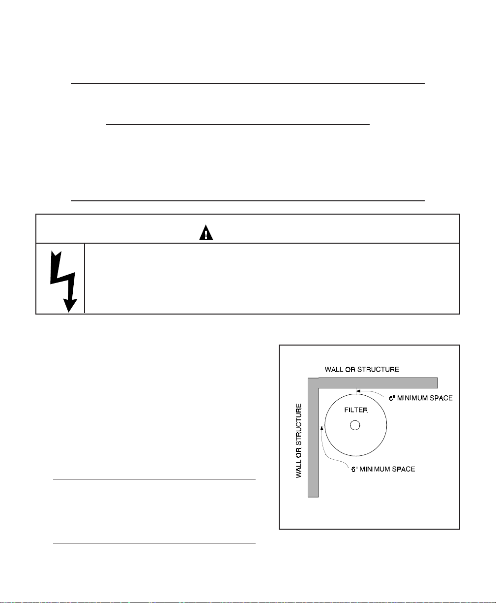
1. The filter should be mounted on a level concrete slab. Position the filter so that the
instructions, warnings and pressure gauge are visible to the operator. Also, position the filter
so that the piping connections, control valve and drain port are convenient and accessible for
servicing and winterizing.
2. Install electrical controls (e.g., on/off switches, timers control systems, etc.) at least five (5)
feet from the filter. This will allow you enough room to stand clear of the filter during system
start up, see Figure 1.
Pentair Pool Products
1620 Hawkins Ave., Sanford, NC 27330 • (919)774-4151
10951 West Los Angeles Ave., Moorpark, CA 93021 • (805) 523-2400
REV D. 5-1-01 P/N 99750000P/N 99750000 REV D. 5-1-01
1
Page 2
3 . Provide sufficient space above the filter to remove the filter lid and cartridge for cleaning and
servicing. This distance will vary with the model of filter you are using. See Table 1 for the
required vertical clearance above the filter.
TABLE 1
Model Size Vertical Clearance Req.
56109000 25 sq. ft. 24 in.
56159000 35 sq. ft. 2 4 in.
56209000 50 sq. ft. 4 4 in.
56359000 75 sq. ft. 4 4 in.
56759000 100 sq. ft. 6 4 in.
56760000 150 sq. ft. 7 4 in.
W ARNING
Risk of electrical shock or electrocution. Position the filter and High Flow Air Relief
Valve to safely direct water drainage and purged air or water. Water discharged from
an improperly positioned filter or valve can create an electrical hazard that can cause
severe personal injury as well as damage property.
4 . When installing the High Flow Manual Air Relief
Valve position the filter to safely direct water
drainage. Rotate the High Flow Manual Air Relief
Valve to safely direct purged air or water. Water
discharged from an improperly positioned filter or
valve can create an electrical hazard as well as
damage property.
5. Always follow procedures published by solvent
cement manufacturers for preparation and gluing of
pipe to the filter.
NOTE
On threaded valve connections use only Teflon tape,
100% Teflon tape, 100% Teflon paste, or Permatex #2
to seal the threads.
2
Figure 1.
Page 3

6. THE FILTER BASE IS ABS MATERIAL. WHEN PVC PIPE IS BEING USED THE CORRECT ABS
TO PVC SOLVENT PIPE CEMENT MUST BE USED. WE RECOMMEND WELD-ON #793 OR
EQUIVALENT.
7 . An additional inlet port is provided in the base for easier installation. Select the desired inlet port
and plug the other inlet port with 1½ in. plug provided, (item #13).
a. If your filter has slip ports use item 13, 1½ in. ABS slip plug. Use ABS to ABS solvent, we
recommend WELD-ON #771 or equivalent. A ½ in. plug (item #14) is also provided for use as
a drain plug.
b. If your filter has threaded ports use item 13, 1½ in. threaded plug. Use only teflon tape, 100%
teflon paste, or Permatex #2 to seal the threads. Use of other materials could damage the
equipment.
8 . The 25, and 50 sq. ft. models are equipped with Turbo-Flo by-pass valve. If by-pass is not desired,
plug off with item #16 using WELD-ON #771 or equivalent.
9 . The maximum working pressure of this filter is 50 p.s.i. Never subject this filter to pressure in
excess of this amount, even when conducting hydrostatic pressure tests. Pressures above 50 p.s.i.
can cause the lid to be blown off, which can result in severe injury, death or property damage.
When performing hydrostatic pressure tests or when testing for external leaks of the completed filtration and plumbing system, insure that the Maximum Pressure that the filtration
system will be subjected to DOES NOT EXCEED THE MAXIMUM WORKING PRESSURE OF
ANY OF THE COMPONENTS CONTAINED WITHIN THE SYSTEM. In most cases, the
maximum pressure will be stated on each component of the system.
If doubt exists as to the pressure to which the system will be subjected, install an ASME
approved automatic Pressure Relief or Pressure Regulator in the circulation system for the
lowest working pressure of any of the components in the system.
REV D. 5-1-01 P/N 99750000P/N 99750000 REV D. 5-1-01
3
Page 4
SECTION II. FILTER OPERATION
WARNING
THIS FILTER OPERATES UNDER HIGH PRESSURE. WHEN ANY PART OF THE
CIRCULATING SYSTEM (e.g., FILTER LID, PUMP, FILTER, VALVES, ETC.) IS
SERVICED, AIR CAN ENTER THE SYSTEM AND BECOME PRESSURIZED.
PRESSURIZED AIR CAN CAUSE THE LID TO BLOW OFF WHICH CAN RESULT IN
SEVERE INJURY, DEATH, OR PROPERTY DAMAGE. TO AVOID THIS POTENTIAL
HAZARD, FOLLOW THESE INSTRUCTIONS.
1. BEFORE REPOSITIONING VALVES AND BEFORE BEGINNING THE ASSEMBLY,
DISASSEMBLY, OR ADJUSTMENT OF THE LID OR ANY OTHER SERVICE OF
THE CIRCULATING SYSTEM: (A) TURN THE PUMP OFF AND SHUT OFF ANY
AUTOMATIC CONTROLS TO ASSURE THE SYSTEM IS NOT INADVERTENTLY
STARTED DURING THE SERVICING. (B) OPEN HIGH FLOW MANUAL AIR
RELIEF VALVE, AND (C) WAIT UNTIL ALL PRESSURE IS RELIEVED -PRESSURE
GAUGE MUST READ ZERO (0).
2. WHENEVER INSTALLING THE FILTER LID, FOLLOW THE FILTER LID
INSTALLATION INSTRUCTIONS EXACTLY.
3. ONCE SERVICE ON THE CIRCULATING SYSTEM IS COMPLETE, FOLLOW
SYSTEM RESTART INSTRUCTIONS EXACTLY.
4. MAINTAIN CIRCULATION SYSTEM PROPERLY. REPLACE WORN OR
DAMAGED PARTS IMMEDIATELY (e.g., lid, knob, pressure gauge, relief valve,
O-rings, etc.)
5. BE SURE THAT THE FILTER IS PROPERLY MOUNTED AND POSITIONED
ACCORDING TO INSTRUCTIONS PROVIDED.
4
Page 5

A. GENERAL INFORMATION
1. This filter operates under pressure. When assembled properly and operated without air in the
water system, this filter will operate in a safe manner.
2 . The maximum working pressure of this filter is 50 p.s.i. Never subject this filter to pressure in
excess of this amount - even when conducting hydrostatic pressure tests. Pressures above 50
p.s.i. can cause the lid to be blown off, which can result in severe injury, death or property damage.
When performing hydrostatic pressure tests or when testing for external leaks of the
completed filtration and plumbing system, insure that the Maximum Pressure that the filtration
system will be subjected to DOES NOT EXCEED THE MAXIMUM WORKING PRESSURE OF
ANY OF THE COMPONENTS CONTAINED WITHIN THE SYSTEM. In most cases, the
maximum pressure will be stated on each component of the system.
If doubt exists as to the pressure to which the system will be subjected, install an ASME
approved automatic Pressure Relief or Pressure Regulator in the circulation system for the
lowest working pressure of any of the components in the system.
3 . The pressure gauge is the primary indicator of how the filter is operating. Maintain your pressure
gauge in good working order.
WARNING
Your filter is a piece of machinery, do not tamper with it, attempt to disassemble it or
otherwise adjust it unless you fully understand it's operation. Serious injury or death
can occur if the equipment is improperly handled. Consult a pool service professional
for maintenance and service assistance.
4 . Clean your filter when pressure reads between 8-10 p.s.i. higher than the original starting pressure.
Your filter pressure reading will increase as it removes dirt from your pool. However, this buildup
of pressure will vary due to different bathing loads, temperature, weather conditions, etc.
a. MY ORIGINAL STARTING PRESSURE IS ___________ p.s.i. (pounds per square inch). I
SHOULD CLEAN THE FILTER CARTRIDGES AT __________ p.s.i.
NOTE
Whenever the cartridge filter is being used for the first time on a new swimming pool, or when
extra water clarity is desired, introduce into the system a one (1) pound coffee can (½ pound of
diatomaceous earth) for every 100 square feet of filter area. Mix the diatomite with water and
pour it into the skimmer after the pump is primed and the system is operating.
REV D. 5-1-01 P/N 99750000P/N 99750000 REV D. 5-1-01
5
Page 6

B. FILTER LID INSTALLATION INSTRUCTIONS.
1 . Ensure that the O-ring is in position in the lid then locate lid on rod, centering lid in cartridge
opening.
2 . Secure the entire assembly by using the top knob to firmly seal the lid against the O-ring and the
body.
3 . Before starting pump open the High Flow Manual Air Relief Valve on the filter lid.
4 . Stand clear of the filter tank, then start the pump.
5 . Close the High Flow Manual Air Relief Valve when a steady stream of water is flowing. This
indicates that all air is bled from tank.
C. SYSTEM RESTART INSTRUCTIONS
WARNING
THIS FILTER OPERATES UNDER HIGH PRESSURE. WHEN ANY PART OF THE
CIRCULATING SYSTEM (e.g., FILTER LID, PUMP, FILTER, VALVES, ETC.) IS
SERVICED, AIR CAN ENTER THE SYSTEM AND BECOME PRESSURIZED.
PRESSURIZED AIR CAN CAUSE THE LID TO BE BLOWN OFF WHICH CAN RESULT
IN SEVERE INJURY, DEATH, OR PROPERTY DAMAGE. TO AVOID THIS
POTENTIAL HAZARD, FOLLOW THESE INSTRUCTIONS.
1. Open the High Flow Air Relief Valve until it snaps into the full open position (this only requires a
quarter turn counterclockwise). Opening this valve rapidly releases air trapped in the filter.
2 . Stand clear of the filter tank, then start the pump.
3 . Close the High Flow Air Relief Valve after a steady stream of water appears.
4 . The system is not working properly if either of the following conditions occur.
a. A solid stream of water does not appear within 30 seconds, after the pump's inlet basket fills
with water.
b. The pressure gauge indicates pressure before water outflow appears.
If either condition exists, shut off the pump immediately, open valves in the water return line to
relieve pressure, and clean the High Flow Manual Air Relief Valve, see Section F, Cleaning the
High Flow Air Relief Valve. If the problem persists, call 1-800-831-7133 for assistance.
6
Page 7

D. CLEANING FILTER MANUALLY
CAUTION
The following information should be read carefully since it outlines the proper manner of care and
operation for your filter system. As a result of following these instructions and taking the necessary
preventative care, you can expect maximum efficiency and life from your filtration system.
1. Turn the pump off, shut off any automatic controls to ensure that the system is not inadvertently
started during servicing.
2 . Open the filter High Flow Air Relief Valve (and, the waste drain valve, or plug, if your system has
one).
3 . Remove hair and lint strainer pot lid and clean basket. Replace basket and secure lid.
4 . Unscrew large center knob (item 1) and remove top lid assembly (item 4).
5 . Remove drain plug in base of the filter (item 11) to allow excess water and residue to drain from the
tank.
6. Remove cartridge or cartridges.
7. Using a garden hose without a nozzle, direct water spray at cartridges to dislodge and wash away
accumulated foreign matter. Flush each cartridge inside-out.
CAUTION
Please heed all manufacturers' posted instructions, warnings and cautions when
using Baquacil® or Baqua Clean®.
REV D. 5-1-01 P/N 99750000P/N 99750000 REV D. 5-1-01
7
Page 8

NOTE
Special care must be taken when cleaning filter cartridges used in a swimming pool or spa using
Baquacil as a sanitizer. Because of the way Baquacil works, the filter element must be cleaned
more thoroughly and more frequently than in a chlorine system, If extreme care is not taken to
completely remove all residue from the filter media a buildup will occur. This buildup will significantly shorten the life of the filter element.
Baquacil is a mild coagulant which combines bacterial cells as well as other small particles
contributed by the environment, bathers, etc. into particles large enough to be trapped by the
filter. In comparison with all other trapped contaminants in a typical pool or spa the amount of
bacterial cells that are deposited on the filter is minimal. The resulting deposit is a gray sticky film
which can only be removed with Baqua Clean. If TSP or any TSP type cleaner is used prior to
stripping the film, the cleaner and the fray film will combine to form a gum-like substance. Once
this occurs, the substance cannot be removed from the media and the filter cartridge must be
replaced.
8. Direct water spray to wash out the inside of the tank body. Water and debris will drain out through
the open drain port.
9. Place cartridge or cartridges into the tank and press firmly into filter base. Ensure that the internal
air bleed assembly is in place and not damaged.
10 . Replace tank drain plug (item 11) in base of filter. Put filter lid (item 3) in place so that center rod
protrudes.
11. Secure the entire assembly by using the top knob (item 1) to firmly seal the lid against the O-ring
and the body.
E. REPLACING FILTER CARTRIDGES
Filter Cartridge life will vary with pool conditions such as
bather load, wind, dust, etc. You can expect an average
cartridge life of 3 years under normal conditions.
1 . To replace cartridges follow steps in section D, Cleaning
Filter, eliminating step D.7
NOTE
Anytime the filter tank is opened and/or element assembly is
removed, be sure to generously coat the filter O-ring with
silicone lubricant before reassembling the unit. Do not use
petroleum base lubricants because they have a deteriorating
effect on rubber.
8
Figure 2.
Page 9

F. CLEANING THE HIGH FLOW MANUAL AIR RELIEF VALVE
1. Turn the pump off and shut off any automatic controls to ensure that the system is not
inadvertently started during servicing.
2. OPEN THE HIGH FLOW MANUAL AIR RELIEF VALVE UNTIL IT SNAPS INTO THE FULL
OPEN POSITION, THEN WAIT UNTIL ALL PRESSURE IS RELIEVED.
3 . With the relief valve attached to the filter tank, pull out the locking tabs and remove the valve stem
and cover assembly with a counterclockwise and lifting motion, see Figure 2.
4 . Clean debris from the valve stem and body. Verify that the filter tank's air passage is open by
inserting a 5/16" drill bit through the valve body. Verify that the O-rings are in good condition,
properly positioned, and lubricated with a silicone base lubricant.
5. Reinstall the valve stem and cover assembly with a downward and clockwise motion until it snaps
into position.
SECTION III. TROUBLE SHOOTING
A. Air entering your filter is dangerous and can cause the lid to blow off. Correct any conditions in your
filtration system that allow air to enter the system.
1 . Some common ways to identify air entering the system:
a. Low water level in pool or spa - skimmer is starving for water with pump running. Add water
to pool or spa.
b. Air bubbles or low water level in pump hair and lint pot are caused by; low water level,
clogged skimmer basket, split suction cleaner hose, leak in pump hair and lint pot lid, or leak in
pump suction line.
c. Air bubbles coming out of water return lines into pool or spa with pump running, see items 1.a
and 1.b of this section.
d. Air is discharged from the High Flow Manual Air Relief Valve on top of the filter when the
valve is opened with the pump running, see items 1.a and 1.b of this section, above.
e. Before you assemble the lid, ensure that the internal air bleed assembly is in place and not
clogged or damaged.
B . Until the water initially put into the pool has been completely filtered, short filter cycles in between
cleanings are normal. In most cases pool owners are dismayed by the undesirable color and appearance of
water in a newly filled pool. Plaster dust can be responsible for short filter cycles, requiring frequent
cleaning.
REV D. 5-1-01 P/N 99750000P/N 99750000 REV D. 5-1-01
9
Page 10

C. If pressure drops on gauge, check skimmer basket and pump basket first for debris. If the baskets are
clean, shut off power to pump and turn off any automatic controls. Then turn motor shaft with your
fingers. If it turns freely then the pump must be disassembled and the impeller checked to see if it is
clogged. If it is not frozen or clogged then there is an obstruction in the line between the pool and the
pump.
D . The pressure gauge is an important part of the filter system. It is your primary indicator of how the
system is operating. Maintain your pressure gauge in good working order. Check the operation of
your pressure gauge in the following manner:
1. The pressure gauge should go to zero (0) when the system is turned off and pressure is relieved.
2. The pressure gauge should indicate pressure when the system is operating.
3. The pressure gauge should be readable and not damaged in any way.
4 . Replace the pressure gauge if it is not meeting the requirements of items D.1 through D.2 of this
section, above.
10
Page 11

SECTION IV. REPLACEMENT PARTS.
Item Part Description
No. No.
1 570069 Knob, plastic cartridge filter top
2 530032 Gauge, Pressure
3 570059 Top ABS
4 570057 Element 25 sq. ft. Filter
4 570142 Element 35 sq. ft. Filter
4 570143 Element 75 sq. ft. Filter
4 570144 Element 100 sq. ft. Filter
4 570058 Element 50 sq. ft. Filter
5 570079 Assy, Bottom 25 & 35 sq. ft.
5 570080 Assy, Bottom 50 & 75 sq. ft.
5 570081 Assy, Bottom 100 sq. ft.
5 570085 Assy, Bottom 150 sq. ft.
6 570067 O-ring
7 570061 Rod, s/s THD, 25 & 35 sq. ft.
7 570062 Rod, s/s THD, 50 & 75 sq. ft.
7 570077 Rod, s/s THD, 100 sq. ft.
7 570086 Rod, THD 150 sq. ft.
8 982098 Air relief manual valve assy.
9 570073 O-ring
10 570083 Adapter ABS, 150 sq. ft. filter
11 570071 Plug, Drain
12 570065 O-ring
13 570129 Reducer plug 1½ in. SLP ½ in.
13 570130 Reducer plug 1½ in. THD ½ in.
14 793012 Plug ½ in.
15 550271 Air bleed assy., 25-35 sq. ft.
15 550272 Air bleed assy., 50-75 sq. ft.
15 550273 Air bleed assy., 100 sq. ft.
15 550274 Air bleed assy., 150 sq. ft.
16 570106 Plug
REV D. 5-1-01 P/N 99750000P/N 99750000 REV D. 5-1-01
11
Page 12

SAVE THESE INSTRUCTIONS
Pentair Pool Products
1620 Hawkins Ave., Sanford NC 27330 • (919)774-4151
10951 West Los Angeles Ave., Moorpark, CA 93021 • (805) 523-2400
12
 Loading...