

Page 1
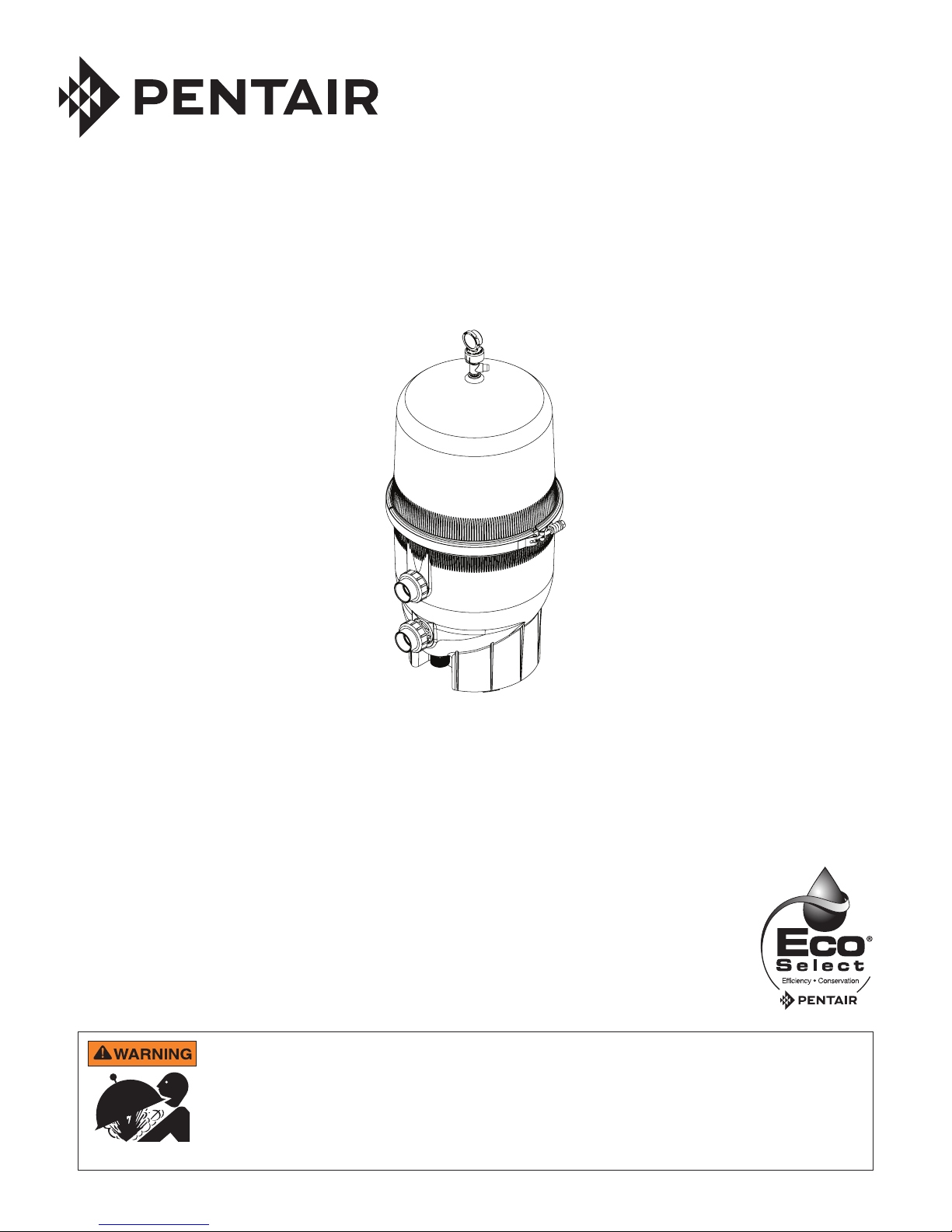
CLEAN AND CLEAR® PLUS
CARTRIDGE FILTER
IMPORTANT SAFETY INSTRUCTIONS
READ AND FOLLOW ALL INSTRUCTIONS
SAVE THESE INSTRUCTIONS
Pressurized air can cause the lid to separate from the tank with great force. To reduce the
risk of severe injury or death, relieve pressure by opening air relief valve before opening
filter. Before starting the pump after servicing, ensure that clamp band is correctly fastened.
See Important Warnings and Safety Instructions (page iii) and follow all instructions exactly;
including the Opening the Filter (page 4), Installing the Filter Lid and Clamp Ring (page 5), and
Start-Up Instructions (page 6).
INSTALLATION AND
USER’S GUIDE
Page 2

i
CUSTOMER SERVICE / TECHNICAL SUPPORT
If you have questions about ordering Pentair Aquatic Systems replacement parts, and pool products, please contact:
Customer Service and Technical Support, USA
(8 A.M. to 4:30 P.M. — Eastern/Pacific Times)
Phone: (800) 831-7133
Fax: (800) 284-4151
Web site
Visit www.pentairpool.com or www.staritepool.com for
information about Pentair products.
TABLE OF CONTENTS
For Your Safety .....................................................
Customer Service / Technical Support ..............
Important Warnings and Safety Instructions ....
General Information ............................................
Filter Overview
General Operation Information
Pressure Tests
Installation ............................................................
Filter Location
Filter Plumbing
Installing the Manual Air Relief Valve
Opening, Closing and Start-Up ..........................
Opening the Filter
Installing the Filter Lid and Clamp Ring
Start-Up Instructions
i
ii
iii
1
1
1
1
2
2
2
3
4
4
5
6
Sanford, North Carolina (8 A.M. to 4:30 P.M. ET)
Phone: (919) 566-8000
Fax: (919) 566-8920
Moorpark, California (8 A.M. to 4:30 P.M. PT)
Phone: (805) 553-5000 (Ext. 5591)
Fax: (805) 553-5515
Maintenance .........................................................
Maintaining the Pressure Gauge
Cleaning the Manual Air Relief Valve
When to Clean Your Filter
Cleaning the Filter Cartridges
Acid Soaking the Filter Cartridges
Replacing Filter Cartridges
Troubleshooting ..................................................
Technical Data .....................................................
Flow Rates
Dimensional Drawings
Replacement Parts ..............................................
Illustrated Parts View
Parts List
On-Product Safety Labels
7
7
7
8
8
9
10
11
12
12
12
13
13
14
15
P/N 178558 Rev. P 7/6/17
CLEAN AND CLEAR® PLUS Cartridge Filter Installation and User’s Guide
Page 3
IMPORTANT WARNINGS AND SAFETY INSTRUCTIONS
IMPORTANT NOTICE:
This guide provides installation and operation instructions for the Clean and Clear® Plus Cartridge Filter. Consult Pentair
Water Pool and Spa, Inc. with any questions regarding this equipment.
Attention Installer: This guide contains important information about the installation, operation and safe usage of this product. This
information should be given to the owner and/or operator of this equipment after installation.
Attention User: This manual contains important information that will help you in operating and maintaining this filter. Please retain it
for future reference.
This is the safety alert symbol. When you see this symbol on your system or in this manual, look for one of the
following signal words and be alert to the potential for personal injury.
Warns about hazards that can cause death, serious personal injury, or major property damage if ignored.
Warns about hazards that may cause death, serious personal injury, or major property damage if ignored.
Warns about hazards that may or can cause minor personal injury or property damage
if ignored.
NOTE Indicates special instructions not related to hazards.
Carefully read and follow all safety instructions in this manual and on equipment. Keep safety labels in good condition; replace if missing
or damaged.
ii
Consumer Information and Safety
This filter is designed and manufactured to provide many years of safe and reliable service when installed, operated and maintained
according to the information in this manual and the installation codes referred to in later sections. Throughout the manual, safety warnings
and cautions are identified by the “ “ symbol. Be sure to read and comply with all of the warnings and cautions.
Before installing this product, read and follow all warning notices and instructions which are included. Failure to
follow safety warnings and instructions can result in severe injury, death, or property damage. Call (800) 831-7133
for additional free copies of these instructions or replacement safety labels.
Do not operate the filter until you have read and understand clearly all the operating instructions
and warning messages for all equipment that is a part of the pool circulating system. The following instructions are
intended as a guide for initially operating the filter in a general pool installation. Failure to follow all operating instructions and warning
messages can result in property damage or severe personal injury or death.
Due to the potential risk that can be involved it is recommended that the pressure test be kept to the minimum time
required by the local code. Do not allow people to work around the system when the circulation system is under
pressure test. Post appropriate warning signs and establish a barrier around the pressurized equipment. If the
equipment is located in an equipment room, lock the door and post a warning sign.
Never attempt to adjust any closures or lids or attempt to remove or tighten bolts when the system is pressurized.
These actions can cause the filter to separate and could cause severe personal injury or death if they were to
strike a person.
This filter must be installed by a qualified pool serviceman in accordance with all applicable local codes and
ordinances. Improper installation could result in death or serious injury to pool users, installers, or others and may
also cause damage to property.
Always disconnect power to the pool circulating system at the circuit breaker before servicing the filter. Ensure that
the disconnected circuit is locked out or properly tagged so that it cannot be switched on while you are working on
the filter. Failure to do so could result in serious injury or death to serviceman, pool users or others due to electric
shock.
DO NOT permit children to use this product.
CLEAN AND CLEAR® PLUS Cartridge Filter Installation and User’s Guide
Page 4
iii
IMPORTANT WARNINGS AND SAFETY INSTRUCTIONS
THIS SYSTEM OPERATES UNDER HIGH PRESSURE
When any part of the circulating system, (e.g., closure, pump, filter, valve(s), etc.), is serviced, air can enter the
system and become pressurized. Pressurized air can cause the top closure to separate which can result in severe
injury, death, or property damage. To avoid this potential hazard, follow these instructions:
1. Let air and pressure out of system before and after servicing.
a. Shut off pump and RELIEVE PRESSURE by opening the manual air/pressure relief valve before
servicing, including before tightening the clamp bolt. Follow the Opening the Filter instructions
exactly (page 4).
b. Follow Start-Up Instructions exactly after completing service (page 6). The air/pressure relief valve
must remain open until water comes out, allowing all air out of the system.
2. Install lid and clamp ring properly.
a. Follow the Installing the Filter Lid and Clamp Ring instructions exactly (page 5). The nut must be
tightened until the spring is compressed when clamp is installed. Tap the clamp with a rubber
mallet or similar tool after clamp installation to ensure proper seating.
3. Maintain circulation system properly to help prevent air entering the system.
a. Replace worn or damaged parts immediately, (e.g., closure, pressure gauge, valve(s), O-rings,
etc.).
b. Maintain proper water level in the pool or spa.
4. Verify that the return line to the pool is unobstructed. Ensure return valves are open and any winterizing
plugs are removed.
AVOID DAMAGING SYSTEM
Never Exceed Maximum Pressure of Components. The maximum working pressure of this filter is 50 psi. Never
subject this filter to higher pressure, even when conducting hydrostatic pressure tests. Pressures above 50 psi can damage your filter.
Be sure the maximum pressure of the filter system does not exceed the maximum pressure of any components within the system
(typically stated on each component), including during hydrostatic or external leak tests. Exceeding the maximum pressure of a
component can result in that component failing. If you do not know the pool or spa system operating pressure, install an ASME
approved automatic Pressure Relief or Pressure Regulator in the circulation system set to the lowest working pressure of any of the
components in the system.
Certain codes may require pressure testing the system. Performing pressure tests increases the risk of
component failure. Due to the potential risk that can be involved, keep the pressure test to the minimum time
required by the local code and take precautions. If pressure testing is necessary, follow these precautions:
1. Keep people away.
a. Do not allow people to work around the system when the circulation system is under pressure test.
Post appropriate warning signs and establish a barrier around the pressurized equipment. If the
equipment is located in an equipment room, lock the door and post a warning sign.
2. Never exceed maximum operating pressure.
a. When performing hydrostatic pressure tests or when testing for external leaks of the completed filtration
and plumbing system, ensure that the Maximum Pressure that the filtration system will be subjected
to does not exceed the maximum working pressure of any of the components contained within the
system.
CLEAN AND CLEAR® PLUS Cartridge Filter Installation and User’s Guide
Page 5
1
GENERAL INFORMATION
THIS SYSTEM OPERATES UNDER HIGH PRESSURE.
When any part of the circulating system (e.g., Lock Ring, Pump, Filter, Valves, etc.) is serviced, air can enter the system and become
pressurized. Pressurized air can cause the lid to separate which can result in serious injury, death, or property damage. To avoid this
potential hazard, follow the instructions below.
Filter Overview
• Large filter area designed for increased debris capacity
• NSF Listed
• High Flow™ Manual Air Relief Valve provided
• 1.5" x 2" Bulkhead Unions allows for easy piping
installation
General Operation Information
Read and follow all instructions and warnings before installing
or servicing your filter. Proper installation and operation can
prevent unnecessary repairs and maintenance.
Your filter is a piece of machinery, do not tamper
with it, attempt to disassemble it or otherwise adjust
it unless you fully understand it's operation. Serious
injury or death can occur if the equipment is improperly
handled. Consult a pool service professional for
maintenance and service assistance.
1. The Clean and Clear® Plus Cartridge Filter operates
under pressure and operates in a safe manner if clamped
properly and without air in the circulating system.
2. The maximum working pressure of this filter is 50 psi.
Never subject this filter to pressure in excess of this
amount, even when conducting hydrostatic pressure
tests.
3. Be sure the maximum pressure of the filter system does
not exceed the maximum pressure of any components
within the system during hydrostatic or external leak
tests. Consult the maximum pressure stated on each
component of the system.
4. The pressure gauge is the primary indicator of how the
filter is operating. Maintain your pressure gauge in good
working order.
5. Clean your filter when pressure reads between 8-10
psi higher than the “Original Starting Pressure”, or
when significant reduction in flow is noticed. The
pressure reading increases as it filters dirt from your
pool. This build up of pressure will vary due to different
bathing loads, temperature, environmental conditions,
etc.
Note: When using a variable speed pump the “Original
Starting Pressure” will be dependent on the pump speed
(RPM) when recording the original operating pressure.
Record the “Original Pump RPM” in Table 1.
Pressure Tests
When performing hydrostatic pressure tests or when
testing for external leaks of the completed filtration and
plumbing system, ensure that the Maximum Pressure
that the filtration system will be subjected to DOES NOT
EXCEED THE MAXIMUM WORKING PRESSURE OF ANY OF
THE COMPONENTS CONTAINED WITHIN THE SYSTEM. In
most cases, the maximum pressure will be stated on
each component of the system.
If you do not know the pool or spa system operating
pressure, install an ASME approved automatic
Pressure Relief or Pressure Regulator in the
circulation system set to the lowest working pressure
of any of the components in the system.
Table 1
ORIGINAL STARTING PRESSURE IS: ________ psi.
(pounds per square inch)
SERVICE THE MEDIA AT: __________ psi.
ORIGINAL PUMP RPM: __________ rpm.
(for Variable Speed Pumps Only)
CLEAN AND CLEAR® PLUS Cartridge Filter Installation and User’s Guide
Page 6
2
INSTALLATION
This filter must be installed by a qualified pool technician in accordance with all applicable local codes and
ordinances. Improper installation could result in death or serious injury to pool users, installers, servicers, or others
and may also cause damage to property.
For Installation of Electrical Controls at Equipment Pad (ON/OFF Switches, Timers, Control Systems and
Automation) Install all electrical controls at the equipment pad, such as ON/OFF switches, timers, control systems,
etc. to allow the operation (startup, shutdown or servicing) of any pump or filter so the user does not place any
portion of his/her body over or near the pump strainer lid, filter lid or valve closures. This installation should allow
the user enough space to stand clear of the filter and pump strainer lid during system startup, shutdown or servicing
of the system filter.
Filter Location
1. The Clean and Clear® Plus Cartridge Filter should be mounted on a
level concrete slab. Position the filter so that instructions, warnings
and the pressure gauge are visible to the operator and readable. It
also should be positioned so that the piping connections, control valve
and waste drain plug are convenient and accessible for servicing and
winterizing.
2. Be certain to install electrical controls (e.g., on/off switches, timers,
control systems, etc.) so that the user is allowed enough space to stand
clear of the filter and pump during startup, shutdown or servicing.
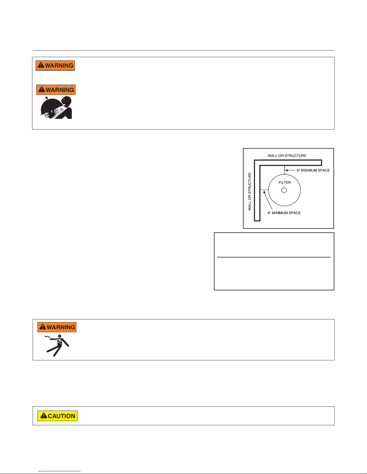
3. Allow sufficient clearance around the filter to permit visual verification
that the clamp is properly installed around the tank flanges,
see Figure 1.
Note: See page 5, Installing the Filter Lid and Clamp Ring.
4. Allow sufficient space above the filter to remove the filter lid for
cleaning and servicing. This distance will vary with the model
of filter you are using. See Table 2 for the required vertical
clearance.
5. Position the filter to safely direct water drainage away from
electrical equipment or anything that might be damaged.
6. Position the High Flow™ Manual Air Relief Valve to safely direct purged air or water (See page 3, Installing
the Manual Air Relief Valve).
Model No. Size Vert. Clearance Req.
(From Ground Level)
CCP240 240 sq. ft. 56in.
CCP320 320 sq. ft. 62in.
CCP420 420 sq. ft. 68in.
CCP520 520 sq. ft. 74in.
Table 2
Figure 1
RISK OF ELECTRICAL SHOCK OR ELECTROCUTION. Water discharged from an improperly positioned filter or
valve can create an electrical hazard that can cause severe personal injury as well as damage property.
Filter Plumbing
Make all plumbing connections in accordance with local plumbing and building codes. Do not use pipe joint compound,
glue or solvent on the bulkhead connections. The provided filter plumbing connections include an O-ring seal.
Use PTFE or silicone based lubricants when lubricating the O-rings on the union and bulkhead couplings. Use of
petroleum based products will damage the equipment.
CLEAN AND CLEAR® PLUS Cartridge Filter Installation and User’s Guide
Page 7

3
Installing the Manual Air Relief Valve
Figure 2
The High Flow manual air relief valve and pressure gauge are
included with this filter to help ensure safe operation of the
equipment. Always maintain these components in good working condition.
1. Remove the High Flow™ Manual Air Relief Valve and the
pressure gauge from the accessories package included with your
Clean and Clear® Plus Cartridge Filter.
2. Thread the manual air relief valve into the threaded hole at the top
of the filter tank.
Note: Hand tighten only! Over tightening the valve can cause
damage to the tank or valve connection threads.
3. Verify that the valve is positioned to safely direct purged air or
water away from electrical equipment or anything that might be
damaged.
RISK OF ELECTRICAL SHOCK OR ELECTROCUTION. Water discharged from an improperly positioned
filter or valve can create an electrical hazard that can cause severe personal injury as well as damage
property.
4. Remove the plug from the top of the manual air relief valve with a 9/16" wrench.
5. Wrap the pressure gauge connection threads with thread seal tape (two full wraps of tape will be enough).
6. Thread the pressure gauge into the top of the manual air relief valve. Hand tighten only!
7. Follow Start-up Instructions exactly (page 6).
FILTER
TANK
PRESSURE
GAUGE
VALVE
PLUG
CLEAN AND CLEAR® PLUS Cartridge Filter Installation and User’s Guide
Page 8

4
OPENING, CLOSING, AND START-UP
The following information should be read carefully since it outlines the proper manner of care and operation for your filter
system. As a result of following these instructions and taking the necessary preventative care, you can expect maximum
efficiency and life from your filtration system.
Opening the Filter
Follow these instructions exactly to prevent the lid from separating during system start-up, operation or servicing.
This filter operates under high pressure. Air can also enter the system and become pressurized.
If there is air in the system, there will be positive pressure that could cause the lid to separate from the filter when you
release the clamp or during system start-up or operation (see Important Warnings and Safety Instructions, page ii-iii).
If there is no air in the system, there may be negative pressure, which would make the system hard to open.
Follow these instructions exactly - opening the relief valve equalizes the pressure and releases any trapped air within
the system, making it safe and easy to open.
RECOMMENDED EQUIPMENT:
• Ratchet Wrench
• 7/8" Socket
• Socket Extender (if needed)
PROCEDURE:
Clamp Ring
1. Shut off pump and relieve pressure.
a. Turn the pump OFF, shut OFF any automatic
controls (e.g., timers), and disconnect power to
ensure that the system is not inadvertently started
during maintenance.
b. Open the High Flow™ Manual Air Relief Valve by
turning the valve cover assembly counter-clockwise
until it snaps into the full open position.
Clamp Ring,
Closed Position
c. Stand clear of the filter and wait until all pressure is
relieved. Pressure gauge must read zero (0 psi).
2. Open the waste drain plug on the bottom of the Clean
and Clear® Plus Cartridge Filter. Allow all water to drain
from the bottom of the filter tank.
3. Loosen the clamp's barrel nut with a 7/8" wrench,
allowing the spring coils to decompress. See Figure 4.
Remove the barrel nut, spring and two washers from the
Clamp Ring,
Open Position
T-bolt and place them in a safe place where they will not
be lost.
4. Once the spring has fully decompressed the clamp
assembly will rest in the open position. Carefully lift the
filter lid straight up from the lower body of the filter. If
the lid is tightly sealed to the filter body you may have to
gently push the filter lid from side to side in order to separate the lid from the bottom tank manifold.
Figure 3
Sm. Washer
Lrg. Washer
Barrel
Nut
Spring
T-Bolt
Loosen with
7/8" Wrench
Figure 4
DO NOT use the relief valve as a handle or lever since this may damage the valve.
5. Place the tank lid in a safe place where it will not be damaged while performing any maintenance.
NOTE: Attempt to minimize the amount of debris that comes in contact with the tank O-ring while it is exposed. This
will help prolong the life of the O-ring.
CLEAN AND CLEAR® PLUS Cartridge Filter Installation and User’s Guide
Page 9

Installing the Filter Lid and Clamp Ring
Follow these instructions exactly to prevent the lid from separating from the filter during system start-up
or operation. (See Important Warnings and Safety Instructions, page ii-iii).
RECOMMENDED EQUIPMENT:
• Ratchet Wrench
• 7/8" Socket
• Socket Extender (if needed)
• Rubber Mallet
PROCEDURE:
1. Be sure the O-ring is clean and in position in the
lower tank half. Press the Clean and Clear® Plus
Cartridge Filter lid onto the lower half so the O-ring
fits in between the tank halves.
2. Hold the ends of the clamp ring apart and place over
both upper and lower tank flanges. Bring the ends of
the filter clamp together.
3. Insert the T-bolt through the other side of the clamp
and hold together.
4. Place the small washer onto the T-bolt.
5. Place the spring, large washer and barrel nut onto
the T -bolt and tighten the nut by hand. Be sure the
clamp ring fits easily on the tank flanges.
6. After tightening by hand:
a. Use a 7/8 in. wrench (ratchet wrench
recommended) to tighten further.
b. Tap around the outside of the clamp ring
with a rubber mallet (or similar tool) multiple
times around the entire clamp to fit the clamp
properly.
c. Continue to tighten until the spring coils touch.
d. Tap around the entire clamp again and verify
the spring coils remain touching. If not, continue
to tighten the nut.
Note: The clamp is installed correctly only when the
spring coils remain touching after tapping the clamp
(See Figure 5).
7. Close the waste drain plug at the bottom of the filter.
8. Follow Start-Up Instructions exactly (see page 6).
Clamp Ring,
Open Position
Clamp Ring,
Closed Position
Spring Coils
Touching
Hand Tighten
onto T-Bolt
Tighten with
7/8" wrench
Figure 5
Note: Check the spring coils at least once a
month to ensure proper tension. If spring coils
do not touch then shut off pump and relieve
pressure and tighten the nut and tap filter clamp
until the coils touch.
5
DO NOT tighten the nut or attempt to adjust the clamp ring or lid while the system is turned on or under
pressure. This could cause the lid to separate from the filter
CLEAN AND CLEAR® PLUS Cartridge Filter Installation and User’s Guide
Page 10

6
Start-Up Instructions
Follow these instructions exactly to prevent the lid from separating from the filter during system start-up or
operation. (See Important Warnings and Safety Instructions, page ii-iii).
1. Be sure the spring on the clamp ring is fully compressed, with coils
touching.
2. Open the High Flow™ Manual Air Relief Valve by turning the valve cover
assembly a quarter turn counter-clockwise, until it snaps into the full open
position. See Figure 6.
3. Stand clear of the filter tank, then start the pump.
4. Watch for proper operation. The system is not working properly if:
a. The pressure gauge indicates pressure before water out-flow appears.
b. A solid stream of water does not appear within 30 seconds after the
pump's inlet basket fills with water.
c. Water leaks from where the two halves of the filter come together.
If any of these conditions exist, shut off the pump immediately. Open
the manual air relief valve to relieve pressure and clean the valve (see
Cleaning the Manual Air Relief Valve, page 7). If the problem persists,
call Pentair Technical Service at (800) 831-7133 for assistance.
5. After a steady stream of water appears, close the manual air relief valve
by turning the valve cover assembly a quarter turn clockwise.
6. The first time the system is started up, fill out Table 1 on page 1 and the
corresponding label on the equipment:
a. Record the "Original Starting Pressure"
b. Fill in the pressure at which to clean the filter (8-10 psi higher than
the "Original Starting Pressure").
c. If the system includes a variable speed pump, record "Original
Pump RPM".
Quarter turn counterclockwise to open
Closed Position
Open Position
Figure 6
CLEAN AND CLEAR® PLUS Cartridge Filter Installation and User’s Guide
Page 11

MAINTENANCE
Maintaining the Pressure Gauge
The pressure gauge is the primary indicator of how the system is operating, so correct functioning is critical.
Replace the pressure gauge (Pentair P/N 190058) if it does not meet the requirements below:
1. Pressure gauge should go to zero (0) when the system is turned off and pressure is relieved.
2. Pressure gauge should indicate pressure when the system is operating.
3. The pressure gauge should be readable and not damaged in anyway
Cleaning the Manual Air Relief Valve
RECOMMENDED EQUIPMENT:
• 5/16" Drill Bit (to check air passage)
• Silicone-based Lubricant (if needed)
PROCEDURE:
1. Shut off pump and relieve pressure.
a. Turn the pump OFF and shut OFF any automatic controls (e.g., timers)
and disconnect power to ensure that the system is not inadvertently
started during maintenance.
b. Open the manual air relief valve by turning the valve cover assembly a
quarter turn counter-clockwise until it snaps into the full open position.
c. Stand clear of the filter and wait until all pressure is relieved. Pressure
gauge must read zero (0 psi).
2. With the relief valve attached to the Clean and Clear® Plus Cartridge
Filter tank, pull out the locking tabs and unlock the valve stem and cover
assembly from the valve body with a counter-clockwise turn, see Figure 7.
3. Pull the valve stem and cover assembly straight up and away from the valve
body.
4. Clean and check the valve stem and body:
a. Clean off any debris.
b. Verify that the filter tank's air passage is open by inserting a 5/16"
drill bit through the valve body.
c. Verify that the valve stem O-rings are in good condition, properly positioned, and lubricated with a
silicone-base lubricant.
Figure 7
7
If needed, use only a PTFE or silicone-base lubricant on the O-rings. Use of petroleum based
products on O-rings will damage the equipment.
5. Reinstall the valve stem and cover assembly with a downward and clockwise motion until it snaps into
position.
CLEAN AND CLEAR® PLUS Cartridge Filter Installation and User’s Guide
Page 12

8
45°
When to Clean Your Filter
Proper operation can prevent avoidable repairs and maintenance.
Use the pressure gauge to determine when to clean your Clean and Clear® Plus Cartridge Filter for proper
operation. The pressure reading increases as dirt is filtered from your pool. This buildup of pressure will vary due to
different bathing loads, temperature, environmental conditions, etc.
Clean your filter when pressure reads between 8-10 psi higher than the “Original Starting Pressure” recorded in
Table 1 (page 1), or when significant reduction in flow is noticed.
Note: When using a variable speed pump the “Original Starting Pressure” will be dependent on the pump speed
(RPM) when recording the original operating pressure.
Cleaning the Filter Cartridges
1. Follow Opening the Filter (page 4) exactly.
2. Remove hair and lint strainer pot lid from the pump and clean
basket. Replace strainer basket and secure strainer pot lid.
3. Remove the compression spring and spring adapter by pulling
them straight up.
4. Separate the top manifold from the filter's cartridges and lay
the manifold to the side. See Figure 8.
5. Carefully remove each cartridge element separately.
6. Using a garden hose with a straight flow nozzle, wash down
the entire filter element. Wash from the top down, holding the
nozzle at a 45-degree angle to the cartridge (See Figure 9).
Pay special attention to the area between pleats.
7. For cartridges used in pools or spas where high levels of
perspiration, suntan lotions and other oils are present:
a. Soak the cartridge for at least one hour (overnight is most
effective) in one of the following:
• A commercial filter cleaner
Heed all manufacturers' instructions and warnings when using
polyhexamethylene biguanide sanitizers or other cartridge filter cleaner
solutions.
Figure 8
Compression Spring
and Spring Adapter
Top Manifold
• One cup trisodium phosphate (TSP) to five gallons of water
• One cup dishwasher detergent to five gallons of water
b. Rinse the cartridge to remove oils and cleaning solution.
Failure to remove all oils and cleaning solutions before acid soaking will result
in permanent restriction of water flow through the filter and will cause premature
cartridge failure.
8. Direct the water spray to wash out the inside of the tank body and bottom manifold.
Water and debris will drain out through the open drain plug.
9. Check gasket around outer lip of bottom plate. Gasket must be firmly and evenly set
around the entirety of the outer lip.
10. Place bottom manifold, four (4) cartridges and top manifold in place. Make sure the
spring and standpipe assembly are retained on the top manifold.
11. Be certain the O-ring is in position in the lower tank half and free of debris.
12. Follow Installing the Filter Lid and Clamp Ring exactly (page 5).
CLEAN AND CLEAR® PLUS Cartridge Filter Installation and User’s Guide
Figure 9
Page 13

Acid Soaking the Filter Cartridges
After an extended period of operation, it may be necessary to soak the cartridges in an acid solution. Acid soaking
will remove algae, calcium carbonate, iron and other mineral build-ups from the cartridges. If not removed, these
mineral deposits can lead to the restriction of water flow through the Clean and Clear® Plus Cartridge Filter and
can impede efficient operation of the equipment.
Muriatic acid is corrosive and can lead to inflammation or burns to body tissue.
ALWAYS wear rubber gloves, safety glasses and an N-95 dust mask when handling acid to prevent serious bodily
injury.
To prevent degradation of the acid by UV light, store muriatic acid in an opaque container and away from direct
sunlight.
RECOMMENDED EQUIPMENT:
• Large Plastic Container
• Garden Hose with a Straight Flow Nozzle
• Muriatic Acid (stored in opaque container)
• Rubber Gloves
• Safety Glasses
• N-95 Dust Mask
9
PROCEDURE:
1. Remove all oils and cleaning solutions from the cartridges.
Acid soaking without performing this step will result in permanent restriction of water flow through the filter and premature
cartridge failure.
2. Put on protective equipment - rubber gloves, safety glasses
and N-95 dust mask.
Figure 10
3. In a large plastic container, create a solution of one part
muriatic acid to twenty parts water. See Figure 10.
Introduce the muriatic acid as close to the water's
surface as possible. This will minimize splash and
reduce the risk of user contact with the acid.
4. Gently place the bottom of the cartridges into the acid
solution. Allow the cartridges to soak in the solution for 10
minutes, or until bubbling stops.
Muriatic
Acid
5. Turn the cartridges over, placing the top halves into the
solution. Allow the top halves of the cartridges to soak for
10 minutes, or until bubbling stops.
4. Remove the cartridges from the acid solution.
Water
5. Using a garden hose with a straight flow nozzle, thoroughly
wash down the entire filter element. Wash from the top
down, holding the nozzle at a 45-degree angle to the
cartridge. See Figure 9, on page 8.
6. Reinstall the cartridges and dispose of the acid solution in accordance with local regulations.
CLEAN AND CLEAR® PLUS Cartridge Filter Installation and User’s Guide
Page 14

10
Replacing Filter Cartridges
Filter cartridge element life will vary with pool conditions such as bather load, wind, dust, etc. You can expect
an average cartridge life of three (3) years under normal conditions.
To replace filter cartridges:
1. Follow Opening the Filter exactly (page 4).
2. Remove the compression spring and spring adapter by pulling them straight up. Once the spring and
spring adapter have been removed, separate the top manifold from the filter cartridges and lay the
manifold to the side. See Figure 6).
2. Carefully remove each cartridge element separately.
3. Check gasket around outer lip of bottom plate. Gasket must be firmly and evenly set around the entirety of
the outer lip.
4. Install the replacement cartridges onto the bottom manifold. Reinstall the top manifold on to the new
cartridges.
Note: Be sure the spring and standpipe assembly are retained on the top manifold.
5. Follow Installing the Filter Lid and Clamp Ring exactly (page 5).
CLEAN AND CLEAR® PLUS Cartridge Filter Installation and User’s Guide
Page 15

TROUBLESHOOTING
1. AIR ENTERING THE SYSTEM.
Air entering your Clean and Clear® Plus Cartridge Filter can cause lid separation. Correct any conditions in
your filtration system that allow air to enter the system.
Air entering the system can cause the lid to separate from the filter. If the below symptoms are observed, do not
attempt to remove or tighten the clamping system or perform any other servicing until you have shut off pump
and relieved all air and pressure in accordance with the Opening the Filter instructions (page 4). (See Important
Warnings and Safety Instructions, page ii-iii)
Symptoms:
• Low water level in pool or spa - skimmer starving for water with pump running.
• Air bubbles or low water level in pump hair and lint pot
• Air bubbles coming out of water return lines into pool or spa with pump running
• Air is discharged from the air/pressure relief valve on top of the filter when the valve is opened with the
pump running.
Potential Causes and Solutions:
• Low water level: Add water to pool or spa.
• Clogged skimmer basket: Unclog.
• Damaged or leaking components (e.g., split suction cleaner hose, leak in pump hair and lint pot lid, or
leak in pump suction line): Repair or replace component.
11
2. SHORT FILTER CYCLES BETWEEN CLEANING.
Until the water initially put into the pool has been completely filtered, short filter cycles in between cleanings
are normal. In most cases pool owners are dismayed by the undesirable color and appearance of water in a
newly filled pool. Plaster dust can be responsible for short filter cycles, requiring frequent cleaning.
3. PRESSURE DROP ON GAUGE.
If pressure drops on gauge, check skimmer basket and pump basket first for debris. If the baskets are clean,
there is likely a problem with the pump. Refer to pump manual for pump troubleshooting.
CLEAN AND CLEAR® PLUS Cartridge Filter Installation and User’s Guide
Page 16

12
FLOW (gpm)
PRESSURE DROP vs FLOW
PRESSURE DROP (psi)
0
2
4
6
8
10
12
020406080 100 120 140 160
A
7.49”
8.05”
21.45”
22.98”
21.9”
2.4”
R
10.73”
TECHNICAL DATA
Flow Rates
Clean and Clear® Plus Cartridge Filters
Recommended Flow Rate
Model #
Filter Area
(Sq. Ft.)
Vertical
Clearance*
Flow Rate
(GPM)
CCP240 240 56 in. 90 32,400 43,200 64,800
CCP320 320 62 in. 120 43,200 57,600 86,400
CCP420 420 68 in. 150 54,000 72,000 108,000
CCP520 520 74 in. 150 54,000 72,000 108,000
Turnover Capacity (Gallons)
6 Hours 8 Hours 12 Hours
NOTE: Actual system flow will depend on plumbing size and other system components.
* Required Clearance to remove filter elements and lid.
Dimensional Drawings
MODEL DIM "A"
CCP 240 37"
CCP 320 43"
CCP 420 49"
CCP 520 56"
CLEAN AND CLEAR® PLUS Cartridge Filter Installation and User’s Guide
Page 17

6
5
4X
3
4
19
1
2
8
22
7
16
21
21
15
20
14
18
17
9
10
11
12
13
Illustrated Parts View
13
REPLACEMENT PARTS
CLEAN AND CLEAR® PLUS Cartridge Filter Installation and User’s Guide
Page 18

14
Clean and Clear® Plus Cartridge Filter Parts List
Replacement Parts
Item
No.
1 190058 Pressure Gauge, with Indicator
2 98209800
3 178616 Compression Spring
4 170026 Top Manifold, 240 C&C Plus
4 170027 Top Manifold, 320/420/520 C&C Plus
5 R173572 Cartridge Element, 240 C&C Plus, 4 req.
5 R174573 Cartridge Element, 320 C&C Plus, 4 req.
5 R173576 Cartridge Element, 420 C&C Plus, 4 req.
5 R173578 Cartridge element, 520 C&C Plus, 4 req.
6 170030 Air Bleed Tube Assy., 240 C&C Plus
6 170029 Air Bleed Tube Assy., 320 C&C Plus
6 170028 Air Bleed Tube Assy., 420 C&C Plus
6 178583 Air Bleed Tube Assy., 520 C&C Plus
7 170040 Bottom Manifold
8 39010200 O-ring, Tank Clamp (.470 O.D.)
9 190003 Clamp Band Replacement Kit
10 195610 Clamp Washer, Small I.D.
11 195611 Clamp Washer, Large I.D.
12 194997 Clamp Nut
13 195612 Clamp Spring, 4-Coil
14 190039 Baffle Assy., C&C Plus
15 98960311 Union Kit, Black
15 271096
15 270004
15 274426Z 2 x 2.5" Valve Adapter Kit,
Part
No.
Description
High Flow Manual Air Relief Valve
(HFMARV)
2" Valve Adapter Kit, 1 ½ in. x 2 in. (set),
White
2" Valve Adapter Kit, 1 ½ in. x 2 in. (set),
Black
Item
No.
16 170036 Pipe Assy. Outlet, C&C Plus
17 190143 O-ring, Drain
18 190030 Drain Plug, without O-Ring
19 170023 Tank, Lid Assy., 240 C&C Plus
19 170024 Tank, Lid Assy., 320 C&C Plus
19 178581 Tank, Lid Assy., 420 C&C Plus
19 178582 Tank, Lid Assy., 520 C&C Plus
20 178578
21 86006900 O-ring
22 195339 Ring, Steel Back-up
- 192019 Drain Plug Wrench
- 171013 Label Kit w/ Air Relief, 240 C&C Plus
- 171014
- 190106Z Air Bleed Screen Cap
Part
No.
Description
Tank, Bottom Assy. (Includes Items 7, 14,
16 and 18)
Label Kit w/ Air Relief, 320/420/520 C&C
Plus
(-) Not Shown
CLEAN AND CLEAR® PLUS Cartridge Filter Installation and User’s Guide
Page 19

NOTES
Page 20

1620 HAWKINS AVE., SANFORD, NC 27330 • (919) 566-8000
10951 WEST LOS ANGELES AVE., MOORPARK, CA 93021 • (805) 553-5000
WWW.PENTAIRPOOL.COM
All Pentair trademarks and logos are owned by Pentair or one of its global affiliates. Clean & Clear®, High Flow™ and Eco Select® are trademarks
and/or registered trademarks of Pentair Water Pool and Spa, Inc. and/or its affiliated companies in the United States and/ or other countries. Unless expressly noted, names and brands of third parties that may be used in this document are not used to indicate an affiliation or endorsement
between the owners of these names and brands and Pentair Water Pool and Spa, Inc. Those names and brands may be the trademarks or registered trademarks of those third parties. Because we are continuously improving our products and services, Pentair reserves the right to change
specifications without prior notice. Pentair is an equal opportunity employer.
© 2017 Pentair Water Pool and Spa, Inc. All rights reserved. This document is subject to change without notice.
*178558*
P/N 178558 Rev. P 7/6/17
 Loading...