

Page 1
Clean & Clear® Cartridge Filter Owners Manual
IMPORTANT SAFETY INSTRUCTIONS
READ AND FOLLOW ALL INSTRUCTIONS
SAVE THESE INSTRUCTIONS
Tab le of C onte nts
SECTION I. FILTER INSTALLATION ............................................................................................... 1
SECTION II. FILTER OPERATION .....................................................................................................2
SECTION III. TROUBLESHOOTING................................................................................................... 6
SECTION IV. TECHNICAL DATA .......................................................................................................7
A. Filter Pressure Loss Chart.......................................................................................... 7
C. Replacement Parts ..................................................................................................... 7
B. Flow Rate Table ......................................................................................................... 7
WARNING
Before installing this product, read and follow all warning notices and instructions accompanying this
filter. Failure to follow safety warnings and instructions can result in severe injury, death, or property
damage. Call (800) 831-7133 for additional free copies of these instructions.
Important Notice
Attention Installer.
This manual contains important information about the installation, operation and safe
use of this product. This information should be given to the owner/operator of this
equipment.
SECTION I. FILTER INSTALLATION
A. GENERAL INFORMATION
1. The filter should be mounted on a level concrete slab. Position the filter so that the instructions,
warnings and pressure gauge are visible to the operator. Also, position the filter so that the piping
connections, control valve and drain port are convenient and accessible
for servicing and winterizing.
2. Install electrical controls (e.g., on/off switches, timers control systems,
etc.) at least five (5) feet from the filter. This will allow you enough
room to stand clear of the filter during system start up.
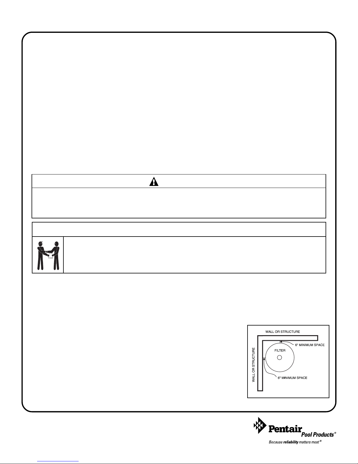
3. Provide sufficient clearance around the filter to permit visual verification
that the clamp is properly installed, see Figure 1.
4. Provide sufficient space above the filter to remove the filter lid for
cleaning and servicing. This distance will vary with the model of filter
you are using. See Table 1, for the required vertical clearance.
Figure 1.
Pentair Water Pool and Spa, Inc.
1620 Hawkins Ave., Sanford, NC 27330 • (800) 831-7133 • (919) 566-8000
10951 West Los Angeles Ave., Moorpark, CA 93021 • (800) 831-7133 • (805) 553-5000
Visit www.pentairpool.com or www.staritepool.com
Rev. D 6-26-09 1 P/N 178556
Page 2
WARNING
Risk of electrical shock or electrocution. Position the filter and High Flow™ manual air relief valve to safely direct water
drainage and purged air or water. Water discharged from an improperly positioned filter or valve can create an
electrical hazard that can cause severe personal injury as well as damage property.
5. When installing the High Flow™ manual air relief
valve use the O-ring only, there is no need for thread
sealing compounds. Position the filter to safely direct
water drainage. Rotate the valve to safely direct
purged air or water. Water discharged from an
improperly positioned filter or valve can create an
electrical hazard as well as damage property.
Model P/N Size Clearance Req.
CC50 160314 50 sq. ft. 30 in.
CC75 160315 75 sq. ft. 39 in.
CC100 160316 100 sq. ft. 61 in.
CC150 160317 150 sq. ft. 76 in.
CC200 160318 200 sq. ft. 76 in.
TABLE 1.
Vertical
6. Make all plumbing connections in accordance with
local plumbing and building codes. Filter plumbing connections are provided with an O-ring seal. Use only
a silicone base lubricant on the O-rings. Do not use pipe joint compound, glue or solvent on the bulkhead
connections.
7. The base of this filter is provided with two (2) mounting bosses for the purpose of anchoring the filter to the
concrete.
8. The maximum working pressure of this filter is 50 psi. Never subject this filter to pressure in excess of this
amount, even when conducting hydrostatic pressure tests. Pressures above 50 psi can cause the lid to be
blown off, which can result in severe injury, death or property damage.
When performing hydrostatic pressure tests or when testing for external leaks of the completed filtration and plumbing
system, ensure that the Maximum Pressure that the filtration system will be subjected to DOES NOT EXCEED
THE MAXIMUM WORKING PRESSURE OF ANY OF THE COMPONENTS CONTAINED WITHIN THE SYSTEM.
In most cases, the maximum pressure will be stated on each component of the system.
If doubt exists as to the pressure to which the system will be subjected, install an ASME approved automatic Pressure Relief
or Pressure Regulator in the circulation system for the lowest working pressure of any of the components in the system.
SECTION II. FILTER OPERATION
THIS FILTER OPERATES UNDER HIGH PRESSURE. WHEN ANY PART OF THE CIRCULATING SYSTEM
(e.g., LOCK RING, PUMP, FILTER, VALVES, ETC.) IS SERVICED, AIR CAN ENTER THE SYSTEM AND
BECOME PRESSURIZED. PRESSURIZED AIR CAN CAUSE THE LID TO BLOW OFF WHICH CAN RESULT
IN SEVERE INJURY, DEATH, OR PROPERTY DAMAGE. TO AVOID THIS POTENTIAL HAZARD, FOLLOW
THESE INSTRUCTIONS.
1. BEFORE REPOSITIONING VALVES AND BEFORE BEGINNING THE ASSEMBLY, DISASSEMBLY, OR ADJUSTMENT OF
THE LOCK RING OR ANY OTHER SERVICE OF THE CIRCULATING SYSTEM: (A) TURN THE PUMP OFF AND SHUT
OFF ANY AUTOMATIC CONTROLS TO ASSURE THE SYSTEM IS NOT INADVERTENTLY STARTED DURING THE
SERVICING; (B) OPEN AIR RELIEF VALVE; AND (C) WAIT UNTIL ALL PRESSURE IS RELIEVED -PRESSURE GAUGE
MUST READ ZERO (0).
2. WHENEVER INSTALLING THE FILTER LOCK RING, FOLLOW THE FILTER LOCK RING INSTALLATION
INSTRUCTIONS EXACTLY.
3. ONCE SERVICE ON THE CIRCULATING SYSTEM IS COMPLETE, FOLLOW SYSTEM RESTART INSTRUCTIONS
EXACTLY.
4. MAINTAIN CIRCULATION SYSTEM PROPERLY. REPLACE WORN OR DAMAGED PARTS IMMEDIATELY (e.g., lock
ring, pressure gauge, relief valve, O-rings, etc.)
5. BE SURE THAT THE FILTER IS PROPERLY MOUNTED AND POSITIONED ACCORDING TO THE INSTRUCTIONS
PROVIDED.
WARNING
P/N 178556 2 Rev. D 6-26-09
Page 3
A. GENERAL INFORMATION
1. This filter operates under pressure. When the lock ring is installed properly and operated without air in
the water system, this filter will operate in a safe manner.
2. The maximum working pressure of this filter is 50 psi. Never subject this filter to pressure in excess of
this amount - even when conducting hydrostatic pressure tests. Pressures above 50 psi can cause the lid
to be blown off, which can result in severe injury, death or property damage.
When performing hydrostatic pressure tests or when testing for external leaks of the completed filtration and
plumbing system, ensure that the Maximum Pressure that the filtration system will be subjected to DOES NOT
EXCEED THE MAXIMUM WORKING PRESSURE OF ANY OF THE COMPONENTS CONTAINED WITHIN
THE SYSTEM. In most cases, the maximum pressure will be stated on each component of the system.
If doubt exists as to the pressure to which the system will be subjected, install an ASME approved automatic Pressure
Relief or Pressure Regulator in the circulation system for the lowest working pressure of any of the components in the
system.
3. The pressure gauge is the primary indicator of how the filter is operating. Maintain your pressure gauge in
good working order.
WARNING
Your filter is a piece of machinery, do not tamper with it, attempt to disassemble it or otherwise adjust it unless you
fully understand it's operation. Serious injury or death can occur if the equipment is improperly handled. Consult a
pool service professional for maintenance and service assistance.
4. Clean your filter when pressure reads between 8-10 psi higher than the original starting pressure. Your
filter pressure reading will increase as it removes dirt from your pool. However, this buildup of pressure
will vary due to different bathing loads, temperature, weather conditions, etc.
a. MY ORIGINAL STARTING PRESSURE IS ___________ psi (pounds per square inch).
I SHOULD CLEAN THE FILTER CARTRIDGES AT __________ psi.
NOTE
When the cartridge element filter is used on new pools and after cleaning the elements, introduce into the system .5 pounds
of diatomaceous earth per every 100 square feet of filter area, (a one-pound coffee can equals .5 pounds of diatomaceous
earth). Mix the diatomite with water and pour it into the skimmer after the pump is primed and the system is operating. This
will enhance the filtration of your water.
B. LOCK RING INSTALLATION INSTRUCTIONS
These instructions MUST BE FOLLOWED EXACTLY to prevent the lid from blowing off during system restart or
later operation.
1. Perform the following steps before working on any part of the circulating system (e.g., lock ring, pump,
filter, valves, etc.).
a. Turn the pump off and shut off any automatic controls to ensure that the system is not
inadvertently started during servicing.
b. Open the High Flow™ manual air relief valve.
c. Wait until all pressure is relieved. Never attempt to assemble, disassemble or adjust the
filter lock ring while there is any pressure in the filter.
Rev. D 6-26-09 3 P/N 178556
Page 4

WARNING
THIS FILTER OPERATES UNDER HIGH PRESSURE. WHEN ANY PART OF THE CIRCULATING SYSTEM (e.g., LOCK
RING, PUMP, FILTER, VALVES, ETC.) IS SERVICED, AIR CAN ENTER THE SYSTEM AND BECOME PRESSURIZED.
PRESSURIZED AIR CAN CAUSE THE LID TO BE BLOWN OFF WHICH CAN RESULT IN SEVERE INJURY, DEATH, OR
PROPERTY DAMAGE. TO AVOID THIS POTENTIAL HAZARD, FOLLOW THESE INSTRUCTIONS.
2. Be certain the O-ring is in position in the lower tank half. Place the filter lid over the lower tank half,
making sure it is fully and firmly seated on the tank half, see Figure 2.
3. Place lock ring over the tank lid, and centering the lock ring on the threads of the tank body. Turn the
lock ring clockwise until the safety latches click and the lock ring hits the stops on the body. DO
NOT ATTEMPT TO OVER-TIGHTEN THE LOCK RING AFTER LOCK RING HAS HIT THE
STOPS ON THE BODY.
4. Follow the System Restart Instructions in Section C.
C. SYSTEM RESTART INSTRUCTIONS
WARNING
THIS FILTER OPERATES UNDER HIGH PRESSURE. WHEN ANY PART OF THE CIRCULATING SYSTEM (e.g., LOCK
RING, PUMP, FILTER, VALVES, ETC.) IS SERVICED, AIR CAN ENTER THE SYSTEM AND BECOME PRESSURIZED.
PRESSURIZED AIR CAN CAUSE THE LID TO BE BLOWN OFF WHICH CAN RESULT IN SEVERE INJURY, DEATH, OR
PROPERTY DAMAGE. TO AVOID THIS POTENTIAL HAZARD, FOLLOW THESE INSTRUCTIONS.
1. Open the High Flow™ manual air relief valve until it snaps into the full open position (this only
requires a quarter turn counterclockwise). Opening this valve rapidly releases air trapped in the filter.
2. Stand clear of the filter tank, then start the pump.
3. Close the High Flow™ manual air relief valve after a steady stream of water
appears.
Filter
Ta nk
To p
4. The system is not working properly if either of the following conditions occur.
a. A solid stream of water does not appear within 30 seconds, after the
Lock
Ring
pump's inlet basket fills with water.
Filter
b. The pressure gauge indicates pressure before water outflow appears.
Ta nk
Body
If either condition exists, shut off the pump immediately, open valves in the water
return line to relieve pressure, and clean the air relief valve, see Section F. Cleaning
the High Flow™ manual air relief valve. If the problem persists, call (800) 831-7133 for
assistance.
Figure 2.
D. CLEANING THE FILTER
WARNING
The following information should be read carefully since it outlines the proper manner of care and operation for your filter system.
As a result of following these instructions and taking the necessary preventative care, you can expect maximum efficiency and
life from your filter system.
Please heed all manufacturers' posted instructions, warnings and cautions when using Baquacil® or Baqua
Clean.
1. Turn the pump off, shut off any automatic controls to ensure that the system is not inadvertently started
during servicing.
P/N 178556 4 Rev. D 6-26-09
CAUTION
®
Page 5

2. Open the filter High Flow™ manual air relief valve, (and the waste drain valve, or cap, if your system
has one).
NOTE
Special care must be taken when cleaning cartridge element used in a swimming pool or spa using Baquacil® as a sanitizer.
Because of the way Baquacil
chlorine system. If extreme care is not taken to completely remove all residue from the cartridge element, a buildup will
occur. This buildup will significantly shorten the life of the cartridge element.
Baquacil
bathers, etc. into particles large enough to be trapped by the filter. In comparison with all other trapped contaminants in a
typical pool or spa the amount of bacterial cells that are deposited on the filter is minimal. The resulting deposit is a gray
sticky film which can only be removed with Baqua
the cleaner and the gray film will combine to form a gum-like substance. Once this occurs, the substance cannot be removed
from the media and the cartridge element must be replaced.
®
is a mild coagulant which combines bacterial cells as well as other small particles contributed by the environment,
®
works, the cartridge element must be cleaned more thoroughly and more frequently than in a
®
Clean. If TSP or any TSP type cleaner is used prior to stripping the film,
3. Remove hair and lint strainer pot lid and clean basket. Replace basket and secure lid.
4. Disconnect air relief drain hose if installed.
5. Remove locking ring by depressing safety latches on both sides of ring and rotate counterclockwise, then
remove tank lid.
6. Remove the element assembly by placing hands in lifting handles and pulling straight up on the element
assembly.
7. Remove the cartridge element from the center support tube.
8. Using a garden hose with a nozzle, direct water spray at the cartridge element to dislodge and wash away
accumulated foreign matter. Water may be sprayed at the outside as well as the inside of the cartridge
element for thorough cleaning.
9. Turn the cartridge element over several times during the washing operation to clean the media
thoroughly.
10. Clean and remove debris from inside the filter tank and from the O-ring and O-ring groove on the tank
body.
11. Replace clean cartridge element on support tube and install assembly into the filter tank body, aligning
the arrow on the support tube with the inlet port of the filter, making sure it is fully seated. Make sure
the internal air relief screen is attached to the top of the element support tube.
12. Replace the tank lid onto the tank body making sure it is fully and firmly seated on the tank body.
13. Place lock ring over tank lid, and centering the lock ring on the threads of the tank body, turn the lock
ring clockwise until the safety latches click and the lock ring hits the stops on the body. DO NOT
ATTEMPT TO OVER-TIGHTEN THE LOCK RING AFTER LOCK RING HAS HIT THE STOPS
ON THE BODY.
NOTE
Any time the filter tank is opened, and/or element assembly is removed, be sure to generously coat the O-ring with silicone
lubricant before reassembling the unit. DO NOT USE PETROLEUM BASED LUBRICANTS BECAUSE THEY HAVE A
DETERIORATING EFFECT ON RUBBER.
14. Replace drain cap and reinstall High Flow™ manual air relief valve drain hose if used.
E. REPLACING CARTRIDGE ELEMENT
Cartridge element life will vary with pool conditions such as bather load, wind, dust, etc. You can expect an average
media life of three (3) years under normal conditions.
1. To replace cartridge element follow steps in section D, Cleaning the Filter.
Rev. D 6-26-09 5 P/N 178556
Page 6

F. CLEANING THE HIGH FLOW™ MANUAL AIR RELIEF
VALVE
1. Turn the pump off and shut off any automatic controls to ensure
that the system is not inadvertently started during servicing.
2. OPEN THE HIGH FLOW™ MANUAL AIR RELIEF
VALVE UNTIL IT SNAPS INTO THE FULL OPEN
POSITION, THEN WAIT UNTIL ALL PRESSURE IS
RELIEVED.
3. With the relief valve attached to the filter tank, pull out the
locking tabs and remove the valve stem and cover assembly with
a counterclockwise and lifting motion, see Figure 3.
4. Clean debris from the valve stem and body. Verify that the filter
tank's air passage is open by inserting a 5/16 in. drill bit through
the valve body. Verify that the O-ring are in good condition,
properly positioned, and lubricated with a silicone base lubricant.
5. Reinstall the valve stem and cover assembly with a downward
and clockwise motion until it snaps into position.
Figure 3.
SECTION III. TROUBLESHOOTING
A. Air entering your filter is dangerous and can cause the lid to blow off. Correct any conditions in your
filtration system that allow air to enter the system.
1. Some common ways to identify air entering the system:
a. Low water level in pool or spa - skimmer is starving for water with pump running. Add water to
pool or spa.
b. Air bubbles or low water level in pump hair and lint pot are caused by; low water level, clogged
skimmer basket, split suction cleaner hose, leak in pump hair and lint pot lid, or leak in pump
suction line.
c. Air bubbles coming out of water return lines into pool or spa with pump running, see items 1.a
and 1.b of this section.
d. Air is discharged from the air relief valve on top of the filter when the valve is opened with the
pump running, see items 1.a and 1.b of this section, above.
B. Until the water initially put into the pool has been completely filtered, short filter cycles in between
cleanings are normal. In most cases pool owners are dismayed by the undesirable color and appearance
of water in a newly filled pool. Plaster dust can be responsible for short filter cycles, requiring frequent
cleaning.
C. If pressure drops on gauge, check skimmer basket and pump basket first for debris. If the baskets are
clean, shut off power to pump and turn off any automatic controls. Then turn motor shaft with your
fingers. If it turns freely then the pump must be disassembled and the impeller checked to see if it is
clogged. If it is not frozen or clogged then there is an obstruction in the line between the pool and the
pump.
D. The pressure gauge is an important part of the filter system. It is your primary indicator of how the
system is operating. Maintain your pressure gauge in good working order. Check the operation of your
pressure gauge in the following manner:
1. The pressure gauge should go to zero (0) when the system is turned off and pressure is relieved.
2. The pressure gauge should indicate pressure when the system is operating.
3. The pressure gauge should be readable and not damaged in any way.
4. Replace the pressure gauge if it is not meeting the requirements of items D.1 through D.2 of this section,
above.
P/N 178556 6 Rev. D 6-26-09
Page 7

SECTION IV. TECHNICAL DATA
A. Filter Pressure Loss Chart
9
8
7
6
5
4
3
PRESSURE LOSS (psi)
2
1
0
020406080100120140
PRESSURE LOSS vs FLOW
FLOW (gpm)
C. Replacement Parts
B. Flow Rate Table
laitnediseR
egdirtraCmumixaM
setaRwolF
#tcudorP.tf.qsMPGHPGruoh6ruoh8MPGHPGruoh6ruoh8
4130610505000,3000,81000,4291041,1048,6021,9
5130615757005,4000,72000,6382086,1080,01044,31
613061001001000,6000,63000,8483082,2086,31042,81
713061051051000,9000,45000,2765063,3061,02088,62
813061002051000,9000,45000,2757005,4000,72000,63
(1) One GPM per sq. ft. shown, recommended flow rate for residential is .5 GPM per sq. ft.
(2) Commercial flow rate is a maximum of .375 GPM per sq. ft. of filter area.
NOTE: Actual system flow will depend on plumbing size and other system components.
2
1
laicremmoC
setaRwolF
egdirtraCmumixaM
Item Part Number Description
198209800High Flow
™
manual air relief valve
2190058Pressure Gauge
3178553Lid, 50, 100 sq. ft. filter
4178561Lid, 75,150, 200 sq. ft. filter
559052900Locking Ring assy.
687300400Body O-ring
759016200Air Bleed Sock Kit
859053500Center Core, 50 sq. ft. filter
959053600Center Core, 75 sq. ft. filter
10 59053700 Center Core, 100 sq. ft. filter
11 59053800 Center Core, 150, 200 sq. ft. filter
12 R173213 Cartridge Element, 50 sq. ft. filter
13 R173214 Cartridge Element, 75 sq. ft. filter
14 R173215 Cartridge Element, 100 sq. ft. filter
15 R173216 Cartridge Element, 150 sq. ft. filter
16 R173217 Cartridge Element, 200 sq. ft. filter
17 178562 Bottom, 50 sq. ft. filter
18 178554 Bottom, 75 sq. ft. filter
19 178563 Bottom, 100 sq. ft. filter
20 178560 Bottom, 150, 200 sq. ft. filter
21 86202000 Drain Cap Assy.
22 51005000 Drain Cap Gasket
23 39104500 Union Nut “C” Clip
24 98212200 Union Nut
25 071426 Union O-ring
26 79304600 Body, Swivel
3, 4
5
6
7
8, 9, 10, 11
12, 13, 14, 15, 16
17, 18, 19, 20
21, 22
25
26
Rev. D 6-26-09 7 P/N 178556
24
23
Page 8

SAVE THESE INSTRUCTIONS
© 2009 Pentair Water Pool and Spa, Inc. All rights reserved.
1620 Hawkins Ave., Sanford, NC 27330 • (800) 831-7133 • (919) 566-8000
10951 West Los Angeles Ave., Moorpark, CA 93021 • (800) 831-7133 • (805) 553-5000
This document is subject to change without notice.
Trademarks and Disclaimers: Pentair Pool Products®, Because reliability matters most®, Clean & Clear®, and High Flow™, are trademarks and/or registered trademarks of Pentair
Water Pool and Spa, Inc. and/or its affiliated companies in the United States and/or other counties. Baquacil® and Baqu a® are registered tradem arks of Ar ch UK Biocides Limited.
Unless noted, names and brands of others that may be used in this document are not used to indicate an affiliation or endorsement between the proprietors of these names and brands
and Pentair Water Pool and Spa, Inc. Those names and brands may be the trademarks or registered trademarks of those parties or others.
P/N 178556 8 Rev. D 6-26-09
 Loading...