

Pentair Berkeley BPD Series, Berkeley BPDH15-L, Berkeley BPDH10-L, Berkeley BPDH25-L, Berkeley BPDH20-L Owner's Manual

owner's Manual
Corrosion Resistant
Self-Priming Centrifugal Pump
P
5
3
-
6
7
1
L
BPD
Installation/Operation/Parts
For further operating, installation, or maintenance assistance:
Call 1-888-782-7483
293 WRIGHT STREET, DELAVAN, WI 53115 WWW.BERKELEYPUMPS.COM
PH: 888-782-7483
© 2013 Pentair, Ltd. All Rights Reserved. BE190 (Rev. 02/22/13)
Safety 2
READ AND FOLLOW
SAFETY INSTRUCTIONS!
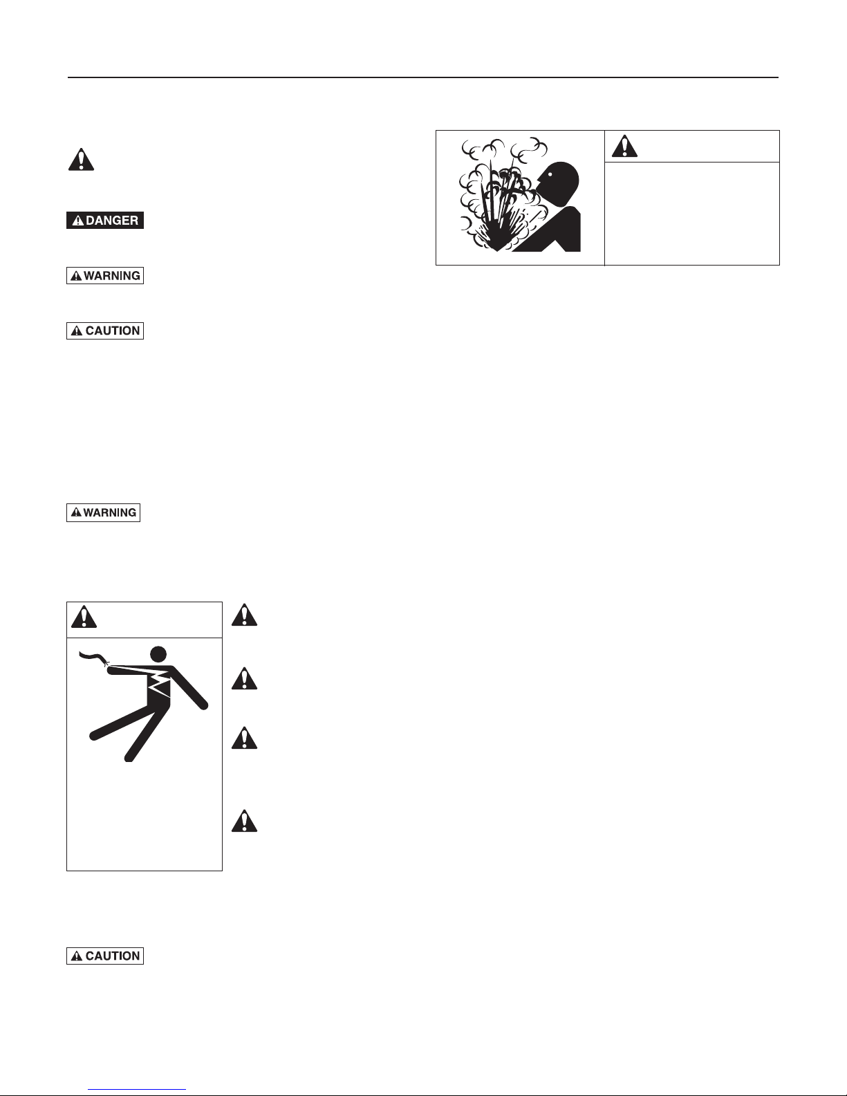
This is the safety alert symbol. When you see this
symbol on your pump or in this manual, look for
one of the following signal words and be alert to the
potential for personal injury:
warns about hazards that will cause serious
personal injury, death or major property damage if
ignored.
personal injury, death or major property damage if
ignored.
minor personal injury or property damage if ignored.
The label NOTICE indicates special instructions which
are important but not related to hazards.
Carefully read and follow all safety instructions in this
manual and on pump.
Keep safety labels in good condition.
Replace missing or damaged safety labels.
California Proposition 65 Warning
chemicals known to the State of California to cause
cancer, birth defects or other reproductive harm.
warns about hazards that can cause serious
warns about hazards that will or can cause
This product and related accessories contain
GENERAL SAFETY
WARNING
Hazardous pressure!
Do not run pump against
closed discharge.
Release all pressure on
system before working on
any component.
Pump is designed as a lawn sprinkler only. To avoid heat
built-up, over pressure hazard and possible injury, do not
use in a pressure tank (domestic water) system. Do not use
as a booster pump; pressurized suction may cause pump
body to explode.
Do not allow pump or piping system to freeze. Freezing
can damage pump and pipe, may lead to injury from
equipment failure and will void warranty.
Pump water only with this pump.
Periodically inspect pump and system components.
Wear safety glasses at all times when working on pumps.
Keep work area clean, uncluttered and properly lighted;
store properly all unused tools and equipment.
Keep visitors at a safe distance from the work areas.
ELECTRICAL SAFETY
Wire motor for correct
WARNING
Hazardous voltage.
Can shock, burn, or
cause death.
Ground pump before
connecting to power
supply.
Make workshops childproof; use padlocks and master
switches; remove starter keys.
Do not touch an operating motor. Modern
motors are designed to operate at high temperatures. To
avoid burns when servicing pump, allow it to cool for 20
minutes after shut-down before handling.
voltage. See “Electri cal”
section of this manual
and motor nameplate.
Ground motor before
connecting to power
supply.
Meet National Electri cal
Code, Canadian Elec trical Code, and local
codes for all wiring.
Follow wiring
instructions in this
manual when
connecting motor to
power lines.

Table of Contents 3
Thank you for purchasing a top quality, factory tested pump.
Page
General Safety .....................................................................................................2
Warranty..............................................................................................................3
Installation ........................................................................................................4-6
Electrical ...........................................................................................................7,8
Operation ............................................................................................................9
Maintenance .................................................................................................10-12
Troubleshooting .................................................................................................13
Repair Parts .................................................................................................14,15
Limited Warranty
BERKELEY warrants to the original consumer purchaser (“Purchaser” or “You”) of the products listed below, that they will be free
from defects in material and workmanship for the Warranty Period shown below.
Product Warranty Period
Water Systems:
Water Systems Products — jet pumps, small centrifugal pumps, submersible pumps and
related accessories
Pro-Source™ Composite Tanks 5 years from date of original installation
Pro-Source™ Steel Pressure Tanks 5 years from date of original installation
Pro-Source™ Epoxy-Lined Tanks 3 years from date of original installation
Sump/Sewage/Effluent Products
Agricultural/Commercial:
Centrifugals – close-coupled motor drive, frame mount, SAE mount, engine drive, VMS, SSCX,
SSHM, solids handling, submersible solids handling
Submersible Turbines, 6” diameter and larger
Our limited warranty will not apply to any product that, in our sole judgement, has been subject to negligence, misapplication,
improper installation, or improper maintenance. Without limiting the foregoing, operating a three phase motor with single phase
power through a phase converter will void the warranty. Note also that three phase motors must be protected by three-leg,
ambient compensated, extra-quick trip overload relays of the recommended size or the warranty is void.
Your only remedy, and BERKELEY’s only duty, is that BERKELEY repair or replace defective products (at BERKELEY’s choice). You
must pay all labor and shipping charges associated with this warranty and must request warranty service through the installing
dealer as soon as a problem is discovered. No request for service will be accepted if received after the Warranty Period has
expired. This warranty is not transferable.
BERKELEY SHALL NOT BE LIABLE FOR ANY CONSEQUENTIAL, INCIDENTAL, OR CONTINGENT DAMAGES WHATSOEVER.
THE FOREGOING LIMITED WARRANTIES ARE EXCLUSIVE AND IN LIEU OF ALL OTHER EXPRESS AND IMPLIED WARRANTIES,
INCLUDING BUT NOT LIMITED TO IMPLIED WARRANTIES OF MERCHANTABILITY AND FITNESS FOR A PARTICULAR
PURPOSE. THE FOREGOING LIMITED WARRANTIES SHALL NOT EXTEND BEYOND THE DURATION PROVIDED HEREIN.
Some states do not allow the exclusion or limitation of incidental or consequential damages or limitations on the duration of an
implied warranty, so the above limitations or exclusions may not apply to You. This warranty gives You specific legal rights and You
may also have other rights which vary from state to state.
This Limited Warranty is effective June 1, 2011 and replaces all undated warranties and warranties dated before June 1, 2011.
whichever occurs first:
12 months from date of original installation, or
18 months from date of manufacture
12 months from date of original installation, or
18 months from date of manufacture
12 months from date of original installation, or
24 months from date of manufacture
12 months from date of original installation, or
24 months from date of manufacture
In the U.S.: BERKELEY, 293 Wright St., Delavan, WI 53115
In Canada: 269 Trillium Dr., Kitchener, Ontario N2G 4W5
Installation 4
Use PTFE tape.
Use PTFE pipe thread sealant tape or pipe joint
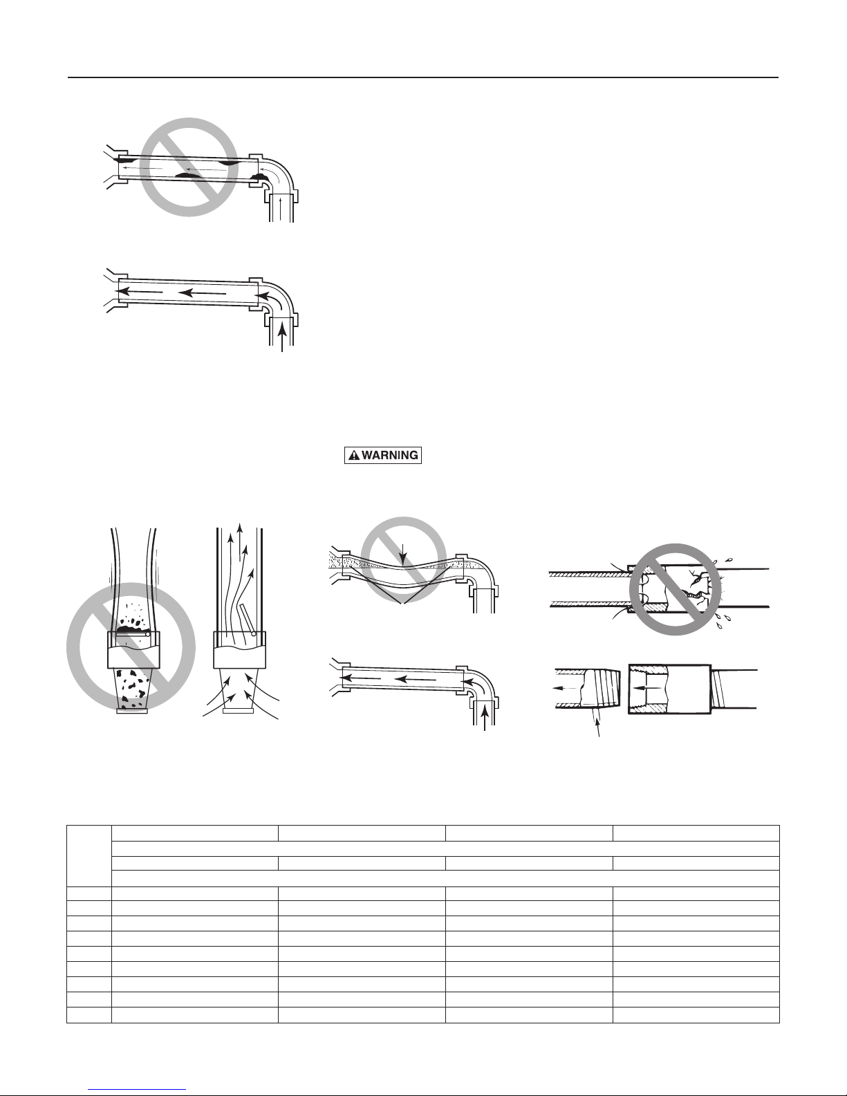
Dirt and Scale Plug Pump and Pipes!
Use New Pipe for Best Results.
Pump
Body
Clean Flow!
From
Well
Figure 1 – No Dirt or Scale in Suction
Pipe
BEFORE YOU INSTALL YOUR PUMP
NOTICE: Well must not be more than 20' depth to water.
1. Long runs and many fittings increase friction and reduce flow. Locate
pump as close to well as possible: use as few elbows and fittings as
possible.
2. Be sure well is clear of sand. Sand will plug the pump and void the
warranty.
3. Protect pump and all piping from freezing. Freezing will split pipe,
damage pump and void the warranty. Check locally for frost protection
requirements (usually pipe must be 12" below frost line and pump must
be insulated).
4. Be sure all pipes and foot valve are clean and in good shape.
5. No air pockets in suction pipe.
6. No leaks in suction pipe. Use PTFE pipe thread sealant tape to seal pipe
joints.
7. Unions installed near pump and well will aid in servicing. Leave room
to use wrenches.
8.
DO NOT use in a booster appli cation.
NOTICE: Use the installation method below which matches your well type.
Pump body may explode if used as a booster pump.
compound approved for use on PVC.
1100 0697
Figure 2 – Foot Valve Must Work
Freely
No Sags
Sags Allow Air Pockets
If Air Pockets Form, Water Won’t Flow.
Keep Pipe Straight and Angled up to Pump.
Figure 3 – No Air Pockets in Suction
Pipe
No air leaks In
Suction pipe.
If air flows
water won’t
Figure 4 – Suction Pipe Must Not Leak
PERFORMANCE CHART (in gallons per minute) – High Head
BPDH10-L BPDH15-L BPDH20-L BPDH25-L
Disch. Distance Above Water
Press
5' 10' 15' 20' 5' 10' 15' 20' 5' 10' 15' 20' 5' 10' 15' 20'
PSI
Capacity – Gallons Per Minute
10 55 49 48 45 67 61 56 46 69 67 65 62 92 83 81 78
15 51 46 45 44 66 58 55 45 65 63 60 58 86 79 78 76
20 45 42 39 37 61 56 54 44 59 56 54 52 80 76 75 74
25 38 35 32 29 55 52 51 43 52 50 48 45 73 71 70 69
30 31 28 24 20 48 45 44 38 47 45 42 40 66 66 65 64
35 23 19 16 11 39 37 34 28 42 38 35 32 60 60 59 58
40 17 13 8 33 27 20 11 34 30 27 23 55 54 53 52
45 18 14 8 25 17 10 47 46 46 45
50 14 7 40 38 37 36
Models BPDH10-L and BPDH15-L have 2" NPT suction and 1-1/2” NPT discharge.
Models BPDH20-L and BPDH25-L have 2" NPT suction and discharge.
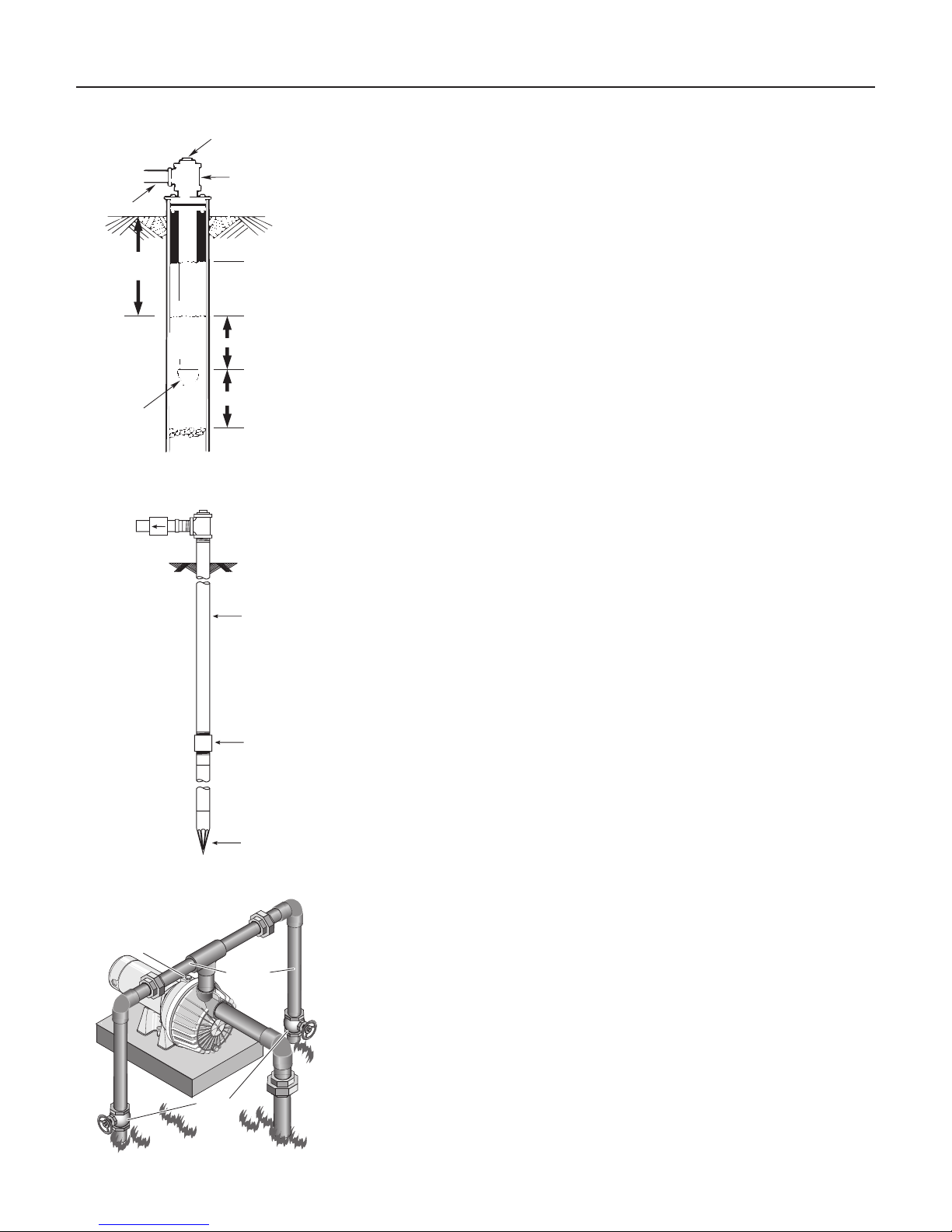
Installation 5
Priming plug
828 0993
CASED WELL INSTALLATION
Priming tee
Suction
pipe
20' (6 m) max.
Foot
Valve
Standing water
level (pump off)
Drawdown water
level (pump on)
10-20' (3-6 m)
At least 5 feet (1.5 m)
Figure 5 – Cased/Dug Well Installation
Check valve
Steel drive pipe
1. Inspect foot valve to be sure it works freely. Inspect strainer to be sure it
is clean.
2. Connect foot valve and strainer to the first length of suction pipe and
lower pipe into well. Add sections of pipe as needed, using PTFE pipe
thread sealant tape on male threads. Be sure that all suction pipe is
leakproof or pump will lose prime and fail to pump. Install foot valve
10 to 20 feet below the lowest level to which water will drop while
pump is operating (pumping water level). Your well driller can furnish
this in formation.
3. To prevent sand and sediment from entering the pumping system, the
foot valve/strainer should be at least 5 feet above the bottom of the well.
4. When the proper depth is reached, install a sanitary well seal over the
pipe and in the well casing. Tighten the bolts to seal the casing.
5. When using a foot valve, a priming tee and plug as shown in Figure 5
are recommended.
DUG WELL INSTALLATION
Same as cased well installation.
DRIVEN POINT INSTALLATION
1. Connect the suction pipe to the drive point as illustrated in Figure 6.
Keep horizontal pipe run as short as possible. Use PTFE pipe thread
sealant tape on male pipe threads. Multiple well points may be
necessary to provide sufficient water to pump.
2. Install a check valve in horizontal pipe. Flow arrow on check valve
must point toward pump.
Drive coupling
Driven point
Figure 6 – Driven Point Installation
Priming
Plug
P
To
Service
Gate
Valve
Figure 7 – Multiple Discharge
HORIZONTAL PIPING FROM WELL TO PUMP
1. Never install a suction pipe that is smaller than the suction port of the
pump.
2. To aid priming on well point installations, install a line check valve as
shown in Figure 6. Be sure check valve flow arrow points toward pump.
DISCHARGE PIPE SIZES
1. If increasing discharge pipe size, install reducer in pump discharge port.
Do not increase pipe size by stages.
2. When the pump is set away from the points of water use, the discharge
pipe size should be increased to reduce pressure losses caused by
friction.
•Upto100'run:Samesizeaspumpdischargeport.
•100'to300'run:Increaseonepipesize.
•300'to600'run:Increasetwopipesizes.
LAWN SPRINKLING APPLICATION
This pump is designed for lawn sprinkling. It is de signed to deliver plenty
of water at full sprinkler pres sure. It can pump from a pond, cistern or well
points.
Pump discharge can be divided to supply two (2) or more sprinkler
systems. A suggested multiple dis charge to service is shown in Figure 7.
Installation 6
532 1193
530 1193
748 0993
F
Do not use in a pressure tank or booster pump application.
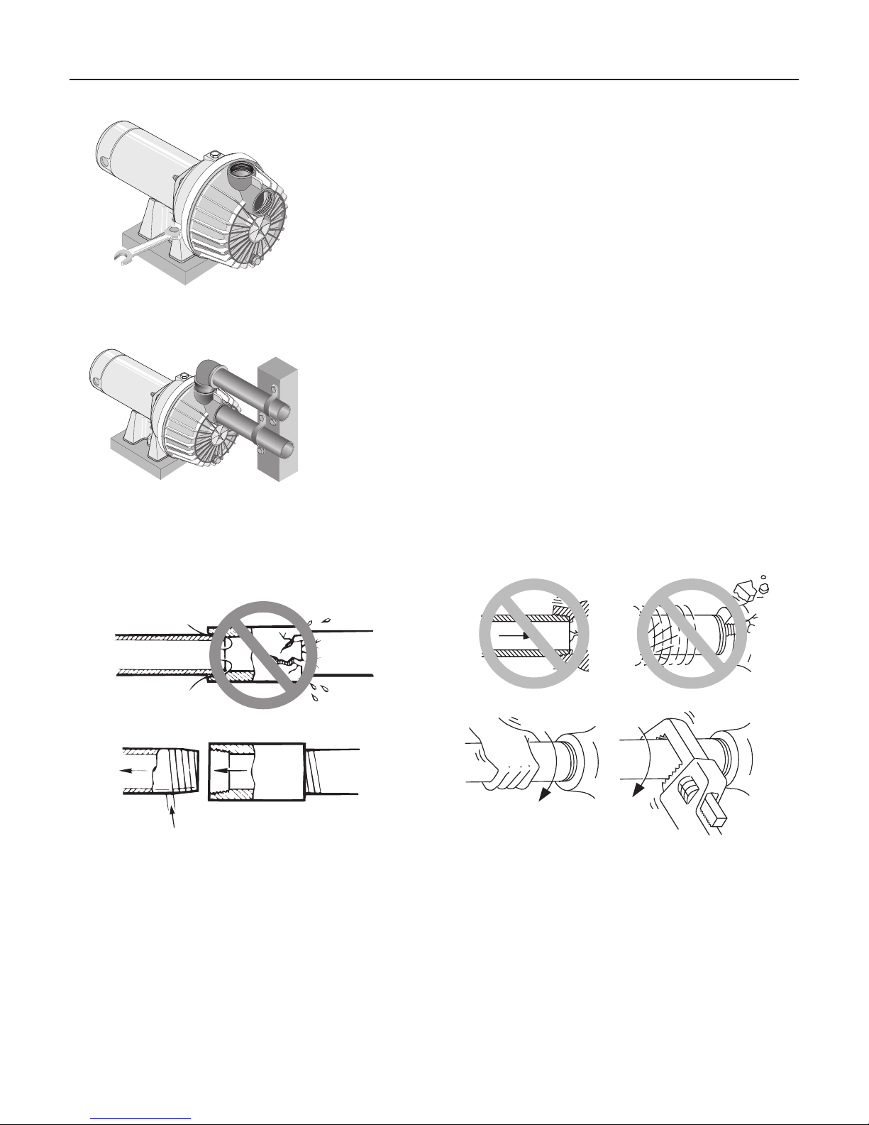
PUMP INSTALLATION
P
Figure 8 – Bolt Pump Down
P
Figure 9 – Independently Support All
Piping Attached to Pump
NOTICE: Use only PTFE pipe thread sealant tape for making all threaded
connections to the pump itself. Do not use pipe joint compounds on
plastic pumps: they can react with the plastic in the pump components.
Make sure that all pipe joints in the suction pipe are air tight as well as
water tight. If the suction pipe can suck air, the pump will not be able to
pull water from the well.
1. Bolt pump to solid, level foundation.
2. Support all piping connected to the pump.
3. Wrap 1-1/2 to two layers of PTFE pipe thread sealant tape clockwise (as
you face end of pipe) on all male threads being attached to pump.
4. Tighten joints hand tight plus 1-1/2 turns. Do not overtighten.
NOTICE: Install pump as close to well head as poss ible. Long piping runs
and many fittings create friction and reduce flow.
NOTICE: For long horizontal pipe runs, install a priming tee between
check valve and well head as shown in Figure 6. For driven point
installations, install a check valve as shown in Figure 6. Be sure check
valve flow arrow points toward pump.
Use schedule 80 or iron pipe. See “Well Pipe In stalla tion” for more
information.
Use PTFE pipe thread sealant tape or pipe joint
compound approved for use on PVC.
No air leaks In
Suction pipe.
If air flows
water won’t
Use PTFE tape.
Figure 10 – Use PTFE pipe thread sealant tape on pipe
Don’t Hit
Thread Stops
rom
Well
Hand Tight Plus 1-1/2 Tu rns With Wrench.
Pump
Body
Figure 11 – Don’t overtighten.
Don’t
Overtighten
joints and connections to pump.
Electrical 7
Connection diagram for dual voltage, single-phase motors. Your dualvoltage motor’s terminal board (under the motor end cover) will match one
of the diagrams below. Follow that diagram if necesary to convert motor to
115 Volt power.
Connect power supply wires to L1 and L2. For 3-phase motors, or if motor
does not match these pictures, follow the connection diagram on the motor
nameplate.
Hazardous voltage. Can shock, burn, or cause death.
Disconnect power to motor before working on pump or motor. Ground
motor before con necting to power supply.
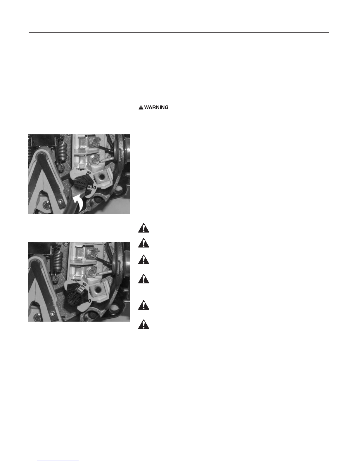
THE MOTOR IS SET FOR
230 VOLTS WHEN SHIPPED.
To change the motor to use 115 volts:
1. Turn off power
2. Remove the back motor cover.
3. Use a screwdriver or 1/2” wrench and turn the voltage selector dial
counterclockwise until 115 shows in the dial opening.
4. Reinstall the motor cover.
Figure 12 - Changing the Voltage
Setting
Figure 13 – Motor Set for 115 Volt
Operation
WIRING
Ground motor before connecting to electrical power supply. Failure to
ground motor can cause severe or fatal electrical shock hazard.
Do not ground to a gas supply line.
To avoid dangerous or fatal electrical shock, turn OFF power to motor
before working on electrical connections.
Supply voltage must be within ±10% of nameplate voltage. Incorrect
voltage can cause fire or damage motor and voids warranty. If in doubt
consult a licensed electrician.
Use wire size specified in Wiring Chart (Page 8). If possible, connect
pump to a separate branch circuit with no other appliances on it.
Wire motor according to diagram on motor nameplate. If nameplate
diagram differs from diagrams above, follow nameplate diagram.

Electrical 8
1. Install, ground, wire and maintain this pump in accordance with
electrical code requirements. Consult your local building inspector for
information about codes.
2. Provide a correctly fused disconnect switch for protection while
working on motor. Consult local or national electrical codes for switch
requirements.
3. Disconnect power before servicing motor or pump. If the disconnect
switch is out of sight of pump, lock it open and tag it to prevent
unexpected power appli cation.
4. Ground the pump permanently using a wire of the same size as that
specified in wiring chart (below). Make ground connection to green
grounding term inal under motor canopy marked GRD. or .
5. Connect ground wire to a grounded lead in the service panel or to a
metal underground water pipe or well casing at least 10 feet long. Do
not connect to plastic pipe or insulated fittings.
6. Protect current carrying and grounding conductors from cuts, grease,
heat, oil, and chemicals.
7. Connect current carrying conductors to terminals L1 and L2 under
motor canopy. When replacing motor, check wiring diagram on motor
nameplate against Figure 12. If the motor wiring diagram does not
match either diagram in Figure 12, follow the dia gram on the motor.
IMPORTANT: 115/230 Volt single phase models are shipped from factory
with motor wired for 230 volts. If power supply is 115 volts, remove motor
canopy and reconnect motor as shown in Figure 12. Do not try to run
motor as received on 115 volt current.
8. Motor has automatic internal thermal overload protection. If motor has
stopped for unknown reasons, thermal overload may restart it unexpectedly, which could cause injury or property damage. Disconnect
power before servicing motor.
9. If this procedure or the wiring diagrams are con fusing, consult a
licensed electrician.
Wiring Chart – Recommended Wire and Fuse Sizes
Motor
Model HP Volts Amp Amp AWG WIRE SIZE (mm
BPDH10-L 1 115/230 14.8/7.4 20/15 12/14(3/2) 8/14(8.4/2) 6/14(14/2) 6/12(4/3) 4/10(21/5.5)
BPDH15-L 1-1/2 115/230 19.2/9.6 25/15 10/14(5.5/2) 8/14(8.4/2) 6/12(14/3) 4/10(21/5.5) 4/10(21/5.5)
BPDH20-L 2 115/230 24.0/12.0 30/15 10/14(5.5/2) 6/14(14/2) 6/12(14/3) 4/10(21/5.5) 4/10(21/5.5)
BPDH25-L 2-1/2 115/230 26.0/12.0 30/15 8/14(8.4/2) 6/14(14/2) 6/12(14/3) 4/10(21/5.5) 4/10(21/5.5)
Max.
Load
DISTANCE IN FEET(METERS) FROM MOTOR TO SUPPLY
Branch
0 - 100 101 - 200 201 - 300 301 - 400 401 - 500
Fuse
(0 - 30) (31 - 61) (62 - 91) (92 - 122) (123 - 152)
Rating
2
)
Operation 9
PRIMING THE PUMP
NOTICE: ‘Priming’ refers to the pump expelling all air in the system and
beginning to move water from its source out into the system. It does not
refer only to pouring water into the pump (although pouring water in is
usually the first step).
NOTICE: NEVER run pump dry. Running pump with out water in it will
damage seals and can melt impeller and diffuser. To prevent damage, fill
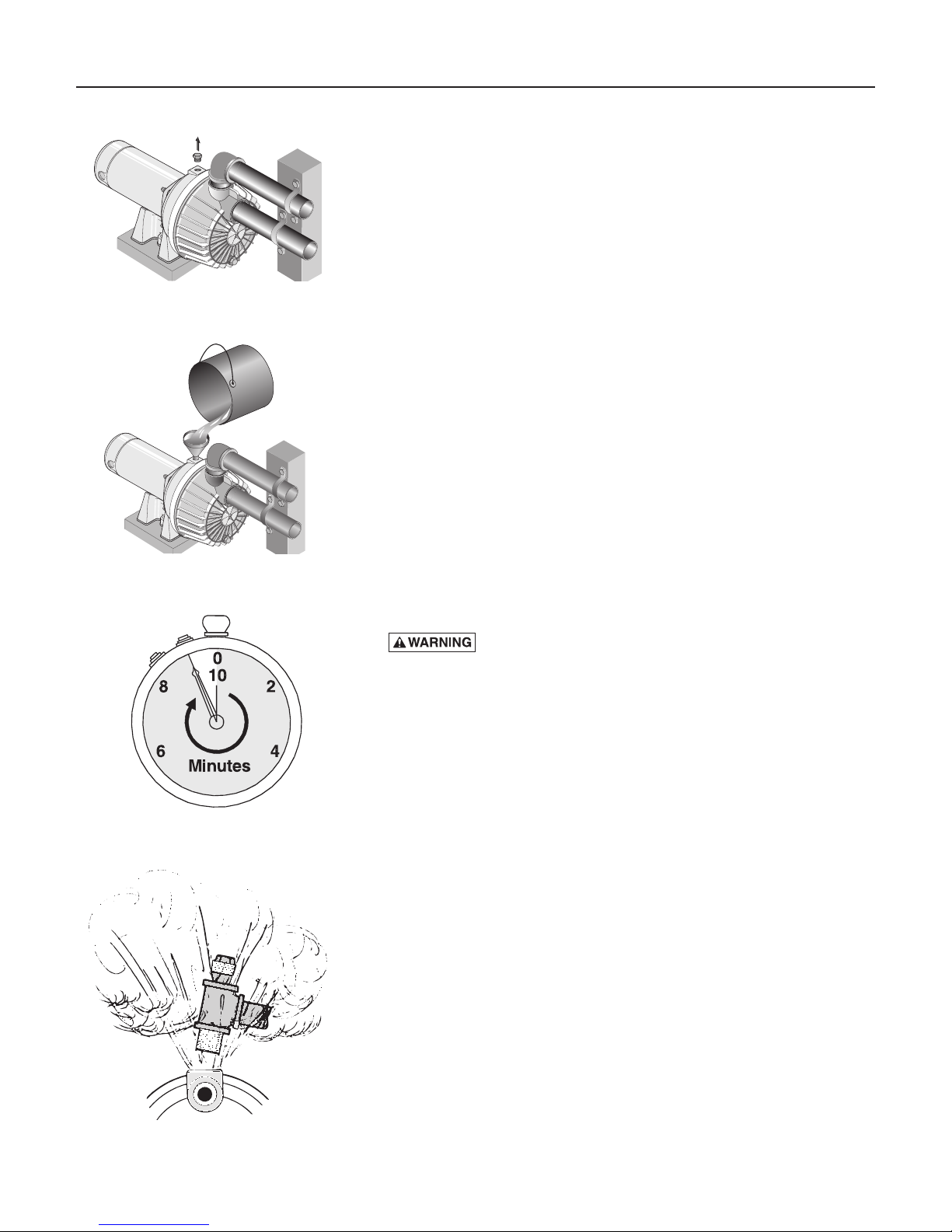
Figure 14 – Remove Priming Plug
P
Figure 15 – Fill Pump Before Starting
pump with water before starting.
1. Remove priming plug (Figure 14).
2. Make sure suction and discharge valves and any hoses on discharge side
of pump are open.
3. Fill pump and suction pipe with water.
4. Replace priming plug, using PTFE pipe thread sealant tape on thread;
tighten plug.
NOTICE: If a priming tee and plug have been provided for a long
horizontal run, be sure to fill suction pipe through this tee and replace
plug. (Don’t forget to tape the plug.)
5. Start pump: water should be produced in 10 minutes or less, the
time depending on depth to water (not more than 20') and length of
horizontal run (10' of horizontal suction pipe = 1' of vertical lift due to
friction losses in the pipe).
If no water is produced within 10 minutes, stop pump, release all
pressure, remove priming plug, refill and try again.
Figure 16 – Run Ten Minutes or Less
Hazardous pressure and risk of ex plo sion and scalding. If
pump is run con ti nu ously at no flow (that is, with discharge shut off or
without priming), water may boil in pump and piping system. Under
steam pressure, pipes may rupture, blow off of fittings or blow out of
pump ports and scald anyone near.
To prevent explosion, do the following:
A. Be sure discharge (valve, pistol grip hose nozzle, etc.) is open whenever
pump is running.
B. If pump fails to produce water when attempting to prime, release
all pressure, drain pump and refill with cold water after every two
attempts.
C. When priming, monitor pump and piping tempera ture. If pump or
piping begin to feel warm to the touch, shut off pump and allow system
to cool off. Release all pressure in system and refill pump and piping
with cold water.
Figure 17 – Do Not Run Pump with
Discharge Shut-off
Maintenance 10
754 0993
542 1193
MAINTENANCE
Pump and piping need not be disconnected to repair or replace motor or
seal (see Figure 19). If motor is replaced, replace the shaft seal. Keep one
on hand for future use.
Be sure to prime pump before starting.
NOTICE: Check motor label for lubrication instructions. The mechanical
shaft seal in the pump is water lubricated and self-adjusting.
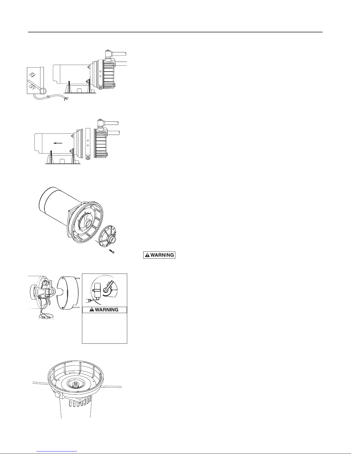
Figure 18 – Disconnect Power
Figure 19 – Slide Motor Back
NOTICE: Drain pump when disconnecting from service or when it might
freeze.
PUMP DISASSEMBLY
1. Disconnect power to motor.
NOTICE: Mark wires for correct assembly.
2. Remove clamp (see Figure 19).
3. Remove pump base mounting bolts. Motor assembly and back half of
pump can now be pulled away from pump front half (Figure 19).
CAREFULLY remove O-ring.
Figure 20 – Remove Diffuser
To avoid electrical
shock hazard, use
insulated-handle
screwdriver to short
capacitor terminals
as shown.
Figure 21 – Hold Shaft
CLEANING/REPLACING IMPELLER
NOTICE: First, follow instructions under “Pump Dis assembly”.
1. Remove four screws fastening diffuser to seal plate; remove diffuser (see
Figure 20). Exposed impeller can now be cleaned.
2. If impeller must be replaced, loosen two machine screws and remove
motor canopy (see Figure 21).
3.
Capacitor voltage may be hazardous. To discharge
capacitor, hold insulated handle screwdriver BY THE HANDLE and
short capacitor terminals together (see Figure 21). Do not touch metal
screwdriver blade or capacitor terminals. If in doubt, consult a qualified
electrician.
4. Unscrew capacitor clamp and remove capacitor. Do not disconnect
capacitor wires to motor.
5. Slide 7/16" open end wrench in behind spring loaded switch on
motor end of shaft; hold motor shaft with wrench on shaft flats and
unscrew impeller by turning counterclockwise when looking into eye of
impeller.
6. To reinstall, reverse steps 1 through 5.
7. See directions under “Pump Reassembly,” Page 12.
REMOVING OLD SEAL
1. Follow instructions under “Pump Disassembly”.
2. Follow steps 2 through 5 under “Cleaning/Replacing Impeller”.
3. Unscrew four nuts holding pump back half to motor. Remove rotating
half of seal by placing two screwdrivers under back half of pump body
and carefully prying up (Figure 22). Back half of pump body will slide
off shaft, bringing seal with it.
Figure 22 – Remove Seal plate
 Loading...