

Page 1

EN Instruction Manual
B 27977-3.1-1404
www.pts-jung.co.uk
PUMP TECHNICAL SERVICES LTD/JUNG PUMPEN
BAUFIX 5
0
1
Pump Technical Servcices Ltd/Jung Pumpen - Pump House - Unit 12 - Bilton Road
Industrial Estate - Erith - Kent - DA8 2AN - United Kingdom
Tel. +44 1322 357 080 - Fax +44 1322 341 341 - eMail: sales@pts-jung.co.uk
Page 2
2
Page 3

ENGLISH
You have purchased a product made by JUNG
PUMPEN and with it, therefore, also excellent quality and service. Secure this service
by carrying out the installation works in accordance with the instructions, so that our
product can perform its task to your complete
satisfaction. Please remember that damage
caused by incorrect installation or handling
will adversely affect the guarantee.
Therefore please adhere to the instructions in
this manual!
As with all electrical devices, this product
can also fail to operate due to an interruption
in the electricity supply or due to a technical defect. If this could result in damage, a
mains-independent alarm system must be
installed. Depending on the application, you
may also wish to install an emergency power
generator, or a second system as a back-up.
SAFETY
INSTRUCTIONS
This instruction manual contains essential
information that must be observed during
installation, operation and servicing. It is
therefore important that the installer and
the responsible technician/operator read this
instruction manual before the equipment is
installed and put into operation. The manual
must always be available at the location
where the pump or the plant is installed.
Failure to observe the safety instructions can
lead to the loss of all indemnity.
In this instruction manual, safety information
is distinctly labelled with particular symbols.
Disregarding this information can be dangerous.
General danger to people
Warning of electrical voltage
ATTENTION!
Danger to equipment and operation
Qualification and training of
personnel
All personnel involved with the operation,
servicing, inspection and installation of the
equipment must be suitably qualified for this
work and must have studied the instruction
manual in depth to ensure that they are sufficiently conversant with its contents. The supervision, competence and areas of responsibility of the personnel must be precisely
regulated by the operator. If the personnel do
not have the necessary skills, they must be
instructed and trained accordingly.
Safety-conscious working
The safety instructions in this instruction
manual, the existing national regulations
regarding accident prevention, and any internal working, operating and safety regulations
must be adhered to.
Safety instructions for the
operator/user
All legal regulations, local directives and
safety regulations must be adhered to.
The possibility of danger due to electrical energy must be prevented.
Leakages of dangerous (e.g. explosive, toxic,
hot) substances must be discharged such
that no danger to people or the environment
occurs. Legal regulations must be observed.
Safety instructions for installation, inspection and maintenance works
As a basic principle, works may only be carried out to the equipment when it is shut
down. Pumps or plant that convey harmful
substances must be decontaminated.
All safety and protection components must
be re-fitted and/or made operational immediately after the works have been completed.
Their effectiveness must be checked before
restarting, taking into account the current
regulations and stipulations.
Unauthorised modifications,
manufacture of spare parts
The equipment may only be modified or altered in agreement with the manufacturer.
The use of original spare parts and accessories approved by the manufacturer is important for safety reasons. The use of other
parts can result in liability for consequential
damage being rescinded.
Unauthorised operating
methods
The operational safety of the supplied equipment is only guaranteed if the equipment is
used for its intended purpose. The limiting
values given in the "Technical Data" section may not be exceeded under any circumstances.
Instructions regarding accident prevention
Before commencing servicing or maintenance
works, cordon off the working area and check
that the lifting gear is in perfect condition.
Never work alone. Always wear a hard hat,
safety glasses and safety shoes and, if necessary, a suitable safety belt.
Before carrying out welding works or using
electrical devices, check to ensure there is
no danger of explosion.
People working in wastewater systems must
be vaccinated against the pathogens that
may be found there. For the sake of your
health, be sure to pay meticulous attention to
cleanliness wherever you are working.
Make sure that there are no toxic gases in the
working area.
Observe the health and safety at work regulations and make sure that a first-aid kit is to
hand.
In some cases, the pump and the pumping
medium may be hot and could cause burns.
For installations in areas subject to explosion
hazards, special regulations apply!
This appliance can be used by children aged
8 years or over and by persons with limited
physical, sensory or intellectual capabilities,
or with limited experience and knowledge,
provided that they are supervised or have
been instructed in the safe use of the appliance and are aware of the dangers involved.
Children must not be allowed to play with the
appliance. Cleaning and user maintenance
must not be carried out by children unless
they are supervised.
3
Page 4

ENGLISH
USE
The sump is a conventional effluent collecting pit in conjunction with a separately orderd U3 KS or U3 KS special.
ATTENTION! Due to the space saving
tank design the U3 KS or the U3 KS can
only be operated with the low level float
which is part of the extent of delivery
ATTENTION! The connection between
the sump and the concrete can not be
sealed against pressing water. Do not
install the sump in areas with high
groundwater levels!
ATTENTION! In some countries it must
not be used for pumping sewage water
from lavatories.
The allowed temperature of the pumped
medium is 35 °C, short time period
60°C.
The screwed cover is smell-tight and
level compensating. The integrated and
smell-tight floor drain can be opend on
request.
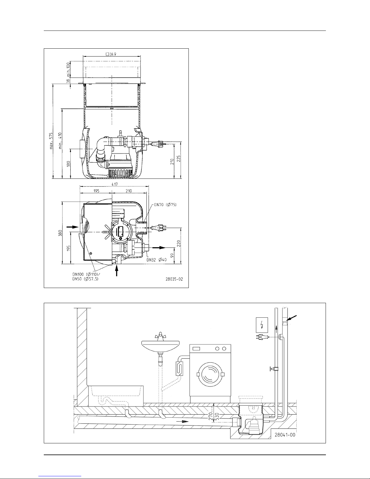
The PE-tank has two collateral inlet
sockets DN 100, offset by 90 °, one discharge socket for Ø 40 mm PVC pipe
and a vent socket DN70. The tank neck
with its adjustable and rotatable cover
allows an optimized level compensation
at the building site.
Extent of delivery
Underground sump Baufix 50 pre-assembled with male threaded pressure
outlet, non-return valve 1 ¼", nipple
40-1¼", cover frame with seal, lid with
sealing plug usable as a grommet, pipework, low level float, hose clamp with
snap buckle; profiled seal, hose clamp
1½" DN 40; siphon, elastic connection
and plug-in seals
ELECTRICAL
CONNECTION
Please refer to the relevant instructions
in the manual for the pump.
MOUNTING
The pressure tube must be taken in a
loop over the local backpressure level
and secured with a reflux valve. (EN
12056) The reflux valve is already installed in the BAUFIX 50.
Tank installation
1. Take the parts out of the tank. Do
not dismantle the pre-assembled
pipework or the reflux valve, because
they are already sealed.
2. Saw off the tank neck in the required
height along the marked grooves.
3. Push the profile packing with its
clamping groove on the edge of
the tank opening. The lips of the
seal must be directed to the inside.
Grease the seal and push the frame
a little bit declined into the opening.
Then adjust it und push the frame
into the opening completely, up to the
desired position (final floor height).
The air will escape audible out of the
seal. If the seal is rolled up, the installation must be repeated.
4. Open the required sockets for the inlet and the ventilation at the marked
positions with a saw or a knife and
remove the burr. Connect the inlet
and the ventilation pipes with PVCsleeves and O-rings (not included).
The pressure pipe must be glued
with a PVC sleeve onto the pressure
outlet.
5. After connection of all pipes, the
BAUFIX 50 must be levelled and
washed in. Do not remove the cover
during the installation to keep the
tank clean.
6. At concreting the base, the tank can be
secured against buoyancy by reinforcing steel at the welded wire mash.
.
7. Do not embed the frame in concrete.
It should stay adjustable to compensate floor pavements or tiles up to
100 mm.
8. Before carrying out the flooring
works adjust the frame in the planed
position and fasten it.
Pump installation
1. Seal the pump quarter elbow with
Teflon strap and screw it on the discharge branch.
2. Seal the thread of the pre-assembled
pipework with Teflon strap, screw it
in the quarter elbow of the pump and
adjust it as shown below.
3. Unscrew the standard float at the
control shaft, replace it by the low
level float and fasten it again with the
sheet metal screw.
4. Push the elastic connector up to the
end on the pipework and fasten it
with a hose clamp.
5. Push the hose clamp with the snap
buckle on the flexible connector. Insert the pump in the tank and push
the flexible connector on the reflux
valve. Fasten it with the hose clamp.
ATTENTION! Ensure the stable position of the pump as well as the free
movement of the float switch!
6. Pull the cable up to the T-piece
through the vent pipe. Enough cable has to be in the tank to allow the
pump to be pulled out of the tank for
servicing. The T-piece can then be
sealed with the slotted plug.
Installation of floor drain
1. Take out the 2 screws of the cover
plate and remove it.
2. Take the plug out of the cover connection piece with a screwdriver.
3. Screw the siphon with the union nut,
the packing and the expanding ring
on the connection piece.
4. The outlet of the siphon must not be
positioned directly above the pump.
5. At using the stainless steel frame,
grease the screws and screw down
the cover plate again.
4
Page 5

ENGLISH
Accessory alarm device
The alarm device signals an excessive
high water level. It can be installed subsequently. The cable is pulled through
the vent pipe and sealed in the same
way as the pump cable. The alarm unit
should be connected to a separate electric circuit, to ensure the operation in
case of a pump fault. Alternatively it can
be equiped with our 9V-rechargeable
battery for off the line operation.
Accessory special ventilation
If the ventilation over the roof level is not
possible, alternatively the special ventilation consisting of a ventilation screen
and 3 activated carbon filters can be installed with a T-piece in the cable pipe.
MAINTENANCE
The tank, the float switches and the foot
strainer of the pump should be inspected regularly and cleaned if necessary.
To service the pump, please refer to the
separate operating instruction.
ATTENTION! Always grease the screws
before using them to close the cover
plate and ensure the correct position of
the profiled seal.
5
Page 6

JUNG PUMPEN GmbH - Industriestr. 4-6 - 33803 Steinhagen - Deutschland
Tel. +49 5204 170 - Fax +49 5204 80368 - eMail kd@jung-pumpen.de
6
Pump Technical Services Ltd/Jung Pumpen - Pump House - Unit 12 - Bilton Road
Industrial Estate - Erith - Kent - DA8 2AN - United Kingdom
+44 1322 357 080 - Fax +44 1322 341 341 - eMail: sales@pts-jung.co.uk
 Loading...