

Pentair AUTOTROL LOGIX 740, AUTOTROL Performa 267, AUTOTROL Performa 265, AUTOTROL LOGIX 741, AUTOTROL LOGIX 742 Installer Manual
...
AUTOTROL
Performa 263-268
LOGIX 740-760
INSTALLER
MANUAL
WATER PURIFICATION

Installer Manual Performa 263-268 / LOGIX 740-760 - Table of content
Table of content
1. Generalities . . . . . . . . . . . . . . . . . . . . . . . . . . . . . . . . . . . . . . . . . . 5
1.1. Scope of the documentation . . . . . . . . . . . . . . . . . . . . . . . . . . . . . . . . 5
1.2. Release management . . . . . . . . . . . . . . . . . . . . . . . . . . . . . . . . . . . . . 5
1.3. Manufacturer identifier, product . . . . . . . . . . . . . . . . . . . . . . . . . . . .5
1.4. Abbreviations used . . . . . . . . . . . . . . . . . . . . . . . . . . . . . . . . . . . . . . . 6
1.5. Norms . . . . . . . . . . . . . . . . . . . . . . . . . . . . . . . . . . . . . . . . . . . . . . . . . . 6
1.5.1. Applicable norms . . . . . . . . . . . . . . . . . . . . . . . . . . . . . . . . . . . . . . . . . . . . 6
1.5.2. Available certificates . . . . . . . . . . . . . . . . . . . . . . . . . . . . . . . . . . . . . . . . . 7
1.6. Procedure for technical support . . . . . . . . . . . . . . . . . . . . . . . . . . . . 7
1.7. Copyright . . . . . . . . . . . . . . . . . . . . . . . . . . . . . . . . . . . . . . . . . . . . . . . 7
1.8. Limitation of liability . . . . . . . . . . . . . . . . . . . . . . . . . . . . . . . . . . . . . . 7
2. Safety . . . . . . . . . . . . . . . . . . . . . . . . . . . . . . . . . . . . . . . . . . . . . . . 8
2.1. Safety pictograms definition . . . . . . . . . . . . . . . . . . . . . . . . . . . . . . . . 8
2.2. Safety tags location . . . . . . . . . . . . . . . . . . . . . . . . . . . . . . . . . . . . . . 8
2.3. Hazards . . . . . . . . . . . . . . . . . . . . . . . . . . . . . . . . . . . . . . . . . . . . . . . . . 8
2.3.1. Personnel . . . . . . . . . . . . . . . . . . . . . . . . . . . . . . . . . . . . . . . . . . . . . . . . . . 9
2.3.2. Material . . . . . . . . . . . . . . . . . . . . . . . . . . . . . . . . . . . . . . . . . . . . . . . . . . . . 9
2.4. Hygiene and sanitization . . . . . . . . . . . . . . . . . . . . . . . . . . . . . . . . . . . 9
2.4.1. Sanitary issues . . . . . . . . . . . . . . . . . . . . . . . . . . . . . . . . . . . . . . . . . . . . . . 9
2.4.2. Hygiene measures . . . . . . . . . . . . . . . . . . . . . . . . . . . . . . . . . . . . . . . . . . . 9
3. Description . . . . . . . . . . . . . . . . . . . . . . . . . . . . . . . . . . . . . . . . . 10
3.1. Technical specifications . . . . . . . . . . . . . . . . . . . . . . . . . . . . . . . . . . 10
3.1.1. Performance flow rate characteristics. . . . . . . . . . . . . . . . . . . . . . . . . . 11
3.2. Outline drawing . . . . . . . . . . . . . . . . . . . . . . . . . . . . . . . . . . . . . . . . . 11
3.3. Description and components location . . . . . . . . . . . . . . . . . . . . . . . 12
3.4. Options available on the valve . . . . . . . . . . . . . . . . . . . . . . . . . . . . . 13
3.4.1. Chlorine generator (check salt light) . . . . . . . . . . . . . . . . . . . . . . . . . . . 13
3.4.2. Blending valve kit . . . . . . . . . . . . . . . . . . . . . . . . . . . . . . . . . . . . . . . . . . . 14
3.5. System regeneration cycle (8-cycles operation) . . . . . . . . . . . . . . . 15
3.6. Filter cycle (4-cycles operation) . . . . . . . . . . . . . . . . . . . . . . . . . . . . 17
4. System sizing . . . . . . . . . . . . . . . . . . . . . . . . . . . . . . . . . . . . . . . 19
4.1. Softener configuration (Performa 268) . . . . . . . . . . . . . . . . . . . . . . 19
4.1.1. Injector/DLFC/Refill flow controller-Valve configuration . . . . . . . . . . . 19
4.2. Filter configuration (Performa 263) . . . . . . . . . . . . . . . . . . . . . . . . . 19
4.3. Cycle time calculation . . . . . . . . . . . . . . . . . . . . . . . . . . . . . . . . . . . . 19
4.4. Injector flow rates (tables) . . . . . . . . . . . . . . . . . . . . . . . . . . . . . . . . 20
4.5. Salt amount definition . . . . . . . . . . . . . . . . . . . . . . . . . . . . . . . . . . . . 21
2 / 64 Ref. MKT-IM-011 / A - 15.06.2017

Installer Manual Performa 263-268 / LOGIX 740-760 - Table of content
5. Installation . . . . . . . . . . . . . . . . . . . . . . . . . . . . . . . . . . . . . . . . . .21
5.1. Safety notices for installation . . . . . . . . . . . . . . . . . . . . . . . . . . . . . 21
5.2. Installation environment . . . . . . . . . . . . . . . . . . . . . . . . . . . . . . . . . 21
5.2.1. General. . . . . . . . . . . . . . . . . . . . . . . . . . . . . . . . . . . . . . . . . . . . . . . . . . . 21
5.2.2. Electrical . . . . . . . . . . . . . . . . . . . . . . . . . . . . . . . . . . . . . . . . . . . . . . . . . 22
5.2.3. Mechanical. . . . . . . . . . . . . . . . . . . . . . . . . . . . . . . . . . . . . . . . . . . . . . . . 22
5.2.4. Outdoor Locations . . . . . . . . . . . . . . . . . . . . . . . . . . . . . . . . . . . . . . . . . . 23
5.3. Integration constraints . . . . . . . . . . . . . . . . . . . . . . . . . . . . . . . . . . 23
5.4. Block diagram and configuration example . . . . . . . . . . . . . . . . . . 24
5.5. Valve connection to piping . . . . . . . . . . . . . . . . . . . . . . . . . . . . . . . . 25
5.5.1. Top-mounted valve installation . . . . . . . . . . . . . . . . . . . . . . . . . . . . . . . 25
5.6. Connections (electrical) . . . . . . . . . . . . . . . . . . . . . . . . . . . . . . . . . . 26
5.7. Bypassing . . . . . . . . . . . . . . . . . . . . . . . . . . . . . . . . . . . . . . . . . . . . . 27
5.8. Drain line connection . . . . . . . . . . . . . . . . . . . . . . . . . . . . . . . . . . . . 28
5.9. Overflow line connection (Performa 268 - Softener
configuration only) . . . . . . . . . . . . . . . . . . . . . . . . . . . . . . . . . . . . . . 29
5.10. Brine line connection (Performa 268 - Softener
configuration only) . . . . . . . . . . . . . . . . . . . . . . . . . . . . . . . . . . . . . . 29
6. Programming . . . . . . . . . . . . . . . . . . . . . . . . . . . . . . . . . . . . . . . .30
6.1. Display . . . . . . . . . . . . . . . . . . . . . . . . . . . . . . . . . . . . . . . . . . . . . . . . 30
6.2. Commands . . . . . . . . . . . . . . . . . . . . . . . . . . . . . . . . . . . . . . . . . . . . 32
6.3. Basic programming . . . . . . . . . . . . . . . . . . . . . . . . . . . . . . . . . . . . . 33
6.3.1. Program system size . . . . . . . . . . . . . . . . . . . . . . . . . . . . . . . . . . . . . . . 33
6.3.2. Time setting and winter time - summer time change . . . . . . . . . . . . . 33
6.3.3. Day of week . . . . . . . . . . . . . . . . . . . . . . . . . . . . . . . . . . . . . . . . . . . . . . . 33
6.3.4. Regeneration time. . . . . . . . . . . . . . . . . . . . . . . . . . . . . . . . . . . . . . . . . . 34
6.3.5. Days to regenerate (740 time-clock controller only) . . . . . . . . . . . . . . 34
6.3.6. Calendar override (760 on-demand controller only) . . . . . . . . . . . . . . 34
6.3.7. Amount of brine used per regeneration . . . . . . . . . . . . . . . . . . . . . . . . 34
6.3.8. Estimated capacity . . . . . . . . . . . . . . . . . . . . . . . . . . . . . . . . . . . . . . . . . 35
6.3.9. Hardness (760 on-demand controller only) . . . . . . . . . . . . . . . . . . . . . 35
6.4. Advanced programming . . . . . . . . . . . . . . . . . . . . . . . . . . . . . . . . . . 36
6.4.1. Cycle time programming . . . . . . . . . . . . . . . . . . . . . . . . . . . . . . . . . . . . 36
6.4.2. Diagnostic . . . . . . . . . . . . . . . . . . . . . . . . . . . . . . . . . . . . . . . . . . . . . . . . 37
6.4.3. Resetting the controller . . . . . . . . . . . . . . . . . . . . . . . . . . . . . . . . . . . . . 37
7. Commissioning . . . . . . . . . . . . . . . . . . . . . . . . . . . . . . . . . . . . . . .38
7.1. Water filling, draining and waterproofness inspection . . . . . . . . . 38
7.1.1. Activating the softener . . . . . . . . . . . . . . . . . . . . . . . . . . . . . . . . . . . . . . 38
7.1.2. Additional tips . . . . . . . . . . . . . . . . . . . . . . . . . . . . . . . . . . . . . . . . . . . . . 40
7.2. Sanitization . . . . . . . . . . . . . . . . . . . . . . . . . . . . . . . . . . . . . . . . . . . . 40
7.2.1. Disinfection of water softeners . . . . . . . . . . . . . . . . . . . . . . . . . . . . . . . 40
Ref. MKT-IM-011 / A - 15.06.2017 3 / 64

Installer Manual Performa 263-268 / LOGIX 740-760 - Table of content
7.2.2. Sodium or calcium hypochlorite . . . . . . . . . . . . . . . . . . . . . . . . . . . . . . . 41
7.2.3. Electro chlorination . . . . . . . . . . . . . . . . . . . . . . . . . . . . . . . . . . . . . . . . . 41
8. Operation . . . . . . . . . . . . . . . . . . . . . . . . . . . . . . . . . . . . . . . . . . . 42
8.1. Recommendations . . . . . . . . . . . . . . . . . . . . . . . . . . . . . . . . . . . . . . . 42
8.2. Manual regeneration . . . . . . . . . . . . . . . . . . . . . . . . . . . . . . . . . . . . . 42
8.3. To advance regeneration cycles . . . . . . . . . . . . . . . . . . . . . . . . . . . .43
8.4. To cancel a regeneration . . . . . . . . . . . . . . . . . . . . . . . . . . . . . . . . . 43
9. Maintenance . . . . . . . . . . . . . . . . . . . . . . . . . . . . . . . . . . . . . . . . 44
9.1. Recommendations . . . . . . . . . . . . . . . . . . . . . . . . . . . . . . . . . . . . . . . 44
9.1.1. Use original spare parts. . . . . . . . . . . . . . . . . . . . . . . . . . . . . . . . . . . . . . 44
9.1.2. Use original approved lubricants . . . . . . . . . . . . . . . . . . . . . . . . . . . . . . 44
9.1.3. Maintenance instructions. . . . . . . . . . . . . . . . . . . . . . . . . . . . . . . . . . . . . 44
9.2. Cleaning and maintenance . . . . . . . . . . . . . . . . . . . . . . . . . . . . . . . . 44
9.2.1. Cleaning and maintenance. . . . . . . . . . . . . . . . . . . . . . . . . . . . . . . . . . . . 44
9.2.2. Cleaning the injector valve . . . . . . . . . . . . . . . . . . . . . . . . . . . . . . . . . . . . 45
9.2.3. Cleaning the refill controller . . . . . . . . . . . . . . . . . . . . . . . . . . . . . . . . . . 45
9.2.4. Cleaning the injector screen . . . . . . . . . . . . . . . . . . . . . . . . . . . . . . . . . . 46
9.2.5. Cleaning the backwash controller. . . . . . . . . . . . . . . . . . . . . . . . . . . . . . 46
9.2.6. Disassembling valve cover . . . . . . . . . . . . . . . . . . . . . . . . . . . . . . . . . . . 47
9.2.7. Motor and camshaft replacement . . . . . . . . . . . . . . . . . . . . . . . . . . . . . . 48
9.2.8. Optical sensor and controller replacement . . . . . . . . . . . . . . . . . . . . . . 49
9.2.9. Turbine cleaning or replacement . . . . . . . . . . . . . . . . . . . . . . . . . . . . . . 50
9.2.10. Top plate, flapper spring and flappers replacement. . . . . . . . . . . . . . . 51
10. Troubleshooting . . . . . . . . . . . . . . . . . . . . . . . . . . . . . . . . . . . . . 52
10.1. Logix controller . . . . . . . . . . . . . . . . . . . . . . . . . . . . . . . . . . . . . . . . . 52
10.2. Performa Valve . . . . . . . . . . . . . . . . . . . . . . . . . . . . . . . . . . . . . . . . . 53
11. Spare parts . . . . . . . . . . . . . . . . . . . . . . . . . . . . . . . . . . . . . . . . . 56
11.1. Valve parts list . . . . . . . . . . . . . . . . . . . . . . . . . . . . . . . . . . . . . . . . . . 56
11.2. 740 / 760 / 742 / 762 Controllers . . . . . . . . . . . . . . . . . . . . . . . . . . . 59
11.3. 1265 Bypass & Connections . . . . . . . . . . . . . . . . . . . . . . . . . . . . . . . 60
11.4. 268 Valve installation kits . . . . . . . . . . . . . . . . . . . . . . . . . . . . . . . . . 61
11.5. 263 Valve installation kits . . . . . . . . . . . . . . . . . . . . . . . . . . . . . . . . . 62
12. Scrapping . . . . . . . . . . . . . . . . . . . . . . . . . . . . . . . . . . . . . . . . . . . 63
4 / 64 Ref. MKT-IM-011 / A - 15.06.2017
Installer Manual Performa 263-268 / LOGIX 740-760 - Generalities
1. Generalities
1.1. Scope of the documentation
The documentation provides the necessary information for appropriate use of the product. It informs
the user to ensure efficient execution of the installation, operation or maintenance procedures.
The content of this document is based on the information available at the time of publication. The
original version of the document was written in English.
For safety and environmental protection reasons, the safety instructions given in this documentation
must be strictly followed.
This manual is a reference and will not include every system installation situation. The person
installing this equipment should have:
• Training in the 700 Logix series controllers and water softener installation;
• Knowledge of water conditioning and how to determine proper controller settings;
• Basic plumbing skills.
This document is available in other languages on https://www.pentairaquaeurope.com/productfinder/product-type/control-valves
1.2. Release management
Revision Date Author Description
A 15.06.2017 STF First edition
1.3. Manufacturer identifier, product
Manufacturer: Pentair Manufacturing Italy Srl
Via Masaccio, 13
56010 Lugnano di Vicopisano (PI) – Italy
Product: Performa 263-268 / LOGIX 740-760
Ref. MKT-IM-011 / A - 15.06.2017 5 / 64

Installer Manual Performa 263-268 / LOGIX 740-760 - Generalities
1.4. Abbreviations used
DF............................................................ Down Flow
UF............................................................ Up Flow
Inj ............................................................ Injector
DLFC ....................................................... Drain Line Flow Controller
BLFC / Refill Flow Controller................. Brine Line Flow Controller
Regen...................................................... Regeneration
SBV.......................................................... Safety Brine Valve
TC ............................................................ Time Clock
1.5. Norms
1.5.1. Applicable norms
Comply with the following guidelines:
• DM174: "Regulation of materials and objects that can be used in stationary collection, treatment,
supply and distribution of water intended for human consumption"
• Attestation de Conformité Sanitaire (ACS): "Test and Certification valid for France performed by
independent laboratories for the evaluation of materials and components that are in contact with
drinking water."
• 2006/42/EC: Machinery Directive
• 2014/35/UE: Low Voltage Directive;
• 2014/30/UE: Electromagnetic compatibility;
• 2011/65/EC: Restriction of use of certain hazardous substances in electrical and electronic
equipment (RoHS);
Meets the following technical standards:
• IEC/EN 60335-1
• IEC 61010-1
• EN 55014-1
• EN 55014-2
• EN 61000-3-2: 2006 + A1: 2009 + A2: 2009
• EN 61000-3-3: 2008
• EN 61000-6-2: 2005
• EN 61000-6-3: 2007 + A1: 2011
• EN 61326-1
6 / 64 Ref. MKT-IM-011 / A - 15.06.2017

Installer Manual Performa 263-268 / LOGIX 740-760 - Generalities
1.5.2. Available certificates
•CE •ACS
•DM174
Access to all certifications:
1.6. Procedure for technical support
Procedure to follow for any technical support request:
A Collect the required information for a technical assistance request.
→ Product identification (see 2.2. Safety tags location, page 8 and 9.1. Recommendations,
page 44);
→ Problem description of the device.
B Please refer to the "Troubleshooting" chapter, page 52. If the problem persists contact your
supplier.
1.7. Copyright
© 2017 Pentair International Sàrl All rights reserved.
1.8. Limitation of liability
Pentair Quality System EMEA products benefit, under specific conditions, from a manufacturer
warranty that may be invoked by Pentair’s direct customers. Users should contact the vendor of this
product for applicable conditions and in case of a potential warranty claim.
Any warranty provided by Pentair regarding the product will become invalid in case of:
• Improper installation, improper programming, improper use, improper operation and/or
maintenance leading to any kind of product damages;
• Improper or unauthorized intervention on the controller or components;
• Incorrect, improper or wrong connection/assembly of systems or products with this product and
vice versa;
• Use of a non-compatible lubricant, grease or chemicals of any type and not listed by the
manufacturer as compatible for the product;
• Failure due to wrong configuration and/or sizing.
Pentair accepts no liability for equipment installed by the user upstream or downstream of Pentair
products, as well as for process/production processes which are installed and connected around or
even related to the installation. Disturbances, failures, direct or indirect damages that are caused by
such equipment or processes are also excluded from the warranty. Pentair shall not accept any
liability for any loss or damage of profits, revenues, use, production, or contracts, or for any indirect,
special or consequential loss or damage whatsoever. Please refer to the Pentair List Price to know
more about terms and conditions applicable to this product.
Ref. MKT-IM-011 / A - 15.06.2017 7 / 64
Installer Manual Performa 263-268 / LOGIX 740-760 - Safety
A
A
A
Electrical
ratings
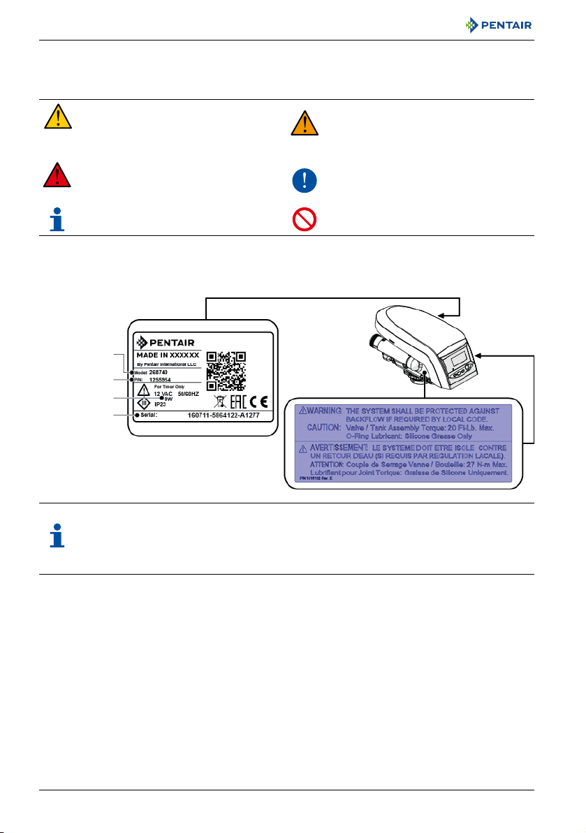
Serial number
Serial label
QR code (access
to installer
manual)
Installation warning
Part number
Model
A
2. Safety
2.1. Safety pictograms definition
Caution
Warns of a risk of minor injury or major
material damage to the device or
environment.
Danger
Warns against serious personal injury or
death.
Note
Comment
2.2. Safety tags location
A
Warning
Warns against serious personal injury
and damage to health.
A
Mandatory
Standard or measure to apply.
A
Prohibition
Restriction to be observed.
Note
Ensure that the safety tags on the device are completely legible and clean. If necessary,
replace them with new tags and put them in the same places.
2.3. Hazards
All the safety and protection instructions contained in this document must be observed in order to
avoid temporary or permanent injury, damage to property or environmental pollution.
At the same time, any other legal regulations, accident prevention and environmental protection
measures, as well as any recognized technical regulations relating to appropriate and risk-free
methods of working which apply in the country and place of use of the device must be adhered to.
Any non-observation of the safety and protection rules, as well as any existing legal and technical
regulations, will result in a risk of temporary or permanent injury, damage to property or
environmental pollution.
8 / 64 Ref. MKT-IM-011 / A - 15.06.2017

Installer Manual Performa 263-268 / LOGIX 740-760 - Safety
A
A
2.3.1. Personnel
Only qualified and professional personnel, based on their training, experience and instruction as well
as their knowledge of the regulations, the safety rules and operations performed, are authorized to
carry out necessary work.
2.3.2. Material
The following points must be observed to ensure proper operation of the system and the safety of
user:
• Be careful of high voltages present on the transformer (230V).
• Do not put your fingers in the system (risk of injuries with moving parts and shock due to electric
voltage).
2.4. Hygiene and sanitization
2.4.1. Sanitary issues
Preliminary checks and storage
• Check the integrity of the packaging. Check that there is no damage and no signs of contact with
liquid to make sure that no external contamination occurred.
• The packaging has a protective function and must be removed just before installation. For
transportation and storage appropriate measures should be adopted to prevent the
contamination of materials or objects themselves.
Assembly
• Assemble only with components which are in accordance with drinking water standards.
• After installation and before use, perform one or more manual regenerations in order to clean
the media bed. During such operations, do not use the water for human consumption. Perform a
disinfection of the system in the case of installations for treatment of drinking water for human
use.
Note
This operation must be repeated in the case of ordinary and extraordinary maintenance. It
should also be repeated whenever the system remains idle for a significant time.
Note
Valid only for Italy
: In case of equipment used in accordance with the DM25, apply all the
signs and obligations arising from the DM25.
2.4.2. Hygiene measures
Disinfection
• The materials used for the construction of our products meet the standards for use with potable
water; the manufacturing processes are also geared to preserving these criteria. However, the
process of production, distribution, assembly and installation, may create conditions of bacterial
proliferation, which may lead to odor problems and water contamination.
• It is therefore strongly recommended to sanitize the products. See 7.2. Sanitization, page 40.
• Maximum cleanliness is recommended during the assembly and installation.
• For disinfection, use Sodium or Calcium Hypochlorite and perform a manual regeneration.
Ref. MKT-IM-011 / A - 15.06.2017 9 / 64

Installer Manual Performa 263-268 / LOGIX 740-760 - Description
3. Description
3.1. Technical specifications
Design specifications/ratings
Valve body ............................................... Glass-filled Noryl
Rubber components ............................... Compounded for cold water - NSF listed material
Valve material certification .................... WQA Gold Seal Certified to ORD 0902, NSF/ANSI 44, CE, ACS
Weight (valve with controller) ................ 2.42 kg
Recommended operating pressure ....... 1.38 - 8.27 bar
Hydrostatic test pressure....................... 20.69 bar
Water temperature................................. 2 - 38°C
Ambient temperature............................. 2 - 48.9°C
®
- NSF listed material
Flow rates (valve only)
Service at 1.03 bar drop.......................... 5.7 m
Backwash at 1.72 bar drop..................... 4.5 m
Service .................................................... Kv = 5.6 m
Backwash................................................ Kv = 3.5 m
3
/h
3
/h
3
/h (Cv = 6.50 gpm)
3
/h (Cv = 4.00 gpm)
Valve connections
Tank thread............................................. 2½" - 8 NPSM, male
Inlet/Outlet threads ................................ 1¾" - 12 UNC - 2A male
Drain line ................................................ ¾" NPT, male
Brine line ................................................ ⅜" NPT, male
Distributor tube [Ø]................................. 27 mm (1.050")
Distributor tube [length]......................... 13 mm ± 3 mm (½ ± ⅛") above top of tank
Electrical
Controller Operating Voltage ................. 12 VAC (requires use of Pentair Water supplied transformer)
Input Supply Frequency.......................... 50 or 60 Hz (controller configuration dependent)
Motor Input Voltage ................................ 12 VAC
Controller Power Consumption ............. 3 W average
Protection rating..................................... IP23
10 / 64 Ref. MKT-IM-011 / A - 15.06.2017
Installer Manual Performa 263-268 / LOGIX 740-760 - Description
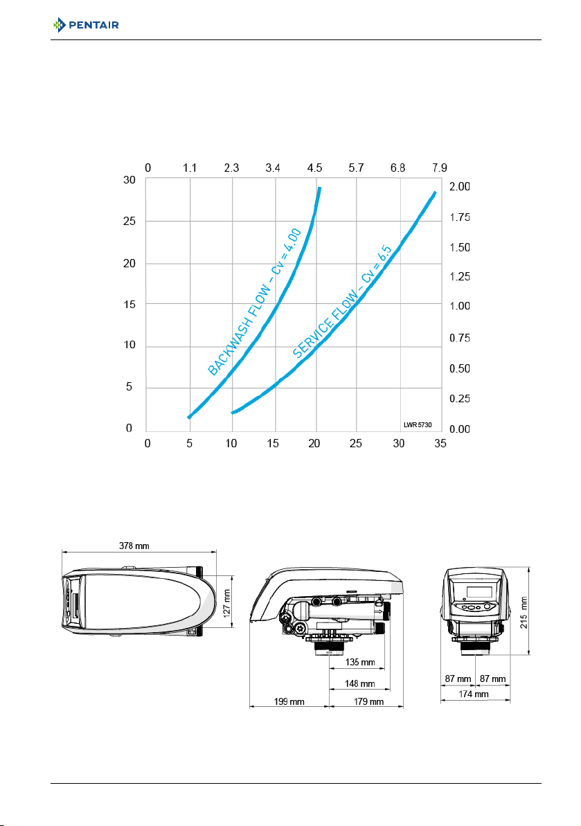
Flow rate (m3/h)
Flow rate in gallons per minute
Pressure drop (bar)
Pressure drop in psi
3.1.1. Performance flow rate characteristics
The graph shows the pressure drop created by the valve itself at different flow rates. It makes it
possible to predetermine the maximum flow rate going through the valve depending on the system
settings (inlet pressure etc). It also makes it possible to determine the valve pressure drop at a given
flow rate, and therefore to evaluate the system pressure drop vs flow rate.
3.2. Outline drawing
Ref. MKT-IM-011 / A - 15.06.2017 11 / 64
Installer Manual Performa 263-268 / LOGIX 740-760 - Description
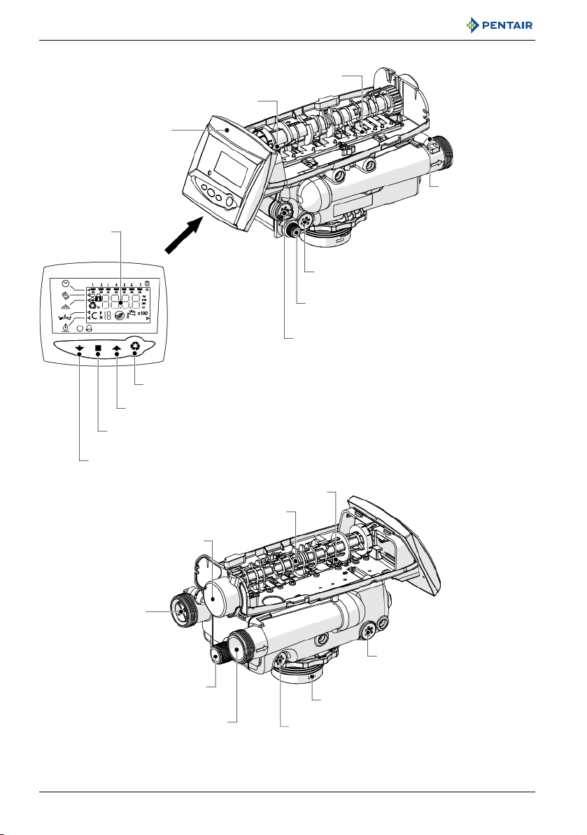
LCD display
DOWN button
SET button
UP button
Manual REGEN button
Control module mount
BLFC / Refill controller
Injector and cap
Brine tank tube connection
Tank thread
One-piece valve disc spring
Valve discs
Optical sensor
Camshaft
Motor
Drain
Inlet
Backwash flow drain controller
Injector screen
Outlet
Turbine cable
connection
3.3. Description and components location
12 / 64 Ref. MKT-IM-011 / A - 15.06.2017

Installer Manual Performa 263-268 / LOGIX 740-760 - Description
Chlorine generator
(check salt light)
A
3.4. Options available on the valve
3.4.1. Chlorine generator (check salt light)
The Logix 740 and 760 controllers have the capability to produce a low level of chlorine to chlorinate
the resin bed during regeneration. A check salt light will indicate when the user needs to add salt to
the brine tank. Potassium chloride or sodium chloride may be used.
No. Operation
A Unplug the wall-mounted transformer.
B Shut off water supply or put bypass valve(s) into bypass position.
C Relieve system pressure before performing any operations.
D Unlock the cover (2) from the slide clips (1) (one on each side of the valve).
E Remove the controller (3) by pressing on (4).
F Connect the small chlorine generator connector to the back of the controller (5).
Remove the existing refill controller (6) with the ball (7) from the valve and replace it with
G
the one provided in the kit.
Connect the other end of the cable to the refill controller previously installed.
H
Connect firmly to ensure a good contact.
I Reverse above procedure steps to rebuild.
Note
No programming is necessary for the chlorine generator to work properly on the controller.
The system will be automatically functional after the chlorine generation senses brine for
the first time. There is a check salt light on the front of the controller that will illuminate
when there is no brine present during the brine draw.
Ref. MKT-IM-011 / A - 15.06.2017 13 / 64
Installer Manual Performa 263-268 / LOGIX 740-760 - Description
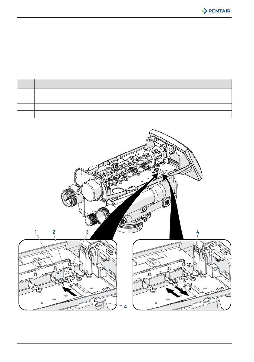
3.4.2. Blending valve kit
Tightening the adjusting screw provided by the kit will force the bypass flapper open. The open flapper
will allow untreated (hard) water to blend with the treated water supply. As the adjusting screw is
turned in, the hardness of the outlet water increases.
Loosening the adjusting screw will allow the bypass flapper to close. The closing action will blend less
untreated water into the outlet flow.
To blend a specific amount of hardness into outflow, adjust the screw and test the water. Repeat the
following procedure as needed until the desired harness level is reached.
No. Operation
A Insert the nut (3) into the blending valve orifice (2).
B Insert the adjusting screw (4) through the top plate and then through the nut.
C Tighten the adjusting screw (4) until it touches the bypass flapper (1).
D Adjust the position of the screw (4) until the desired hardness level of water is reached.
14 / 64 Ref. MKT-IM-011 / A - 15.06.2017

Installer Manual Performa 263-268 / LOGIX 740-760 - Description
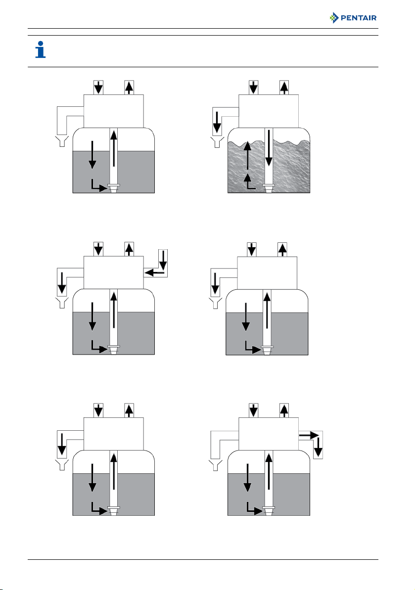
3.5. System regeneration cycle (8-cycles operation)
Service (downflow) — cycle C0
Untreated water is directed down through the resin bed and up through the riser tube. The hardness
ions attach themselves to the resin and are removed from the raw water being exchanged on the resin
beads against sodium ions. The water is conditioned as it passes through the resin bed.
Backwash (upflow) — cycle C1
The flow of water is reversed by the valve and directed down the riser tube and up through the resin
bed. During the backwash cycle, the bed is expanded and debris is flushed to the drain, while the
media bed is remixed.
Brine (downflow) — cycle C2
The controller directs water through the brine injector and brine is drawn from the brine tank. The
brine is then directed down through the resin bed and up through the riser tube to the drain. The
hardness ions are displaced by sodium ions and are sent to the drain. The resin is regenerated during
the brine cycle. When the air check valve closes brine drawing finishes, and then the slow rinse phase
starts.
Slow rinse (downflow) — cycle C3
Repressurize cycle (hard water bypass flapper open) — cycle C4
This cycle allows the air and water to hydraulically balance in the valve before continuing the
regeneration.
Fast rinse (downflow) — cycle C5
The controller value directs water down through the resin bed and up through the riser tube to the
drain. Any residual brine is rinsed from the resin bed, while the media bed is re-compacted.
2nd Backwash (upflow) — cycle C6
2nd Fast rinse (downflow) — cycle C7
Brine refill — cycle C8
Water is directed to the brine tank at a rate controlled by the refill controller, to create brine for the
next regeneration. During brine refill, treated water is already available at the valve outlet.
Ref. MKT-IM-011 / A - 15.06.2017 15 / 64
Installer Manual Performa 263-268 / LOGIX 740-760 - Description
A
From brine tank
BRINE/SLOW RINSE
C2 and C3
BACKWASH
C1 and C6
SERVICE
C0
FAST RINSE
C5 and C7
BRINE REFILL
C8
Valve
Valve
Valve
Valve Valve
Valve
REPRESSURIZE
C4
To brine tank
Note
For illustration purpose only. Always verify inlet and outlet marking on the valve.
16 / 64 Ref. MKT-IM-011 / A - 15.06.2017

Installer Manual Performa 263-268 / LOGIX 740-760 - Description
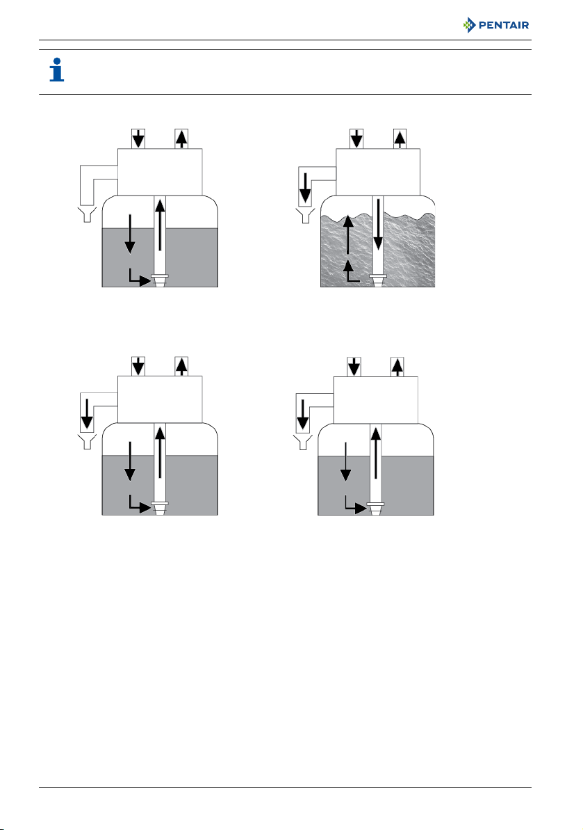
3.6. Filter cycle (4-cycles operation)
Service — cycle C0
Unfiltered water is directed down through the media and up through the riser tube. The water is
filtered as it passes through the media.
Backwash — cycle C1
The flow of water is reversed by the valve and directed down through the riser tube and up through
the media. During the backwash cycle, the media is expanded and debris is flushed to the drain.
Repressurize cycle (hard water bypass flapper open) — cycle C4
This cycle allows the air and water to hydraulically balance in the valve before continuing the
regeneration.
Fast rinse — cycle C5
The valve directs water down through the media and up through the riser tube to the drain while the
media is re-compacted.
Ref. MKT-IM-011 / A - 15.06.2017 17 / 64
Installer Manual Performa 263-268 / LOGIX 740-760 - Description
A
REPRESSURIZE
C4
BACKWASH
C1
SERVICE
C0
Valve Valve
Valve Valve
FAST RINSE
C5
Note
For illustration purpose only. Always verify inlet and outlet marking on the valve.
18 / 64 Ref. MKT-IM-011 / A - 15.06.2017
Installer Manual Performa 263-268 / LOGIX 740-760 - System sizing
4. System sizing
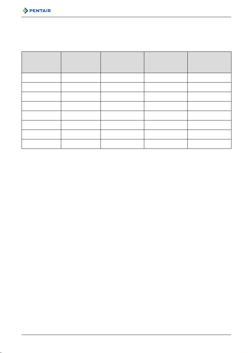
4.1. Softener configuration (Performa 268)
4.1.1. Injector/DLFC/Refill flow controller-Valve configuration
Vessel diameter
[In]
6 5 / 10 E [yellow] 0.33 0.9
7 15 F [peach] 0.33 1.2
8 20 G [tan] 0.33 1.6
9 30 H [lt purple] 0.33 2.0
10 35 J [lt blue] 0.33 2.5
12 40 K [pink] 0.33 3.5
13 50 L [orange] 0.33 4.1
14 80 L [orange] 0.33 4.8
Media volume
[L]
Injector Flow
control
Refill flow control
[gpm]
4.2. Filter configuration (Performa 263)
In filter configuration, the valve body, the camshaft and the controller are identical to the one used for
softening. The only difference is related to the valve configuration.
In filter mode, the injector size installed in the valve does not matter, it is only required to allow intern
pressure balancing during cleaning cycles. Refill flow controller is plugged.
The DLFC used is now related to the tank size and media type.
Backwash flow
control
[gpm]
4.3. Cycle time calculation
All the Logix controller range automatically calculates the unit capacity as well as the cycle time.
No calculations are therefore required.
Ref. MKT-IM-011 / A - 15.06.2017 19 / 64
Installer Manual Performa 263-268 / LOGIX 740-760 - System sizing
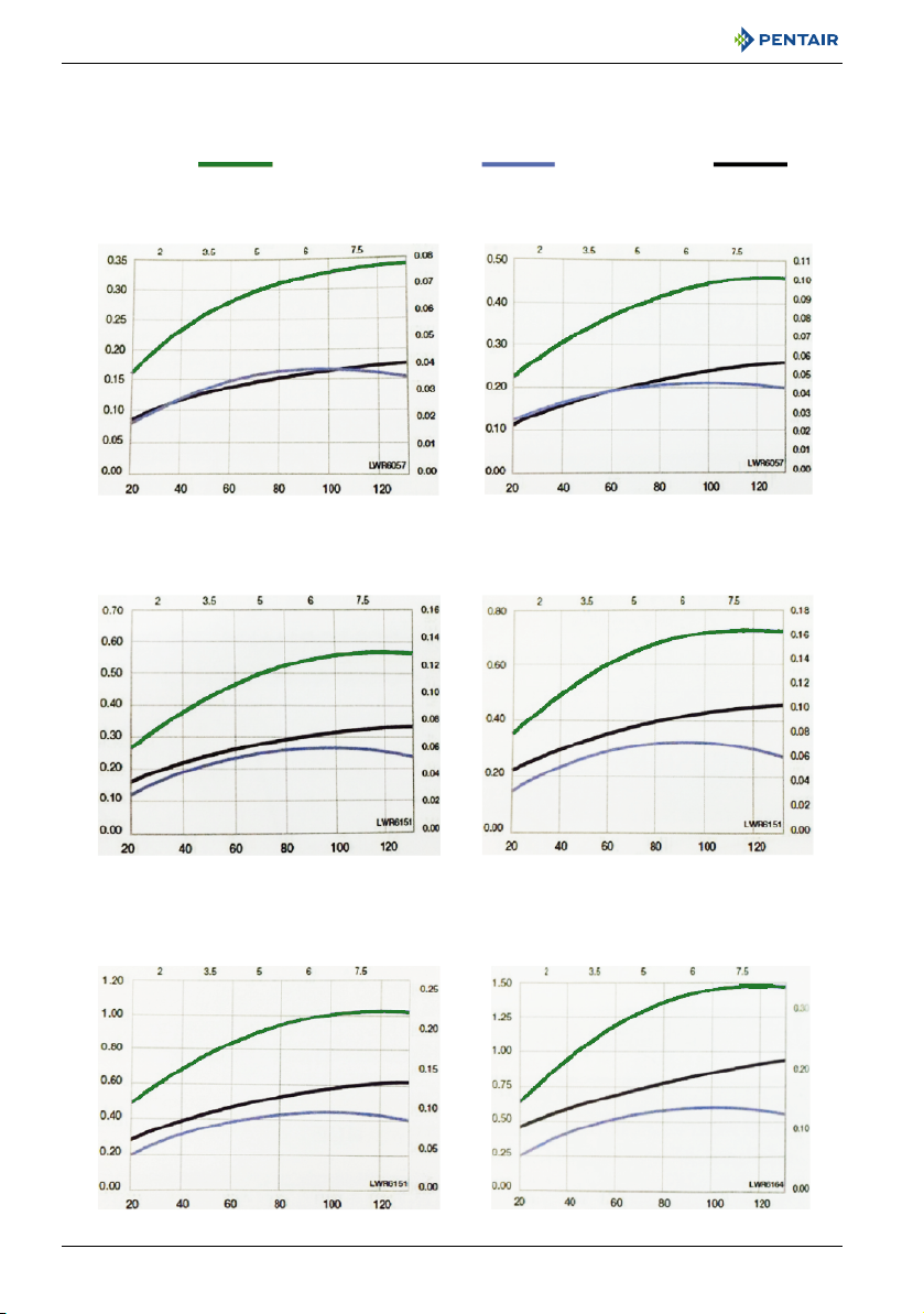
TOTAL BRINE DRAW
psi
Injector "F" (Peach)
For 7" Tanks
Injector "G" (Tan)
For 8" Tanks
Injector "H" (Light Purple)
For 9" Tanks
Injector "J" (Light Blue)
For 10" Tanks
Injector "K" (Pink)
For 12" Tanks
Injector "L" (Orange)
For 13 " and 14" Tanks
gpm
psi
psi psi
psi psi
bar bar
bar bar
barbar
gpmgpm
gpm gpm gpm
m
3
/h
m
3
/h
m
3
/h
m
3
/h
m
3
/h
m
3
/h
RINSE
4.4. Injector flow rates (tables)
The following tables represent the injectors flow rate as a function of the inlet pressure for the
different injector sizes.
20 / 64 Ref. MKT-IM-011 / A - 15.06.2017
 Loading...