

AUTOTROL® 255 VALVE/400 SERIES CONTROLS
SERVICE manual
www.pentairaqua.com

TABLE OF CONTENTS
WARNING:
MANUAL OVERVIEW ............................................................2
SAFETY INFORMATION ........................................................2
SYSTEM SPECIFICATIONS ................................................... 2
EQUIPMENT INSTALLATION ................................................ 4
SYSTEM STARTUP ................................................................6
PROGRAMMING ................................................................... 6
SERVICE AND MAINTENANCE ............................................ 9
255 VALVE & TANK ADAPTER MODULE ..........................10
255 SERIES ........................................................................12
TROUBLESHOOTING .........................................................14
FLOW DIAGRAMS ...............................................................16
FLOW DATA CHARTS .......................................................... 17
MANUAL OVERVIEW
How To Use This Manual
This installation manual is designed to guide the installer
through the process of installing and starting conditioners
featuring the 400 series controllers.
This manual is a reference and will not include every system
installation situation. The person installing this equipment
should have:
• Training in the 400 series controllers and water
conditioner installation
• Knowledge of water conditioning and how to determine
proper control settings
• Basic plumbing skills
• The directional instructions "left" and “right" are
determined by looking at the front of the unit.
SAFETY INFORMATION
Electrical
There are no user-serviceable parts in the AC adapter,
motor, or controller. In the event of a failure, these should be
replaced:
• All electrical connections must be completed according
to local codes.
• Use only the power AC adapter that is supplied.
• The power outlet must be grounded.
• To disconnect power, unplug the AC adapter from its
power source.
Mechanical
• Do not use petroleum based lubricants such as
petroleum jelly, oils, or hydrocarbon based lubricants.
Use only 100% silicone lubricants.
• All plastic connections should be hand tightened.
Plumber's tape may be used on connections that do not
use an O-ring seal. Do not use pliers or pipe wrenches.
• All plumbing must be completed according to local
codes.
• Soldering near the drain line should be done before
connecting the drain line to the valve. Excessive heat will
cause interior damage to the valve.
• Do not use lead-based solder for sweat solder
connections.
®
2 •AUTOTROL
255 Valve/400 Series Service Manual
• The drain line must be a minimum of 1/2" diameter. Use
3/4" pipe if the backwash flow rate is greater than 5 GPM
(18.9 Lpm) or the pipe length is greater than 20 feet (6
m).
• Do not support the weight of the system on the control
valve fittings, plumbing, or the bypass.
General
• Keep the media tank in the upright position. Do not turn
on side, upside down, or drop. Turning the tank upside
down will cause media to enter the valve.
• Operating ambient temperature is between 34ºF (1ºC)
and 120ºF (49ºC).
• Operating water temperature is between 34ºF (1ºF) and
100ºF (38ºC).
• Working water pressure range is 20 to 125 psi (1.38
to 8.61 bar). In Canada the acceptable working water
pressure range is 20 to 100 psi (1.38 to 6.89 bar).
• Use only regenerant salts designed for water softening.
Do not use ice melting, block, or rock salts.
• Follow state and local codes for water testing. Do not use
water that is micro-biologically unsafe or of unknown
quality.
• When filling media tank, do not open water valve
completely. Fill tank slowly to prevent media from exiting
the tank.
• When installing the water connection (bypass or
manifold) connect to the plumbing system first. Allow
heated parts to cool and cemented parts to set before
installing any plastic parts. Do not get primer or solvent
on O-rings, nuts, or the valve.
CALIFORNIA PROPOSITION 65 WARNING
This product contains chemicals known to the
State of California to cause cancer or birth
defects or other reproductive harm.
SYSTEM SPECIFICATIONS
D
C
N
E
A
R
T
D
I
F
E
T
S
E
T
U
N
D
E
R
I
N
D
U
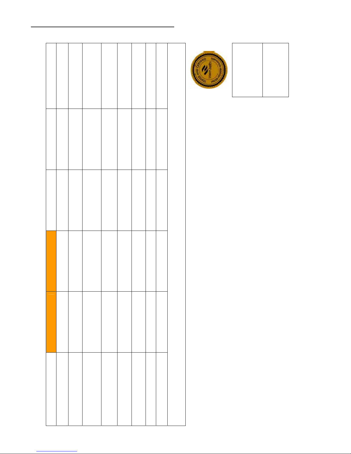
The 255 valve has been tested and certified by the WQA to
NSF/ANSI Std. 61 Section 8 Mechanical Devices
WQA Certified 255-460i Systems:
255-460i-075-844
255-460i-100-948
Working Pressure: 20-125 psi (1.38 - 8.61 bar)
Standard 12 Volt Transformer
Input Electrical Rating:
Optional 12 Volt Transformer
Input Electrical Rating:
Operating Ambient
Temperature:
Operating Water Temperature: 34-100°F (1-38°C)
For service or parts, please contact your local professional
water treatment dealer.
The systems below have been tested and certified
I
E
D
by the WQA to NSF/ANSI Std. 44 and NSF/ANSI 372
S
D
R
A
D
for “lead free” compliance.
N
A
T
S
S
T
Y
R
115V 60 Hz
115V 50 Hz, 230V 50 Hz,
230V 60 Hz, 100V 60 Hz,
100V 50 Hz
34-120°F (1-49°C)
SYSTEM SPECIFICATIONS continued
Tested and Certified by
WQA against NSF/ANSI
Standard 44 & NSF/ANSI
372 for “lead free”
compliance.
The valve used on this unit is
Tested and Certified by WQA
to NSF/ANSI Std. 61 Section
8 for Material Safety Only
28,263 @ 10.0
30,865 @ 14.0
PHONE: (262)-238-4400
PENTAIR Residential Filtration, LLC
20,483 @ 5.0
, Operating Temperature: 34 - 100° F or 1.1 – 38° C
2
5730 North Glen Park Road Milwaukee, Wisconsin 53209
WATER SOFTENER PERFORMANCE DATA SHEET
Model 255-460i-075-844 255-460i-100-948
Rated Service Flow (gpm) 6.0 10.0
9.0 15.0
15, 362 @ 3.75
Pressure Drop at Rated
Service Flow Rate (psi)
Rated Capacity
21,197 @ 7.5
23,148 @ 10.5
(grains @ lb. of salt)
Rated Efficiency
1.7 2.1
0.75 1.0
4,096/lb. salt @ 3.75 4,096/lb. salt @ 5.0
(grains/lb Salt @ lb. of salt)
Maximum Flow Rate During
Regeneration (gpm)
Sybron C-249NS
Ion Exchange Resin (cu. ft)
Backwash - GPM 1.7 2.1
Fast Rinse/Purge - GPM 1.7 2.1
Acceptable Salt Type: Sodium Chloride – Pellet or solar salt for water softeners
All Systems above tested at 35psi +/- 5 psi, pH of 7.5 +/- 0.5, Capacity Testing Flow Rate = 50% of the rated service flow rate for the various size systems.
Operating Pressure:20 -125 psi or 1.4 – 8.8 kg/Centimeter
dosage. Efficiency is measured by a laboratory test described in NSF/ANSI 44. The test represents the maximum possible efficiency the system can achieve. Operational efficiency is the actual
efficiency achieved after the system has been installed. It is typically less than the efficiency due to individual application factors including water hardness, water usage, and other contaminants that
salt efficiency of not less that 3350 grains of total hardness exchanged per pound of salt (based on NaCl equivalency) (477 grams of total hardness exchanged per kilogram of salt), and shall not
deliver more salt than its listed rating. The rated efficiency of the water softener, the salt dosage at that efficiency, the capacity at that salt dosage and that of the efficiency is only valid at the stated salt
reduce the water softener’s capacity. These systems are not intended to be used for treating water that is microbiologically unsafe or of unknown quality without adequate disinfection before or after
the system. Refer to the system Installation and Service Manuals for set-up and programming instructions.
Contact your local Autotrol dealer for parts and service. See your owner’s manual for warranty information.
Important Notice: For conditions of use, health claims certified by the California Department of Public Health and replacement parts, see product data sheet
Iowa Requirement:
AUTOTROL
Seller: ______________________________________________________________ Date: _________________________
Buyer: ______________________________________________________________ Date: _________________________
®
255 Valve/400 Series Service Manual • 3
Pentair Residential Filtration, LLC
These water softener systems have been tested by WQA and conform to NSF/ANSI 44 for specific performance claims as verified and substantiated by test data. The rated salt efficiencies above
were also determined in accordance with NSF/ANSI 44 and are only valid at the salt dosage referenced above. An efficiency rated water softener is a demand initiated regeneration (DIR) softener
which also complies with specific performance specifications intended to minimize the amount of regenerant brine and water used in its operation. Efficiency rated water softeners shall have a rated
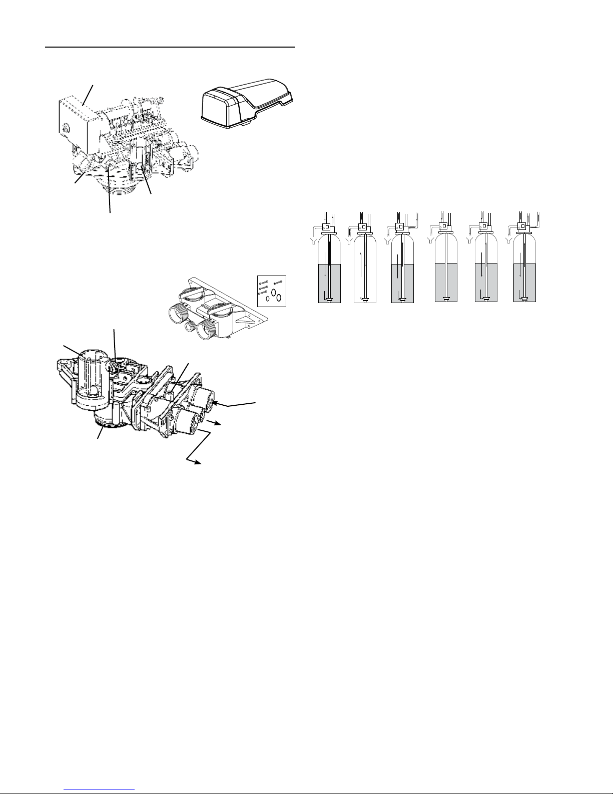
EQUIPMENT INSTALLATION
Autotrol 255 Valve Control Module Features
400 Series Control
Optional i-lid Cover
Variable Brine
Control
Injector Access Plug
Tank Adapter Module Features
Brine Line Fitting
Connection 1/4-inch NPT
Air Check
Tank Thread 2-1/2 inch - 8 male
System Regeneration Cycles
1. Service (Downflow):
Untreated water is directed down through the resin bed and up
through the riser tube. The hardness ions attach themselves
to the resin and are removed from the water. The water is
conditioned as it passes through the resin bed.
2. Backwash (Upflow):
The flow of water is reversed by the control valve and directed
down the riser tube and up through the resin bed. During the
backwash cycle, the bed is expanded and debris is flushed to
the drain.
3. Brine/Slow Rinse (Downflow):
The control directs water through the brine injector and brine
is drawn from the regenerant tank. The brine is then directed
down through the resin bed and up through the riser tube to
the drain. The hardness ions are displaced by sodium ions and
are sent to the drain. The resin is regenerated during the brine
cycle. Brine draw is completed when the air check closes.
Air Check
Figure 1
Optional Bypass
S
S
A
P
Y
B
Probe Connection Slot
Figure 2
S
S
A
P
Y
B
Inlet Connection
3/4-inch or 1-inch
NPT or BSPT
Drain Connection
3/8-inch or
1/2-inch NPT or
BSPT
Outlet connection
3/4-inch or 1-inch
NPT or BSPT
4. Fast Rinse (Downflow):
The control directs water down through the resin bed and
up through the riser tube to the drain. Any remaining brine
residual is rinsed from the resin bed.
5. Brine Refill (Downflow):
Brine refill occurs during a portion of the fast rinse cycle.
Water is directed to the regenerant tank at a controlled rate, to
create brine for the next regeneration.
6. Repressurize Cycle — (No Flapper Open):
This cycle closes all flappers for a short time to allow the
air and water to hydraulically balance in the valve before
continuing the regeneration.
BRINE REFILL
To Regenerant
Tank
From Regenerant
SERVICE BACKWASH BRINE/SLOW RINSE
C0 C1 and C6 C2 and C3
Tank
REPRESSURIZE
C4 C5 and C7 C8
FAST RINSE
Figure 3
NOTE: All plumbing must conform to local codes. Inspect
unit carefully for carrier shortage or shipping damage.
Location Selection
1. The distance between the unit and a drain should be as
short as possible.
2. If it is likely that supplementary water treating equipment
will be required, make certain adequate additional space
is available.
3. Since salt must be added periodically to the brine tank, the
location should be easily accessible.
4. Do not install any unit closer to a water heater than a total
run of 10 feet (3 m) of piping between the outlet of the
conditioner and the inlet to the heater. Water heaters can
sometimes overheat to the extent they will transmit heat
back down the cold pipe into the unit control valve. Hot
water can severely damage the conditioner. A 10 foot (3-m)
total pipe run, including bends, elbows, etc., is a reasonable
distance to help prevent this possibility. A positive way to
prevent hot water from flowing from heat source to the
conditioner, in the event of a negative pressure situation,
is to install a check valve in the soft water piping from
the conditioner. If a check valve is installed, make certain
the water heating unit is equipped with a properly rated
temperature and pressure safety relief valve. Also, be
certain that local codes are not violated.
5. Do not locate unit where it or it’s connections (including
the drain and overflow lines) will ever be subjected to room
temperatures under 34°F (1°C) or over 120°F (49°C).
6. Do not install unit near acid or acid fumes.
7. The use of resin cleaners in an unvented enclosure is
not recommended.
®
4 •AUTOTROL
255 Valve/400 Series Service Manual
EQUIPMENT INSTALLATION continued
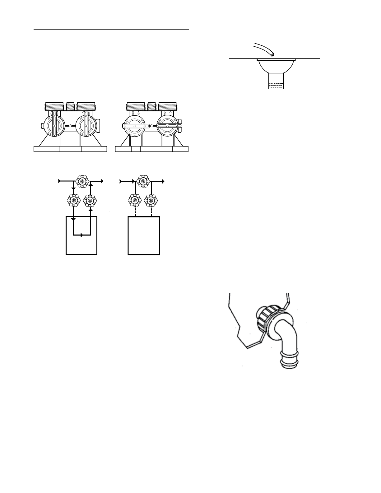
Water Line Connection
The installation of a bypass valve system is recommended to
provide for occasions when the water conditioner must be
bypassed for hard water or for servicing.
®
The most common bypass systems are the Autotrol
256 bypass valve (Figure 4) and plumbed-in globe valves
(Figure 5). Though both are similar in function, the 256
Autotrol bypass offers simplicity and ease of operation.
Not in Bypass
B
Y
P
A
S
S
B
Y
P
A
S
S
In Bypass
A
P
S
Y
S
B
Figure 4 Autotrol Series 256 Bypass Valve
Not in Bypass
Water
Conditioner
In Bypass
Water
Conditioner
Figure 5 Typical Globe Valve Bypass System
Drain Line Connection
1. Ideally located, the unit will be above and not more than
20 feet (6.1 m) from the drain. For such installations, use
an appropriate adapter fitting (not supplied), to connect
1/2 inch (1.3 cm) plastic tubing to the drain line connection
of the control valve.
2. If the unit is located more than 20 feet (6.1 m) from drain,
use 3/4 inch (1.9 cm) tubing for runs up to 40 feet (12.2 m).
Also, purchase appropriate fitting to connect the 3/4 inch
tubing to the 1/2 inch NPT drain connection.
3. If the unit is located where the drain line must be elevated,
you may elevate the line up to 6 feet (1.8 m) providing the
run does not exceed 15 feet (4.6 m) and water pressure
at conditioner is not less than 40 psi (2.76 bar). You may
elevate an additional 2 feet (61 cm) for each additional
10 psi (0.69 bar).
4. Where the drain line is elevated but empties into a drain
below the level of the control valve, form a 7-inch (18 cm)
loop at the far end of the line so that the bottom of the loop
is level with the drain line connection. This will provide an
adequate siphon trap.
5. Where the drain empties into an overhead sewer line, a
sink-type trap must be used.
IMPORTANT: Never insert drain line into a drain, sewer line or
trap. Always allow an air gap between the drain line and the
wastewater to prevent the possibility of sewage being backsiphoned into conditioner.
Series
A
P
S
Y
S
B
Correct Way
Drain Line Tube
Right Way
Drain
Figure 6
NOTE: Standard commercial practices have been expressed
here. Local codes may require changes to
these suggestions.
Brine Line Connection
It will be necessary to install the brine tube and line to a fitting
installed on the air check. Apply plumber tape on all
threaded connections.
Be sure all fittings and connections are tight so that premature
checking does not take place. Premature checking is when
the ball in the air check falls to the bottom before all brine
is drawn out of the brine tank. See Placing Conditioner into
Operation section.
Overflow Line Connection
In the absence of a safety overflow and in the event of
a malfunction, the BRINE TANK OVERFLOW will direct
“overflow” to the drain instead of spilling on the floor where it
could cause considerable damage. This fitting should be on the
side of the cabinet or brine tank.
To connect overflow, locate hole on side of brine tank. Insert
overflow fitting (not supplied) into tank and tighten with plastic
thumb nut and gasket as shown (Figure 7). Attach length of
1/2 inch (1.3 cm) I.D. tubing (not supplied) to fitting and run to
drain. Do not elevate overflow line higher than 3 inches
(7.6 cm) below bottom of overflow fitting. Do not tie into drain
line of control unit. Overflow line must be a direct, separate
line from overflow fitting to drain, sewer or tub. Allow an air
gap as per drain line instructions (Figure 6).
Brine Tank
Overflow Fitting
Installed
Connect 1/2-inch
(1.3 cm) Tubing or
Hose and Run to
Drain
Figure 7
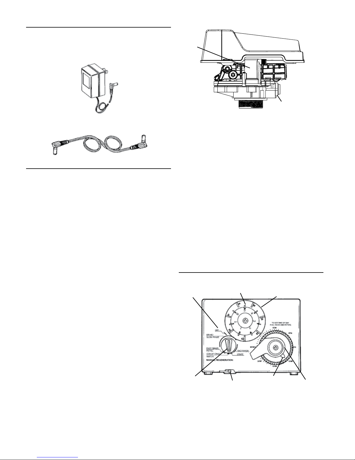
Low Voltage Transformer
Use only the included transformer for powering the 400 series
timers. Connect the plug of the transformer secondary cable
to the mating socket on the control (see Figure 8).
Be certain that the transformer is plugged into a correct
voltage source that is not controlled by a wall switch.
AUTOTROL
®
255 Valve/400 Series Service Manual • 5
EQUIPMENT INSTALLATION continued
Increasing the Length of the Transformer Cord
If it is necessary to extend the length of the transformer cord,
an optional 15 foot (4.6 m) extension is available
(see Figure 9).
Figure 8
SYSTEM STARTUP
Initial Startup
After the water conditioning system is installed, the
conditioner should be disinfected before it is used to treat
potable water. Refer to the Disinfection of Water Conditioners
section in this manual. Complete the following steps to place
the conditioner into operation:
1. Remove control valve cover.
NOTE: The following steps will require turning the indicator
knob (Figure 11) to various positions. Insert a
wide-blade screwdriver into arrow slot in indicator
knob and press in firmly. With knob held in, rotate
COUNTERCLOCKWISE only until arrow or knob points
to desired position. Rotation is made much easier if
you grasp the camshaft with your free hand and turn it
at the same time. Then permit knob to spring back out.
2. Insert screwdriver into slot in indicator knob (Figure 11).
Press in and rotate knob COUNTERCLOCKWISE until arrow
points directly to the word BACKWASH.
3. Fill resin tank with water.
a. With water supply off, place the bypass valve(s) into the
“NOT IN BYPASS” position.
b. Open water supply valve very slowly to approximately
the 1/4 open position.
IMPORTANT: If opened too rapidly or too far, resin may be lost.
In this position, you should hear air escaping slowly from the
drain line.
c. When all of the air has been purged from the tank
(water begins to flow steadily from the drain), open the
water supply valve all the way.
d. Allow water to run to drain until clear.
e. Turn off water supply and let the unit stand for about
five minutes. This will allow all trapped air to escape
from the tank.
4. Add water to brine tank (initial fill). With a bucket or hose,
add approximately 4 gallons (15 liters) of water to brine
tank. If the tank has a salt platform above the bottom of the
tank, add water until the level is approximately 1 inch
(25 mm) above the platform.
Air Check
Brine Line
Figure 9 - Control Valve
5. Put into operation.
a. Open water supply valve slowly to full open position.
b. Carefully advance indicator knob
COUNTERCLOCKWISE to center of FAST RINSE/REFILL
position and hold there until air check (Figure 10) fills
with water and water starts to flow through brine line
into brine tank. Do not run for more than two minutes.
c. Advance indicator knob COUNTERCLOCKWISE until
arrow points to the center of the BRINE/SLOW
RINSE position.
d. With the conditioner in this position, check to see if
water is being drawn from the brine tank. The water
level in the brine tank will recede very slowly. Observe
for at least three minutes. If the water level does not
recede or goes up, or if air enters the transparent air
check chamber and the ball falls and seats, reference
Troubleshooting section.
e. Advance indicator knob COUNTERCLOCKWISE to
CONDITIONED WATER.
f. Run water from a nearby faucet until the water is clear
and soft.
PROGRAMMING
440i Control (obsolete)
Day Arrow
Indicator Knob
Skipper Pins
Timer
Locking Pin
Figure 10
Skipper Wheel
Time Arrow
Timer Knob
6 •AUTOTROL
®
255 Valve/400 Series Service Manual
 Loading...