

Pentair AURORA 342A, AURORA 344A, AURORA 341A Instruction And Repair Manual
MODELS 341A, 342A and 344A
MODEL 342A
MODEL 341A
MODEL 344A
SINGLE STAGE END SUCTION PUMPS
INSTRUCTION AND REPAIR MANUAL
NOTE! To the installer: Please make sure you provide this manual to the owner of the equip ment or to the responsible
party who maintains the system.
Part # A-03-279 | © 2012 Pentair Ltd. | 12/03/12
NOTE
This repair manual is applicable to pump Models 341A,
342A and 344A. All photos illustrate Model 344A.
ATTENTION: SAFETY WARNINGS:
Read and understand all warnings before installation or servicing pump.
CALIFORNIA PROPOSITION 65 WARNING:
SECTION 6 ITEM 340
DATED JUNE 1998
SUPERSEDES ITEMS 341, 342, 344
DATED MARCH 1992
Warning: Spraying Water Hazard
When servicing pump replace all gaskets and seals. Do not
re-use old gaskets or seals. Failure to follow these instructions could result in serious personal injury, death or property damage.
HIGH PRESSURE SAFETY:
Warning: This product and related accessories
contain chemicals known to the State of California to
cause cancer, birth defects or other reproductive harm.
OPERATIONAL LIMITS: *
Maximum Operating Pressure: 175 psi at Temperatures
to 150OF (65.6°C)
Maximum Operating Temperature: 225°F (107°C)
* See ASTM A126/ANSI B16.1 for pressure/temperature rat-
ings of flanges.
ELECTRICAL SAFETY:
Warning: Electrical Shock Hazard
All electrical connections are to be made by a qualified electrician in accordance with all codes and ordinances. Failure
to follow these instructions could result in serious personal
injury, death or property damage.
Warning: Electrical Overload Hazard
Insure all motors have properly sized overload protection.
Failure to follow these instructions could result in serious
personal injury, death or property damage.
Warning: High Pressure Hazard
The pump is rated at a maximum of 175 psi at 150°F. Do
not exceed this pressure. Install properly sized pressure
relief valves in system. Failure to follow these instructions
could result in serious personal injury, death or property
damage.
Warning: Expansion Hazard
Water expands when heated. Install properly sized thermal
expansion tanks and relief valves. Failure to follow these
instructions could result in serious personal injury, death or
property damage.
SERVICE
Your Aurora pump requires no maintenance other than periodic inspection, occasional cleaning and lubrication of bearings
(MODEL 344A only). The intent of inspection is to prevent
breakdown, thus obtaining optimum service life. The liquid end
of the pump is lubricated by the fluid being pumped and therefore does not require periodic lubrication. The motor, however
may require lubrication, in which case, the motor manufacturer’s recommendation should be followed.
LUBRICATION OF IMPELLER SHAFT BEARINGS
Warning: Sudden Start-Up Hazard
Disconnect and lockout power source before servicing.
Failure to follow these instructions could result in serious
personal injury, death or property damage.
HIGH TEMPERATURE SAFETY:
Warning: Hot Surface Hazard
If pumping hot water, insure guards or proper insulation is
installed to protect against skin contact to hot piping or pump
components. Failure to follow these instructions could result
in serious personal injury, death or property damage.
2
The MODEL 344A pump is available with three options for
lubricating the shaft bearings. They are:
1. Regreasable (standard)
2. Oil Lubrication
3. Sealed Bearings, Permanent Lubrication
Regreasable bearings will require periodic lubrication and can
be accomplished by using the zerk or lubrication fittings in
the cartridge cap and power frame. Lubricate the bearings at
regular intervals using a grease of high quality. Polyurea base
grease is recommended as lubricants for pumps oper at ing in
both wet and dry locations. Mixing of different brands of grease
should be avoided due to possible chemical reactions between
the brands which could damage the bearings. Accordingly,
avoid grease of vegetable or animal base which can develop
acids, as well as grease containing rosin, graphite, talc and
other impurities. Under no circumstances should used grease be
reused.
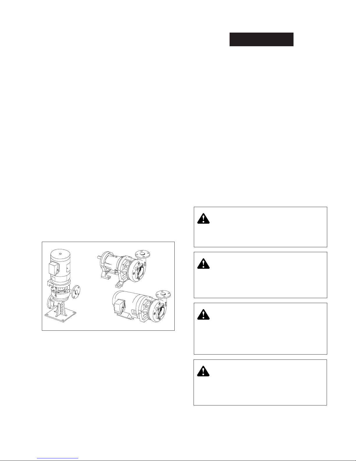
MODELS 341A-342A-344A
Model 342A
Model 341A
Model 344A
Over lubrication should be avoided as it may result in overheating and possible bearing failure. Under normal application, adequate lubrication is assured if the amount of grease is
maintained at 1/3 to 1/2 the capacity of the bearing and adjacent
space surrounding it.
CAUTION
Use normal fire caution procedures when using any
petroleum cleaner.
In dry locations, each bearing will need lubrication at least
every 600 hours of running time or every 6 to 12 months,
whichever is more frequent. In wet locations the bearings
should be lubricated at least after every 300 hours of running
time or every 4 to 6 months, whichever is more frequent. A unit
is considered to be installed in a wet location if the pump and
motor are exposed to dripping water, to the weather, or to heavy
condensation such as is found in unheated and poorly ventilated
underground locations.
Oil lubricated bearings are optional on MODEL 344 pumps. A
fixed oil level is maintained with the power frame by an oiler
which allows visual indications of reserve oil.
At initial installation and before starting a unit that has been
shut down for repairs or for any extended length of time, run
enough 10W-30 weight motor oil through the oiler to maintain a constant oil level to insure that the bearing will never be
without an oil supply. Oil will have to be added at intervals to
maintain a constant level in the oiler. This interval can only be
determined by experience.
Under working conditions, oil will breakdown and need to be
replaced at regular intervals. The length of these intervals will
depend on many factors. Under normal operation, in clean and
dry locations, the oil should be changed about once a year.
However, when the pump is exposed to dirt contamination, high
temperatures (200°F. or above) or a wet location, the oil may
have to be changed every 2 to 3 months.
REPAIRS
Before starting any work, insure the electrical power is locked
out, the system pressure has been lowered to 0 psi and temperature of the unit is at a safe level.
The pump may be disassembled using the illustrations and text
provided. Although complete disassembly is covered, it will
seldom be necessary to completely disassemble your Aurora
pump.
The illustrations accompanying the disassembly instructions
show the pump at various stages of disassembly. The illustrations are intended to aid in the correct identification of the parts
mentioned in the text.
Inspect removed parts at disassembly to determine if they can
be reused. Ball bearings that turn roughly or show wear should
be replaced. Cracked castings should never be reused. Scored
or worn pump shafts should be replaced. Gaskets should be
replaced at reassembly simply as a matter of economy. They are
much less expensive to replace routinely than to replace singly
as the need arises.
Warning: Sudden Start-Up Hazard
Disconnect and lockout power source before servicing.
Failure to follow these instructions could result in serious
personal injury, death or property damage.
A. Assembled Units.
Warning: Hot Surface Hazard
If pumping hot water, insure guards or proper insulation
is installed to protect against skin contact to hot piping or
pump components. Failure to follow these instructions could
result in serious personal injury, death or property damage.
Warning: High Pressure Hazard
The pump is rated at a maximum of 175 psi at 150°F. Do
not exceed this pressure. Install properly sized pressure
relief valves in system. Failure to follow these instructions
could result in serious personal injury, death or property
damage.
Warning: Spraying Water Hazard
When servicing pump replace all gaskets and seals. Do not
re-use old gaskets or seals. Failure to follow these instructions could result in serious personal injury, death or property damage.
3
MODELS 341A-342A-344A
DISASSEMBLY
Disassemble only what is needed to make repairs or accomplish
inspection. (See Figure 2 for Model 341A, Figure 3 for Model
342A and Figure 3 for Model 344A.)
1. Disconnect and lockout power source to prevent drive unit
from being energized during disassembly.
2. Unscrew the two drain plugs (4) from the casing (6). On
Model 342A pumps, remove plugs (74 and 75) to drain
pump. Also unscrew the two plugs (4) from casing (6).
3. Remove all relief, cooling, flushing or drain lines from
pump, including compression connections (1 and 2) and
tubing (3). Break suction and discharge connections unless
it is intended to remove the power frame or motor assembly
and leave casing (6) in the line. On Model 342A pumps,
break discharge connections only, unless it is desired to
remove base (73). Remove capscrews (39) and lift pump
assembly from base (73). Remove gasket (72).
4. On Model 344A pumps, remove the flexible coupling from
between the pump and motor. Next unscrew the bolts that
hold support(s) (41 and 64) to the base and slide the pump
out to be worked on.
5. Remove capscrews (5) and pull casing (6) from bracket
(35). Remove gasket (8).
C. Impeller and Key Removed.
9. Impeller wearing rings (optional - 14 and 15) are pressed on
and must be cut off if replacement is necessary. If they are
turned off in a lathe, take care not to cut into the impeller.
10. Slide sleeve (25) with rotating parts of mechanical seal (27)
from the shaft. The sleeve should be carefully cleaned to
remove any residue that may be remaining in the seal area.
The rubber in seal (27) may have become partially adhered
to the sleeve. The sleeve must also be checked for abrasion
or corrosion that can occur when fluid residue penetrates
between the seal (27) and sleeve (25). The sleeve under
the seal may be polished lightly to a 32 RMS finish before
reassembly. Do not reuse a pitted sleeve. Pin (61) may be
removed if necessary.
6. Unscrew impeller screw (9) and remove washer (9A), taking care not to damage gasket (9B) or capscrew seal (9C).
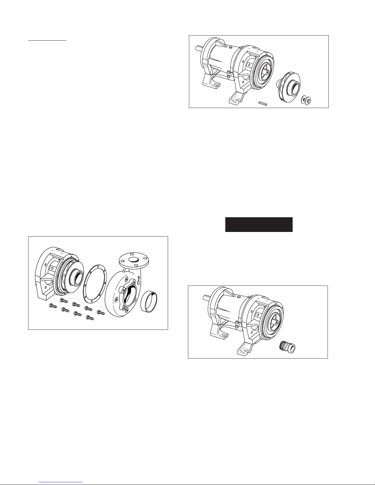
B. Casing, Gasket, and Wearing Ring Removed.
7. Slide impeller (11) and impeller key (12) from the shaft,
again taking care not to damage gasket (10) located behind
impeller. Remove gasket (10).
8. Wearing ring(s) (7 and 16) are pressed into their housings
with an interface fit and must be removed with a puller.
New ring(s) should be used for reassembly since it is likely
that during removal this fit will be lost. Do not remove
wearing rings if not being replaced.
CAUTION
The mechanical seal (see Figure 1) is a precision product
and must be treated as such. During removal, great care
must be taken to avoid dropping any part of the seal.
Take particular care not to scratch the lapped faces on the
washer or the sealing seat. If any wear of the seal faces is
noted, it is recommended to replace with a new seal during reassembly.
D. Mechanical Seal Removed.
11. On Model 344A pumps, remove capscrews (39 and 62) and
washers (40 and 63) to take off support feet (41 and 64).
On Model 341A frame size 143 thru 184-JM only, unscrew
capscrews (39) washers (40) and remove support (41) from
bracket (35).
4
12. Unscrew capscrews (32) to remove bracket (35) from frame
(57) or motor on Models 341A and 342A.
 Loading...