

Page 1
Instruction Manual
Electronic Control Pump
ISO 9001 Certified
AQ Series
Page 2

~ 1 ~
EC Declaration of Conformity
Pentair Southern Cross declares that the machinery described:
Name : Water Pump
Model : AQ Series
Conform to the following directive:
2006/42/EC—Machinery directive
2006/95/EC—Low voltage directive
2004/108/EC—EMC (Electromagnetic compatibility) directive
Refer to the following standards:
EN ISO 12100-1:2003 EN ISO 12100-2:2003
ISO14121-1:2007
EN60335-1:2001 EN 809:1998
EN60335-2-41:2001
EN61000-6-2 EN61000-6-3
Page 3
Please read all instructions carefully before
installing your new systems, as failures caused by
incorrect installation or operation are not covered
by the warranty.
1. Introduction
1.1 Applications:
The AQ series pumps are designed for water supply
and pressure boosting in residential, commercial
and light industrial applications where low or
inadequate water pressure exists. It is suitable for
boosting pressure from underground or surface
water supplies.
1.2 Product Features:
1.2.1 Consisting of pump, motor, and electronic
controller. The built-in electronic controller
provides constant pressure which ensures
that the pump starts automatically when
water is consumed and operates continuously
until water is not required.
1.2.2 Compact design and quiet operation make the
AQ suitable for many applications.
1.2.3 The AQ is constructed from the top quality
corrosion resistant materials.
1.2.4 The motor has built-in thermal overload to
protect against high operating temperatures
and over current.
1.2.5 No pressure tank design
Easy to install and saving space.
1.2.6 Dry-run protection:
automatic reset function.
1.3 Controller instruction
When the pump starts to deliver water, the pressure
switch will sense system pressure and compare it
with the preset pressure. It will automatically start
the pump if system pressure is lower than the
preset pressure.
1.4 Operation Conditions:
1. Ambient temperature: Max. +40°C
2. Liquid temperature: +4°C ~ +40°C
3. System Pressure : Max. 8.5 kg/cm²
4. Relative humidity: Max. 85% (RH)
5. Under normal operation, it is not necessary to
adjust the pressure unless the cut in pressure is
higher than preset activation point (refer to
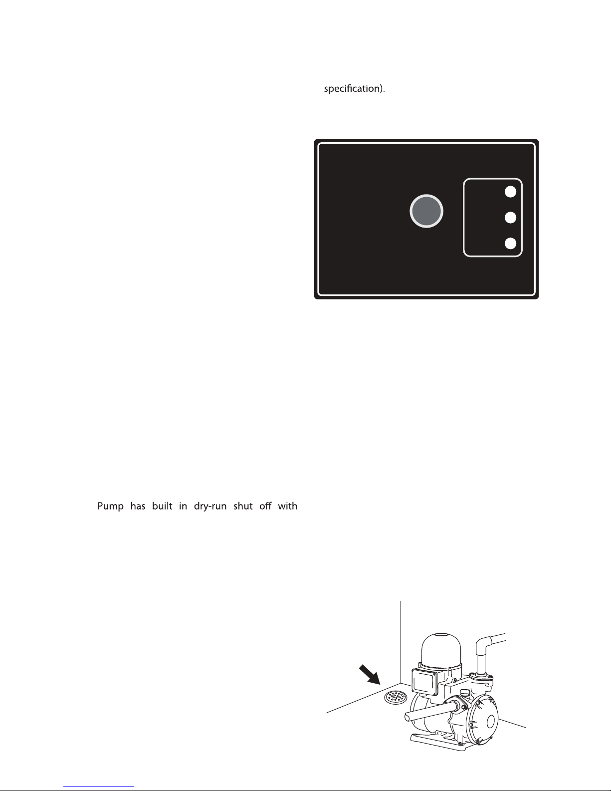
2. Automatic Pump Control
2.1 Power
Status indicator Tension LED
2.2 Failure
Faulty alarm LED
2.3 On
Light include: Pump-working LED
2.4 Reset
Manual reset switch
3. Installation
1. Choose a site with sold foundation, dry and good
ventilation. Please provide accessible space
around the pump and leave at least 30cm
clearance between your motor end to the wall.
2. Indoor: TO avoid water, do not install the pump
on ceiling, carpet or any place close to electrical
appliances. Make sure to provide a drain hole to
waste.
~ 2 ~
R
e
s
e
t
Power
Failure
On
AQ200
AQ200
ELECTRONIC CONTROL PUMP
Drain hole
When all taps are turned o there will be no ow
through the Reed switch and teh pump will
automatically shut o.
Page 4

3. Outdoor: When the pump is installed outside,
please provide a suitable cover to protect it from
all weather conditions. Please do not allow
any foreign objects fall into the motor fan cover.
base.
5. Please install the pump as close to water source
as possible. The long suction pipes may cause
pressure loss.
6. Ensure all connections are completely sealed
using thread tape only. An air leak on the suction
may cause your pump to run without a discharge
7. Make sure the environment of your pump site
free from abrasive liquid, PVC, metal chips or
anything else that will damage your pump.
8. The pump outlet has a built-in check valve.
9. For best performance, use pipes at least the same
diameter as the pump's inlet and delivery outlet
openings. It is recommended to use metal hose
for outlet piping.
4. Electrical connection
This mark is located outside of the
connection box and is a warning of an
electrical hazard.
1. Ensure the mains voltage is the same as the value
shown on the motor plate and that the pump is
safely connected to ground/earth.
2. The single phase models are supplied with plug
and lead and can be connected directly to the
mains supply.
5. Wiring diagram
WARNING:
Risk of Electric Shock - This pump is supplied with
a grounding conductor and grounding-type
attachment plug. To reduce the risk of electric
shock, be certain that it is connected only to a
properly grounded, electrical supply outlet.
Before operation, please ensure the voltage is
correct and the circuit breaker and grounding
connectors are all connected in accordance with
local regulations.
6. Operation
Do not start the pump until the system has been
Fig. 5 to start up the operation.
1. Remove the water plug and pour water into the
pump and suction piping , then secure the priming
plug.
2. When the pump inlet is lower than the water
repeated as many times as necessary till the air is
completely released from system. Then, replace
Input power
Grounding
Motor
M
1~
L1
U
V
N
FIG.5
~ 3 ~
supply level, please remove the priming plug to
let water ow into the pump chamber. It can be
Page 5

4. Connect the power cable to the electricity supply,
turn faucet ON and OFF the pump will start
immediately. If not, please refer to 13. for
troubleshooting.
5. If pump does not start, please switch it OFF. Prime
the pump as shown in Fig. 5. Or when suction is
lower than water supply level, follow instructions
in 6.2 before you start the pump.
6. After successful start up of your pump, please
turn your faucet ON and OFF several times to
the faucet, the pump should stop in 7-9 seconds
and the LED “Power” is still illuminated). Please
refer to troubleshooting check if you have any
problem.
7. When the pump is running normally, please
measure the running current with a multimeter. If
it exceeds the rated value on nameplate, please
check if your power supply voltage is within
±10%. Please contact your pump supplier if you
are not sure how to correct it.
7. Precautions
1. The pump should be shut down and the trouble
corrected if the pump is running at speed and
found to have any of the following problems:
- No liquid discharged - Not enough liquid
discharged
- Excessive vibration - Motor runs hot
2. Do not allow the pump to continually start and
stop (cycling) as this will reduce the motor life.
3. Cycling can occur on pressure units where there is
a leak in the discharge plumbing.
Fig. 6
Fig. 7
8. Pressure switch
Adjust the pressure switch setting as shown in Fig 7.
Make sure the system is primed.
The pump is supplied with a preset pressure in the
pressure switch. For most applications, it will be
required. This can be achieved by following the
instructions below. However, it is highly recommended
that the adjustment is only done by the professional
personnel.
Instructions for pressure adjustment (Fig. 7):
1. If pump does not start when tap is on, adjust
counter clockwise ("+") till it starts.
2. If pump does not stop when all taps are turned
o, adjust clockwise (”-”) till it stops.
9. Adjustments and Reset procedures
For most applications AQ pumps need no
adjustment to operate under normal conditions. It
is only necessary when the inlet pressure is higher
than the factory preset range. It is highly
recommended that the adjustment is performed by
the professional personnel.
+
-
+
-
~ 4 ~
3. For intitial startup or after long periods of
inactivity, place a screwdrive against the shaft at
the motor end and turn clockwise to see if rotor
spins freely (Fig. 6) If it does , you are free to run
the pump.
several times to make sure it operates normally.
Page 6

10. Frequently asked questions:
1. What is the maximum pressure switch activation
point?
Adjust the pressure only when the cut in pressure
is higher than the preset activation point. Do not
adjust the pressure to exceed the maximum
pressure range (refer to specication) because the
pump will not stop if teh pressure is above the
maximum pump pressure.
2
. How is the dry-run condition determined and the
protection provided?
When the pump is run dry for 2 minutes, it will
attempts to restart. When all 3 attempts are
failed, the pump will rest for 1 hour and then
attempts to restart. This protection mode will be
repeated until the water supply is back to normal.
system, air loss in the pressure tank or leak in the
pipeline, the protection is provided:
The pump will run for 8 seconds and stop for
about 3 seconds. When the cycling mode repeat
for 15 times consecutively, the pump will be rest
for 1 hour. Then it will start over the protection
mode until the problem is corrected.
Note: Above unusual pump shutdown, Press
“Reset” button to reset the pump or users may
remove power plug for more than 6 seconds and
reconnect again to restart, if it is necessary.
11. Dimensions: (mm)
~ 5 ~
Model
AQ200
AQ400
AQ800
Power
( w )
180
370
750
Voltage
( V )
200-240
110 220
200-240
110 220
200-240
110 220
Phase
( Ø )
1
1
1
Outlet
( in. )
1"
1"
1"
P max.
2.3
2.2
2.7
2.6
3.5
4.2
Q max.
( L/min )
55
60
70
60
90
80
Amp's
( A )
1.8
4.0 2.0
3
6.0 3.0
4.4
11 5.5
Inlet
( in. )
1"
1"
1"
Preset
activation
point
1.2
1.4
1.8
1.8
2.0
3.0
N.W.
(kg)
7.8
9.6
11.4
175 B
A
130
101 50
85
78
C
192
345
205 160
58
Model
AQ200
AQ400
AQ800
A
297
273
305
279
351
351
Hz
50
60
50
60
50
60
B
90
66
99
73
99
99
C
95
71
104
78
104
104
Outlet
Inlet
Cycle
( Hz )
50
60
50
60
50
60
Page 7

13. Troubleshooting
Problem
1. Pump doesn't
stop:
2. Pump doesn't
start:
3. The pump
starts and stops
frequently.
4. Pump runs
normal but with
very low
Cause
a. Water leakage higher than 3 lpm.
b. Manual start switch (RESET) is
blocked.
c. Failure of the electronic circuit
board.
a. Not enough water supply, and the
LED light (FAILURE) is illuminated.
b. Pump is blocked: LED (FAILURE)
light is illuminated and by pressing
the manual start switch (RESET),
the LED (ON) is illuminated; but the
pump doesn't work.
c. Failure of the electronic circuit
board.
d. No electrical supply.
e. Pump pressure is too low and the
LED light (FAILURE) is illuminated.
f. Air Pocket in the system, and
LED(FAILURE) is illuminated.
a. Leakage in the system.
a. Poor water supply
Remedy
Check the system,the tap,etc, and
1. Press it for several times.
2. Consult your dealer if the problem
persists.
Replace it.
Check the water supply and restart
the pump by pressing the reset
switch(RESET).
Consult your dealer.
seconds and turn it on again. If the
pump doesn't start immediately, it
needs to replace the circuit board.
Check the electrical supply.
The LED light (POWER) should be
illuminated.
Check if the pump max pressure is at
the starting pressure of the
controller.
Check if all pipe joints are tightened.
Reprime the pump to force the air
out of the system.
Stop the leak.
check if water supply is adequate
and if the suction pipe is blocked.
Before starting troubleshooting the pump, make sure that the power has been
~ 6 ~
Switch o power supply, wait 6
Page 8

Phone: 131 PUMP Web: www.southerncross.pentair.com
A division of Pentair Flow Control Pacific Pty Ltd
A.B.N. 83 000 922 690
 Loading...