


Pentair Anderson Greenwood 93 Series Installation And Maintenance Instructions Manual
ANDERSON GREENWOOD SERIES 93 POSITIVE PRESSURE POSRV
InstallatIon and MaIntenance InstructIons
Before installation these instructions must be fully read and understood
TABLE OF CONTENTS
1. General valve description and start-up ....... 1
2. Main valve maintenance ............................... 2
3. Pilot maintenance ......................................... 4
4. Pilot adjustment ............................................ 6
5. Accessory repair ............................................ 8
6. Leak testing assembly .................................. 9
7. Pilot set pressure field test procedure ........ 9
8. Soft goods repair kits .................................. 10
Installation and maintenance instructions for
Series 93 Positive Pressure Pilot Operated
Safety Relief Valves (POSRV).
The intent of these instructions is to acquaint
the user with the storage, installation and
operation of this product. Please read these
instructions carefully before installation.
WARNING
Removal of the seal wires in an attempt to adjust
and/or repair this product by unauthorized or
unqualified persons voids the product warranty
and may cause damage to equipment and serious
injury or death to persons.
The product is a safety related component
intended for use in critical applications. The
improper application, installation or maintenance
of the product or the use of parts or components
not manufactured by Anderson Greenwood may
result in a failure of the product.
Any installation, maintenance, adjustment, test,
etc. performed on the product must be done
in accordance with the requirements of all
applicable Anderson Greenwood procedures and
instructions as well as applicable National and
International Codes and Standards.
SAFETY PRECAUTIONS
When the pressure relief valve is under pressure
never place any part of your body nearthe pilot
exhaust nor the outlet of themainvalve.
The main valve outlet should be piped or vented
to a safe location.
Always wear proper safety gear to protect
head, eyes, ears, etc. anytime you are near
pressurized valves.
Never attempt to remove the pressure relief
valve from a system that is pressurized.
Never make adjustments to or perform
maintenance on the pressure relief valve while
in service unless the valve is isolated from
the system pressure. If not properly isolated
from the system pressure, the pressure relief
valve may inadvertently open resulting in
seriousinjury.
Remove the pressure relief valve prior to
performing any pressure testing of the system.
The safety of lives and property often depends
on the proper operation of the pressure relief
valve. The valve must be maintained according
to appropriate instructions and must be
periodically tested and reconditioned to ensure
correct function.
STORAGE AND HANDLING
Pressure relief valve performance may be
adversely affected if the valve is stored for an
extended period without proper protection.
Rough handling and dirt may damage, deform,
or cause misalignment of valve parts and may
alter the pressure setting and adversely affect
valve performance and seat tightness.
It is recommended that the valve be stored in
the original shipping container in a warehouse
or as a minimum on a dry surface with a
protective covering until installation. Inlet and
outlet protectors should remain in place until
the valve is ready to be installed in the system.
1 GENERAL VALVE DESCRIPTION AND
START-UP
1.1 Operation
The Anderson Greenwood Pilot Operated Safety
Relief Valves utilize the principle of backloading the top of a differential area diaphragm
with line pressure to hold the diaphragm
closed up to set pressure. At set pressure the
pilot valve relieves, partially evacuating the
dome (volume above the diaphragm) and the
seat assembly lifts permitting discharge from
the main valve. When the pilot reseats, line
pressure is diverted to the dome closing the
main valve.
Engineering Doc. #05.9040.081 Rev. J
www.pentair.com/valves VCIOM-03092-EN 15/09© 2014 Pentair plc. All Rights Reserved.
ANDERSON GREENWOOD SERIES 93 POSITIVE PRESSURE POSRV
InstallatIon and MaIntenance InstructIons
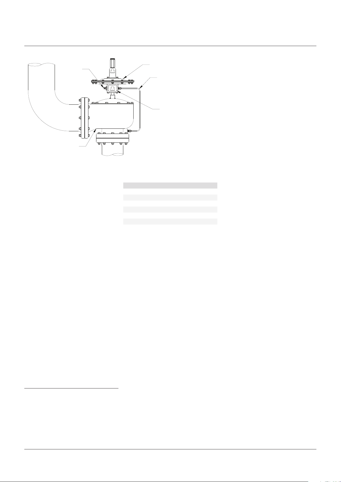
External
blowdown
Outlet
adjustment
Main valve
(typical)
Inlet
FIGURE 1
1.2 Installation
Both inlet and outlet may be standard ANSI or
DIN flange connections and are to be installed
in accordance with accepted piping practices.
The installed position of the safety valve should
be in the upright position as shown in Figure 1.
When remote pressure pick-up is used the pilot
supply tube is connected to a remote location
rather than to the inlet neck of the valve. If a
block valve is used in the remote pilot supply
line, be sure it is opened before pressurizing
the system.
Note: remote pressure pick-up piping must
have the equivalent flow area of ½” tubing for
lengths up to 20 feet. For lengths greater than
20 feet, larger tubing or pipe should be used.
1.3 Start-up
There must be pressure at the valve inlet
to establish a differential in force across
the diaphragm and “load” it in the closed
position. Pressure must pass through the pilot
supply tube and pilot and exert force on the
diaphragm. On normal start-up the valve loads
itself without incident as pressure increases.
Block valves are often used under safety valves
in order to isolate them when maintenance
is required. When putting the safety valve in
service be sure the block valve is fully opened.
If the block valve is opened after system startup, the safety valve may briefly vent to the
atmosphere before the dome gets pressurized.
It will then close.
2 MAIN VALVE MAINTENANCE (REFER TO
FIGURES 2 AND 2A)
2.1 Valve configuration
Two different valve internals are used in the
main valve, depending on set pressure. The
sponge seat is used for the set pressures
shown below. The O-ring seat with guide is
used for all pressures above these values. For
some applications, a guide may be used in
place of Item 11 with a sponge seat.
Pilot valve
Supply tube
Nameplate
SET PRESSURES WHERE SPONGE SEAT
ISUSED
Valve size Set pressure (psig)
2 x 3 Below 2.5 psig
3 x 4 Below 1.5 psig
4 x 6 Below 1.0 psig
6 x 8 Below 1.0 psig
8 x10 Below 1.0 psig
10 x12 Below 1.0 psig
12 x16 Below 1.0 psig
2.2 Disassembly
Disconnect the supply tube from the pilot,
remove the cap bolts, lift the cap from the valve
body and lift the diaphragm, seat and guide
(where used) from the valve. Remove the seat
bolt(s) to separate the diaphragm from the
seat, guide, and retainer plates.
2.3 Repair
Inspect the nozzle seating area for nicks or
scratches. If they cannot be removed with
crocus cloth or fine sandpaper, the nozzle must
be remachined. On steel valves the nozzle
may be removed from the body. Machining of
the nozzles should be limited to .06” material
removal.
2.4 Assembly
Reassemble the diaphragm, seat guide,
and pilot supply tube in the reverse order of
disassembly. Apply a light film of lubricant to
all threaded parts. Care should be taken to
adequately tighten the seat bolt(s) on those
valves with guides to prevent the diaphragm
from pulling away from the bolt under
pressure.
On valves with sponge seats (no guide), the
seat bolt need not be tightened as much since
these valves are used at lower pressures and
excessive tightening will distort the seat.
Carefully insert the guide (where used) squarely
into the nozzle and lower the diaphragm
assembly into place. Align the holes on the
diaphragm O.D. with those on the body.
The guide spring, Item 3, is used to create
frictional drag to prevent valve chatter caused
by excessive inlet piping pressure losses. The
tension of these springs is correct when the
diaphragm/guide assembly slowly free falls to
the closed position. If the assembly will not do
this, adjust the spring tension by bending the
tail or lower half of the spring.
Refer to paragraph 8 for Soft goods repair kits
2
ANDERSON GREENWOOD SERIES 93 POSITIVE PRESSURE POSRV
InstallatIon and MaIntenance InstructIons
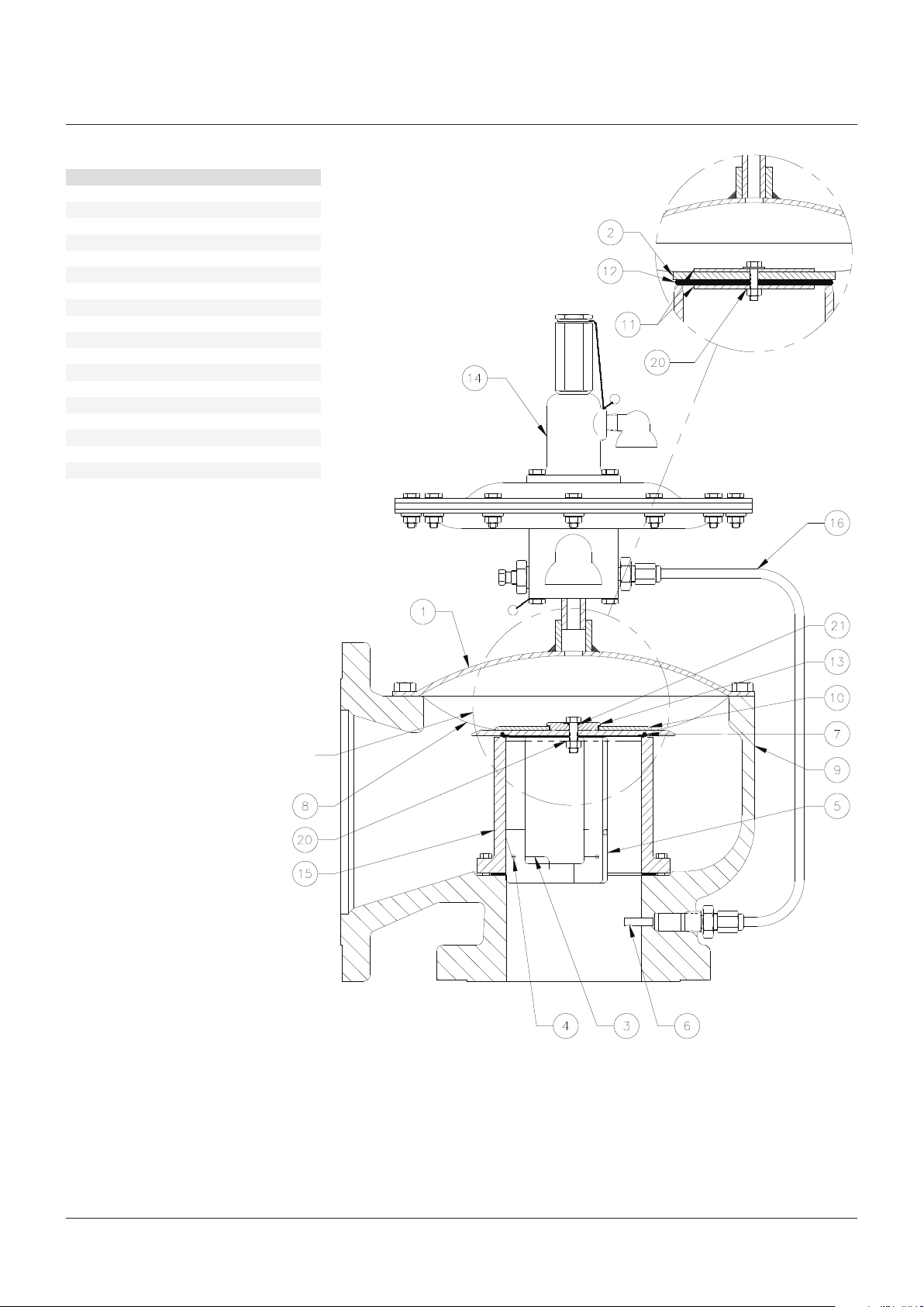
PARTS LIST
Item Description
1 Cap
2 Retainer plate
3 Guide spring
4 Spring pin
5 Guide
6 Dipper tube
7 O-ring, seat*
8 Diaphragm*
9 Body
10 Retainer, diaphragm
11 Seat retainer
12 Seat, sponge
13 Top plate
14 Pilot valve
15 Nozzle
16 Supply
20 Seal, thread**
21 O-ring*
1. Used in 8" and larger valves only
* Recommended spare parts for repair
** Used with elastomer diaphragms only
[1]
Sponge seat
(no guide)
See PTFE diaphragm
deflector detail next page
FIGURE 2
3