

Page 1
ACU-TROL® CHEMICAL CONTROLLER
FOR POOL AND SPA
MODEL AK110
Certied to
NS F/ANSI Standa rd 50
IMPORTANT SAFETY INSTRUCTIONS
READ AND FOLLOW ALL INSTRUCTIONS
SAVE THESE INSTRUCTIONS
INSTALLATION AND
USER’S GUIDE
Page 2

CUSTOMER SERVICE / TECHNICAL SUPPORT
If you have questions about ordering Pentair Aquatic Systems replacement parts, and pool products, please contact:
Customer Service and Technical Support, USA
(8 A.M. to 4:30 P.M. — Eastern/Pacific Times)
Phone: (800) 831-7133
Fax: (800) 284-4151
Web site
Visit www.pentairpool.com or www.staritepool.com
Sanford, North Carolina (8 A.M. to 4:30 P.M. ET)
Phone: (919) 566-8000
Fax: (919) 566-8920
Moorpark, California (8 A.M. to 5 P.M. PT)
Phone: (805) 553-5000 (Ext. 5591)
Fax: (805) 553-5515
2
Page 3

CONTENTS
SECTION 1 INFORMATION
IMPORTANT WARNING AND SAFETY INSTRUCTIONS ..............................................................5-6
CONTROLLER OVERVIEW . . . . . . . . . . . . . . . . . . . . . . . . . . . . . . . . . . . . . . . . . . . . . . . . . . . . . . . . . . . . . . . . . . . . . . . . . . . . . . . . . . . . .7
SECTION 2 INSTALLATION
INSTALLATION PREPARATION .................................................................................8
INSTALLATION SUMMARY .................................................................................8
MOUNTING INSTRUCTIONS ................................................................................9
ELECTRICAL SPECIFICATIONS .................................................................................10
INPUT VOLTAGE SELECTION. . . . . . . . . . . . . . . . . . . . . . . . . . . . . . . . . . . . . . . . . . . . . . . . . . . . . . . . . . . . . . . . . . . . . . . . . . . . . . . . .10
CONNECTING POWER .......................................................................................10
ELECTRICAL LOADS .......................................................................................11
RELAY BOARD. . . . . . . . . . . . . . . . . . . . . . . . . . . . . . . . . . . . . . . . . . . . . . . . . . . . . . . . . . . . . . . . . . . . . . . . . . . . . . . . . . . . . . . . . . . .12
CHEMICAL FEED PUMP LOCATION ...........................................................................13
HEATER INSTALLATION . . . . . . . . . . . . . . . . . . . . . . . . . . . . . . . . . . . . . . . . . . . . . . . . . . . . . . . . . . . . . . . . . . . . . . . . . . . . . . . . . . . .13
PLUMBING INSTALLATION. . . . . . . . . . . . . . . . . . . . . . . . . . . . . . . . . . . . . . . . . . . . . . . . . . . . . . . . . . . . . . . . . . . . . . . . . . . . . . . . . . . .14
SECTION 3 HARDWARE
MODULES . . . . . . . . . . . . . . . . . . . . . . . . . . . . . . . . . . . . . . . . . . . . . . . . . . . . . . . . . . . . . . . . . . . . . . . . . . . . . . . . . . . . . . . . . . . . . . . . .16
SENSOR MODULES .......................................................................................16
COMMUNICATION MODULES ...............................................................................16
RELAY MODULES .........................................................................................16
SECTION 4 AK1200 FLOW CELL
AK1200 FLOW CELL .........................................................................................18
FLOW CELL ASSEMBLY ....................................................................................19
FLOW CELL MOUNTING . . . . . . . . . . . . . . . . . . . . . . . . . . . . . . . . . . . . . . . . . . . . . . . . . . . . . . . . . . . . . . . . . . . . . . . . . . . . . . . . . . . .19
INLET AND EXIT LINES. . . . . . . . . . . . . . . . . . . . . . . . . . . . . . . . . . . . . . . . . . . . . . . . . . . . . . . . . . . . . . . . . . . . . . . . . . . . . . . . . . . . .19
SENSORS ...............................................................................................19
SECTION 5 SENSORS
pH AND ORP SENSORS ......................................................................................21
CALCULATED PPM ..........................................................................................22
AKCOLOR PPM .............................................................................................22
TEMPERATURE SENSOR ......................................................................................22
FLOW SENSORS . . . . . . . . . . . . . . . . . . . . . . . . . . . . . . . . . . . . . . . . . . . . . . . . . . . . . . . . . . . . . . . . . . . . . . . . . . . . . . . . . . . . . . . . . . . .22
SENSOR CARE .............................................................................................23
FINISHING AND TESTING THE INSTALLATION ....................................................................23
SECTION 6 OPERATIONS
CONTROLLER WINDOW NAVIGATION. . . . . . . . . . . . . . . . . . . . . . . . . . . . . . . . . . . . . . . . . . . . . . . . . . . . . . . . . . . . . . . . . . . . . . . . . . .24
SELECTING ITEMS IN THE WINDOWS ........................................................................25
MAKING CHANGES .......................................................................................25
START UP .................................................................................................26
INITIALIZING THE CONTROLLER. . . . . . . . . . . . . . . . . . . . . . . . . . . . . . . . . . . . . . . . . . . . . . . . . . . . . . . . . . . . . . . . . . . . . . . . . . . . . . . .26
POWER UP SCREEN .........................................................................................26
DISPLAY SCREEN ...........................................................................................27
THE DISPLAY SCREEN .......................................................................................27
CALIBRATING TEMPERATURE ...............................................................................27
CALIBRATING pH .........................................................................................28
CALIBRATING ORP ........................................................................................28
CALIBRATING CALCULATED PPM. . . . . . . . . . . . . . . . . . . . . . . . . . . . . . . . . . . . . . . . . . . . . . . . . . . . . . . . . . . . . . . . . . . . . . . . . . . . .29
MANUAL RELAY CONTROL . . . . . . . . . . . . . . . . . . . . . . . . . . . . . . . . . . . . . . . . . . . . . . . . . . . . . . . . . . . . . . . . . . . . . . . . . . . . . . . . .29
RELAY TIME DISPLAY ......................................................................................30
SET UP FLOW ............................................................................................30
CONFIGURATION MENU. . . . . . . . . . . . . . . . . . . . . . . . . . . . . . . . . . . . . . . . . . . . . . . . . . . . . . . . . . . . . . . . . . . . . . . . . . . . . . . . . . . .31
NAME ..................................................................................................32
SYSTEM ................................................................................................32
3
Page 4

CONTENTS (Continued)
PROGRAMMING .........................................................................................33
SERVICE ................................................................................................35
DATA . . . . . . . . . . . . . . . . . . . . . . . . . . . . . . . . . . . . . . . . . . . . . . . . . . . . . . . . . . . . . . . . . . . . . . . . . . . . . . . . . . . . . . . . . . . . . . . . . . .35
COMMUNICATIONS . . . . . . . . . . . . . . . . . . . . . . . . . . . . . . . . . . . . . . . . . . . . . . . . . . . . . . . . . . . . . . . . . . . . . . . . . . . . . . . . . . . . . . .36
PAGER SETUP SCREENS. . . . . . . . . . . . . . . . . . . . . . . . . . . . . . . . . . . . . . . . . . . . . . . . . . . . . . . . . . . . . . . . . . . . . . . . . . . . . . . . . . . .36
EMAIL SETUP ............................................................................................37
SECURITY ...............................................................................................37
WIZARDS ...............................................................................................38
SECTION 7 TROUBLESHOOTING
COMMON PROBLEMS .......................................................................................39
REAL TIME CLOCK ..........................................................................................39
ORP TROUBLESHOOTING . . . . . . . . . . . . . . . . . . . . . . . . . . . . . . . . . . . . . . . . . . . . . . . . . . . . . . . . . . . . . . . . . . . . . . . . . . . . . . . . . . . . .40
USING THE TEST STRIP ......................................................................................40
AKCOLOR PPM TROUBLESHOOTING ............................................................................41
pH TROUBLESHOOTING ......................................................................................41
SECTION 8 APPENDIXES
UTILITY PASSWORDS 9000-9020 ..............................................................................42
SET-UP DIGITAL FLOW .......................................................................................42
PROPORTIONAL FEED. . . . . . . . . . . . . . . . . . . . . . . . . . . . . . . . . . . . . . . . . . . . . . . . . . . . . . . . . . . . . . . . . . . . . . . . . . . . . . . . . . . . . . . .42
SECTION 9 WIRING DIAGRAMS
RELAY WIRING DIAGRAMS ...................................................................................43
SENSOR WIRING DIAGRAMS .................................................................................44
SECTION 10 MENUS
SCREEN NAVIGATION KEYS. . . . . . . . . . . . . . . . . . . . . . . . . . . . . . . . . . . . . . . . . . . . . . . . . . . . . . . . . . . . . . . . . . . . . . . . . . . . . . . . . . . . . . . . . . .45
MAIN STATUS SCREEN NAVIGATIONS ..........................................................................46
RELAY AND ALARM TIMER SCREEN NAVIGATION. . . . . . . . . . . . . . . . . . . . . . . . . . . . . . . . . . . . . . . . . . . . . . . . . . . . . . . . . . . . . . . . .50
CONFIGURATION MENU SCREEN NAVIGATION ...................................................................52
CONTROLLER NAME SCREEN NAVIGATION ......................................................................54
SYSTEM SETUP SCREEN NAVIGATION ..........................................................................56
PROGRAMMING SCREEN NAVIGATION , pH MIX TIME . . . . . . . . . . . . . . . . . . . . . . . . . . . . . . . . . . . . . . . . . . . . . . . . . . . . . . . . . . . . .58
PROGRAMMING SCREEN NAVIGATION, pH CYCLE TIME. . . . . . . . . . . . . . . . . . . . . . . . . . . . . . . . . . . . . . . . . . . . . . . . . . . . . . . . . . . .60
PROGRAMMING SCREEN NAVIGATION, ORP MIX TIME ............................................................62
PROGRAMMING SCREEN NAVIGATION, ORP CYCLE TIME ..........................................................66
PROGRAMMING SCREEN NAVIGATION, ORP CAL HYPO ............................................................70
PROGRAMMING SCREEN NAVIGATION, PPM CYCLE TIME ..........................................................74
PROGRAMMING SCREEN NAVIGATION, PMM MIX TIME ...........................................................78
PROGRAMMING SCREEN NAVIGATION, PROBE CLEAN. . . . . . . . . . . . . . . . . . . . . . . . . . . . . . . . . . . . . . . . . . . . . . . . . . . . . . . . . . . . .82
PROGRAMMING SCREEN NAVIGATION, HEATER ..................................................................84
PROGRAMMING SCREEN NAVIGATION, ALARM OUT ..............................................................96
PROGRAMMING SCREEN NAVIGATION, AUX. MAKE-UP (AUTO-FILL) ..................................................90
PROGRAMMING SCREEN NAVIGATION, DAILY EVENT .............................................................92
PROGRAMMING SCREEN NAVIGATION, WEEKLY EVENT. . . . . . . . . . . . . . . . . . . . . . . . . . . . . . . . . . . . . . . . . . . . . . . . . . . . . . . . . . . .96
PROGRAMMING SCREEN NAVIGATION, FRONT PANEL ALARM ......................................................96
PROGRAMMING SCREEN NAVIGATION, PAGER . . . . . . . . . . . . . . . . . . . . . . . . . . . . . . . . . . . . . . . . . . . . . . . . . . . . . . . . . . . . . . . . . . .100
PROGRAMMING SCREEN NAVIGATION, EMAIL ..................................................................104
WIZARDS SETUP SCREEN NAVIGATION . . . . . . . . . . . . . . . . . . . . . . . . . . . . . . . . . . . . . . . . . . . . . . . . . . . . . . . . . . . . . . . . . . . . . . . . .108
DATA SCREEN NAVIGATION. . . . . . . . . . . . . . . . . . . . . . . . . . . . . . . . . . . . . . . . . . . . . . . . . . . . . . . . . . . . . . . . . . . . . . . . . . . . . . . . . . .112
COMMUNICATIONS SCREEN DIAL-UP ..........................................................................114
COMMUNICATIONS SCREEN INTERNET MODEMS ................................................................118
SECURITY SETUP SCREEN NAVIGATION . . . . . . . . . . . . . . . . . . . . . . . . . . . . . . . . . . . . . . . . . . . . . . . . . . . . . . . . . . . . . . . . . . . . . . . . .124
AKCOLOR SCREEN NAVIGATION . . . . . . . . . . . . . . . . . . . . . . . . . . . . . . . . . . . . . . . . . . . . . . . . . . . . . . . . . . . . . . . . . . . . . . . . . . . . . . .126
SERVICE SCREEN NAVIGATION . . . . . . . . . . . . . . . . . . . . . . . . . . . . . . . . . . . . . . . . . . . . . . . . . . . . . . . . . . . . . . . . . . . . . . . . . . . . . . . .128
AK110 CHEMICAL CONTROLLER ILLUSTRATED PARTS LIST ..................................................130
4
Page 5
IMPORTANT WARNING AND SAFETY INSTRUCTIONS
SERIOUS BODILY INJURY OR DEATH CAN RESULT IF THIS PRODUCT IS NOT INSTALLED
AND USED CORRECTLY.
INSTALLERS, POOL OPERATORS AND POOL OWNERS MUST READ THESE WARNINGS AND
ALL INSTRUCTIONS BEFORE USING THIS PRODUCT.
Most states and local codes regulate the construction, installation, and operation of
public pools and spas, and the construction of residential pools and spas. It is important
to comply with these codes, many of which directly regulate the installation and use
of this product. Consult your local building and health codes for more information.
IMPORTANT NOTICE - Attention Installer: This Installation and User’s Guide
(“Guide”) contains important information about the installation, operation and safe use
of this product. This Guide should be given to the owner and/or operator of this product.
DO NOT INSTALL THE AK110 CHEMICAL CONTROLLER WHERE IT CAN BE READILY
ACCESSIBLE T O THE PUBLIC.
Before installing this product, read and follow all warning notices and instructions in this
Guide. Failure to follow warnings and instructions can result in severe injury, death, or
property damage. Call (800) 831-7133 for additional free copies of these instructions.
RISK OF ELECTRICAL SHOCK OR ELECTROCUTION:
BEFORE WORKING ON THE AK110 CHEMICAL CONTROLLER: Always disconnect power to the
AK110 controller at the circuit breaker before servicing. Failure to do so could
result in death or serious injury to service person, pool users or others due to electric
shock.
BE SURE TO DISCONNECT ALL SUPPLY CONNECTIONS BEFORE SERVICING.
This product must be installed by a licensed or certified electrician or a qualified pool professional in accordance
with the National Electrical Code (NEC), NFPA 70 or the Canadian Electrical Code (CEC), CSA C22.2. All
applicable local installation codes and ordinances must also be adhered to. Improper installation will create an
electrical hazard which could result in death or serious injury to pool users, installers or others due to electrical
shock, and may also cause damage to property.
BEFORE USING YOUR POOL, SPA OR HOT TUB, CHECK THE
pH AND SANITIZER LEVELS OF THE WATER
.
Do not permit children to operate this equipment.
When mixing acid with water, ALWAYS ADD ACID TO WATER. NEVER ADD WATER TO ACID.
When adding any chemical to the pool/spa, be sure to follow the manufacturer’s instructions
thoroughly.
DO NOT MIX SODIUM HYPOCHLORITE AND MURATIC ACID
Risk of electrical shock. Connect AK110 Chemical Controller to a ground-fault interrupter-circuit
(GFCI). Contact a qualified electrician if you cannot verify that the receptacle is protected by a
GFCI.
IF “CLEAR OVERFEED LIMIT” SETTING IS SET TO 24 HOURS, DO NOT SET “FEED TIME”
GREATER THAN 20 HOURS AS THIS WILL VOID NSF CERTIFICATION.
ACU-TROL® AK110 Chemical Controller Installation and User's Guide
5
Page 6
IMPORTANT WARNING AND SAFETY INSTRUCTIONS
WARNING CHEMICAL BURN HAZARD: Make sure all pumps are switched off at the main circuit
breakers at the house before drilling into any pipes. Securely fasten all electrical, water and
chemical lines. Locate chemical feed pumps and chemical storage tanks in a safe and secure
area.
Strictly follow the acid manuf acturers safety and handling protocols including hand, body and eye protection
when transferring or handling acid. Safety precautions should be used when handling Muriatic acid to
control pH water lev els. Muriatic acid can cause serious body injury and damage pool equipment. Extra
care must be taken when installing, maintaining and operating acid pump feed systems. Acid is dangerous to
handle and should be properly contained, transported, poured, stored, and dispensed.
Check the pH and sanitizer levels of the water before use.
Periodically use an independent pH and Chlorine test kit to verify that pH and chlorine is at a
safe level. If the pH and Oxidation Reduction Potential (ORP) or Flow Cell sensors are broken,
depleted or dirty with oils, lotions, or other contaminants, they can report inaccurate results to the
system causing incorrect water chemistry, which could harm people or equipment.
Check the main status display each day to ensure there are no Alarm messages.
See “Troubleshooting” section for more information.installing, maintaining and operating acid
pump feed systems. Acid is dangerous to handle and should be properly contained, transported,
poured, stored, and dispensed.
GENERAL WARNINGS AND SAFETY PRECATIONS
PLEASE READ THIS USER MANUAL completely before installing or operating the equipment. The Controller Pool and Spa Chemical Controller is a Class 1 product for protection against electric shock and a Type 1 product with regards to disconnection of the control circuits.
Be sure to observe the following safety precautions:
• Donotpermitanyoneuntrainedorundertheageof18tousethisproduct.
• Unitmustbeproperlygrounded.
• Frontpanelmustbeclosedbeforepowerisapplied.
• AlwaysturnOFFmaincircuitbreakertounitandallequipmentbeforeservicing.
• Touchingthecontroller’sinternalpartscouldresultininjuryandordamagetothecontroller.Incaseofa
malfunction, only a qualified technician should repair the controller.
• RiskofElectricShock.Connectonlytoagroundingtypereceptacleprotectedbyaground-faultcircuitinterrupter(GFCI).
• Donotburycord.Routecordtoeliminateexternaldamage.
• Becarefulnottodamageanyoftheinsulationonwiresorthepowercord.Shouldthecordbedamaged,returnittoyourdealerfor
a replacement. Continued use could result in fire or electric shock.
• Toreducetheriskofelectricshock,donotuseanextensioncordtoconnectunittoelectricsupply,providea
properly located GFCI.
• Neverremoveorinstallanycablesonthecircuitcardswhenpowerisapplied,damagetothecomponentsmay
occur.
!
WARNING
CHEMICAL BURN HAZARD
Make sure pumps are OFF before drilling into pipes.
Securely fasten all electrical, water and chemical lines. Locate chemical feed
pumps and chemical storage tanks in a safe and secure area.
CHEMICAL HAZARD CONDITION
DO NOT TURN CHEMICAL FEED PUMPS ON WHEN BOTH FLOW
ACU-TROL® AK110 Chemical Controller Installation and User's Guide
6
!
WARNING
CELL VALVES ARE CLOSED.
Page 7

AK110 Pool and Spa Chemical Controller Overview
The AK110PS Pool and Spa Chemical Controller ("Controller") is a microprocessor based modular automation system
capable of continuous local or remote monitoring and control of water chemistry for pool and spa applications. The
Controller will maintain the pH and sanitizer levels of your water system automatically. Customized applications are
possiblewiththeadditionofoptionalexpansionmodules.
MODULAR: The Controller is designed to grow with the needs of the customer. There are optional modules that can
be installed as the need arises without having to remove the Controller from the wall.
INTERFACE: The Controller uses a built-in keypad with 16 buttons, and an easy to read 80 character liquid crystal
display.Thedisplay’sinternalback-lightprovidesviewinginlowlightconditions.Theback-lightilluminationtimecanbe
adjustedtosuittheoperator.
MENUS:
The Controller features easy to use display menus for on screen navigation.
MEMORY:
In case of power loss, all set-points and programming are retained in nonvolatile memory. These values will
be protected for a minimum ten (10) years without having power applied.
DATA RECORDING: The Controller has the ability to record data at 2 hour time intervals. Over 1 month of data can be
recorded before filling up the memory. When the memory is full the new data will overwrite the oldest data.
RELAYS: The Controller can control up to three (3) relays. There are various types of relay configurations available to
different types of load requirements.
DISPLAYS: The Controller can display measurements, relay ON/OFF states, length of time that relays have been on
and the alarm status.
SENSORS: The Controller can measure readings and control based on inputs from the following sensors: temperature,
digital flow,
pH, ORP, and AKColor PPM.
VOLTAGE: The Controller includes a switch to select the input voltage of 110 or 220 VAC (single or dual phase).
HEALTH: The Controller can be configured to maintain the bacteriological and physiological requirements of state and
local health departments. In addition, the Controller has the capability to be configured such that equipment can be
protected from the effects of improper water balance.
REMOTE MONITORING:TheControllercanbeeasilyconguredforremote,fullduplexcommunicationusingan
internal 56K modem and a phone line, or a wireless modem and an internet connection. This feature allows a user
remote access to Controller operations using an MS Windows Based PC and the Acu-Com Software. The Acu-Com
Software is a full featured software package that allows the operator to download recorded data, monitor system
inputs in real time and provides a graphing option that allows for detailed analysis of water system parameters and
performance. In addition, AcuManage II, an online database management system will display data from any internet
enabled Controller.
REMOTE PAGING: With the optional modem installed, the Controller can be programmed to dial out to electronic
paging systems for notifying operators of an alarm condition.
REMOTE EMAILING: With the optional wireless modem installed, the Controller can be programmed to send an email
notifying operators of an alarm condition.
SECURITY: The Controller provides two level security protection based on passwords for both local and remote
interaction.
ACU-TROL® AK110 Chemical Controller Installation and User's Guide
7
Page 8

SECTION 2
INSTALLATION
Installation Preparation
Inspection: Upon receiving the Controller check the carton carefully.
Reportanyshippingdamagetoshippingcompany.Examinetheenclosedshippinglistandverifythatallitemsare
present. Contact Customer Support (800) 831.7133 if any items are missing or have been damaged. Use care when
unpacking equipment to avoid damage or loss of small parts. Verify that the fuses are the correct values and that the
voltage select switch is in the proper position.
Installation Summary
The following steps are required to install the Controller:
1. Identifynewandexistingequipmenttobeconnected.
2. Decide if the sensors will be in-line, in a separate by-pass line, or if the AK1200 flow cell will be used.
Caution:IftheAK1200owcellisused,theinputwatermaximumpressureis25PSI.
3. Determine the supply voltage, 110 VAC or 220 VAC, and set the supply voltage switch as necessary.
4. Determine if the control to the equipment uses the same voltage as the supply voltage.
All controlled equipment must be compatible.
5. Determine the water-tap points for the flow cell bypass inlet and outlet.
6. Mount the Controller away from direct sunlight and on a flat vertical surface.
7. Connect the supply voltage with main breaker off. (Must be a separate dedicated circuit GFCI).
8. If using an AK1200 flow cell install the bypass now.
9. Connect the sensors.
10. Test the plumbing for leaks.
11. Turn on the Controller for the first time.
12. Test the equipment, using the Controller manual relay mode.
13. Calibrate the probes, then re-calibrate as the probes acclimate to the system.
Acclimation can take as little as two hours or as long as 24 hours.
14. Program the Controller.
15. Callorvisitthecontrolleroverthenextfewdaystoinsurethesystemisbalancedandincontrol.
Fine-tune the setup if necessary.
ACU-TROL® AK110 Chemical Controller Installation and User's Guide
8
Page 9
Mounting Instructions
!
!
Select a location for mounting the Controller, meeting the following recommendations:
1. Mount at least ten (10) feet from open water.
2. Mount close enough for the supplied power cord to reach the supply voltage. The Controller will not operate
properly without a solid earth ground connection.
WARNING
Proper and safe operation requires an earth ground connection.
3. Supply power must be routed to the Controller in accordance with the applicable codes in the area; the
supplied power cord is not code in some areas.
4. The installation surface must be solid and vertical. Do not mount the Controller in a horizontal position.
WARNING
Keep the Controller out of direct sunlight, inside a room if possible.
Direct sunlight on the Controller will result in inaccurate readings.
A shade screen should be used for outdoor installations.
5. Maintain adequate clearance for opening the front panel enclosure.
6. Theenvironmentshouldbefreeofchemicalfumesandexcessiveheat.
Themaximumroomtemperatureisshouldnotexceed110ºF.
7. Mount as far as possible from sources of electrical interference.
8. Install the four mounting feet as desired to the Controller back and prepare the hole to the mounting
surface as desired.
9. Hold the Controller against the mounting surface with a closed lid and mark the location of the mounting
bracketlocatedonthetopoftheControllernexttothewall.Prepareholesasnecessaryandsecure
Controller using hardware provided.
10. Mountonaatsurface.Controllerboxwilldistortifmountedonanunevensurface.
11. Pre-install screws with ¼ left out on bottom so that the Controller can slide into them. Install the remaining
side screws and tighten.
ACU-TROL® AK110 Chemical Controller Installation and User's Guide
9
Page 10
Electrical Specications
!
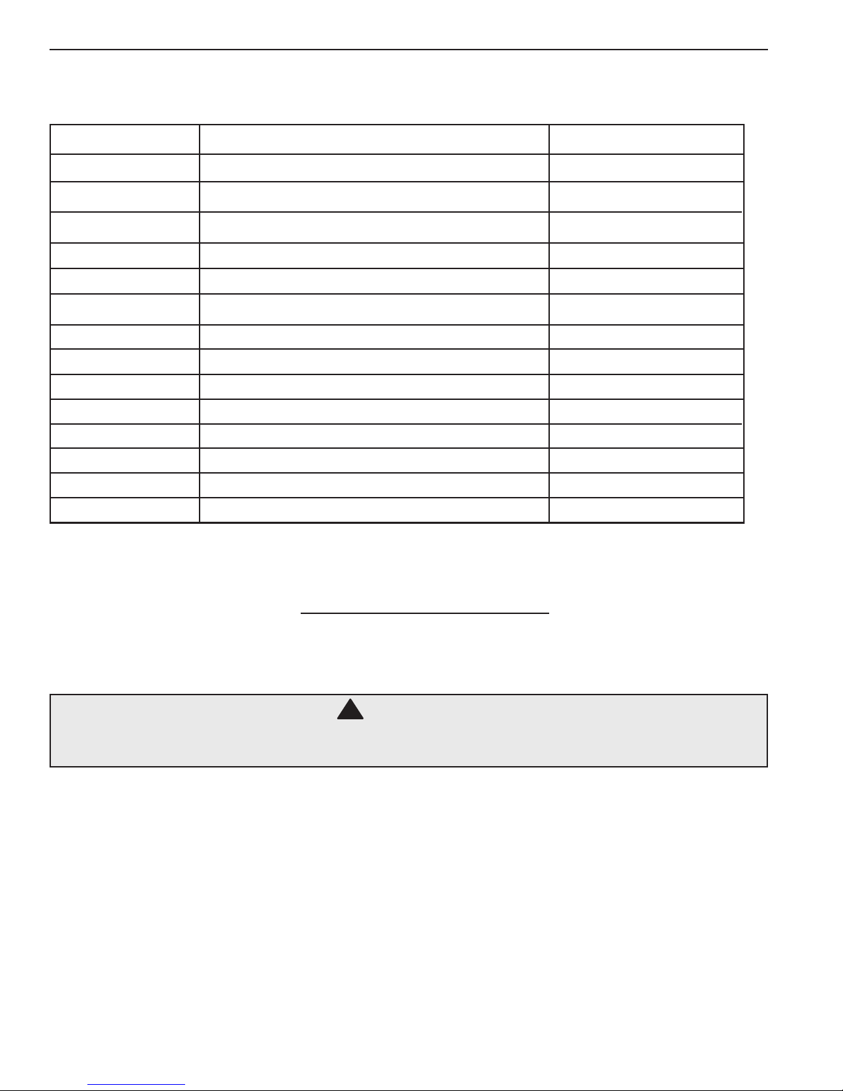
Thefollowingelectricalspecicationsinthetablebelowmustnotbeexceeded.
ITEM DESCRIPTION LIMIT
Input Voltage Maximum Input AC Voltage 250 VAC
Input Current Maximum Input Current 5 Amps (AC)
Output Current Maximum Current for 3 Relays 110V 5 Amps (AC)
Maximum Combined Current 3 Relays 24V Dry 1 Amp
Temperature Min./Max. Operating Temperature 30° - 110° F
Standby Current Current with all Relays OFF, LED ON 50mA (AC) Typical
Current with all Relays OFF, LED OFF 30mA (AC) Typical
Sensor Range pH 4.22 - 9.78
ORP 0 - 999mV
Temperature 32 - 212° F
PPM 0 - 8 PPM
Digital Flow 0 - 9999 GPM
Volume 0 - 65,535 Gallons
Flow Open or Closed
Input Voltage Selection
The Controller will operate on input voltages of 110 VAC or 220 VAC.
Thefactoryjumpersettingisfor110VAC.
The supply power is commonly used to power the feed pumps and
otherexternalloads.Ifalltheloadsare110VACthenuse110VACoriftheloadsare220VACthenuse220VAC
as the input voltage.
WARNING
If the Controller is connected to 220 VAC the voltage selection switch must be changed
to 220 VAC before connecting power to the unit or damage will occur.
Note: It is not possible to power the AK110 Chemical Controller with 110 VAC,
and control 220 VAC loads or vise versa.
Connecting Power
For cord connected installations wait to plug the cord in as the last step in the installation. For hard-wired installations
make sure the circuit breaker is off and turn it on as the last step in the installation. Have a licensed electrician perform
the installation to ensure the local codes are met.
ACU-TROL® AK110 Chemical Controller Installation and User's Guide
10
Page 11
Electrical Loads
!
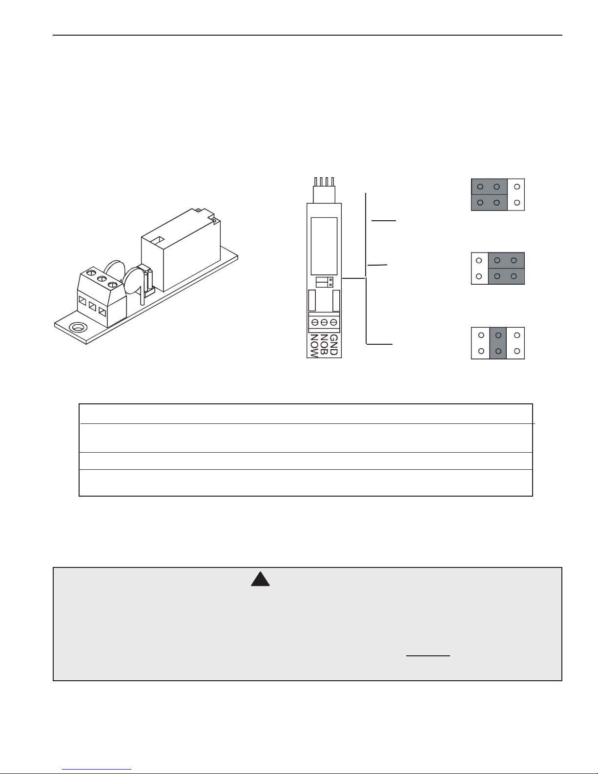
The Controller with revision F and greater relay board has the capability of utilizing up to three (3) modular relay boards
that can be purchased in a number of configurations. The Controller is shipped from the factory with three (3) 110 VAC
Normally Open modules installed (Part# 724000050). Listed below are the different types of relay modules that can
be purchased and their function. The correct ones must be ordered based on the load requirements. Check with your
distributor for the proper relay modules for your application.
Factory Setting
for input power
115 VAC
Setting for input
power 24VAC
Dry (Switch)
White = No Jumper
Grey = Jumper
Relay Modules
Part # FUNCTION
724000050 For control of 110 VAC Normally Open Circuits
(most applications will use this model).
724000060 For control of 110 VAC Normally Closed Circuits.
724000440 For control of 110 VAC Single Pole, Double Throw
Circuits, with common white and no ground.
The wiring on each board may be different depending on the model that you purchase. Look on the board, check with
your distributor or call Pentair Customer Support at 800-831-7133 with any questions.
WARNING
Do not change relay modules when power is applied.
This type of damage is not covered in the warranty.
Do not connect any load not rated for the supply voltage to any of these relays.
TOTAL COMBINED LOADS MUST BE LESS THAN FIVE (5) AMPS
FOR ALL THREE RELAYS.
ACU-TROL® AK110 Chemical Controller Installation and User's Guide
11
Page 12
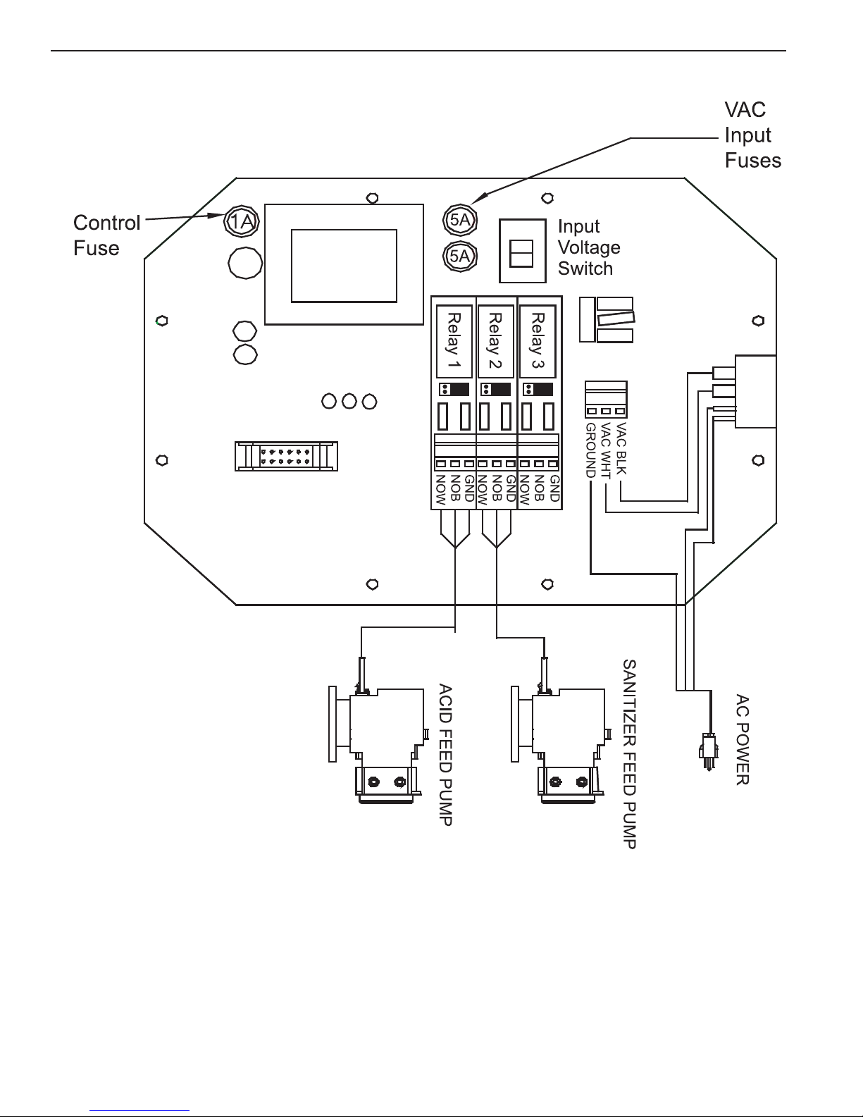
RELAY BOARD
115
Relay 1: Configured for pH control.
Relay 2: Configured for ORP control.
Relay 3: User configured.
ACU-TROL® AK110 Chemical Controller Installation and User's Guide
12
Page 13

Chemical Feed Pump Location
If unit has not been previously installed, follow the instructions included with the chemical feed pump. Some loads
include power cords already connected to the load and are ready to plug in. If “pigtails” have been ordered with the
Controller simply plug the power cord into the appropriate "pigtail". If "pigtails" are not installed the power cord from
the pump will need to be modified. The list below provides installation recommendations:
1. Mount at least 10 feet from open water.
2. Install the pump below the level of the Controller and away from any other equipment or systems.
This is to reduce any damage to other equipment should the pump leak.
3. Install close enough to the Controller for the feed pump power cords to reach.
4. If "pigtails" are included simply plug in the pumps to the appropriate "pigtail". If pigtails are not installed,
cut the electric plugs from the feed pumps and strip and ferrule the ends.
5. Route the power cords to the Controller through the lower fittings and attach to the appropriate relay
terminals on the relay circuit board. If the wire ends were striped and not ferruled make sure that no frays
of wire are out of the connector as this may lead to a short.
6. Conduitorexternalplugscanalsobeused(accordingtothecodesinthelocalarea).
7. When installing metal conduit into the Controller, a ground LUG should be used to connect the conduit to
the relay board ground.
Heater Installation
The Controller third relay can control a heater, turning it on and off based on the temperature settings you have
programmed in to the Controller. The heater control portion of the Controller can be used to maintain a constant
temperature or maintain a temperature during operating hours. Even though the Controller is a very accurate and
reliable device, for safety, always use the over-temp device on your heater to prevent overheating.
1. Always install any heater according to the manufacturer's instructions.
2. Mount the Controller at least 10 feet from open water.
3. Install close enough to the Controller for the wiring connections to reach.
4. DO NOT attempt to power the heater with the Controller controller.
5. A heater unit must always be independently powered, either through a separate cord, or through an
externalrelayliketheAcu-TrolHAR1relaymodule.(Part#735000060)
6. Always use the over-temp device on the heater to prevent overheating.
ACU-TROL® AK110 Chemical Controller Installation and User's Guide
13
Page 14

Plumbing Installation
!
WARNING
Be sure to have a licensed plumber perform all plumbing; this is important, as they will
be familiar with all of the codes in the local area.
Follow the instructions that came with the AK1200 flow cell. This section gives the basic principles to be applied for any
specific installation, which are listed as follows:
1. Turn OFF all equipment including the filtration system.
2. Determine a suitable location for the flow cell. Which should be located where water spillage will not
damage surroundings.
3. Securely mount the flow cell.
4. Install the supply and return lines for each flow cell. Drillandtap¼”holesforthe½”exibletubingorhard
plumb the flow cell.
A. Locate where the water will be supplied from and returned for each flow cell. The most common
location for the water inlet to the flow cell is after the main filter and the outlet after the heater.
B. If there is no suitable location the cell inlet can be after the main pump and the outlet before the main
pump. This method may cause a suction in the flow cell and damage to the sensors. If any chemicals
areinjectedintothecelltheymaycausetemporaryinvalidreadings.
5. Locatethechemicalinjectionpoints.
6. Prepareandinstallthechemicalinjectorttings.
7. Install the chemical storage containers.
8. Install the sensors.
9. Turn ON the main circulation pump.
10. Check for leaks and verify the flow sensor indicates flow.
ACU-TROL® AK110 Chemical Controller Installation and User's Guide
14
Page 15
Plumbing Installation
!
WARNING
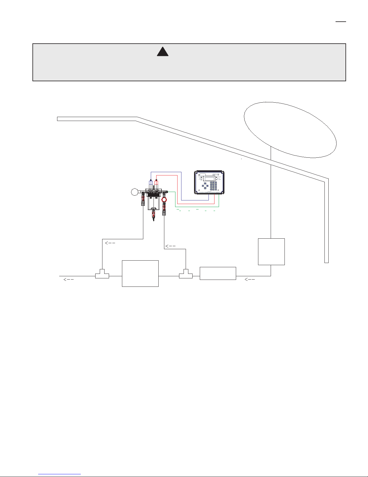
Do not inject acid directly in to the AK1200 ow cell.
Injecting acid in this way may damage the existing pool equipment.
Pool
Pump
Water
Return
Sample
Test
Supply
Preferred Plumbing Routes
ACU-TROL® AK110 Chemical Controller Installation and User's Guide
15
Page 16

SECTION 3
HARDWARE
Modules
Modules are the electronic controls and components that make up the Controller.
Each module has a specific function or functions that tell the Controller what information to accept and what
information to display. The modular design of the Controller enables it to interface with many types of modules
including Sensor, Communication, and Relay modules.
Sensor Modules
Sensor modules determine the types of sensors signals the control can recieve. There are three sensor modules
currently available for the Controller.
AK111: pH, ORP, temp and heater control. Calculated PPM can also be displayed (Part# 724000010).
AK112: pH, AKColor(PPM), heater control (Part# 724000380)
AK113SC: pH AKColor(PPM) ORP, Temp (Part # 725000390)
Communication Modules
The Controller has the ability to work with several types of communication modules. The Controller can communicate
with a PC through an RS232 cable, a standard modem, or a wireless modem.
Controller Modem: High-speed modem. (Part # 725000010)
Wireless Modem: The wireless modem allows the Controller to be accessed over the internet from any PC.
Wireless modems are a perfect solution for installations without phone lines. Please note that the wireless
modem and the standard modem can not be installed in the same Controller.
Relay Modules
The Controller is able to automate nearly any device in your pump room. The Controller uses a relay module to turn
electricity to the device on and off. Each Controller can control up to 3 relay modules. Each relay module can control
one device. Relay modules are available in seven different models. The type of relay module used depends on the
load requirements of the device that is controlled with the relay module. To determine the load requirements, please
consult the instruction manual or the device manufacturer. Any combination of the seven models of relay modules can
beinstalledinthethreeavailableslotsonarelayboard,aslongasthecombinationdoesnotexceedthecombined
maximumcurrentfortherelayboard.Thecombinedmaximumcurrentforanyindividualrelayboardis5amps.
ACU-TROL® AK110 Chemical Controller Installation and User's Guide
16
Page 17

Themaximumrelaycurrentfortherelayboardis5ampswhenswitching115VACor220VACand1ampswhen
switching 24 VAC.DRY
CONTACTS: These relays act as a dry contact switch only and have no connection to the input VAC. The relay ratings
are 5A and 250 VAC.
115 VAC Normally Closed: These relays supply the input voltage to the load when the relay is in the “OFF” mode.
Note that both VAC inputs are controlled by the relay. The relay ratings are 5A and 250 VAC.
115 VAC Normally Open: These relays supply the input voltage to the load when the relay is in the “ON” mode. Note
that both VAC inputs are controlled by the relay. The relay ratings are 5A and 250 VAC.
115 VAC SPDT: These relays are hard-wired selectable to be either NO (Normally Open) or NC (Normally Closed)
switching of the input voltage. They are always powered, and the wiring will dictate whether the power flows in the on
or off position. The relay ratings are 5A and 250 VAC. The neutral is common for both NO and NC.
24 VAC Normally Closed: These relays supply 24 VAC to the load when the relay is in the “OFF” mode. Note that both
VAC inputs are controlled by the relay. The relay ratings are 1A and 250 VAC.
24 VAC Normally Open: These relays supply 24 VAC to the load when the relay is in the “ON” mode. Note that both
VAC inputs are controlled by the relay. The relay ratings are 1A and 250 VAC.
24 VAC SPDT: These relays are hard-wired selectable to be either NO (Normally Open) or NC (Normally Closed)
switching of the 24 VAC. They are always powered, and the wiring will dictate whether the power flows in the on or off
position. The relay ratings are 1A and 250 VAC. The neutral is common for both NO and NC.
ACU-TROL® AK110 Chemical Controller Installation and User's Guide
17
Page 18
SECTION 4
AK1200 FLOW CELL
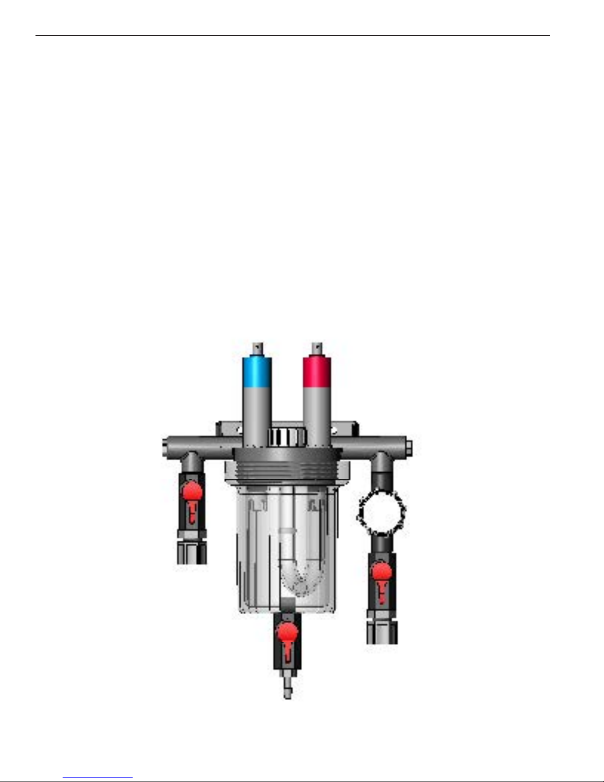
AK1200 Flow Cell
Remove flow cell from shipping carton and make sure all parts are included with AK1200 flow cell.
•1–AK1200Lid •1–AK1200JarwithO-Ring
•1–Flowswitchmagnet •3-¼”Valves.
•1-Samplebarbtting •4-¼”NPTby½”exttings.
•1-FilterassemblywithO-Ring •2-¼”plugs.
•1-FlowswitchwithO-Ring,2’ •1-¼”CloseNipple
and10’wirelengthsavailable. •1-Threaded Seal Tape
•2-Mountingscrews
Notethat½”exibletubingisnotincludedandissuppliedbytheinstallerormaybeorderedfromAcu-Trol.
ACU-TROL® AK110 Chemical Controller Installation and User's Guide
18
Page 19

Flow Cell Assembly
1. Wrapallfourexttingswiththreaded seal tape.
2. Installtwoexttingsintotwoballvalves.
3. Wrap barb fitting with threaded seal tape. Install barb into remaining ball valve.
4. Wrap both ends of the close-nipple with threaded seal tape. Install into the filter assembly using (either end OK).
Hand-tighten only.
5. Install one ball valve into the filter.
6. Install the filter and remaining ball valves as shown in the figure.
7. Verify that the flow switch magnet is in the flow cell tube with the large or hat end pointing down.
NOTE: Wrap fittings only twice around with threaded seal tape.
Flow Cell Mounting
Select a suitable location for the flow cell meeting the following recommendations:
1. Sensors wires will connect to within ten (10) feet.
2. Do not mount in direct sunlight. SUNLIGHT WILL CAUSE INACCURATE READINGS.
3. Water leaks will cause damage! Mount where water does not leak and damage other compentents.
4. Mount flow cell vertically with provided screws.
5. Securely fasten all electrical, water and chemical lines.
6. Locate chemical feed pumps and chemical storage tanks in a safe and secure area.
7. Maximumoperatingpressure=25psi
8. Extremepressurevariancesmayaffectreadingsandcancausedamagetothesensors.
9. Avoid installing the outlet before the main pump as the vacuum may damage the chemical sensors.
10. OnlyinjectchemicalsontheoutletsideoftheAK1200FlowCell
11. Do not over tighten fitting on flow cell top.
1. It is essential that the supply line be at a higher pressure than the discharge line so the water will flow through
the cell at a steady rate in the right direction. Installing a ball valve in the main circulation line may be required
if the pressure is too low.
2. Inlet should be installed after filter and before heater.
3. Exitshouldbeinstalledafterheaterandasfarawayfromanyequipmentaspossible.
4. Drill and tap at above locations with 7/16” drill and 1/4” NPT tap. Choose a location on a fitting where the
pipeenterssoyouaredrillingthroughboththepipeandttingtogetmaximumdepthofthread.
5. Install¼”NPTby½”exttingsthenrouteinletandexitlines.
Inlet and Exit Lines
ACU-TROL® AK110 Chemical Controller Installation and User's Guide
19
Page 20
Sensors
!
!
1. pH and ORP sensors must remain wet at all times. Install the sensors into the flow cell,
HAND-TIGHTEN ONLY and save caps for future use and fill flow cell with water.
2. Route the flow switch wires into the Controller through the strain relief and connect to the Controller.
Wire one (either one) to ground and one to the appropriate input switch.
3. Route the chemical sensors into the Controller through the strain relief and connect to the Controller.
The sensor wires are labeled and the PLUS AND MINUS POLARITY MUST BE OBSERVED.
4. Turn the main pump on and open the valves to test for leaks and the free movement of magnet.
Magnet must be all the way up in order to close the flow switch. 1/4 GPM will push the magnet all the
way up.
CAUTION
The ow switch is a dry contact only (no current).
Use with any other brand Controller VOIDS WARRANTY.
WARNING:
Make sure all pumps are OFF before drilling into pipes.
Never turn chemical feed pumps ON when both
ow cell valves are closed.
ACU-TROL® AK110 Chemical Controller Installation and User's Guide
20
Page 21

SECTION 5
!
SENSORS
The Controller can accept readings from a wide variety of sensors. The sensors the Controller can read depends on
the sensor module installed in the Controller. Each sensor has its own unique circuitry that is connected directly to the
micro-Controller for measurement. Isolation of each sensor ensures more accurate measurements.
The Controller measures the following sensor measurements with the listed characteristics:
pH - Range: 4.22 to 9.78
ORP - Range: 0 to 999 mV
Temperature - Range: 32 to 212 °F
Flow Switch: This input measures if a switch is open or closed.
WARNING
Sensors are shipped with a protective cap covering the electrode tip to protect
the sensing element. Sensors should be kept in the protective cap until ready for
installation, if the sponge in the boot becomes dry, wet it with pool water.
Before using the sensor remove the cap.
pH and ORP Sensors
pH electrodes sense the acidity of the water and work with any acid or base. The blue bands on the cables identify the
pH sensors. The red bands on the cables identify ORP sensors. Each sensor is also identified on the sensor body. ORP
electrodesareusedtomonitortheOxidationReductionPotential(ORPissanitizationqualityofthewater)ofagiven
solution. The sensing element of the ORP electrode is made of a precious metal such as platinum or gold.
THE POLARITY (+ AND -) OF THE pH AND ORP SENSORS MUST BE OBSERVED. The ORP sensor (+) copper and the pH
sensor(+)copper,andthegreenleadsare(-)polaritylabeled.LeaveexcesswireoutsidetheControllerenclosure.Ifthe
cable is longer than needed, it should be coiled neatly and attached under the Controller enclosure.
DO NOT CUT THE SENSOR WIRES.
Do not stuff excess wire inside the controller as this may cause excess strain
on sensor and relay connections.
ACU-TROL® AK110 Chemical Controller Installation and User's Guide
21
Page 22

Calculated PPM
If you have an ORP sensor module you can choose to operate the AK110 in Calculated PPM (Parts Per Million) mode.
When in Calculated PPM mode, the Controller uses a special formula to convert the ORP reading from the sensor in to
PPMunits.ToactivatetheCalculatedPPMmode,select"PPM,MixTime"or"PPM,CycleTime"inthewizardsection.
Note when you are in Calculated PPM mode ORP will not be displayed on any screens. See page 78 for PPM Cycle time
menu tree.
AKColor PPM Sensor
TheAKCOLORisacolorimetricmethodchlorineanalyzerdesignedtoworkinconjunctionwithmostAcu-Trol®
Controllers. The AKColor is capable of measuring the amount of free chlorine present in a body of water. The colormetric
method of measuring PPM is superior to other methods because it is much less sensitive to varying water conditions,
including pH and salinity. The information gathered by the AK Color can be used to control chemical feed pumps and
signal alarm conditions. For more information on the AKColor please see Navigation Screen on page 128 or consult your
AKCOLOR installation manual.
Temperature Sensor
The AK10K sensor can be installed to measure/display temperature. The sensor should be installed as close as possible
to where the water comes from the pool. If a temperature probe is installed in the AK1200 flow cell there will be a
temperature variation due to the long tubes and the temperature in the pump room. A common place to install it is in the
small plugged hole in the bottom of the main pump strainer basket.
The sensor uses a special ¼” NPT fitting to hold the stainless steel sensor. A hole should be drilled (7/16”) and tapped
(1/4”) where the water enters the pump room through a fitting to get double the depth to hold the sensor. If installed
outdoors make sure to keep it out of direct sunlight. Route the wires into the Controller through a strain relief and
connect to the temperature input. The red wire goes to T and the black wire to GND.
Flow Sensors
The Controller has the capability of measuring two flow switches in which one or both can be a digital flow sensor.
These inputs are general purpose and can measure any dry contact switch state. This can include flow, pressure,
temperature, digital flow rate and so on.
The typical uses for the flow switches are:
Switch
1: Typically used to indicate flow through the flow cell and it is OK to feed chemicals. If a digital sensor is
used the actual flow rate can be measured and displayed in gallons/liters per hour.
Switch 2: Can be used to measure water level for automatic level control. If a digital sensor is used the actual
flow can be measured and displayed in gallons / liters per hour.
NOTE:
To obtain liters per minute the scale factor must be changed to pulses per liter.
ACU-TROL® AK110 Chemical Controller Installation and User's Guide
22
Page 23

Sensor Care
!
Contamination of the sensing elements often results in slow response and inaccurate readings. Clean the elements by
the following procedures:
pH and ORP Sensors
1. Wash electrode tip in a liquid detergent and water. Carefully use a soft bristled toothbrush to wash the
electrode tip and white sensing ring.
2. Rinse after cleaning. To install, place in flow cell according to the diagram and hand tighten.
3. Make sure the O-ring is installed on sensor.
4. If the cable is longer than needed, it should be coiled neatly and attached under the cabinet.
pH Sensors Only
5. Attempt to clean the sensor with liquid detergent first.
6. If this is not successful, swirl the tip of the sensor in a 5 parts water and 1 part muriatic acid solution
for 10 - 20 seconds.
7. Rinse again and reinstall.
WARNING
Do not rub hard the glass element in the sensor or use sand paper or
other polishing material to clean.
HANDLE ELECTRODE CAREFULLY
Sensors contain external and internal glass elements. Do not drop or otherwise
subject the sensor to vibration, physical impact, or freezing conditions.
ANY TYPE OF BREAKAGE IS NOT COVERED UNDER WARRANTY.
Finishing and Testing the Installation
OncetheControllersystemhasbeeninstalledwithapplicablesensorsandexpansionmodulesthefollowingstepsare
required for final system finishing and testing.
1. After all wire connections are complete close the panel and tighten the enclosure.
2. Plug in the Controller and turn on the main breaker. Switch the ON/Off switch to ON.
Up is ON and down is OFF.
3. Verify that the display is active and displays various introduction/initialization screens.
4. SENSORS: The first screen displays the sensor readings, verify that they are connected properly.
Example: pH is within 0.5. This is to verify that the pH is connected to the pH input and
the ORP is connected to the ORP input.
5. FLOW: Verify that the flow switch indicates on (S1ON) and the green flow LED is on. Close the valve
in the flow cell to stop the flow and verify that the Controller indicates no flow (S1OFF) and the flow
LED is off.
6. LOADS: Leave the valve closed (S1OFF) for this part of the test so that the relay programs will keep
relays "automatically" off. Press the Right button 1 time to R1 (ph) OFF and press ENTER to "manually"
turn on the load, verify that the correct load turns on and press enter to turn it off.
Pressthedownarrowtoselectthenextrelayandrepeatfortheothertworelays.
ACU-TROL® AK110 Chemical Controller Installation and User's Guide
23
Page 24
SECTION 6
FLOW
ALARM
POWER
SECURITY
Made in USA
110/220 VAC. 5A Disconnect Power Source Before Servicing Unit
AK110
87 9
54 6
21 3
Back
0
Enter
OPERATION
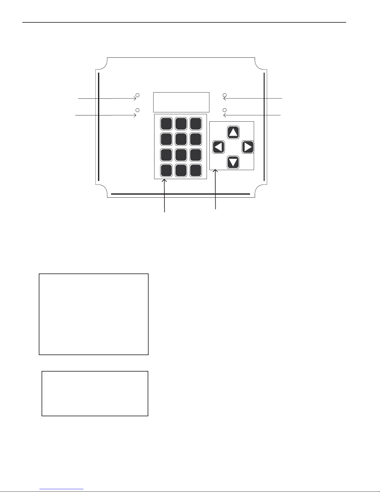
FLOW
INDICATOR LIGHTS
Flow is on when light
is lit.
Alarm
Indicator Lights
Light is lit when a
warning or alarm
condition occurs.
ALPHANUMERIC KEYPAD
Used to enter numeric parameter settings, alphabetic charac-
ters, and special shortcuts for commonly used menus.
POWER
INDICATOR LIGHT
Power is on when light is lit.
SECURITY
INDICATOR LIGHT
Light is lit when password
protection is active
ARROW BUTTONS
Up/ Down/ Left/ Right arrow buttons move you
through the AK110's menus.
.
Conguration Menu Screen
>Name:Main Pool
System
Programming
Service
Data ( 8:441 )
Communications
Security Setup
Wizards
Serial # 123456
Main Status, cursor at pH value
pH > 7.67-OFF 7.50s
ORP 490 -OFF 700s
_____
69.0f SW1OFFSW2OFF
Window Navigation
This section introduces window navigating and how to
edit and modify the Controller settings and programs
usingguidelinesandexamplesforselectingandchanging
items.
The Controller provides two main screens for user
operations:
1. Display Screen: for monitoring measurements,
calibrating and manually turning on relays. This is the list
that displays at startup.
2. Menu List: for editing and setup of parameters.
24
ACU-TROL® AK110 Chemical Controller Installation and User's Guide
Page 25
Selecting Items in the Windows
!
The 16-button touch pad is used to access and modify the different Controller functions:
•PressingtheBACKbuttononthetouchpadwillmovebackonewindow.
•PressingtheBACKbuttonwilltogglebetweenDISPLAYSCREENandMENULIST.Ifthe"REDsecuritylight"is
on a password must be entered to access MENU LIST.
•Pressingthearrowbuttonswillrepositionthecursoronthescreen.TheUPorDOWNarrowbuttonswillscroll
up or down the screens and the RIGHT and LEFT will move arrows to the RIGHT and LEFT on the screen
See page 48 for more detailed navigation instructions.
WARNING
Press 16 Button touch pad with nger pads only. A sharp object such as a
pen or tool will damage button pads.
MAKING CHANGES
To change a parameter move the cursor to the parameter and press the ENTER key. The Controller will then open the
value entry screen for that parameter. The Controller navigation system uses the following considerations:
1. Use the right and left arrows to change to a different digit to enter.
2. Press a number on the keypad to change a digit.
3. Press the left button to add a digit and make the number bigger.
4. Press the ENTER button to save the change.
NOTE
Changes must be saved by pressing the nal ENTER.
If ENTER is not pressed as the last step the changes with not be saved.
ACU-TROL® AK110 Chemical Controller Installation and User's Guide
25
Page 26
Start Up
The following steps need to be performed to properly setup the Controller:
1. Perform any required calibrations.
2. Decidetousemixingtimecontrolorcycletimecontrol.
3. Set up the timing parameters based on the size of the water and chemical feeding system.
4. If the AKRTC (Real Time Clock) module is installed set the time, date and weekday. (Part # 724000280)
5. Set the overfeed time limits in programming.
6. Return as needed to recalibrate any changes to the settings
7. If the AK540 modem (Part# 725000010) is installed, then set the number
of rings to answer on and setup the paging conditions.
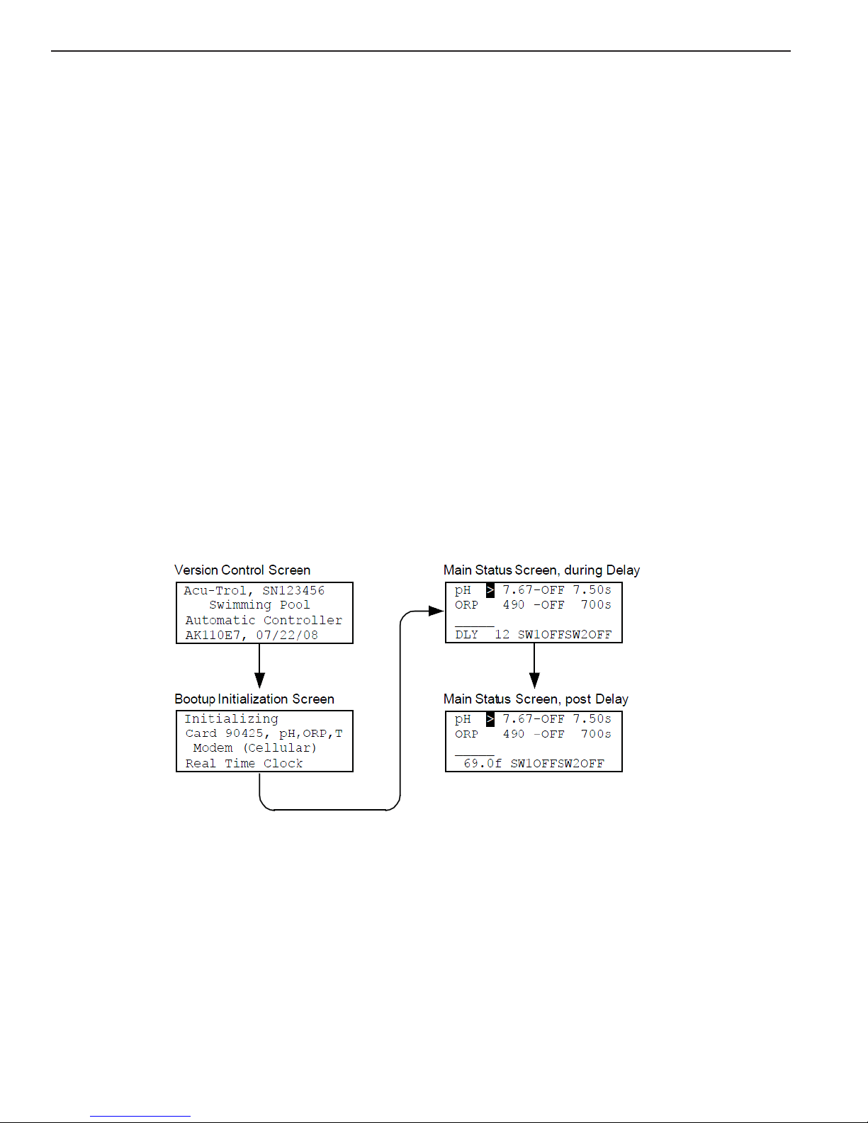
Initializing the AK110PS Pool and Spa Chemical Controller
During power-up the Controller will display the Power Up Screens for a few seconds before defaulting to the Display
Screen. During this Power On Self Test mode, the Controller will perform a brief check of its internal systems and
initializetheinternal(RAM)memoryforControlleroperation.NexttheControllerwillautodetectforthevarious
installed modules and indicate which ones are detected. The opening screen includes the software version number and
will be required when requesting support. When turning on a number will be displayed in the lower left corner of the
display screen indicating how many seconds until control will actually start. This is to allow time for the sensor readings
to stabilize.
Power Up Screens
Display Screen
Display Screen: Displays measurements of connected sensors and also relay status. To the right of the Sensor readings are also displayed the set point values. To change set points you will need to go to programming and change them
there. Pressing the Up Arrow key when the curser is at the top of the readings screen will move you back to the opening
screen.
ACU-TROL® AK110 Chemical Controller Installation and User's Guide
26
Page 27

The Display Screen
The DISPLAY SCREEN shows all the current measurements, as well as the
user programmed set points. It allows access to specific types of information
including the current measurements. Press the arrows on the touch pad to
scroll up or down or left or right as indicated by moving the > Cursor on the
screen.
Calibration: Position the cursor to the left of any of the three measurements
and press ENTER to calibrate that sensor. A value entry screen will then be
opened. Enter the calibrated value with the numeric key pad. To save your
changeandexitthevalueentryscreen,presstheenterbutton.Tocleara
specific calibration press "0" on the touch pad when the cursor is in front of
the value (The reading may not go to a zero reading but it will default to the
sensors uncalibrated reading).
Manually turn on relays: The relays in the Controller are represented on the
displayscreennexttoitscorrespondingsensorreading.Positionthecursor
to the left of the status word (either OFF or ON) and press ENTER to toggle
therelayonandoff.Thelengthoftimetherelayisonisadjustableinthe
programming. When the relay is toggled to off the relay
immediately goes back to automatic control and in some cases may turn back
on immediately.
Main Status, cursor
at pH Relay
pH 7.67>OFF 7.50s
ORP 490 -OFF 700s
_____
69.0f SW1OFFSW2OFF
Calibrating Temperature
The temperature sensor is very accurate and should not require calibration. If the calibration is more than a couple
degrees off there may be an installation problem. The most common problems with temperature sensors are listed
below:
1. The most common temperature problem is the temperature is not the same at the sensor as it is in the main
body of water. It is also possible the temperature error is different depending on the time of day. Make sure the sensor
is not in direct sunlight, and is installed as far into the fitting and as close as possible to the body of water. Evaluate
where the sensor is installed.
2. The sensor may be damaged. If the sensor is put in a room of 76°F the resistance should be 10,000 OHM's
that can be measured with a standard voltmeter. To calibrate the temperature sensor move the cursor in front of the
temperature reading and press ENTER. Enter the measured value. Press ENTER again to save the calibration change.
Calibrating pH
Measure the pH using a standard test kit by taking several readings and averaging the results. To calibrate the pH
sensor move the cursor to pH and press ENTER. Enter the value obtained from the test kit in to the value entry screen.
Press ENTER again to save your changes.
ACU-TROL® AK110 Chemical Controller Installation and User's Guide
27
Page 28

Calibrating ORP
!
WARNING
Always make sure the pH is at the set point before calibrating ORP. Always control
at PPM levels greater than 1.0 PPM when using ORP sensors.
IMPORTANT:
For best results the ORP should be at the ORP set point when calibrating.
For best results the PPM should be at the desired level when calibrating ORP.
Measure the current PPM
using a standard test kit. Calibrating ORP is intuitive and takes a little practice. The following
table can be used to improve the accuracy of the calibration. Follow the recommendations in the table and within a few
days the PPM should be on track. The values of interest are:
Measured PPM: The hand measurement.
Desired PPM: The actual PPM that is desired in the pool.
ORP: The value of ORP that is displayed on the screen.
ORP Set point: The value of ORP that the Controller is trying to achieve.
Hand PPM ORP Display Action
Low
Perfect
Above hand
check
At hand check
Below hand
check
Above hand
check
Calibrate to hand check measurement: 10mV per each
PPM Low
Review Setpoints: May need to increase chemical feed
times
Calibrate to hand check measurement: 10mV per each
PPM Low
May need to decrease chemical feed times & calibrate to
hand check
At hand check No changes
Below hand
check
High
ACU-TROL® AK110 Chemical Controller Installation and User's Guide
28
Above hand
check
At hand check Lower the set point
Below hand
check
Calibrate to the hand check
May need to decrease chemical feed times & calibrate to
hand check
Calibrate to hand check measurement: 10mV per each
PPM High
Page 29
Calibrating ORP
!
EXAMPLE 1: The default set point is 700, the PPM
hand measurement is 1.0 (2.0 PPM desired), and the current
display shows a measurement of 690 mV. From the above table the hand PPM is low and the ORP is below the set
point. The chemical feed times are not high enough for the ORP to reach the set point and should be increased.
EXAMPLE2:Fromexample1changethehandmeasurementto4.0PPMwithORPreading700mV.Fromtheabove
table the hand PPM is high and the ORPisbelowthesetpoint.TheORPshouldbecalibratedto700+(4.0–2.0)*10=
720.To compare ORP measurements to PPM measurements per actual pH readings refer to the calculated PPM chart on
page 131.
Calibrating Calculated PPM
If you have an ORP sensor module and Calculated PPM mode selected. You can calibrate the Calculated PPM in the
following manner. Measure the PPM using a standard test kit. To calibrate the PPM, move the cursor to PPM and press
ENTER. Enter the value obtained from the test kit in the value entry screen. Press ENTER again to save your changes.
NOTE
You can enter the password 9003 to see the ORP and adjusted ORP being
used for calculated PPM. These ORP values will only be displayed for four
(4) seconds.
WARNING
Always make sure the pH is at the pH setpoint and PPM is greater than
1.5 PPM before calibrating calculated PPM.
Always control at PPM levels greater than 1.0 PPM when using
ORP sensors.
MANUAL RELAY CONTROL
Display Screens
Position the cursor to the left of the status word and press
ENTER
to toggle the relay on and off. The length of time the
relaystaysonisadjustableintheprogramming.Whenthe
relay is toggled to OFF the relay immediately goes back to
automatic control and in some cases may immediately turn
ON.
back
Main Status, cursor
at pH Relay
pH 7.67>OFF 7.50s
ORP 490 -OFF 700s
_____
69.0f SW1OFFSW2OFF
ACU-TROL® AK110 Chemical Controller Installation and User's Guide
29
Page 30

RELAY TIMER DISPLAY
The Relay Timer display indicates the present status of the 8 timers
used in the Controller. The most common use for this screen is to
perform diagnostics on a specific relay or to see how long a relay
has been on. From the DISPLAY SCREEN press the right arrow button
twice. Press the left arrow button to return to readings screen.
Timer Screen, Relay 1 (pH)
pH, Mix TMR00:00:00
>TD00:00:00
CNT: 0 S 00:00:00
STS:OFF TOT 0:00
Note: To reset the relay timers to zero use the right button to scroll the cursor beside the information that you want to
reset and then press the ENTER button.
• TMR:Displaysrelaytimer.Showstimeremainingforrelayontime.
This timer will be counting with off and on cycles. Counting down when ON cycle, counting up when OFF cycle.
• TD:DisplaysthetimetheMPShasbeenONforthecurrentday(ToDay).
• CNT:Totalnumberofrelaycyclessincelastreset.
• S:Setoverfeedtimer,lengthofrelayontimewithoutreachingsetpoint.
• STS:StatusofrelayON,OFF,SetPointOverfeed(SOV),Overfeed(OVF),andDisable(DIS).
• TOT:DisplaysthetotaltimetheMPShasbeenONsincelastresetinhours:minutes.
SETUP FLOW
To use a switch as a digital flow switch you must first set it up. To enter the setup screen from the DISPLAY SCREEN
move the cursor to the switch "SW_" to be setup and press ENTER. You can enter the number of pulses per gallon from
1 to 999.9. This second method should only be used for flow meters that generate less than one pulse per gallon.
The highest volume that can be accumulated from the flow rate is 65,535 gallons.
Flow can also be displayed in g/pul and Piezo.
NOTE: Switch 1 is the default ow switch for relay control and should not be used for digital ow if switch 2 is
available.
Flow Switch 2 Setup
Flow Switch #2
SW2 K => 8.5 pul/g
g/m = 35
Total = 256 Clear
NOTE: If k = 0 than g/m = and Total = will not be displayed on the screen.
ACU-TROL® AK110 Chemical Controller Installation and User's Guide
30
Page 31

To clear the Total, for any switch place the cursor on Clear
and press ENTER.
When entering pulses per gallon the Controller will only
update this measurement once every 10 seconds.
Conguration Menu
The Configuration Menu consists of the following:
Flow Switch 2 Setup, Clear Counter
Flow Switch #2
SW2 K => 8.5 pul/g
g/m = 35
Total = 0 >Clear
Note:
• Name:Setsupthenameofyouraquaticsystemforeasy
identification during communication and on the wireless
data management system. See pages 56 for Controller
Name Navigation Menu Tree.
Conguration Menu Screen
>Name:Main Pool
System
Programming
Service
Data ( 8:441 )
• System:Setsuptime,date,weekday,andunitdisplay
(English or Metric). See pages 58 or System Set-up Screen
Navigation.
• Programming:RelayprogrammingforRelays1,2,3,Alarm,andPagers.SeeProgramming
Section for details. See pages 52-109 for Programming Set-up Menus.
• Service:Clearcalibrations,data,orrelaytimersaspartofnormalserviceoperations.
• Data:Sensorreadingsarerecordedatadefault2hoursintodata.Atotalof441linesofdatacanbe
stored. Press the down arrow key to view data. See page 114 for Data Screen Navigation.
• Communications:Setupmodems,pagernumbersandoremailaddresses.Seepages102-105for
Programming Screen Navigation Pager 1. See page 116 for Communications Screen for Dail-up and
Internet Modems. See pages 106 for Programming Screen Navigation Email.
Communications
Security Setup
Wizards
Serial # 123456
• SecuritySetup:Setsuppasswords,clearspasswords,andresetsallsettingstofactorydefaults.
See pages 126 for Security Setup Screen Naviagtions.
• Wizards:Selectpre-writtenprogramsforcommonControllerapplications.
See pages 110 for Wizards Setup Screen Navigation.
• Serial#:Viewtheserialnumberhere.Theserialnumberisrequiredwhenrequestingsupport.
ACU-TROL® AK110 Chemical Controller Installation and User's Guide
31
Page 32

Name
The Name Setup submenu allows the system controlled by the Controller to be specifically identified on the Controller
and in its communication with other devices. The name of the Controller is particularly useful when using remote
communication devices such as the standard and wireless modem. Naming each aquatic system, pool, or spa will make
it easier to identify each Controller and verify its location before making modifications to the system.
The alphanumeric characters that make up the system name are entered using the touch-pad. You have a full range of
letters, numbers and symbols available to aid you in uniquely identifying each system under your control.
System
Opens a menu where time, date and day can be changed.
• Time:Timeofday;placecursornexttoTIMEselectENTER to set time in hours, minutes, seconds.
• Date:OptionalwithRealTimeClockModule.(Part#724000280)
Date must be set when Real Time Clock is installed. If not installed date with default to 00:00:00.
• Day:OptionalwithRealTimeClockModule.DaymustbesetwhenRealTimeClockisinstalled.
If not installed day with default to 00:00:00.
• Units:SelecttotogglebetweenMetricandEnglishunits.Whenmetricisselectedthedateisdd/mm/yy,
when English is selected the date format is mm/dd/yy.
• Sanitizer:Selectbetween“Cl”(chlorine)and“Br”(bromine).
• OnDelay:PressingEnteronthislineincrements(by15)thenumberofsecondstherelayswillbeoffon
power up.
• BacklightTime:SelecttheamountoftimetheControllerscreenbacklightwillbeoneachtimethecontrol
panel is activated.
• TempDisplay:Displayswatertemperatureinfarnihietdegrees.Toturntemperaturesensoroff,toggleon/off
and select enter.
• ResettoDefault:ReturnsControllertooriginalfactorydefaultsettings.
ACU-TROL® AK110 Chemical Controller Installation and User's Guide
32
Page 33

Programming
The Programming menu provides sub-menus used to
configure and view the three output relays, alarm,
and 4 pagers as appropriate. To edit a program use
the up and down arrows to position curser and press
ENTER.
Below are the edit option screens for pH. Use the up
and down arrow to position the curser in front of the
option to be edited.
Edit Settings: Place the cursor to the desired location to
edit the values. Setting a value equal to zero will disable
thatcommand.Forexample,theOffifSwOffcommandis
disabled in the program below. To enable this command
change the "No" to "Yes".
Manual Time: The amount of time the relay will turn on during
a manual cycle. This will occur each time the manual cycle is
activated.
Proportional: The percentage of the set point where the
Controller will begin automatically shortening the length of
the feed cycle to prevent the Controller from over shooting
the set point. To turn off the proportional feed function, enter
"0" as the proportional feed percentage.
Programming Setup Screen
>>1:pH, Mix Time
2:ORP, Mix Time
3:Not Used
A:Alarm
P:Pager1
P:Pager2
P:Pager3
P:Pager4
pH Mix Time Programming Screen
ManualTime 00:02:00<
Proportional% 10
On If pH> 7.50
On If pH< 0.00
Off if RLY On 2
On DELAY 00:00:20
On Time 00:01:00
MinTimeOff 00:05:00
Off if Sw1 Off-YES
Off if Sw2 On -NO
SetOvrfeed 00:00:00
Overfeed 01:00:00
Example:5isenteredastheproportionalfeed%.Thismeans
that the Controller will automatically shorten the length of
thefeedcycleoncethemeasuredreadingiswithin5%ofthe
set point. If the pH set point is set at 7.50, the proportional
feed will begin to limit the feed cycle at 7.87 and continue
to shorten the feed cycle each time it feeds until set point is
reached. For best results, the proportional feed percentage
should be kept between 0 and 5 percent.
ACU-TROL® AK110 Chemical Controller Installation and User's Guide
33
Page 34

Programming
On If pH>: Acid Feed: the set point value at which the Controller will begin to feed acid or other pH chemicals to the water
source. Set this value to zero if not using acid to control the pH.
On If pH<: Base Feed: the set point value at which the Controller will begin to feed base or other pH chemicals to the water
source. Set this value to zero if not using base to control the pH.
Off if RLy on(#): Number of relay (1 or 2) will display. Depending on which relay is on the other relay will remain off. Prevents
bothrelaysfromcomingonatthesametimeandmixingChlorineandMuriaticAcid.
OnDelay:ThisisabuiltintimerwhichpreventstheControllerfromprematurelymixingchemicalsstillinthesystemorwhen
suctionsidechemicalfeedingisused.Thispreventstherelayfromturningonwhilechemicalsaremixinginthesystem.
OnTime:MaximumamountoftimethattheControllerwilldispensechemicals.
Min Time Off: Minimum amount of time that the Controller will be off before it will dispense any more chemicals, regardless
of the set point reading.
Off if Sw_Off: Tells the Controller not to dispense any chemicals if this switch number is in an OFF condition. This prevents a
large amount of chemicals from being added into the water line as flow of water returns.
Set Point Overfeed: If a relay output is "ON"accumulativeforlongerthanthesetpointoverfeed'smaximumtimeallowedthe
reading screen will display a “SOV” (Set Point Overfeed) on relay display. (This is to keep the Controller from continuously
feeding chemicals in case the sensor has a problem or if there is a clog in the feed tubes or you run out of chemicals). This
control condition will automatically reset itself if the sensors set point value is reached.
Overfeed:Thisvalueshouldbesetforthemaximumaccumulated“ON” time that the Controller will be allowed to feed each
chemical in a 24 hour period. If the Controller's “ON”timeexceedsthetotalallowed"ON" time within a 24-hour period the
Controller will disable the associated feed relay, and not feed any more of that chemical until the overfeed timers are cleared
manually, or until the Controller automatically resets the overfeed timers at the end of its 24 hour day. Each relay output used
tocontrolafeedsystemwillhaveitsownoverfeedsettings.Exceedingtheoverfeedtimerscanbesettocauseanalarm
condition. If the overfeed time alarm condition persists over a few days you may need to check the chemical container levels,
Controller feeder problems or you may need to increase the overfeed time to a level that will allow the Controller to maintain
the water quality levels within your specified limits. If the system does go into an overfeed condition along with the alarm LED
coming on, it will also display an "OVR" statement in the display screen, for the relay output that was in an overfeed condition.
Overfeed for 01:15:00 or 01:30:00, in case there was a problem with the feeder, chemicals or the sensor that are in overfeed
condition, the Controller would disable feed and alert a problem.
NOTE: The Controller's Overfeed feature is equivalent to the amount of time the chemical feeders will feed during
an alarm condition.
OPR Indicating
Overfeed Condition
Timer Screen, Clear
Overfeed
pH 7.67>OFF 7.50s
ORP 490 -OVR 700s
_____
69.0f SW1OFFSW2OFF
ACU-TROL® AK110 Chemical Controller Installation and User's Guide
34
ORP, Mix TMR00:00:00
>TD01:30:00
CNT: 0 S 00:00:00
STS:OVR TOT 0:00
Page 35

Programming
To manually reset the Overfeed Timer be sure that the cursor is
beside the TD Reading and press the ENTER button.
This will reset the timer to zero.
Service
All Off 10 min (NO) Press the Enter button to turn all three relays off for 10 minutes. This feature is useful when calibrating. After selecting the display will change to (YES) selecting the line again will remove the "All OFF" condition.
•ClearCalibrations:Clearsallpreviouslyenteredcalibrations
•ClearData:Erasesalloftheexistingdata.
•ClearRelayTimers:Resetsalltimerstozeroforallrelays.
Data
Sensor readings are recorded every 2 hours into the data log. Up to 12 lines of data can be recorded a day. The
Controller will save up to 441 lines of data in its data log. When the data log is full the oldest records will be over
written.
The default data log includes the day of operation, the hour sequence, and the sensor readings. When used in
conjuctionwitharealtimeclock,dataincludesdateandhourandsensorreadings.Pressingthedownarrowkeyto
view subsequence data.
When downloading the data with a PC the following information will also be displayed:
Title=MPBPF123:Modem,PCRS232, Front Button pressed, Password entered, Flow S1 on, and relays 1-3 status.
ACU-TROL® AK110 Chemical Controller Installation and User's Guide
35
Page 36

Communications
The followings are only available if the modem is purchased and installed.
Modem: Sets up the number of rings to answer on and the long hang up time. If you enter the password 9000 you can
access the modem diagnostic screen. On the modem diagnostic screen you will see the modem initialization string that
was returned by the modem during startup. This string should end with the word “OK” for working modems.
Pager Test: Tests pagers and displays paging status. To test the pagers, simply Press ENTER while in this screen. The
screen displays which pager is being paged and its counting down time. If the paged modem (pager company) is not
answering,theControllermodemwillhangupwithin40seconds,andthemodemisreset,readyforthenextpage.You
can press the BACK button at any time to cancel the testing process.
Pager Setup Screens
Pager Numbers: Sets up the pager numbers. The programming setup screen will display up to four pager numbers.
This will allow the system to page up to four numbers to alert more than one technician when a pool problem arises.
The process to enter pager numbers in the AK110 is as follows:
1. Press BACK button to reach MAIN Screen.
2. Scroll down to Communications
3. Press ENTER to select Communications
4. Scroll down to pager numbers and press ENTER to select pager numbers
5. Select the #1 pager number location.
6.Usingthekeypadtoenterpagernumber.Usingcursorarrowstomovetothenextnumberandsoon.(Thekeypad
worksexactlylikeacellphonekeypadandenteringinformationasyouwouldaphonenumberinyourcellphone
address book). See AK110 Programming Screen Navigation on page 88 for details on alarms. Make sure to enter the
"comma" to allow enough delay time for the modem on the other end to pick up. Each comma is worth 4 seconds
of time. Use the 0 button to toggle the ',', '-', and '#' for pager editing. Press ENTER to save the changes. Here is an
exampleforapagernumberentry:18005552222,,9014910,,911#.Theactualpagernumberisyourphonenumber.You
determineacode(example:911forchemicaloverfeed)dependingonwhatyouwantthepagertodeneasaproblem.
Thestringalwaysendswitha‘#’sign.IfamistakeismadepressUPtodelete.PressDOWNtoabortentry.SeeAK110
Programming Screen Navigatioin, Pager 1 and 2 for details on page 102.
ACU-TROL® AK110 Chemical Controller Installation and User's Guide
36
Page 37

Email Set-up
Email addresses:
The programming setup screen will display up to four email addresses. This will allow the system to email up to four
addresses to alert more than one technician when a pool problem arises. The process to enter email address in the
AK110 is as follows:
1. Press BACK button to reach MAIN Screen.
2. Scroll down to Communications
3. Press ENTER to select Communications
4. Scroll down to Email addresses and press ENTER to select Email addresses
5. Select the #1 email address location.
6.Usingthekeypadtoenteremailaddress.Usingcursorarrowstomovetothenextletterandsoon.(Thekey
padworksexactlylikeacellphonekeypadandenteringinformationasyouwouldaphonenumberinyourcellphone
addressbook).Ifyouremailaddressistolongforthespacesavailableusethenextavailableemailaddresstocompletetheaddress.Add"+02"totheendoftheaddresswhereyouneedtobreaktothenextline.
Example:email1:johndoe@+02
email 2: myserver.com
See page 106 for more detailed email set-up process.
Up to two levels of security may be implemented on the AK110 Controller.
1. Master Password: The master password enables access to all controller functions and menus. A master password
maybeimplementedaloneorinconjuntionwithaservicepassword.
2. Service Password: The more limited Service password allows access to sensor calibrations screens from the
Main Status Screen. A service password may be implemented only after a master password has been implemented.
Passwords consist of up to nine digits.
Password restrictions:
1. The password may not be begin with a zero (0) as the first digit.
2. The security password must be in the range of "1" and "8999" and "9011 and "999999999".
The numbers 9000-9010 are reserved for technical support purposes and may not be used.
3. A master password is required for should a wireless modem be installed in the AK110.
See page 126 for the AK110 Security Set-up Screen Navigation for more detailed security set-up process.
Security
ACU-TROL® AK110 Chemical Controller Installation and User's Guide
37
Page 38

Wizards
When leaving an editing screen you will need to confirm the changes by pressing “9” or cancel by pressing press "7".
Also after making any changes be sure to press the "Back" button until you reach the main menu screen. Otherwise your
changes will not be saved.
The following list shows all the "Wizards" available with the Controller:
Control options for pH Relay 1
1. pH,MixTime–usetocontrolapHfeedsystem.
2. pH,CycleTime–usetocontrolapHfeedsystem.
3. NotUsed–usetodisablethisrelay
Control options for ORP/PPM Relay 2
1. ORP/PPM,MixTime–usetocontrolasanitizerfeedsystem.
2. ORP/PPM,CycleTime–usetocontrolasanitizerfeedsystem.
3. ORP, Cal Hypo - use to control Cal Hypo feed system
4. Not Used - select to disable this relay.
5. PPM,Mixtime-usethecalculatedPPMfeatures
6. PPM, Cycle time, use the calculated PPM features
Control options for Relay 3
1. Not Used - select to disable this relay.
2. Probe Clean - use to introduce acid for a short time to clean sensors.
3. Heater-Usedtocontroltemperaturewithanexternalheater.
4. AlarmOut-externalalarmcontrol.
5. pH,MixTime-usedforadditionalpHcontrol(i.e.whenbothAcidandBaseareneeded.
6. pH, Cycle Time - optional method see program.
7. AUX: Make UP - control a make-up water system (auto fill).
8. Daily - turns on relay once per day
9. Weekly - turns on relay once per day on selected day(s) of the week.
10. ORP/PPMMixTime-useforadditionalsanitizercontrol
(i.e. when a liquid feed system is used to back up a salt generator).
11. ORP/PPM, Cycle Time - optional method see program.
Control options for Pager/Email 1-4
1. Pager 1-4/Email 1-4
2. Not Used
See page 110 for the AK110 Wizards Setup Screen Navigation
ACU-TROL® AK110 Chemical Controller Installation and User's Guide
38
Page 39

SECTION 7
TROUBLESHOOTING
COMMON PROBLEMS
PART PROBLEM SOLUTION #1 SOLUTION #2
Alarm High pH alarm on Increase ON time (CO2)
Check chemical tank
= slower reaction,
needs more time ON.
and make sure it is
not empty.
Flow Cell Magnet will not go up Clean lter on ow cell. Back wash main lter
or increase ow.
ORP/pH
Probe
Readings bounce Clean probe, check
ground on input power.
Reduce ow through
ow cell.
Flow Switch Not working Check for magnet. Check for debris in
ow cell.
Alarm Overfeed alarm on Increase overfeed time. Make sure feeder is
working properly.
Program Relay 1 & 2 not
turning ON but work
manually
Make sure ow switch
is closed. Very that
the green ow light is
Check set points.
turned on.
The Real Time Clock
The Real Time Clock (RTC) is an optional module (PN# 724000280) that allows time display and time stamps in the data
log. The Controller will automatically detect the real time clock when it is installed. The real time clock is battery powered, with a minimum of 5 years battery life.
ACU-TROL® AK110 Chemical Controller Installation and User's Guide
39
Page 40

ORP Troubleshooting
ORP Calibration Actions
Hand PPM ORP Display Action
Low Above Set point Cal to below set point: 10mV per each PPM
Check flow and/or clean sensor.
At Set point Cal to below set point: 10mV per each PPM
Below Set point May need to increase chemical feed times.
Perfect Above Set point > 6 May need to decrease chemical feed times.
Calibrate to the set point.
At Set point ±5 No changes
Below Set point >6 Calibrate to the set point.
High Above Set point Decrease chemical feed times.
At Set point Cal to above set point:10mV per each PPM
Below Set point Cal to above set point: 10mV per each PPM
Check flow and/or clean sensor.
EXAMPLE: The default set point is 700, the PPM hand measurement is 1.0 (2.0 PPM desired), and the current display shows a measurement of 690 mV. From the above table the hand PPM is low and the ORP is
below the set point. The chemical feed times are not high enough for the ORP to reach the set point and
should be increased.
To compare ORP measurements to PPM measurements per actual pH readings refer to the calculated PPM
chart on page 131.
Using the Test Strip
1. Remove all wires from the sensor card.
2. Insert test strip into the green terminal bar on the sensor card.
Match the pH test strip side to the sensor card side
3. Reset the calibrations with the test strip installed.
4. Call Acu-Trol Technical Support at 800-273-4667 with the sensor readings if your results do not match
the following readings:
ORP 90350-28A pH = 7.65-7.75 ORP = 485-500 Temp = 68.0-71.0
PPM 90350-35A pH = 7.65-7.75 Color = TBD Temp = 68.0-71.0
ACU-TROL® AK110 Chemical Controller Installation and User's Guide
40
Page 41

AKColor PPM Troubleshooting
Problem Solution
PPM Reading is 0 or 9.99 1. Check Flow to AKColor Flow Chamber
2. Check Chemical Levels
3. Check Discharge from DPD and
Buffer Solenoids
4. Clear Calibrations
Chemical Reagents are being 1. Check sample rate, decrease to 5 min or used too
quickly greater.
2. Check the DPD and Buffer solenoids for leaks
Measured PPM Level is lower 1. Check sample flow solenoid for leaks
than the hand check reading 2. Recalibrate the PPM reading with pH at
setpoint.
Theclearvoltageisnot3.5 1.AdjustthepotentiometerintheAKColor
pH Troubleshooting
Problem Solution
pH not reading correctly 1. Use the test strip to verify pH
2. Confirm that the BNC sensor wires are
installed correctly
3. Install a new BNC sensor wire.
4. Check the manufacture date of the sensor
5. Confirm that the flow rate in the AK1200 Flow Cell is between
0.5 and 1.5 liters per minute.
pH readings response slow to
to changes in the water 1. Confirm that there is flow in the Flow Cell
2. Clean the pH sensor using the Acu-Trol pH
sensor or cleaning procedure listed in this manual.
pH readings inaccurate 1. Recalibrate the pH reading
ACU-TROL® AK110 Chemical Controller Installation and User's Guide
41
Page 42

SECTION 8
APPENDIXES
Utility Passwords 9000-9010
From the Main Status screen press [4] to enter the password screen.
9001– Enteroncefor1-seconddatarecordingrate.Enterasecondtimefor5-minutedatarecordingrate.
To go back to the default 2-hour recording sample rate, power the unit off and then back on.
9003– Whenin“CalculatedPPM”mode,showstheactualORPandtheadjustedORPderivedfrom
Calculated PPM calibrations.
Set Up Digital Flow
To use Switch 1 or Switch 2 as a digital flow switch you must first set it up in the flow switch set-up screen. To enter
the setup screen from the MAIN SCREEN, move the cursor to the switch “S” to be setup and press ENTER. Enter the
number of pulses per gallon from 0 to 999.9. NOTE: Switch 1 is the default flow switch for relay control and should not
be used for digital flow if switch 2 is available.
To clear the total accumulate flow counter, place the cursor to CLEAR and press ENTER.
Proportional Feed
The proportional feed value determines the ratio of feed ON time in a cycle. The general principle is that a relay should
beonforareducedamountoftimeasitnearssetpointsoastominimizechemicalfeedovershoot.Alagtimeexists
between the time the chemical feeds and the sensors "read" the new values. Older Controllers would have a relay on
continuouslywhichcanleadtosignicantovershootingofthechemicalfeed.TheControlleradjusttheratiobasedon
howfarfromthesetpointisfromthemeasurement.Thefollowingtablesshowsexamplesoffeedtimesforvarious
conditions:
Set
Point
Measurement
Prop %
Actual On
Actual Off Cycle
700 630 10% 00:06:00 00:00:00 00:06:00
700 631 10% 00:05:54 00:00:06 00:06:00
700 698 10% 00:00:06 00:05:54 00:06:00
700 665 10% 00:03:00 00:03:00 00:06:00
700 100 10% 00:05:06 00:00:54 00:06:00
700 699 10% 00:06:00 00:00:00 00:06:00
Table 3. ORP Control with the Cycle Time control type.
Cycletime=6minutes
ACU-TROL® AK110 Chemical Controller Installation and User's Guide
42
Page 43

SECTION 9
WIRING DIAGRAMS
Relay Wiring Diagram
Back View of the Switch
Black wire from
Green Terminal
Bar
White wire from
Green Terminal
Bar
Black wire to
Power
Supply
White to Power Supply
Black to Power Supply
Ground
Normally Open
(NO) Relay
To 110 VAC Outlet
White Wire to
Power Supply
Green Wire To GND
Black Wire to NOB
White Wire to NOW
OR
Normally Closed
(NC) Relay
(Optional)
Green Wire to GND
Black Wire to NCB
White Wire to NCW
Use Optional
Acu-Trol Pigtails
or Gangbox
ACU-TROL® AK110 Chemical Controller Installation and User's Guide
Sanitizer
Feed
Pump
Acid
Feed
Pump
43
Page 44

Sensor Wiring Diagram
AK110PS Chemical Controller Top View
AK110PS Chemical Controller Bottom View
Control Board
Green Terminal Bar
+12
GND
Switch 2
Switch 1
GND
Sensor Card
Green Terminal Bar
pH -
pH +
ORP -
ORP +
GND
TEMP
Flow
Switch
pH
Sensor
ORP
Sensor
pH Sensor Wires
=GreentopH=CoppertopH+
ORP Sensor Wires
=GreentoORP-
=CoppertoORP+
Flow Switch Wires
=RedtoGND
=BlacktoSwitch1
ACU-TROL® AK110 Chemical Controller Installation and User's Guide
44
Page 45

SECTION 10
MENUS
SCREEN NAVIGATION KEYS
For basic Controller operations, follow the screen navigation keys. The arrows guide you to each level and provide you
examplesoftheinformationbasedontheconditionofyourpool.TheactualinformationontheControllerscreenwill
differfromthemenuexamples.TheLCDback-lightturnsofffollowingauser-denedperiodofinactivity.Pressanykey
to turn the on back-light. The LCD screen displays 4 horizontal rows at a time. Many menus consist of five or more lines.
Use the up or down arrow keys to navigate through longer menus to display additional menu options on-screen.
PLEASE CALL 800-831-7133 FOR TECHNICAL ASSISTANCE.
NOTE:
The keypads on the mounted AK110 Chemical Controller do not have the letter of the alphabet
or numbers printed on the keypad.
The some models curser keys do not have "Delete", "To Right", "Cancel"
or "To Left" printed on the keys.
Using the AK110 Keypad to Name the Controller
7
4
G H I
1
!$%^&*+
0
,-#.@_
Each numeric key is associated with three
or more letters of the alphabet, or with
punctuation and other special characters.
Successive keypresses cyc l e t h r o ugh the
various characters associat e d with ea ch
key. For instance, p r e ss t he [ 5] ke y o n ce
to display the number "5" on-screen.
Press it a second ti me ( wh i l e t he cursor i s
in the same position) t o d i sp l a y t h e l e t t er
"J". The third keypress displays the letter
"K" and the fourth keypress displays the
letter "L". Press the key o n e m ore time t o
return to the number "5".
8 9
T U V
W X Y ZP Q R S
5
J K L
M N O
2
A B C
Insert
D E F
ENTERBACK
Confirm
DELETE
6
L
E
F
T
3
CANCEL
Each of the arrow keys as well as the
[Back] and [Enter] keys pe r fo r m sp ec i fi c
functions within th e Controller N a m e
Screen.
Press the up arrow key t o d el e t e t h e
character at the cursor position.
Press the left arrow key t o mo v e t h e
cursor one space to t h e l e ft .
Press the right arrow k e y t o m ov e t h e
cursor one spa ce t o t he r i g ht.
Press the down arrow k ey t o c ancel out of
the controller namin g p r o ce ss.
Press the [Back] key to i n ser t a bla nk
space at the cursor position.
Press the [Enter] key to co nfi rm the
controller name as displayed on-screen.
Press "ENTER"
at the end of each
programming
session to save the
changes. If "ENTER" is not
pressed the AK110
will default back to
R
I
G
H
T
the original
saved changes.
ACU-TROL® AK110 Chemical Controller Installation and User's Guide
45
Page 46

pH 7.67-OFF 7.50s
ORP 490 >OFF 700s
_____
Main Status, ORP Relay is Off
Back
To Timer Screen, pH. Refer to
AK110 Relay and Alarm Timer
Screen Navigation
10.1
AK110 Relay and Alarm Timer
Screen Navigation
Note:
The LCD Backlight turns off following a
user-defined period of inactivity. Press
any key to turn the backlight on.
The LCD screen displays 4 horizontal
rows at a time. Many menus consist of 5
or more lines. Use the up and down
arrow keys to navigate through longer
menus to display additional menu options
on-screen.
To Timer Screen, pH. Refer to
Acu-Trol, SN123456
Version Control Screen
Swimming Pool
Key
"Any"
Automatic Controller
AK110E7, 07/22/08
Enter new value
Current: 7.67
7.67
Calibration Scr een, p H
Main Status, cu r sor at pH valu e
v-Cancel ^
Enter
ORP 490 -OFF 700s
_____
69.0f SW1OFFSW2OFF
pH > 7.67-OFF 7.50s
Back
Enter
pH 7.67>OFF 7.50s
ORP 490 -OFF 700s
_____
Use the keypad t o en t er the
calibrated pH value.
Main Status, pH Relay is Off
Press the [Enter] key to confirm or
the down arrow key to cancel.
69.0f SW1OFFSW2OFF
Main Status, pH R elay tu r n ed O n
pH 7.67>ON 7.50s
ORP 490 -OFF 700s
_____
69.0f SW1OFFSW2OFF
Press the [Enter] key to manually
Enter new value
Current: 490
490
Enter
pH 7.67-OFF 7.50s
ORP > 490 –OFF 700s
_____
v-Cancel ^
Use the keypad t o en t er the
69.0f SW1OFFSW2OFF
turn the control relay o n o r o ff. I f
no flow is detected, a warning /
verification screen will first appear.
Calibration S creen, O RP
Main Status, cur sor at ORP value
calibrated ORP value.
Press the [Enter] key to confirm or
the down arrow key to cancel.
AK110 Main Status Screen Navigation (1 of 2)
46
Back
Service
>Name:Main Pool
Configuration Menu S creen
Data ( 8:441 )
System
Programming
Communications
Security Setup
Wizards
Serial # 123456
Page 47

pH 7.67-OFF 7.50s
AK110 Main Status Screen Navigation, Rev 3 21 Aug 2008
Main Status, ORP Relay is Off
To Timer Screen, pH. Refer to
AK110 Relay and Alarm Timer
ORP 490 >OFF 700s
_____
Screen Navigation
Back
69.0f SW1OFFSW2OFF
Enter
pH 7.67-OFF 7.50s
Main Status, ORP Relay turned O n
ORP 490 >ON 700s
_____
69.0f SW1OFFSW2OFF
Enter new value
Current: 69.0
69.0
Press the [Enter] key to manually
turn the control relay o n o r o ff. I f
Calibration Screen, Temperature
no flow is detected, a warning /
verification screen will first appear.
v-Cancel ^
Use the keypad t o en t er the
calibrated Temperature.
Press the [Enter] key to confirm or
Flow Switch #1
SW1 K => 0.0 pul/g
Flow Switch 1 Setu p
the down arrow key to cancel.
Clear
Flow Switch #2
SW2 K => 0.0 pul/g
Flow Switch 2 Setu p
Clear
pH 7.67-OFF 7.50s
Main Status, cursor at Temperature
Enter
ORP 490 –OFF 700s
_____
>69.0f SW1OFFSW2OFF
Enter
pH 7.67-OFF 7.50s
Main Status, Switch 1 Status
Back
ORP 490 –OFF 700s
_____
69.0f >W1OFFSW2OFF
Enter
pH 7.67-OFF 7.50s
Main Status, Switch 2 Status
Back
ORP 490 –OFF 700s
_____
69.0f SW1OFF>W2OFF
47
Page 48

+++ATH OK AT&F&C1&D1
&K0S8=4 OK _
Pager 0PgD: 0
Sts 0 6789 0
TotalON 12:34hrs
MemoryWR 1
Watchdog 0
An optional modem m u st b e
installed in the AK110 in order for
the Modem Diagnostics Scr een to
display pertinent data.
System Inf ormati on Screen
0 0 0
The System Information Screen
displays unit informa t i o n such as
total unit on-time and internal
system count e r s.
AKColor™ Status Screen
FREE= 2.65 75/240
MixingDPD
lvl= 90%
CLRv= 3.48 v= 1.98
Service
Data ( 8:441 )
Communications
Security Setup
Wizards
>Name:Main Pool
System
An optional colorimetric interface
sensor card must be installed in the
AK110 in order for the AKColor™
Status Screen to be accessable.
Programming
Configuration Menu S creen
Serial # 123456
Main Status, cu r sor anywhere Modem Diagnostics S creen
6
pH > 7.67-OFF 7.50s
ORP 490 -OFF 700s
_____
Back
69.0f SW1OFFSW2OFF
9
Key
"Any"
pH > 7.67-OFF 7.50s
ORP 490 -OFF 700s
_____
Press the [6] k e y t o g o t o t h e
Modem Diagnostics Screen.
Press the [Back] key to r e t urn to t he
Main Status Screen.
Main Status, cu r sor anywhere
69.0f SW1OFFSW2OFF
Press the [9] k e y t o g o t o t h e
System Information Screen.
Press "any" key to return to the
Main Status Screen.
Main Status, cur sor on the far lef t
pH > 7.67-OFF 7.50s
PPM 2.65-OFF 2.00s
_____
Back
69.0f SW1OFFSW2OFF
Press the left arrow key to go t o t he
AKColor Status Screen.
Press the [Back] k ey t o r et urn t o
the Main Status Screen.
Main Status, cu r sor anywhere
Back
pH > 7.67-OFF 7.50s
ORP 490 -OFF 700s
_____
69.0f SW1OFFSW2OFF
Press the [Back] key to g o t o t h e
Configuration Menu Screen.
Press the [Back] key once a g ain to
return to the Main Status Screen.
Shortcut Keys
AK110 Main Status Screen Navigation (2 of 2)
A numer of screens may be quickly a ccessed direcl y thr ou g h the Main Status
Screen. The primary purpose of these screens is to conveniently provide system
identification, configuration and diagnostic information to the user or to service
personnel.
48
Acu-Trol, SN123456
Version Control Sc r een
pH > 7.67-OFF 7.50s
Main Status, cursor at top r ow
Swimming Pool
ORP 490 -OFF 700s
Automatic Controller
AK110E7, 07/22/08
The Version Control Screen
displays identifyi n g unit i n fo r mation
including the serial number and the
installed firmware revision.
Key
"Any"
_____
69.0f SW1OFFSW2OFF
Press the up arrow key t o g o t o t h e
Version Control Screen.
Press "any" key to return to the
Main Status Screen.
Main Status, cu r sor on value Reset Calibr ati on Screen
-Confirm Changes
-Reset current calib
0
pH > 7.67-OFF 7.50s
ORP 490 -OFF 700s
ration?
_____
Press the [ 9] ke y to reset the
NO:7 9:Yes
7
69.0f SW1OFFSW2OFF
Move the curso r t o a sensor
selected cali brati on offse t t o
zero or the [7] key to cancel.
Enter Password
Enter:
v-Cancel
The Diagnostics Password Screen
is intended for use b y Ac u-Tr ol
factory and authorized product
support personnel only.
or
9
measurement valu e and
press the [0] k ey to go to the
Reset Calibration Screen.
Main Status, cu r sor anywhere Diagnostics Password S creen
4
pH > 7.67-OFF 7.50s
ORP 490 -OFF 700s
_____
Back
69.0f SW1OFFSW2OFF
Press the [4] k e y t o g o t o t h e
Diagnostics Password Screen.
Press the [Back] key to r e t urn to t he
Main Status Screen.
Page 49

Flow Switch #2
SW2 K =
> 0.0
pul/g
Clear
Flow Switch 2 S et up , K -Factor
Flow Switch #2
SW2 K = 8.5 pul/g
g/m = 35
Total = 256
>Clear
Flow Switch 2 S etu p , C l ear Counter
Enter new value
Current: 0.0
0.0
v-Cancel ^
Flow Switch K-Factor Screen
Use the keypad to enter the K-factor
for the installed flow meter.
Press the [Enter] key to confirm or
the down arrow key to cancel.
Enter
Enter
Switch 2 Setup, Clear Counter
Flow Switch #2
SW2 K = 8.5 pul/g
g/m = 35
Total = 0
>Clear
Flow Switch #2
SW2 K = 3.6 pul/l
l/m = 83
Total = 372
>Clear
Flow Switch 2 Setup, Metric Units
Digital Flow Meter Setup
If the AK110 is configured to display
metric units o f m easure me n t , t he
flow sensor values will be displayed
in liters rather than gallons.
Main Status, Cur s or at F low S w it ch 2
pH 7.67-OFF 7.50s
ORP 490 –OFF 700s
_____
69.0f SW1OFF>W2OFF
The unit "g/m" represents the
measured flow rate. "T ot al" is the
accumulated volume, as cal c ulat ed
by the flow rate and the K-factor.
Press the [Enter] ke y t o r e set t h e
accumulated volume counter t o
zero.
The two flow switch inputs are, in the default configura tion, set u p a s simple on/
off switches. One or both of these flow switch inputs may be configured to
operate with a digital flow meter to measure the flow rate thr ou gh a pi pe.
Assigning a K-factor of "0.0" to a flow switch allows it to operate as a simple on/
off flow swi t ch . As Flow Switch 1 functions as the default flow switch for relay
control, it is recommended that it remain configu red a s a simple on/off flow
switch.
To set up a flow switch input to operate with a digital flow meter, enter in the
sensor K-factor. The flow rate is displayed on-screen as ga l lons per mi nu t e (g/ m)
or as liters per minute (l/m). Furthermore, the accumulated volume is tallied and
displayed (in gallons or in liters) a s the "Total" volu me.
In this example, Flow Switch 2 is configured to operate with a digital flow meter.
Enter
Back
Main Status, Switc h 2 F low R at e
pH > 7.67-OFF 7.50s
ORP 490 –OFF 700s
_____
69.0f SW1ON
FM 35
Once Flow Switch 2 has been
configured to operat e w i t h a digi t al
flow sensor, the me asure d fl ow rate
is displaed in t h e " S W 2" position.
AK110 Main Status Screen Navigation, Rev 3 21 Aug 2008
49
Page 50

p
Timer Screen, P ager / E -mail 1
P
ager1 TMR00:00:00
>TD00:00:00
CNT: 0 S 00:00:00
STS:OFF TOT 0:00
O
5
Navigating Within the Timer Screen
Each of the four selectable timers can be
Use the right arrow key to navigate within
10.2
The eight Timer Screens are
arranged in a specific sequence.
Press the up or down arrow keys
to cycle from one Timer Screen
to another.
Each of the Timer Screens
corresponds to a nu m be r , from
[1] to [8]. To jump directly to a
specific Timer Screen, press the
Cycling Through the Timer Screens
available for each o f t he t h r ee
relays, one for the front panel
alarm, and one for each of the four
pager/e-mail dev i ce s.
If relay 3 has not been configured,
the Timer Screen for that relay
There are a total of eight Timer
Screens. One Timer Screen is
will appear blank.
the [4] key.
keypad number associated with
that device. For instance, to jump
to the Alarm Timer Screen, press
ager4 TMR00:00:00
>TD00:00:00
CNT: 0 S 00:00:00
Timer Screen, P ager / E -mail 4
STS:OFF TOT 0:00
8
From any Timer Screen, press the
[Back] key to return to the Main
Status Screen.
ager3 TMR00:00:00
>TD00:00:00
CNT: 0 S 00:00:00
Timer Screen, P ager / E -mail 3
STS:OFF TOT 0:00
7
ager2 TMR00:00:00
>TD00:00:00
CNT: 0 S 00:00:00
Timer Screen, P ager / E -mail 2
STS:OFF TOT 0:00
6
Accessing the Timer Screens
AK110 Relay and Alarm Timer Screen Navigation
50
Timer Screens can be accessed from the
Main Status, cu r sor at pH valu e
Main Status Screen. Press the right arrow
key to move the cursor to the status indicator
ORP 490 -OFF 700s
pH > 7.67-OFF 7.50s
of relay 1, 2, or 3 (if configured.) Press the
right arrow key again to access the pH Timer
_____
69.0f SW1OFFSW2OFF
H, Mix TMR00:00:00
CNT: 0 S 00:00:00
STS:OFF TOT 0:00
>TD00:00:00
Timer Screen, pH R el ay
Screen. From there, press the up or down
arrow keys to navigate to additional timer
screens (see "Cycling T hr ou gh t he T i mer
Screens" at right).
Back
Back
pH 7.67>OFF 7.50s
ORP 490 -OFF 700s
_____
Main Status, pH Relay Stat u s
69.0f SW1OFFSW2OFF
pH 7.67-OFF 7.50s
Main Status, ORP Relay Status
ORP 490 >OFF 700s
_____
69.0f SW1OFFSW2OFF
Page 51

p
P
ager1 TMR00:00:00
O
AK110 Relay and Alarm Timer Screen Navigation, Rev 3 21 Aug 2008
>TD00:00:00
CNT: 0 S 00:00:00
Timer Screen, P ager / E -mail 1
STS:OFF TOT 0:00
Alarm TMR00:00:00
>TD00:00:00
CNT: 0 S 00:00:00
Timer Screen, Alarm
STS:OFF TOT 0:00
Relay3 TMR00:00:00
>TD00:00:00
CNT: 0 S 00:00:00
Timer Screen, R el ay 3 ( O p t i onal)
STS:OFF TOT 0:00
RP, Mix TMR00:00:00
Timer Screen, R el ay 2 ( O RP)
CNT: 0 S 00:00:00
>TD00:00:00
STS:OFF TOT 0:00
H, Mix TMR00:00:00
>TD00:00:00
CNT: 0 S 00:00:00
Timer Screen, Relay 1 (pH)
STS:OFF TOT 0:00
5
Each of the four selectable timers can be
manually reset to zero. To reset a specific
timer, press the right arrow key to position
the cursor next to the timer, then press the
[Enter] key.
4
pH, Mix TMR00:09:01
>TD00:00:00
CNT: 1234 S 02:34:56
Reset Timer, Today (TD)
From any Timer Screen, press the [Back] key
to return to the Main Status Screen.
STS:OFF TOT 12:34
Enter
3
pH, Mix TMR00:09:01
Reset Timer, Count (CNT)
TD00:23:45
CNT:> 0 S 02:34:56
STS:OFF TOT 12:34
Enter
2
pH, Mix TMR00:09:01
Reset Timer, Set Overfeed (S)
TD00:23:45
CNT: 1234>S 00:00:00
STS:OFF TOT 12:34
Enter
1
pH, Mix TMR00:09:01
Reset Timer, Total Time (TOT)
TD00:23:45
CNT: 1234 S 02:34:56
STS:OFF >TOT 0:00
Enter
Navigating Within the Timer Screen
Accumulated on-time fo r t h e day.
Number of relay cycles since last reset.
Relay on-time without reaching setpoint.
Total on-time since the last reset .
S:
TD:
TOT:
Use the right arrow key to navigate within
the Timer Screen. There four timer cursor
CNT:
positions to cycle through:
pH, Mix TMR00:09:01
Timer Screen, Today (TD)
CNT: 1234 S 02:34:56
>TD00:23:45
STS:OFF TOT 12:34
pH, Mix TMR00:09:01
Timer Screen, Count (CNT)
STS:OFF TOT 12:34
TD00:23:45
CNT:>1234 S 02:34:56
pH, Mix TMR00:09:01
TD00:23:45
CNT: 1234>S 02:34:56
Timer Screen, Set Overfeed (S)
STS:OFF TOT 12:34
pH, Mix TMR00:09:01
TD00:23:45
CNT: 1234 S 02:34:56
Timer Screen, Total Time (TOT)
STS:OFF >TOT 12:34
51
Page 52

Configuration Menu, S er vice
Enter
Service Screen
10.3
-Password Setup-
>Master: 0
Service:0
Security Setup Screen
Clear All Passwords
>1:pH, Mix Time
Wizard Setup Screen
A:Alarm
P:Pager1
2:ORP, Mix Time
P:Pager2
3:Not Used
P:Pager3
P:Pager4
Back
Enter
Service
Data ( 8:441 )
Name:Main Pool
System
Configuration Menu, Sec u r i t y
Communications
Programming
>Security Setup
Wizards
Serial # 123456
Back
Enter
Service
Data ( 8:441 )
Name:Main Pool
System
Configuration Menu, Wizards
Communications
Programming
Security Setup
>Wizards
Serial # 123456
Service
Name:Main Pool
Configuration Men u, Serial Nu m b er
Data ( 8:441 )
System
Programming
Serial # 123456
Communications
Security Setup
Wizards
>
1
Main Pool
Controller Name Setup S c reen
Enter
AK110 Configuration Menu Screen Navigation
Back
ORP 490 -OFF 700s
_____
69.0f SW1OFFSW2OFF
pH > 7.67-OFF 7.50s
Main Status Screen
52
Configuration Menu, Contr ol l er Name
>Name:Main Pool
System
U
v-Cancel Back-Ins
Service
Programming
Data ( 8:441 )
Communications
Security Setup
Wizards
Serial # 123456
Units: ENGLISH
Data Interval: 2
>Time: 12:34:56
Date: 07/04/08
Name:Main Pool
>System
Configuration Menu, S ys t em System Setup Scr een
Sanitizer: Cl
Day : Friday
Enter
Service
Data ( 8:441 )
Communications
Programming
On Delay 15
Backlight T 60
Temp Display: ON
Back
Security Setup
Wizards
Serial # 123456
Reset to Defaults
Normal Alarms
A:Alarm
>1:pH, Mix Time
Programming Setup S creen
Name:Main Pool
Configuration Menu, Programming
P:Pager1
2:ORP, Mix Time
3:Not Used
Enter
Service
Data ( 8:441 )
System
>Programming
P:Pager2
P:Pager3
P:Pager4
The menu items that appear on the
Back
Communications
Security Setup
Wizards
Serial # 123456
Programming Setup Screen will vary
in accordance with the user-specified
configuration as wel l as with t he
installed modem and sensor cards.
Page 53

Service Screen
AK110 Configuration Menu Navigation, Rev 3 21 Aug 2008
>All Off 10 min(NO)
Clear Calibrations
Clear Data
Clear RLY Timers
07/04 pH ORP Temp
12:00 7.68 745 76.
10:00 7.53 744 76.
08:00 7.45 740 75.
06:00 7.42 740 75.
04:00 7.45 742 76.
02:00 7.59 746 77.
Data Display Screen
00:00 7.60 750 76.
22:00 7.64 752 75.
>Modem (Dial-Up)
Pager Test
Pager Numbers
Communications Screen
Advanced Setup
Diagnostics
Sync Byte1: 203
Sync Byte2: 204
Back
Enter
>Service
Data ( 8:441 )
Communications
Name:Main Pool
System
Programming
Configuration Menu, S er vice
Security Setup
Wizards
Serial # 123456
Enter
Service
Name:Main Pool
Configuration Menu , Data
>Data ( 8:441 )
System
Programming
Back
Communications
Security Setup
Wizards
Serial # 123456
Back
Enter
Communications
Service
Data ( 8:441 )
Name:Main Pool
System
Configuration Menu, Communications
>
Programming
Security Setup
Wizards
Serial # 123456
53
Page 54

10.4
AK110 Controller Name Screen Navigation
ORP 490 -OFF 700s
_____
69.0f SW1OFFSW2OFF
pH > 7.67-OFF 7.50s
Main Status Screen
Back
Service
Data ( 8:441 )
Communications
Security Setup
Configuration Menu, C on t r oll er N ame
>Name:Main Pool
System
Programming
Wizards
Serial # 123456
Enter
Controller N am e S etup Scr een
1
Main Pool
U
v-Cancel Back-Ins
Use the AK110 keypad t o en t er in a
new controller name. The co nt roller
name may consi st of a maxi m u m of
14 alphanumeric characters.
Press the down arrow key to return
to the configuration menu.
54
Page 55

I
AK110 Controller Name Screen Navigation, Rev 3 21 Aug 2008
T
R
G
H
DELETE
L
EFT
6
5
4
M N O
J K L
G H I
W X Y ZP Q R S
8 9
T U V
Using the AK110 Keypad to Name the Controller
7
3
2
1
CANCEL
Each of the arrow keys as well as the
[Back] and [Enter] keys pe r fo r m sp ec i fi c
functions within th e Controller N a m e
Screen.
Press the up arrow key t o d el e t e t h e
character at the cursor position.
Press the left arrow key t o mo v e t h e
cursor one space to t h e l e ft .
Press the right arrow k e y t o m ov e t h e
cursor one spa ce t o t he r i g ht.
Press the down arrow k ey t o c ancel out of
the controller namin g p r o ce ss.
Press the [Back] key to i n ser t a bla nk
space at the cursor position.
Press the [Enter] key to co nfi rm the
controller name as displayed on-screen.
D E F
A B C
!$%^&*+
ENTERBACK
0
Confirm
Insert
,-#.@_
Each numeric key is associated with three
or more letters of the alphabet, or with
punctuation and other special characters.
Successive keypresses cyc l e t h r o ugh the
various characters associat e d with ea ch
key. For instance, p r e ss t he [ 5] ke y o n ce
to display the number "5" on-screen.
Press it a second ti me ( wh i l e t he cursor i s
in the same position) t o d i sp l a y t h e l e t t er
"J". The third keypress displays the letter
"K" and the fourth keypress displays the
letter "L". Press the key o n e m ore time t o
return to the number "5".
1
Main Pool
U
Controller Name, C u r sor to Ri g h t
v-Cancel Back-Ins
Moving the Cursor
1
Main Pool
U
Controller N ame, C u r sor to Left
v-Cancel Back-Ins
1
main Pool
u
v-Cancel Back-Ins
A lower case "u" in the lower right
corner of the display indicates that
letters entered in via the keypa d will
The cursor has moved one spa c e t o
the right and i s now positioned
directly above th e se co nd ch arac t er
in the controller name.
Press the left arrow k e y t o r e t urn th e
cursor to its previous position.
1
Main Pool
U
To change between upper case and lower case letters, press the left arrow key until the
cursor is in the leftmost position, then press the left arr ow key once agai n. The letter
"U" in the lower right corner of the display i ndica t es whether su bsequ ent t ext ent ered
The cursor posit i o n i s i nd i c a ted by
the character "1" located directly
above the first chara ct e r i n t he
controller name.
Press the right arrow key to move
the cursor one spa c e t o t h e r i g h t .
Changing between Upper and Lower Case Letters
will be lower case or upper case.
Controller Name, Upper C ase Text Controller Name, Lower Case Text
v-Cancel Back-Ins
be displayed i n l ow er c a se .
An upper case "U" in the l o wer righ t
corner of the display indicates that
letters entered in via the keypa d will
be displayed in upper c ase.
55
Page 56

System Setup S creen, Fr i d ay
System Setup S creen, Temp Display On
Time: 12:34:56
Date: 07/04/08
>Day : Friday
Units: ENGLISH
Data Interval: 2
Sanitizer: Cl
Time: 12:34:56
Date: 07/04/08
Day : Friday
Units: ENGLISH
Data Interval: 2
Sanitizer: Cl
System Setup Screen, Temp Displ ay O ff
Time: 12:34:56
Date: 07/04/08
Day : Friday
Units: ENGLISH
Data Interval: 2
Sanitizer: Cl
Enter
Enter
System Setup S creen, Sat u r d ay
Time: 12:34:56
Date: 07/04/08
>Day : Saturday
Units: ENGLISH
Data Interval: 2
Sanitizer: Cl
10.5
System Setup Scr een, B r omi n e
Time: 12:34:56
Date: 07/04/08
Units: ENGLISH
Data Interval: 2
>Sanitizer: Br
Day : Friday
Enter
On Delay 15
Backlight T 60
Temp Display: ON
Reset to Defaults
Normal Alarms
Units: ENGLISH
Data Interval: 2
Sanitizer: Br
>On Delay 30
Backlight T 60
Temp Display: ON
Reset to Defaults
Time: 12:34:56
Date: 07/04/08
Day : Friday
Press the [Ente r ] key to swi t c h
between Chlorine and B romine
System Setup Screen, On Delay 30s
sanitizer.
Enter
Normal Alarms
Press the [Enter] k e y t o se t t he po st
power-up control relay delay time
from 15s to 255s, in 15s increments.
System Setup S creen, B ac k li g h t 120s
Units: ENGLISH
Data Interval: 2
Sanitizer: Cl
On Delay 15
Time: 12:34:56
Date: 07/04/08
Day : Friday
>Backlight T 120
Enter
Temp Display: ON
Reset to Defaults
Normal Alarms
Press the [Enter] k ey t o set t h e t i m e
the LCD backlight remains on
following the last keypress event.
AK110 System Setup Screen Navigation
Time: 12:34:56
Date: 07/04/08
System Setup Sc reen, Chl or in e
pH > 7.67-OFF 7.50s
Main Status Screen
Units: ENGLISH
Data Interval: 2
>Sanitizer: Cl
Day : Friday
On Delay 15
ORP 490 -OFF 700s
_____
69.0f SW1OFFSW2OFF
Back
Backlight T 60
Temp Display: ON
Reset to Defaults
Normal Alarms
Units: ENGLISH
Time: 12:34:56
System Setup Screen, On Delay 15s
Enter new value
Time Setup Screen
Data Interval: 2
Date: 07/04/08
Day : Friday
Current: 12:34:56
12:34:56
v-Cancel ^
Use the keypad to en t er the ti me .
Enter
Sanitizer: Cl
>On Delay 15
Backlight T 60
The AK110 uses a 24-hour clock.
Press the [Enter] key to con fi rm or
Temp Display: ON
Reset to Defaults
Normal Alarms
the down arrow k e y to cance l .
Units: ENGLISH
Time: 12:34:56
System Setup S creen, B ac k l ig h t 6 0 s
Enter new value
Date Setup S creen
Data Interval: 2
Date: 07/04/08
Day : Friday
Current: 07/04/08
07/04/08
v-Cancel ^
Use the keypad to en t er the da t e .
Enter
Sanitizer: Cl
On Delay 15
>Backlight T 60
Press the [Enter] key to con fi rm or
the down arrow k e y to cance l .
Temp Display: ON
Reset to Defaults
Normal Alarms
The Date and Day of Week
parameters are enabled on l y i f t he
optional 90505C Real Time Clock
module has been installed.
Service
Data ( 8:441 )
Communications
Security Setup
Wizards
Name:Main Pool
Configuration Menu, System
>System
Programming
Serial # 123456
56
EnterBack
Units: ENGLISH
Data Interval: 2
Sanitizer: Cl
On Delay 15
Backlight T 60
Temp Display: ON
Reset to Defaults
>Time: 12:34:56
Date: 07/04/08
Day : Friday
System Setup Scr een, Time
Normal Alarms
System Setup Scr een, D at e
Time: 12:34:56
Units: ENGLISH
Data Interval: 2
Sanitizer: Cl
On Delay 15
Backlight T 60
Temp Display: ON
Reset to Defaults
>Date: 07/04/08
Day : Friday
Normal Alarms
Page 57

System Setup S creen, T em p Disp l ay On
Time: 12:34:56
Date: 07/04/08
Day : Friday
Units: ENGLISH
Data Interval: 2
Sanitizer: Cl
On Delay 15
Backlight T 60
>Temp Display: ON
Reset to Defaults
Normal Alarms
System Setup Scr een, Temp Di splay Off
Time: 12:34:56
Date: 07/04/08
Day : Friday
Units: ENGLISH
Data Interval: 2
Sanitizer: Cl
On Delay 15
Backlight T 60
>Temp Display: OFF
Reset to Defaults
Normal Alarms
Enter
Time: 12:34:56
Date: 07/04/08
Day : Friday
Units: ENGLISH
Data Interval: 2
Sanitizer: Cl
On Delay 15
Backlight T 60
Temp Display: ON
>Reset to Defaults
Normal Alarms
System Setup S creen, R es et t o D ef au lt s
-Confirm Changes
-Reset to Defaults
NO:7 9:YES
Reset to Defaults Confirmation Screen
Enter
9
7
or
Press the [Enter] k e y t o t urn th e
Main Status Screen temperature
display on and off.
Press the [9] key to reset the
system settings to the fa c t o r y
default condition or the [7]
key to cancel.
System Setup Scr een, Normal Al ar ms
Time: 12:34:56
Date: 07/04/08
Day : Friday
Units: ENGLISH
Data Interval: 2
Sanitizer: Cl
On Delay 15
Backlight T 60
Temp Display: ON
Reset to Defaults
>
Normal Alarms
System Setu p S creen, P er centage Alar m s
Time: 12:34:56
Date: 07/04/08
Day : Friday
Units: ENGLISH
Data Interval: 2
Sanitizer: Cl
On Delay 15
Backlight T 60
Temp Display: OFF
Reset to Defaults
>
Alarm Percentages
Enter
Press the [Enter] key t o swi t ch
between normal alarms (greater than
& less than) or percentage alarms
(percentage about the setpoint ) .
AK110 System Setup Screen Navigation, Rev 3 21 Aug 2008
System Setup S creen, Sat u r d ay
Time: 12:34:56
Date: 07/04/08
Units: ENGLISH
Data Interval: 2
Sanitizer: Cl
>Day : Saturday
On Delay 15
Enter
Backlight T 60
Temp Display: ON
Reset to Defaults
Normal Alarms
Press the [Enter ] key to cy cle
through the days of th e we ek.
>Units: METRIC
Data Interval: 2
Sanitizer: Cl
On Delay 15
Backlight T 60
Time: 12:34:56
Date: 07/04/08
Day : Friday
System Setup S creen, Metric U n i t s
Enter
Temp Display: ON
Reset to Defaults
Normal Alarms
Press the [Enter] key t o swi t ch
between English a n d M et r i c units of
measurment.
Time: 12:34:56
System Setu p S creen, H ourly Inter vals
Units: ENGLISH
Date: 07/04/08
Day : Friday
Data Interval: 1
>
Sanitizer: Cl
Enter
On Delay 15
Backlight T 60
Temp Display: ON
Reset to Defaults
Normal Alarms
Press the [Enter] key to r ec o r d
information in the d a ta log ev e r y
two hours or every hour.
Units: ENGLISH
Data Interval: 2
Sanitizer: Cl
On Delay 15
Backlight T 60
Temp Display: ON
Reset to Defaults
Time: 12:34:56
Date: 07/04/08
>Day : Friday
System Setup S creen, Friday
Normal Alarms
Data Interval: 2
Sanitizer: Cl
On Delay 15
Backlight T 60
Temp Display: ON
Reset to Defaults
Units: ENGLISH
>Units: ENGLISH
Data Interval: 2
Sanitizer: Cl
On Delay 15
Backlight T 60
Temp Display: ON
Reset to Defaults
Time: 12:34:56
Date: 07/04/08
Day : Friday
System Setup Sc reen, Eng l ish Un i t s
Normal Alarms
Time: 12:34:56
System Setup S creen, 2 Hour In t ervals
Date: 07/04/08
Day : Friday
>
Normal Alarms
57
Page 58

pH Mix , Proportional Feed Percent
ManualTime 00:02:00
Proportional% 10<
On If pH> 7.50
On If pH< 0.00
Off if RLY On 2
On DELAY 00:00:20
On Time 00:01:00
MinTimeOff 00:05:00
Off if Sw1 Off-YES
Off if Sw2 On -NO
SetOvrfeed 00:00:00
pH Mix, Minimum Time Off
ManualTime 00:02:00
Proportional% 10
On If pH> 7.50
On If pH< 0.00
Off if RLY On 2
On DELAY 00:00:20
On Time 00:01:00
MinTimeOff 00:05:00<
Off if Sw1 Off-YES
Off if Sw2 On -NO
SetOvrfeed 00:00:00
Proportional F eed P er c en t S creen
Use the keypad t o e n t er the
proportional feed percentage.
Press the [Enter] key to confirm or
the down arrow key to cancel.
Enter
Enter new value
Current: 10
10
v-Cancel ^
Use the keypad to enter the amount
of time the relay will be held off
during a feed cycle to allow mixing.
Press the [Enter] key to confirm or
the down arrow key to cancel.
Enter
Minimum Time Off Screen
Enter new value
Current: 00:05:00
00:05:00
v-Cancel ^
10.6
Enter new value
Current: 2
Feed Off if Relay is On Screen
2
v-Cancel ^
Use the keypad to enter the number
of a sanitizer control relay to
prevent simultaneous chemical feed.
Press the [Enter] key to confirm or
Enter new value
Current: 00:00:20
00:00:20
the down arrow key to cancel.
Delay Time Screen
v-Cancel ^
Use the keypad to enter the time
delay between the setpoint trigger
and the chemical feed cycle start.
Press the [Enter] key to confirm or
the down arrow key to cancel.
Enter new value
Current: 00:01:00
00:01:00
v-Cancel ^
Use the keypad t o e n t er the
maximum chemical feed duration.
Press the [Enter] key to confirm or
On Time Screen
the down arrow key to cancel.
Enter
ManualTime 00:02:00
Proportional% 10
On If pH> 7.50
On If pH< 0.00
Off if RLY On 2<
On DELAY 00:00:20
On Time 00:01:00
MinTimeOff 00:05:00
Off if Sw1 Off-YES
Off if Sw2 On -NO
SetOvrfeed 00:00:00
pH Mix, Feed Off if Relay is On
Overfeed 01:00:00
Enter
ManualTime 00:02:00
Proportional% 10
On If pH> 7.50
On If pH< 0.00
Off if RLY On 2
On DELAY 00:00:20<
On Time 00:01:00
MinTimeOff 00:05:00
Off if Sw1 Off-YES
Off if Sw2 On -NO
SetOvrfeed 00:00:00
pH Mix, Delay T i me
Overfeed 01:00:00
Enter
ManualTime 00:02:00
Proportional% 10
On If pH> 7.50
On If pH< 0.00
Off if RLY On 2
On DELAY 00:00:20
On Time 00:01:00<
MinTimeOff 00:05:00
Off if Sw1 Off-YES
Off if Sw2 On -NO
SetOvrfeed 00:00:00
pH Mix, On Time
Overfeed 01:00:00
ORP 490 -OFF 700s
_____
69.0f SW1OFFSW2OFF
pH > 7.67-OFF 7.50s
Main Status Screen
Back
Service
Data ( 8:441 )
Communications
Security Setup
Name:Main Pool
System
AK110 Programming Screen Navigation, pH Mix Time (1 of 2)
Configuration Menu, Programming
>Programming
Wizards
58
Serial # 123456
Enter new value
Current: 00:02:00
00:02:00
ManualTime 00:02:00<
Enter
Proportional% 10
On If pH> 7.50
v-Cancel ^
Use the keypad to enter the manual
chemical feed duration.
Press the [Enter] key to confirm or
On If pH< 0.00
Off if RLY On 2
On DELAY 00:00:20
On Time 00:01:00
the down arrow key to cancel.
MinTimeOff 00:05:00
Off if Sw1 Off-YES
Off if Sw2 On -NO
SetOvrfeed 00:00:00
Overfeed 01:00:00
Note:
The relay 1 programming menu
appears in this format only when
relay 1 has been configured for
"pH Mix Time" control.
EnterBack
A:Alarm
P:Pager1
P:Pager2
P:Pager3
>1:pH, Mix Time
Programming Setup S creen
2:ORP, Mix Time
3:Not Used
P:Pager4
Manual Feed Time Screen
EnterBack
pH Mix, Manual Feed T i me
Page 59

Minimum Time Off Screen
AK110 Programming Screen Navigation, pH Mix Time, Rev 3 22 Aug 2008
Enter new value
Current: 00:05:00
00:05:00
v-Cancel ^
ManualTime 00:02:00
Proportional% 10
On If pH> 7.50
On If pH< 0.00
Off if RLY On 2
On DELAY 00:00:20
On Time 00:01:00
Use the keypad to enter the amount
of time the relay will be held off
during a feed cycle to allow mixing.
Press the [Enter] key to confirm or
the down arrow key to cancel.
pH Mix Time, Independent of SW1
MinTimeOff 00:05:00
Overfeed 01:00:00
Off if Sw1 Off-NO <
Off if Sw2 On -NO
SetOvrfeed 00:00:00
Press the [Enter] key to make the
chemical feed dependent or
independent of the sta t us of the fl ow
ManualTime 00:02:00
Proportional% 10
On If pH> 7.50
On If pH< 0.00
Off if RLY On 2
On DELAY 00:00:20
On Time 00:01:00
MinTimeOff 00:05:00
Off if Sw1 Off-YES
Off if Sw2 On -YES <
SetOvrfeed 00:00:00
switch SW1.
pH Mix, Feed Off if SW2 is On
Overfeed 01:00:00
Press the [Enter] key to make the
chemical feed dependent or
independent of the status of swit c h 2
(SW2.)
Enter
ManualTime 00:02:00
Proportional% 10
On If pH> 7.50
On If pH< 0.00
Off if RLY On 2
On DELAY 00:00:20
On Time 00:01:00
MinTimeOff 00:05:00<
Off if Sw1 Off-YES
Off if Sw2 On -NO
SetOvrfeed 00:00:00
pH Mix, Minimum Time Off
Overfeed 01:00:00
Enter
ManualTime 00:02:00
Proportional% 10
On If pH> 7.50
On If pH< 0.00
Off if RLY On 2
On DELAY 00:00:20
On Time 00:01:00
MinTimeOff 00:05:00
Off if Sw1 Off-YES <
Off if Sw2 On -NO
SetOvrfeed 00:00:00
pH Mix, Feed Off if SW1 is Off
Overfeed 01:00:00
Enter
ManualTime 00:02:00
Proportional% 10
On If pH> 7.50
On If pH< 0.00
Off if RLY On 2
On DELAY 00:00:20
On Time 00:01:00
MinTimeOff 00:05:00
Off if Sw1 Off-YES
Off if Sw2 On -NO <
SetOvrfeed 00:00:00
pH Mix, Independent of SW2
Overfeed 01:00:00
To pH Mix Time (2 of 2)
Enter new value
Current: 10
10
ManualTime 00:02:00
Proportional% 10<
Enter
v-Cancel ^
On If pH> 7.50
On If pH< 0.00
Use the keypad t o e n t er the
Off if RLY On 2
On DELAY 00:00:20
proportional feed percentage.
On Time 00:01:00
Press the [Enter] key to confirm or
MinTimeOff 00:05:00
the down arrow key to cancel.
Off if Sw1 Off-YES
Off if Sw2 On -NO
SetOvrfeed 00:00:00
Overfeed 01:00:00
Proportional F eed P er c en t S creen
pH Mix , Proportional Feed Percent
Enter new value
Current: 7.50
0.00
v-Cancel ^
Use the keypad to en t er the pH
setpoint for acid feed control.
Press the [Enter] key to confirm or
Off if RLY On 2
On DELAY 00:00:20
On Time 00:01:00
the down arrow key to cancel.
MinTimeOff 00:05:00
Off if Sw1 Off-YES
Off if Sw2 On -NO
SetOvrfeed 00:00:00
Overfeed 01:00:00
Acid Feed Setpoint Screen
Enter
ManualTime 00:02:00
Proportional% 10
On If pH> 7.50<
pH Mix, Acid Feed Setpoint
On If pH< 0.00
Enter new value
Current: 0.00
0.00
v-Cancel ^
Use the keypad to en t er the pH
setpoint for base feed cont r o l .
Press the [Enter] key to confirm or
Off if RLY On 2
On DELAY 00:00:20
On Time 00:01:00
MinTimeOff 00:05:00
the down arrow key to cancel.
Off if Sw1 Off-YES
Off if Sw2 On -NO
SetOvrfeed 00:00:00
Overfeed 01:00:00
Base Feed S et p oin t S creen
Enter
ManualTime 00:02:00
Proportional% 10
On If pH> 7.50
pH Mix, Base Feed Setpoint
On If pH< 0.00<
59
Page 60

pH Cycle, Proportional Feed Percent
Proportional F eed P er cent Screen
Enter
Enter new value
Current: 10
10
v-Cancel ^
pH Cycle, Feed Off if SW1 is Off
pH Cycle, Independent of SW1
Enter
ManualTime 00:02:00
Proportional% 10<
On If pH> 7.50
On If pH< 0.00
ManualTime 00:02:00
Proportional% 10
On If pH> 7.50
On If pH< 0.00
ManualTime 00:02:00
Proportional% 10
On If pH> 7.50
On If pH< 0.00
10.7
Enter new value
Current: 2
2
Feed Off if Relay is On Screen
Enter
v-Cancel ^
Use the keypad to enter the number
of a sanitizer control relay to
prevent simultaneou s c he mi c al feed.
Press the [Enter] key to confirm or
the down arrow key to cancel.
Cycle Time Screen
Enter new value
Current: 00:01:00
Enter
00:01:00
v-Cancel ^
Use the keypad to enter the cycle
Enter new value
Current: 00:00:20
00:00:20
Enter
v-Cancel ^
Use the keypad t o en t e r t h e
maximum chemical feed duration.
Press the [Enter] key to confirm or
the down arrow key to cancel.
duration, including both chemi cal
feed ON time and feed OFF time.
Press the [Enter] key to confirm or
the down arrow key to cancel.
On Limit Screen
ManualTime 00:02:00
Proportional% 10
On If pH> 7.50
On If pH< 0.00
Off if RLY On 2<
Cycle Time 00:01:00
On Limit 00:00:20
pH Cycle, Feed Off if Relay is On
Off if Sw1 Off-YES
ORP 490 -OFF 700s
_____
pH > 7.67-OFF 7.50s
Main Status Screen
Back
Off if Sw2 On -NO
SetOvrfeed 00:00:00
Overfeed 01:00:00
69.0f SW1OFFSW2OFF
pH Cycle, Cycle Time
ManualTime 00:02:00
Proportional% 10
On If pH> 7.50
On If pH< 0.00
Off if RLY On 2
Cycle Time 00:01:00<
Note:
On Limit 00:00:20
The relay 1 programming menu
appears in this format only when
Off if Sw1 Off-YES
Off if Sw2 On -NO
SetOvrfeed 00:00:00
relay 1 has been configured for
"pH Cycle Time" control.
Overfeed 01:00:00
ManualTime 00:02:00
pH Cycle, On Limit
Enter new value
Manual Feed Time Screen
Proportional% 10
On If pH> 7.50
On If pH< 0.00
Off if RLY On 2
Current: 00:02:00
00:02:00
v-Cancel ^
Enter
Cycle Time 00:01:00
On Limit 00:00:20<
Use the keypad to enter the manual
chemical feed duration.
Press the [Enter] key to confirm or
Off if Sw1 Off-YES
Off if Sw2 On -NO
the down arrow key to cancel.
SetOvrfeed 00:00:00
Overfeed 01:00:00
Service
Name:Main Pool
Configuration Menu, Programming
Data ( 8:441 )
System
>Programming
AK110 Programming Screen Navigation, pH Cycle Time (1 of 2)
60
Communications
Security Setup
Wizards
Serial # 123456
EnterBack
A:Alarm
P:Pager1
P:Pager2
>1:pH, Cycle Time
2:ORP, Cycle Time
Programming Setup S creen
3:Not Used
P:Pager3
P:Pager4
EnterBack
Proportional% 10
On If pH> 7.50
On If pH< 0.00
Off if RLY On 2
Cycle Time 00:01:00
On Limit 00:00:20
Off if Sw1 Off-YES
Off if Sw2 On -NO
SetOvrfeed 00:00:00
ManualTime 00:02:00<
pH Cycle, Manual Feed T im e
Overfeed 01:00:00
Page 61

pH Cycle, Independent of SW1
AK110 Programming Screen Navigation, pH Cycle Time, Rev 3 25 Aug 2008
ManualTime 00:02:00
Proportional% 10
On If pH> 7.50
On If pH< 0.00
Off if RLY On 2
Cycle Time 00:01:00
On Limit 00:00:20
Off if Sw1 Off-NO <
Off if Sw2 On -NO
SetOvrfeed 00:00:00
Overfeed 01:00:00
Enter new value
Current: 00:00:00
00:00:00
ManualTime 00:02:00
Proportional% 10
On If pH> 7.50
On If pH< 0.00
Off if RLY On 2
Cycle Time 00:01:00
On Limit 00:00:20
Off if Sw1 Off-NO
Off if Sw2 On –YES <
SetOvrfeed 00:00:00
Press the [Enter] key to make the
chemical fee d d e pe nd e nt o r
independent of the sta t us of the flo w
switch SW1.
pH Cycle, Feed Off if SW2 is On
Overfeed 01:00:00
Press the [Enter] key to make the
chemical fee d d e pe nd e nt o r
independent of the stat us of switch 2
(SW2.)
Setpoint Overfeed S creen
v-Cancel ^
Use the keypad to enter the runtime
allowed to reach 5 % o f set p oi n t .
Disables relay if setpoint is not met.
Press the [Enter] key to confirm or
the down arrow key to cancel.
Enter
ManualTime 00:02:00
Proportional% 10
On If pH> 7.50
On If pH< 0.00
Off if RLY On 2
Cycle Time 00:01:00
On Limit 00:00:20
pH Cycle, Feed Off if SW1 is Off
Off if Sw1 Off-YES <
Off if Sw2 On -NO
SetOvrfeed 00:00:00
Overfeed 01:00:00
Enter
ManualTime 00:02:00
Proportional% 10
On If pH> 7.50
On If pH< 0.00
Off if RLY On 2
Cycle Time 00:01:00
pH Cycle, Independent of SW2
On Limit 00:00:20
Off if Sw1 Off-YES
Off if Sw2 On –NO <
SetOvrfeed 00:00:00
Overfeed 01:00:00
Enter
ManualTime 00:02:00
Proportional% 10
On If pH> 7.50
On If pH< 0.00
Off if RLY On 2
Cycle Time 00:01:00
On Limit 00:00:20
pH Cycle, Setpoint Overfeed
Off if Sw1 Off-YES
Off if Sw2 On -NO
SetOvrfeed 00:00:00<
Overfeed 01:00:00
To pH Cycle Time (2 of 2)
Enter new value
Current: 10
10
Proportional F eed P er cent Screen
pH Cycle, Proportional Feed Percent
v-Cancel ^
Use the keypad t o en t e r t h e
proportional feed percentage.
Press the [Enter] key to confirm or
the down arrow key to cancel.
Enter
ManualTime 00:02:00
Proportional% 10<
On If pH> 7.50
On If pH< 0.00
Off if RLY On 2
Cycle Time 00:01:00
On Limit 00:00:20
Off if Sw1 Off-YES
Off if Sw2 On -NO
SetOvrfeed 00:00:00
Overfeed 01:00:00
Enter new value
Current: 7.50
0.00
v-Cancel ^
Use the keypad to ent e r t h e p H
setpoint for acid feed control.
Acid Feed Setpoint Screen
Enter
ManualTime 00:02:00
Proportional% 10
On If pH> 7.50<
pH Cycle, Acid Feed Setpoint
On If pH< 0.00
Press the [Enter] key to confirm or
Off if RLY On 2
Cycle Time 00:01:00
On Limit 00:00:20
the down arrow key to cancel.
Off if Sw1 Off-YES
Off if Sw2 On -NO
SetOvrfeed 00:00:00
Overfeed 01:00:00
Enter new value
Current: 0.00
0.00
v-Cancel ^
Use the keypad to ent e r t h e p H
setpoint for ba se fe ed co n t r o l .
Base Feed S et poi nt Screen
Enter
ManualTime 00:02:00
Proportional% 10
On If pH> 7.50
pH Cycle, Base Feed Setpoint
On If pH< 0.00<
Press the [Enter] key to confirm or
Off if RLY On 2
Cycle Time 00:01:00
On Limit 00:00:20
Off if Sw1 Off-YES
the down arrow key to cancel.
Off if Sw2 On -NO
SetOvrfeed 00:00:00
Overfeed 01:00:00
61
Page 62

ORP Mix, Proportional Feed Percent
ORP Mix, Feed Off i f Relay is O n
Proportional Feed Perc en t Sc reen
Enter
Enter new value
Current: 5
Feed Off if Relay is On Screen
Enter new value
Current: 1
Enter
ManualTime 00:02:00
Proportional% 5<
ManualTime 00:02:00
Proportional% 5
10.8
Enter new value
High pH Setpoint Screen
Current: 7.95
7.95
v-Cancel ^
Use the keypad to e n t er the high pH
Enter new value
Current: 0.00
0.00
value over which the sanitizer will
not feed.
Press the [Enter] k e y to confir m o r
the down arrow k e y t o cancel.
Low pH Setpoint Screen
v-Cancel ^
Use the keypad to ent e r t h e l o w p H
value under which the sanitizer will
not feed.
Press the [Enter] k e y to confir m o r
the down arrow k e y t o cancel.
ORP Mix, High pH Setpoint
Enter
ManualTime 00:02:00
Proportional% 5
On If ORP< 700
Off If pH> 7.95<
Off If pH< 0.00
Off if RLY On 1
On DELAY 00:00:20
On Time 00:01:00
MinTimeOff 00:07:00
Off if Sw1 Off-YES
Off if Sw2 On -NO
SetOvrfeed 00:00:00
Overfeed 03:00:00
ManualTime 00:02:00
ORP Mix, Low pH Set p oin t
Enter
Proportional% 5
On If ORP< 700
Off If pH> 7.95
Off If pH< 0.00<
Off if RLY On 1
On DELAY 00:00:20
On Time 00:01:00
MinTimeOff 00:07:00
Off if Sw1 Off-YES
Off if Sw2 On -NO
SetOvrfeed 00:00:00
Overfeed 03:00:00
ORP 490 -OFF 700s
_____
69.0f SW1OFFSW2OFF
pH > 7.67-OFF 7.50s
Main Status Screen
Back
Service
Data ( 8:441 )
Name:Main Pool
System
Configuration Menu, P rogrammin g
Communications
>Programming
AK110 Programming Screen Navigation, ORP Mix Time (1 of 2)
62
Security Setup
Wizards
Serial # 123456
Enter new value
Current: 00:02:00
00:02:00
Enter
ManualTime 00:02:00<
Proportional% 5
v-Cancel ^
Use the keypad to enter the manual
On If ORP< 700
Off If pH> 7.95
Off If pH< 0.00
sanitizer feed duration.
Press the [Enter] k e y to confir m o r
the down arrow k e y t o cancel.
Off if RLY On 1
On DELAY 00:00:20
On Time 00:01:00
MinTimeOff 00:07:00
Off if Sw1 Off-YES
Off if Sw2 On -NO
SetOvrfeed 00:00:00
Overfeed 03:00:00
Note:
The relay 2 programming menu
appears in this format onl y wh en
relay 2 has been configured for
"ORP Mix Time" control.
EnterBack
A:Alarm
P:Pager1
P:Pager2
1:pH, Mix Time
Programming S et up S creen
>2:ORP, Mix Time
3:Not Used
P:Pager3
EnterBack
P:Pager4
Manual Feed T i m e Scr een
ORP Mix, Manual Feed Ti me
Page 63

Enter new value
AK110 Programming Screen Navigation, ORP Mix Time, Rev 3 22 Aug 2008
Current: 1
1
Feed Off if Relay is On Screen
v-Cancel ^
Use the keypad to e n t er the num be r
of the pH feed control relay to
prevent simultaneous chemi cal feed.
Press the [Enter] k e y to confir m o r
the down arrow k e y t o cancel.
Enter new value
Current: 00:00:20
00:00:20
Delay Time Sc reen
v-Cancel ^
Use the keypad t o en t er the ti m e
delay between the setpoint trigger
and the sanitizer fe ed cy cl e st art.
Press the [Enter] k e y to confir m o r
the down arrow k e y t o cancel.
ManualTime 00:02:00
ORP Mix, Feed Off i f Relay is O n
Enter
Proportional% 5
On If ORP< 700
Off If pH> 7.95
Off If pH< 0.00
Off if RLY On 1<
On DELAY 00:00:20
On Time 00:01:00
MinTimeOff 00:07:00
Off if Sw1 Off-YES
Off if Sw2 On -NO
SetOvrfeed 00:00:00
Overfeed 03:00:00
ManualTime 00:02:00
ORP Mix, Delay Time
Enter
Proportional% 5
On If ORP< 700
Off If pH> 7.95
Off If pH< 0.00
Off if RLY On 1
On DELAY 00:00:20<
On Time 00:01:00
MinTimeOff 00:07:00
Off if Sw1 Off-YES
Off if Sw2 On -NO
SetOvrfeed 00:00:00
Overfeed 03:00:00
To ORP Mix Time (2 of 2)
Enter new value
Current: 5
5
Enter
ManualTime 00:02:00
Proportional% 5<
On If ORP< 700
v-Cancel ^
Use the keypa d t o e nt e r t h e
proportional feed percentage.
Off If pH> 7.95
Off If pH< 0.00
Off if RLY On 1
Press the [Enter] k e y to confir m o r
the down arrow k e y t o cancel.
On DELAY 00:00:20
On Time 00:01:00
MinTimeOff 00:07:00
Off if Sw1 Off-YES
Off if Sw2 On -NO
SetOvrfeed 00:00:00
Overfeed 03:00:00
Proportional Feed Perc en t Sc reen
ORP Mix, Proportional Feed Percent
Enter new value
Current: 700
700
v-Cancel ^
Use the keypad to e n t er the OR P
setpoint for sanitizer feed control.
Low ORP Setpoint Screen
ManualTime 00:02:00
ORP Mix, Low ORP Setpoint
Enter
Proportional% 5
On If ORP< 700<
Off If pH> 7.95
Press the [Enter] k e y to confir m o r
Off If pH< 0.00
Off if RLY On 1
On DELAY 00:00:20
the down arrow k e y t o cancel.
On Time 00:01:00
MinTimeOff 00:07:00
Off if Sw1 Off-YES
Off if Sw2 On -NO
SetOvrfeed 00:00:00
Overfeed 03:00:00
63
Page 64

ORP Mix, Feed Off if SW1 is Off
ORP Mix, Independent of SW1
Enter new value
Current: 00:00:00
00:00:00
Setpoint Overfeed Scr een
v-Cancel ^
Use the keypad to ent e r t h e r untim e
Enter new value
Current: 03:00:00
03:00:00
v-Cancel ^
Use the keypad to enter the daily
maximum accumula t ed fee d t i me .
Press the [Enter] k e y t o co n fi r m or
allowed to reac h 5% of setp oi n t .
Disables relay if setpo i nt i s no t me t .
Press the [Enter] k e y t o co n fi r m or
the down arrow k ey t o cancel.
Overfeed S creen
the down arrow k ey t o cancel.
ManualTime 00:02:00
ORP Mix, Setpoint Overfeed
Enter
Proportional% 5
On If ORP< 700
Off If pH> 7.95
Off If pH< 0.00
Off if RLY On 1
On DELAY 00:00:20
On Time 00:01:00
MinTimeOff 00:07:00
Off if Sw1 Off-YES
Off if Sw2 On -NO
SetOvrfeed 00:00:00<
Overfeed 03:00:00
ManualTime 00:02:00
ORP Mix, Overfeed
Enter
Proportional% 5
On If ORP< 700
Off If pH> 7.95
Off If pH< 0.00
Off if RLY On 1
On DELAY 00:00:20
On Time 00:01:00
MinTimeOff 00:07:00
Off if Sw1 Off-YES
Off if Sw2 On -NO
SetOvrfeed 00:00:00
Overfeed 03:00:00<
From ORP Mix Time (1 of 2)
AK110 Programming Screen Navigation, ORP Mix Time (2 of 2)
64
Enter new value
Current: 00:01:00
00:01:00
v-Cancel ^
Use the keypad t o en t er the
maximum sanitizer feed durat ion.
On Time Screen
ManualTime 00:02:00
ORP Mix, On Tim e
Enter
Proportional% 5
On If ORP< 700
Off If pH> 7.95
Press the [Enter] k e y t o co n fi r m or
Off If pH< 0.00
Off if RLY On 1
On DELAY 00:00:20
the down arrow k ey t o cancel.
On Time 00:01:00<
MinTimeOff 00:07:00
Off if Sw1 Off-YES
Off if Sw2 On -NO
SetOvrfeed 00:00:00
Overfeed 03:00:00
Enter new value
Current: 00:07:00
00:07:00
v-Cancel ^
Use the keypad to ent e r t h e amoun t
of time the relay will be held off
Minimum Time Of f Sc r een
ManualTime 00:02:00
ORP Mix, Minimum Time Off
Enter
Proportional% 5
On If ORP< 700
Off If pH> 7.95
during a feed cycle to allow mixing.
Off If pH< 0.00
Off if RLY On 1
On DELAY 00:00:20
Press the [Enter] k e y t o co n fi r m or
the down arrow k ey t o cancel.
On Time 00:01:00
MinTimeOff 00:07:00<
Off if Sw1 Off-YES
Off if Sw2 On -NO
SetOvrfeed 00:00:00
Overfeed 03:00:00
Page 65

ManualTime 00:02:00
AK110 Programming Screen Navigation, ORP Mix Time, Rev 3 22 Aug 2008
Proportional% 5
On If ORP< 700
Off If pH> 7.95
Off If pH< 0.00
Off if RLY On 1
On DELAY 00:00:20
ORP Mix, Independent of SW1
On Time 00:01:00
MinTimeOff 00:07:00
Off if Sw1 Off-NO <
Off if Sw2 On –NO
SetOvrfeed 00:00:00
Overfeed 03:00:00
Press the [Enter] k e y t o make t h e
sanitizer feed depen de nt or
independent of the st a t us of the fl o w
switch SW1.
ManualTime 00:02:00
Proportional% 5
On If ORP< 700
Off If pH> 7.95
Off If pH< 0.00
Off if RLY On 1
On DELAY 00:00:20
ORP Mix, Feed Off if SW2 is On
On Time 00:01:00
MinTimeOff 00:07:00
Off if Sw1 Off-YES
Off if Sw2 On –YES <
SetOvrfeed 00:00:00
Overfeed 03:00:00
Press the [Enter] k e y t o make t h e
sanitizer feed depen de nt or
independent of the stat us of switch
2 (SW2.)
Enter
ManualTime 00:02:00
Proportional% 5
On If ORP< 700
Off If pH> 7.95
ORP Mix, Feed Off if SW1 is Off
Off If pH< 0.00
Off if RLY On 1
On DELAY 00:00:20
On Time 00:01:00
MinTimeOff 00:07:00
Off if Sw1 Off-YES <
Off if Sw2 On –NO
SetOvrfeed 00:00:00
Overfeed 03:00:00
ManualTime 00:02:00
ORP Mix, Independent of SW2
Enter
Proportional% 5
On If ORP< 700
Off If pH> 7.95
Off If pH< 0.00
Off if RLY On 1
On DELAY 00:00:20
On Time 00:01:00
MinTimeOff 00:07:00
Off if Sw1 Off-YES
Off if Sw2 On –NO <
SetOvrfeed 00:00:00
Overfeed 03:00:00
65
Page 66

ORP Cycle, Proport ion al F eed P er cent
Proportional Feed Percent Scr een
ORP Cycle, Low pH S et p oin t
Low pH Setpoint Screen
10.9
Enter new value
Current: 7.95
7.95
Enter new value
Current: 7.95
7.95
v-Cancel ^
Use the keypad to e nt e r t h e h i g h p H
value over which the sanitizer will
not feed.
Press the [Enter] k e y t o co n fi r m or
High pH Setpoint Screen
the down arrow k ey t o cancel.
High pH Setpoint Screen
v-Cancel ^
Use the keypad to e nt e r t h e h i g h p H
value over which the sanitizer will
not feed.
Press the [Enter] k e y t o co n fi r m or
the down arrow k ey t o cancel.
ManualTime 00:02:00
ORP Cycle, High pH Setpoint
Enter
Proportional% 5
On If ORP< 700
Off If pH> 7.95<
Off If pH< 0.00
Off if RLY On 1
Cycle Time 00:02:00
On Limit 00:00:30
Off if Sw1 Off-YES
Off if Sw2 On -NO
SetOvrfeed 00:00:00
Overfeed 03:00:00
ManualTime 00:02:00
ORP Cycle, High pH Setpoint
Enter
Proportional% 5
On If ORP< 700
Off If pH> 7.95<
Off If pH< 0.00
Off if RLY On 1
Cycle Time 00:02:00
On Limit 00:00:30
Off if Sw1 Off-YES
Off if Sw2 On -NO
SetOvrfeed 00:00:00
Overfeed 03:00:00
ORP 490 -OFF 700s
_____
69.0f SW1OFFSW2OFF
pH > 7.67-OFF 7.50s
Main Status Screen
Back
Service
Data ( 8:441 )
Configuration Menu, P r og r amm i ng
Name:Main Pool
System
Communications
>Programming
AK110 Programming Screen Navigation, ORP Cycle Time (1 of 2)
66
Security Setup
Wizards
Serial # 123456
Enter new value
Current: 00:02:00
00:02:00
Enter
ManualTime 00:02:00<
Proportional% 5
On If ORP< 700
v-Cancel ^
Use the keypad to enter the manual
sanitizer feed duration.
Press the [Enter] k e y t o co n fi r m or
the down arrow k ey t o cancel.
Off If pH> 7.95
Off If pH< 0.00
Off if RLY On 1
Cycle Time 00:02:00
On Limit 00:00:30
Off if Sw1 Off-YES
Off if Sw2 On -NO
SetOvrfeed 00:00:00
Overfeed 03:00:00
Note:
The relay 2 programming menu
appears in this fo r m at only whe n
relay 2 has been configured for
"ORP Cycle Time" control.
EnterBack
A:Alarm
P:Pager1
P:Pager2
Programming S et up S creen
1:pH, Cycle Time
>2:ORP, Cycle Time
3:Not Used
P:Pager3
EnterBack
P:Pager4
Manual Feed T i m e Screen
ORP Cycle, Manual Feed T i me
Page 67

Enter new value
AK110 Programming Screen Navigation, ORP Cycle Time, Rev 3 22 Aug 2008
Low pH Setpoint Screen
Current: 0.00
0.00
v-Cancel ^
Use the keypad to ent e r t h e l o w p H
Enter new value
Current: 1
1
v-Cancel ^
Use the keypad to e nt e r t h e n umber
of a pH feed control relay to prevent
simultaneous chemical fee d.
Press the [Enter] k e y t o co n fi r m or
value under which the sanitizer will
not feed.
Press the [Enter] k e y t o co n fi r m or
the down arrow k ey t o cancel.
Feed Off if Relay is On Screen
the down arrow k ey t o cancel.
ManualTime 00:02:00
ORP Cycle, Low pH S et p oin t
Enter
Proportional% 5
On If ORP< 700
Off If pH> 7.95
Off If pH< 0.00<
Off if RLY On 1
Cycle Time 00:02:00
On Limit 00:00:30
Off if Sw1 Off-YES
Off if Sw2 On -NO
SetOvrfeed 00:00:00
Overfeed 03:00:00
Enter
ManualTime 00:02:00
Proportional% 5
On If ORP< 700
Off If pH> 7.95
Off If pH< 0.00
Off if RLY On 1<
Cycle Time 00:02:00
On Limit 00:00:30
Off if Sw1 Off-YES
Off if Sw2 On -NO
SetOvrfeed 00:00:00
Overfeed 03:00:00
To ORP Cycle Time (2 of 2)
Enter new value
Current: 5
5
Proportional Feed Percent Scr een
ORP Cycle, Proport ion al F eed P er cent
v-Cancel ^
Use the keypad t o en t er the
proportional feed percentage.
Enter
ManualTime 00:02:00
Proportional% 5<
On If ORP< 700
Off If pH> 7.95
Off If pH< 0.00
Off if RLY On 1
Cycle Time 00:02:00
Press the [Enter] k e y t o co n fi r m or
the down arrow k ey t o cancel.
On Limit 00:00:30
Off if Sw1 Off-YES
Off if Sw2 On -NO
SetOvrfeed 00:00:00
Overfeed 03:00:00
Enter new value
Current: 700
700
v-Cancel ^
Use the keypad to e nt e r t h e ORP
Low ORP Setpoint Screen
ManualTime 00:02:00
ORP Cycle, Low ORP S et poi nt ORP Cycle, Feed Of f if Relay is O n
Enter
Proportional% 5
On If ORP< 700<
setpoint for sani ti zer feed control .
Off If pH> 7.95
Off If pH< 0.00
Off if RLY On 1
Cycle Time 00:02:00
Press the [Enter] k e y t o co n fi r m or
the down arrow k ey t o cancel.
On Limit 00:00:30
Off if Sw1 Off-YES
Off if Sw2 On -NO
SetOvrfeed 00:00:00
Overfeed 03:00:00
67
Page 68

Setpoint Overfeed Scr een
ORP Cycle , Feed Off if SW1 is Off
ORP Cycle, Independent of SW1
Enter new value
Current: 00:00:00
00:00:00
v-Cancel ^
Enter new value
Current: 03:00:00
03:00:00
Use the keypad to ent e r t h e r untim e
allowed to reac h 5% of setp oi n t .
Disables relay if setpo i nt i s no t me t .
Press the [Enter] k e y t o co n fi r m or
the down arrow k ey t o cancel.
Overfeed S creen
v-Cancel ^
Use the keypad to enter the daily
maximum accumula t ed fee d t i me .
Press the [Enter] k e y t o co n fi r m or
the down arrow k ey t o cancel.
ManualTime 00:02:00
ORP Cycle, Setp oin t Overfeed
Enter
Proportional% 5
On If ORP< 700
Off If pH> 7.95
Off If pH< 0.00
Off if RLY On 1
Cycle Time 00:02:00
On Limit 00:00:30
Off if Sw1 Off-YES
Off if Sw2 On –NO
SetOvrfeed 00:00:00<
Overfeed 03:00:00
ManualTime 00:02:00
ORP Cycle, Overfeed
Enter
Proportional% 5
On If ORP< 700
Off If pH> 7.95
Off If pH< 0.00
Off if RLY On 1
Cycle Time 00:02:00
On Limit 00:00:30
Off if Sw1 Off-YES
Off if Sw2 On –NO
SetOvrfeed 00:00:00
Overfeed 03:00:00<
From ORP Cycle Time (1 of 2)
AK110 Programming Screen Navigation, ORP Cycle Time (2 of 2)
68
Enter new value
Cycle Time Scr een
ManualTime 00:02:00
ORP Cycle, Cycle T i me
Current: 00:02:00
00:02:00
v-Cancel ^
Enter
Proportional% 5
On If ORP< 700
Off If pH> 7.95
Use the keypad to e nt e r t h e c y cl e
duration, including bo t h sa n itizer
feed ON time and feed OFF time.
Off If pH< 0.00
Off if RLY On 1
Cycle Time 00:02:00<
Press the [Enter] k e y t o co n fi r m or
the down arrow k ey t o cancel.
On Limit 00:00:30
Off if Sw1 Off-YES
Off if Sw2 On -NO
SetOvrfeed 00:00:00
Overfeed 03:00:00
Enter new value
On Limit Screen
ManualTime 00:02:00
ORP Cycle, On Limi t
Current: 00:00:30
00:00:30
v-Cancel ^
Enter
Proportional% 5
On If ORP< 700
Off If pH> 7.95
Off If pH< 0.00
Use the keypad t o en t er the
maximum sanitizer feed durat ion.
Press the [Enter] k e y t o co n fi r m or
Off if RLY On 1
Cycle Time 00:02:00
the down arrow k ey t o cancel.
On Limit 00:00:30<
Off if Sw1 Off-YES
Off if Sw2 On -NO
SetOvrfeed 00:00:00
Overfeed 03:00:00
Page 69

ORP Cycle, Independent of SW1
AK110 Programming Screen Navigation, ORP Cycle Time, Rev 3 22 Aug 2008
ManualTime 00:02:00
Proportional% 5
On If ORP< 700
Off If pH> 7.95
Off If pH< 0.00
Off if RLY On 1
Cycle Time 00:02:00
On Limit 00:00:30
Off if Sw1 Off-NO <
Off if Sw2 On -NO
SetOvrfeed 00:00:00
Overfeed 03:00:00
Press the [Enter] k e y t o make t h e
sanitizer feed depen de nt or
ManualTime 00:02:00
Proportional% 5
On If ORP< 700
Off If pH> 7.95
Off If pH< 0.00
Off if RLY On 1
Cycle Time 00:02:00
On Limit 00:00:30
Off if Sw1 Off-YES
Off if Sw2 On –YES <
SetOvrfeed 00:00:00
ORP Cycle, Feed Off if SW2 i s On
independent of the st a t us of the fl o w
switch SW1.
Overfeed 03:00:00
Press the [Enter] k e y t o make t h e
sanitizer feed depen de nt or
independent of t he st atus o f swi t ch 2
(SW2.)
Enter
ManualTime 00:02:00
Proportional% 5
On If ORP< 700
Off If pH> 7.95
Off If pH< 0.00
Off if RLY On 1
Cycle Time 00:02:00
On Limit 00:00:30
Off if Sw1 Off-YES <
Off if Sw2 On -NO
SetOvrfeed 00:00:00
ORP Cycle , Feed Off if SW1 is Off
Overfeed 03:00:00
ManualTime 00:02:00
ORP Cycle, Independent of SW2
Enter
Proportional% 5
On If ORP< 700
Off If pH> 7.95
Off If pH< 0.00
Off if RLY On 1
Cycle Time 00:02:00
On Limit 00:00:30
Off if Sw1 Off-YES
Off if Sw2 On –NO <
SetOvrfeed 00:00:00
Overfeed 03:00:00
69
Page 70

ORP Cal Hypo, P r op or t ion al F eed P er cent
ORP Cal Hypo, Feed Off if Relay is O n
Proportional Feed Perc en t Sc reen
Enter
Enter new value
Current: 10
Feed Off if Relay is On Screen
Enter new value
Current: 1
Enter
ManualTime 00:02:00
Proportional% 10<
ManualTime 00:02:00
Proportional% 10
10.10
Enter new value
High pH Setpoint Screen
Current: 7.95
7.95
v-Cancel ^
Use the keypad to e n t er the high pH
Enter
Enter new value
Current: 7.25
7.25
Enter
v-Cancel ^
Use the keypad to ent e r t h e l o w p H
value under which the sanitizer will
not feed.
Press the [Enter] k e y to confir m o r
the down arrow k e y t o cancel.
value over which the sanitizer will
not feed.
Press the [Enter] k e y to confir m o r
the down arrow k e y t o cancel.
Low pH Setpoint Screen
ORP 490 -OFF 700s
_____
69.0f SW1OFFSW2OFF
pH > 7.67-OFF 7.50s
Main Status Screen
Back
ManualTime 00:02:00
Proportional% 10
On If ORP< 700
Off If pH> 7.95<
Off If pH< 7.25
Off if RLY On 1
ORP Cal Hypo, H i g h p H S et p oin t
On DELAY 00:00:20
Note:
OnCTime 00:01:00
MinTimeOff 00:07:00
Off if Sw1 Off-YES
Off if Sw2 On -NO
SetOvrfeed 00:00:00
Overfeed 03:00:00
The relay 2 programming menu
appears in this format onl y wh en
relay 2 has been configured for
"ORP Cal Hypo" control.
ManualTime 00:02:00
ORP Cal Hypo, Low pH S et p oin t
Enter new value
Manual Feed T i m e Scr een
Proportional% 10
On If ORP< 700
Off If pH> 7.95
Current: 00:02:00
00:02:00
v-Cancel ^
Enter
Off If pH< 7.25<
Off if RLY On 1
Use the keypad to enter the manual
sanitizer feed duration.
On DELAY 00:00:20
OnCTime 00:01:00
MinTimeOff 00:07:00
Press the [Enter] k e y to confir m o r
the down arrow k e y t o cancel.
Off if Sw1 Off-YES
Off if Sw2 On -NO
SetOvrfeed 00:00:00
Overfeed 03:00:00
Service
Data ( 8:441 )
Name:Main Pool
System
Configuration Menu, P rogrammin g
Communications
>Programming
AK110 Programming Screen Navigation, ORP Cal Hypo (1 of 2)
70
Security Setup
Wizards
Serial # 123456
EnterBack
A:Alarm
P:Pager1
P:Pager2
1:pH, Mix Time
Programming S et up S creen
>2:ORP, Cal Hypo
3:Not Used
P:Pager3
P:Pager4
EnterBack
ManualTime 00:02:00<
Proportional% 10
On If ORP< 700
Off If pH> 7.95
Off If pH< 7.25
Off if RLY On 1
On DELAY 00:00:20
OnCTime 00:01:00
MinTimeOff 00:07:00
Off if Sw1 Off-YES
Off if Sw2 On -NO
SetOvrfeed 00:00:00
ORP Cal Hypo, Man ual F eed Time
Overfeed 03:00:00
Page 71

Enter new value
AK110 Programming Screen Navigation, ORP Cal Hypo, Rev 3 22 Aug 2008
Current: 1
1
Feed Off if Relay is On Screen
v-Cancel ^
Use the keypad to e nter the number
of a pH feed control relay to prevent
simultaneous chemical fee d.
Press the [Enter] k e y t o c on fi r m or
the down arrow k ey t o cancel.
Enter new value
Current: 00:00:20
00:00:20
Delay Ti m e S creen
v-Cancel ^
Use the keypad t o en t er the ti m e
delay between the setpoint trigger
and the chemical fee d c yc l e st art.
Press the [Enter] k e y t o c on fi r m or
the down arrow k ey t o cancel.
ManualTime 00:02:00
ORP Cal Hypo, Feed Off if Relay is O n
Enter
Proportional% 10
On If ORP< 700
Off If pH> 7.95
Off If pH< 7.25
Off if RLY On 1<
On DELAY 00:00:20
OnCTime 00:01:00
MinTimeOff 00:07:00
Off if Sw1 Off-YES
Off if Sw2 On -NO
SetOvrfeed 00:00:00
Overfeed 03:00:00
ManualTime 00:02:00
ORP Cal Hypo, Delay Tim e
Enter
Proportional% 10
On If ORP< 700
Off If pH> 7.95
Off If pH< 7.25
Off if RLY On 1
On DELAY 00:00:20<
OnCTime 00:01:00
MinTimeOff 00:07:00
Off if Sw1 Off-YES
Off if Sw2 On -NO
SetOvrfeed 00:00:00
Overfeed 03:00:00
To ORP Mix Time (2 of 2)
Enter new value
Current: 10
10
Enter
ManualTime 00:02:00
Proportional% 10<
On If ORP< 700
v-Cancel ^
Use the keypa d t o en t e r t h e
proportional feed percentage.
Off If pH> 7.95
Off If pH< 7.25
Off if RLY On 1
Press the [Enter] k e y t o c on fi r m or
the down arrow k ey t o cancel.
On DELAY 00:00:20
OnCTime 00:01:00
MinTimeOff 00:07:00
Off if Sw1 Off-YES
Off if Sw2 On -NO
SetOvrfeed 00:00:00
Proportional Feed Perc ent Screen
ORP Cal Hypo, P r op ort i on al F eed P er cent
Overfeed 03:00:00
Enter new value
Current: 700
700
v-Cancel ^
Use the keypad to e nter the O RP
Low ORP Setpoint Screen
ManualTime 00:02:00
ORP Cal Hypo, Low ORP S et poi nt
Enter
Proportional% 10
On If ORP< 700<
setpoint for sanitizer feed control.
Off If pH> 7.95
Off If pH< 7.25
Off if RLY On 1
On DELAY 00:00:20
Press the [Enter] k e y t o c on fi r m or
the down arrow k ey t o cancel.
OnCTime 00:01:00
MinTimeOff 00:07:00
Off if Sw1 Off-YES
Off if Sw2 On -NO
SetOvrfeed 00:00:00
Overfeed 03:00:00
71
Page 72

ORP Cal Hypo, Feed Off if SW1 is Off
ORP Cal Hypo, In d epen d ent of SW1
Enter new value
Current: 00:00:00
00:00:00
Setpoint Overfeed Scr een
v-Cancel ^
Use the keypad to ent e r t h e r untim e
allowed to reac h 5% of setp oi n t .
Enter new value
Current: 03:00:00
03:00:00
v-Cancel ^
Use the keypad to enter the daily
maximum accumula t ed fee d t i me .
Press the [Enter] k e y t o co n fi r m or
Disables relay if setpo i nt i s no t me t .
Press the [Enter] k e y t o co n fi r m or
the down arrow k ey t o cancel.
Overfeed S creen
the down arrow k ey t o cancel.
Enter
ManualTime 00:02:00
Proportional% 10
On If ORP< 700
Off If pH> 7.95
Off If pH< 7.25
Off if RLY On 1
On DELAY 00:00:20
ORP Cal Hypo, Setpoint Overfeed
OnCTime 00:01:00
MinTimeOff 00:07:00
Off if Sw1 Off-YES
Off if Sw2 On -NO
SetOvrfeed 00:00:00<
Overfeed 03:00:00
Enter
ManualTime 00:02:00
Proportional% 10
On If ORP< 700
Off If pH> 7.95
Off If pH< 7.25
Off if RLY On 1
On DELAY 00:00:20
ORP Cal Hypo, Overf eed
OnCTime 00:01:00
MinTimeOff 00:07:00
Off if Sw1 Off-YES
Off if Sw2 On -NO
SetOvrfeed 00:00:00
Overfeed 03:00:00<
AK110 Programming Screen Navigation, ORP Cal Hypo (2 of 2)
From ORP Cal Hypo (1 of 2)
72
Enter new value
Current: 00:01:00
00:01:00
v-Cancel ^
Use the keypad t o en t er the
maximum sanitizer feed durat ion.
On Calculated Time Screen
Enter
ManualTime 00:02:00
Proportional% 10
On If ORP< 700
ORP Cal Hypo, O n C al culated Time
Off If pH> 7.95
Press the [Enter] k e y t o co n fi r m or
Off If pH< 7.25
Off if RLY On 1
On DELAY 00:00:20
OnCTime 00:01:00<
the down arrow k ey t o cancel.
MinTimeOff 00:07:00
Off if Sw1 Off-YES
Off if Sw2 On -NO
SetOvrfeed 00:00:00
Overfeed 03:00:00
Enter new value
Current: 00:07:00
00:07:00
v-Cancel ^
Use the keypad to ent e r t h e amoun t
of time the relay will be held off
Minimum Time Of f Sc r een
Enter
ManualTime 00:02:00
Proportional% 10
On If ORP< 700
ORP Cal Hypo, Mi n im u m Time O ff
Off If pH> 7.95
during a feed cycle to allow mixing.
Off If pH< 7.25
Off if RLY On 1
On DELAY 00:00:20
OnCTime 00:01:00
Press the [Enter] k e y t o co n fi r m or
the down arrow k ey t o cancel.
MinTimeOff 00:07:00<
Off if Sw1 Off-YES
Off if Sw2 On –NO
SetOvrfeed 00:00:00
Overfeed 03:00:00
Page 73

ManualTime 00:02:00
AK110 Programming Screen Navigation, ORP Cal Hypo, Rev 3 22 Aug 2008
ORP Cal Hypo, In d epen d ent of SW1
Proportional% 10
On If ORP< 700
Off If pH> 7.95
Off If pH< 7.25
Off if RLY On 1
On DELAY 00:00:20
OnCTime 00:01:00
MinTimeOff 00:07:00
Off if Sw1 Off-NO <
Off if Sw2 On –NO
SetOvrfeed 00:00:00
Overfeed 03:00:00
Press the [Enter] k e y t o make t h e
sanitizer feed depen de nt or
ManualTime 00:02:00
Proportional% 10
On If ORP< 700
Off If pH> 7.95
Off If pH< 7.25
Off if RLY On 1
On DELAY 00:00:20
OnCTime 00:01:00
MinTimeOff 00:07:00
Off if Sw1 Off-YES
Off if Sw2 On –YES <
SetOvrfeed 00:00:00
ORP Cal Hypo, Feed Off if SW2 is On
independent of the st a t us of the fl o w
switch SW1.
Overfeed 03:00:00
Press the [Enter] k e y t o make t h e
sanitizer feed depen de nt or
independent of t he st atus o f swi t ch 2
(SW2.)
Enter
ManualTime 00:02:00
Proportional% 10
On If ORP< 700
ORP Cal Hypo, Feed Off if SW1 is Off
Off If pH> 7.95
Off If pH< 7.25
Off if RLY On 1
On DELAY 00:00:20
OnCTime 00:01:00
MinTimeOff 00:07:00
Off if Sw1 Off-YES <
Off if Sw2 On –NO
SetOvrfeed 00:00:00
Overfeed 03:00:00
Enter
ManualTime 00:02:00
Proportional% 10
On If ORP< 700
Off If pH> 7.95
Off If pH< 7.25
Off if RLY On 1
ORP Cal Hypo, In d epen d ent of SW2
On DELAY 00:00:20
OnCTime 00:01:00
MinTimeOff 00:07:00
Off if Sw1 Off-YES
Off if Sw2 On –NO <
SetOvrfeed 00:00:00
Overfeed 03:00:00
73
Page 74

10.11
PPM Cycle, Proportion al Feed Percent
Proportional Feed Perc en t Sc r een
Use the keypa d t o e n t er the
proportional feed percentage.
Press the [Enter] key to con fi rm or
the down arrow k e y t o c ancel.
Enter
Enter new value
Current: 10
10
v-Cancel ^
ManualTime 00:02:00
Proportional% 10<
On If PPM< 2.00
Off If pH> 7.95
Off if RLY On 1
Cycle Time 00:02:00
On Limit 00:00:30
Off if Sw1 Off-YES
On Limit Screen
Enter new value
Current: 00:00:30
00:00:30
v-Cancel ^
Enter
PPM Cycle, On Limi t
ManualTime 00:02:00
Proportional% 10
On If PPM< 2.00
Off If pH> 7.95
Off If pH< 0.00
Off if RLY On 1
Cycle Time 00:02:00
On Limit 00:00:30<
Use the keypa d t o e n t er the
maximum sanitizer feed durat i o n.
Press the [Enter] key to con fi rm or
the down arrow k e y t o c ancel.
Enter new value
Current: 1
1
Enter new value
Current: 0.00
0.00
Low pH Setpoint Screen
v-Cancel ^
Use the keypad to en t er the low pH
value under which the sanitizer will
not feed.
Press the [Enter] key to con fi rm or
the down arrow k e y t o c ancel.
Feed Off if Relay is On Screen
v-Cancel ^
Use the keypad to en t er the nu m b er
of a pH feed control relay to prevent
simultaneous chemical feed .
Press the [Enter] key to con fi rm or
the down arrow k e y t o c ancel.
Enter new value
Current: 00:02:00
00:02:00
Cycle Time Scr een
v-Cancel ^
Use the keypad to en t er the cycle
duration, including bo t h sa n itizer
feed ON time and feed OFF time.
Press the [Enter] key to con fi rm or
the down arrow k e y t o c ancel.
PPM Cycle, Low pH S et p oin t
Enter
ManualTime 00:02:00
Proportional% 10
On If PPM< 2.00
Off If pH> 7.95
Off If pH< 0.00<
Off if RLY On 1
Cycle Time 00:02:00
On Limit 00:00:30
Off if Sw1 Off-YES
Off if Sw2 On -NO
SetOvrfeed 00:00:00
Overfeed 03:00:00
PPM Cycle, Feed Of f if R elay is On
Enter
ManualTime 00:02:00
Proportional% 10
On If PPM< 2.00
Off If pH> 7.95
Off If pH< 0.00
Off if RLY On 1<
Cycle Time 00:02:00
On Limit 00:00:30
Off if Sw1 Off-YES
Off if Sw2 On -NO
SetOvrfeed 00:00:00
Overfeed 03:00:00
PPM Cycle, Cycle Ti m e
Enter
ManualTime 00:02:00
Proportional% 10
On If PPM< 2.00
Off If pH> 7.95
Off If pH< 0.00
Off if RLY On 1
Cycle Time 00:02:00<
On Limit 00:00:30
Off if Sw1 Off-YES
Off if Sw2 On -NO
SetOvrfeed 00:00:00
Overfeed 03:00:00
ORP 490 -OFF 700s
PPM, Cycle-OFF
69.0f SW1OFFSW2OFF
pH > 7.67-OFF 7.50s
Main Status Screen
Back
Service
Data ( 8:441 )
Communications
Configuration Menu, P rogrammin g
Name:Main Pool
System
>Programming
Security Setup
AK110 Programming Screen Navigation, PPM Cycle Time (1 of 2)
74
Wizards
Serial # 123456
Enter new value
Current: 00:02:00
00:02:00
Enter
ManualTime 00:02:00<
Proportional% 10
v-Cancel ^
On If PPM< 2.00
Off If pH> 7.95
Off If pH< 0.00
Use the keypad to enter the manual
sanitizer feed duration.
Off if RLY On 1
Cycle Time 00:02:00
Press the [Enter] key to con fi rm or
the down arrow k e y t o c ancel.
On Limit 00:00:30
Off if Sw1 Off-YES
Off if Sw2 On -NO
SetOvrfeed 00:00:00
Overfeed 03:00:00
Note:
The relay 3 programming menu
appears in this format onl y wh en
relay 3 has been configured for
"PPM Cycle Time" control.
EnterBack
2:ORP, Cycle Time
A:Alarm
P:Pager1
P:Pager2
P:Pager3
Programming S et up S creen
1:pH, Cycle Time
>3:PPM, Cycle Time
P:Pager4
Manual Feed T i m e Scr een
EnterBack
PPM Cycle, Manual Feed Time
Page 75

Enter new value
AK110 Programming Screen Navigation, PPM Cycle Time, Rev 3 22 Aug 2008
Current: 00:00:30
00:00:30
On Limit Screen
v-Cancel ^
Use the keypa d t o e n t er the
ManualTime 00:02:00<
Proportional% 10
On If PPM< 2.00
Off If pH> 7.95
Off If pH< 0.00
Off if RLY On 1
Cycle Time 00:02:00
On Limit 00:00:30
Off if Sw1 Off-YES
Off if Sw2 On –YES <
SetOvrfeed 00:00:00
ManualTime 00:02:00
Proportional% 10
On If PPM< 2.00
Off If pH> 7.95
Off If pH< 0.00
Off if RLY On 1
Cycle Time 00:02:00
On Limit 00:00:30
Off if Sw1 Off-NO <
Off if Sw2 On -NO
SetOvrfeed 00:00:00
maximum sanitizer feed durat i o n.
Press the [Enter] key to con fi rm or
the down arrow k e y t o c ancel.
PPM Cycle, Independent of SW1
Overfeed 03:00:00
Press the [Enter] key to make th e
sanitizer feed depen de nt or
independent of th e st atus o f t he fl ow
switch SW1.
PPM Cycle, Feed Off i f SW2 is On
Overfeed 03:00:00
Press the [Enter] key to make th e
sanitizer feed depen de nt or
independent of t h e st a t us of switc h 2
(SW2.)
Enter
ManualTime 00:02:00
Proportional% 10
On If PPM< 2.00
Off If pH> 7.95
Off If pH< 0.00
Off if RLY On 1
Cycle Time 00:02:00
PPM Cycle, On Limi t
On Limit 00:00:30<
Off if Sw1 Off-YES
Off if Sw2 On -NO
SetOvrfeed 00:00:00
Overfeed 03:00:00
PPM Cycle, Feed Off if SW1 is Off
Enter
ManualTime 00:02:00
Proportional% 10
On If PPM< 2.00
Off If pH> 7.95
Off If pH< 0.00
Off if RLY On 1
Cycle Time 00:02:00
On Limit 00:00:30
Off if Sw1 Off-YES <
Off if Sw2 On -NO
SetOvrfeed 00:00:00
Overfeed 03:00:00
PPM Cycle, Independent of SW2
Enter
ManualTime 00:02:00
Proportional% 10
On If PPM< 2.00
Off If pH> 7.95
Off If pH< 0.00
Off if RLY On 1
Cycle Time 00:02:00
On Limit 00:00:30
Off if Sw1 Off-YES
Off if Sw2 On –NO <
SetOvrfeed 00:00:00
Overfeed 03:00:00
To PPM Cycle Time (2 of 2)
Enter new value
Current: 10
10
Proportional Feed Perc en t Sc r een
PPM Cycle, Proportion al Feed Percent
v-Cancel ^
Use the keypa d t o e n t er the
proportional feed percentage.
Press the [Enter] key to con fi rm or
the down arrow k e y t o c ancel.
Enter
ManualTime 00:02:00
Proportional% 10<
On If PPM< 2.00
Off If pH> 7.95
Off if RLY On 1
Cycle Time 00:02:00
On Limit 00:00:30
Off if Sw1 Off-YES
Off if Sw2 On -NO
SetOvrfeed 00:00:00
Overfeed 03:00:00
Enter new value
Current: 2.00
2.00
v-Cancel ^
Enter
Proportional% 10
On If PPM< 2.00<
Off If pH> 7.95
Use the keypad to en t er the lo w
Off If pH< 0.00
Low PPM Setpoint S creen
ManualTime 00:02:00
PPM Cycle, Low PPM S et poi n t
PPM value under which the
sanitizer will feed.
Press the [Enter] key to con fi rm or
Off if RLY On 1
Cycle Time 00:02:00
On Limit 00:00:30
the down arrow k e y t o c ancel.
Off if Sw1 Off-YES
Off if Sw2 On -NO
SetOvrfeed 00:00:00
Overfeed 03:00:00
High pH Setpoint Screen
PPM Cycle, High pH S et poi n t
Enter new value
Current: 7.95
7.95
Enter
ManualTime 00:02:00
Proportional% 10
On If PPM< 2.00
v-Cancel ^
Use the keypad to en t er the hi gh p H
value over which the sanitizer will
Off If pH> 7.95<
Off If pH< 0.00
Off if RLY On 1
not feed.
Press the [Enter] key to con fi rm or
Cycle Time 00:02:00
On Limit 00:00:30
Off if Sw1 Off-YES
the down arrow k e y t o c ancel.
Off if Sw2 On -NO
SetOvrfeed 00:00:00
Overfeed 03:00:00
75
Page 76

Enter new value
Current: 00:00:00
00:00:00
Setpoint Overfeed Scr een
v-Cancel ^
Use the keypad to ent e r t h e runti m e
Enter new value
Current: 03:00:00
03:00:00
v-Cancel ^
Use the keypad to enter the daily
maximum accumula t ed fee d t i me .
Press the [Enter] k e y t o co n fi r m or
allowed to reac h 5% of setp oi n t .
Disables relay if setpo i nt i s no t me t .
Press the [Enter] k e y t o co n fi r m or
the down arrow k ey t o cancel.
Overfeed S creen
the down arrow k ey t o cancel.
Enter
ManualTime 00:02:00
Proportional% 10
On If PPM< 2.00
Off If pH> 7.95
Off If pH< 0.00
Off if RLY On 1
Cycle Time 00:02:00
On Limit 00:00:30
Off if Sw1 Off-YES
Off if Sw2 On -NO
SetOvrfeed 00:00:00<
From PPM Cycle Time (1 of 2)
PPM Cycle, Set point Overfeed
Overfeed 03:00:00
Enter
ManualTime 00:02:00
Proportional% 10
On If PPM< 2.00
Off If pH> 7.95
Off If pH< 0.00
Off if RLY On 1
PPM Cycle, Overfeed
Cycle Time 00:02:00
On Limit 00:00:30
Off if Sw1 Off-YES
Off if Sw2 On -NO
SetOvrfeed 00:00:00
Overfeed 03:00:00<
AK110 Programming Screen Navigation, PPM Cycle Time (2 of 2)
76
Page 77

AK110 Programming Screen Navigation, PPM Cycle Time, Rev 3 22 Aug 2008
77
Page 78

PPM Mix, Proportional Feed Percent
PPM Mix, Feed Off i f Relay is O n
Proportional Feed Perc ent Screen
Enter
Enter new value
Current: 10
Feed Off if Relay is On Screen
Enter new value
Current: 1
Enter
ManualTime 00:02:00
Proportional% 10<
ManualTime 00:02:00
Proportional% 10
10.12
Enter new value
High pH Setpoint Screen
ManualTime 00:02:00
PPM Mix, High pH Setpoint
Current: 7.95
7.95
v-Cancel ^
Use the keypad to e nter the hi g h pH
Enter
Proportional% 10
On If PPM< 2.00
Off If pH> 7.95<
Off If pH< 0.00
value over which the sanitizer will
not feed.
Press the [Enter] k e y t o c on fi r m or
Off if RLY On 1
On DELAY 00:00:20
On Time 00:01:00
the down arrow k ey t o cancel.
MinTimeOff 00:07:00
Off if Sw1 Off-YES
Off if Sw2 On -NO
SetOvrfeed 00:00:00
Overfeed 03:00:00
Enter new value
Low pH Setpoint Screen
ManualTime 00:02:00
PPM Mix, Low pH Set p oin t
Current: 0.00
0.00
v-Cancel ^
Enter
Proportional% 10
On If PPM< 2.00
Off If pH> 7.95
Use the keypad to ent e r t h e l o w p H
value under which the sanitizer will
Off If pH< 0.00<
Off if RLY On 1
not feed.
Press the [Enter] k e y t o c on fi r m or
the down arrow k ey t o cancel.
On DELAY 00:00:20
On Time 00:01:00
MinTimeOff 00:07:00
Off if Sw1 Off-YES
Off if Sw2 On -NO
SetOvrfeed 00:00:00
Overfeed 03:00:00
ORP 490 -OFF 700s
PPM, Mix T-OFF
69.0f SW1OFFSW2OFF
pH > 7.67-OFF 7.50s
Main Status Screen
Back
Enter new value
Current: 00:02:00
00:02:00
Note:
The relay 3 programming menu
appears in this format onl y wh en
relay 3 has been configured for
"PPM Mix Time" control.
EnterBack
EnterBack
Manual Feed T i m e Scr een
v-Cancel ^
Use the keypad to enter the manual
Enter
sanitizer feed duration.
Press the [Enter] k e y t o c on fi r m or
the down arrow k ey t o cancel.
Service
Data ( 8:441 )
Communications
Security Setup
Configuration Menu, P rogrammin g
Name:Main Pool
System
>Programming
Wizards
AK110 Programming Screen Navigation, PPM Mix Time (1 of 2)
78
Serial # 123456
2:ORP, Mix Time
A:Alarm
P:Pager1
P:Pager2
P:Pager3
1:pH, Mix Time
>3:PPM, Mix Time
Programming S et up S creen
P:Pager4
Proportional% 10
On If PPM< 2.00
Off If PPM> 0.00
Off If pH> 7.95
Off If pH< 0.00
Off if RLY On 1
On DELAY 00:00:20
On Time 00:01:00
MinTimeOff 00:07:00
Off if Sw1 Off-YES
Off if Sw2 On -NO
SetOvrfeed 00:00:00
ManualTime 00:02:00<
PPM Mix, Manual Feed Time
Overfeed 03:00:00
Page 79

Enter new value
AK110 Programming Screen Navigation, PPM Mix Time, Rev 3 22 Aug 2008
Current: 1
1
Feed Off if Relay is On Screen
v-Cancel ^
Use the keypad to e nter the number
of a pH feed control relay to prevent
simultaneous chemical fee d.
Press the [Enter] k e y t o c on fi r m or
the down arrow k ey t o cancel.
Enter new value
Current: 00:00:20
00:00:20
Delay Ti m e S creen
v-Cancel ^
Use the keypad t o en t er the ti m e
delay between the setpoint trigger
and the chemical fee d c yc l e st art.
Press the [Enter] k e y t o c on fi r m or
the down arrow k ey t o cancel.
ManualTime 00:02:00
PPM Mix, Feed Off i f Relay is O n
Enter
Proportional% 10
On If PPM< 2.00
Off If pH> 7.95
Off If pH< 0.00
Off if RLY On 1<
On DELAY 00:00:20
On Time 00:01:00
MinTimeOff 00:07:00
Off if Sw1 Off-YES
Off if Sw2 On -NO
SetOvrfeed 00:00:00
Overfeed 03:00:00
ManualTime 00:02:00
PPM Mix, Delay Time
Enter
Proportional% 10
On If PPM< 2.00
Off If pH> 7.95
Off If pH< 0.00
Off if RLY On 1
On DELAY 00:00:20<
On Time 00:01:00
MinTimeOff 00:07:00
Off if Sw1 Off-YES
Off if Sw2 On -NO
SetOvrfeed 00:00:00
Overfeed 03:00:00
To PPM Mix Time (2 of 2)
Enter new value
Current: 10
10
Proportional Feed Perc ent Screen
PPM Mix, Proportional Feed Percent
v-Cancel ^
Use the keypa d t o en t e r t h e
proportional feed percentage.
Enter
ManualTime 00:02:00
Proportional% 10<
On If PPM< 2.00
Off If pH> 7.95
Off If pH< 0.00
Off if RLY On 1
On DELAY 00:00:20
Press the [Enter] k e y t o c on fi r m or
the down arrow k ey t o cancel.
On Time 00:01:00
MinTimeOff 00:07:00
Off if Sw1 Off-YES
Off if Sw2 On -NO
SetOvrfeed 00:00:00
Overfeed 03:00:00
Enter new value
Current: 2.00
2.00
v-Cancel ^
Enter
On If PPM< 2.00<
Off If pH> 7.95
Use the keypad to e nter the l ow
Off If pH< 0.00
Low PPM Setpoint S creen
ManualTime 00:02:00
PPM Mix, Low PPM S et poi n t
Proportional% 10
PPM value under which the
sanitizer will feed.
Press the [Enter] k e y t o c on fi r m or
Off if RLY On 1
On DELAY 00:00:20
On Time 00:01:00
the down arrow k ey t o cancel.
MinTimeOff 00:07:00
Off if Sw1 Off-YES
Off if Sw2 On -NO
SetOvrfeed 00:00:00
Overfeed 03:00:00
79
Page 80

PPM Mix, Feed Off if SW1 is Off
Enter
PPM Mix, Independent of SW1
Enter new value
ManualTime 00:02:00
Proportional% 10
On If PPM< 2.00
ManualTime 00:02:00
Proportional% 10
On If PPM< 2.00
Current: 00:00:00
00:00:00
Setpoint Overfeed S creen
v-Cancel ^
Use the keypad to enter the runtime
allowed to reach 5 % o f set p oi n t .
Enter new value
Current: 03:00:00
03:00:00
v-Cancel ^
Use the keypad to enter the daily
maximum accumulated feed time.
Press the [Enter] key to confirm or
Disables relay if setpoint is not met.
Press the [Enter] key to confirm or
the down arrow key to cancel.
Overfeed Screen
the down arrow key to cancel.
Enter
ManualTime 00:02:00
Proportional% 10
On If PPM< 2.00
Off If pH> 7.95
Off If pH< 0.00
Off if RLY On 1
On DELAY 00:00:20
PPM Mix, Setpoint Overfeed
On Time 00:01:00
MinTimeOff 00:07:00
Off if Sw1 Off-YES
Off if Sw2 On –NO
SetOvrfeed 00:00:00<
Overfeed 03:00:00
Enter
ManualTime 00:02:00
Proportional% 10
On If PPM< 2.00
Off If pH> 7.95
Off If pH< 0.00
Off if RLY On 1
PPM Mix, Overfeed
On DELAY 00:00:20
On Time 00:01:00
MinTimeOff 00:07:00
Off if Sw1 Off-YES
Off if Sw2 On –NO
SetOvrfeed 00:00:00
Overfeed 03:00:00<
AK110 Programming Screen Navigation, PPM Mix Time (2 of 2)
From PPM Mix Time (1 of 2)
80
Enter new value
Current: 00:01:00
00:01:00
v-Cancel ^
Use the keypad t o en t e r t h e
maximum sanitizer feed duration.
On Time Screen
Enter
ManualTime 00:02:00
Proportional% 10
On If PPM< 2.00
PPM Mix, On T i me
Off If pH> 7.95
Press the [Enter] key to confirm or
Off If pH< 0.00
Off if RLY On 1
On DELAY 00:00:20
On Time 00:01:00<
the down arrow key to cancel.
MinTimeOff 00:07:00
Off if Sw1 Off-YES
Off if Sw2 On -NO
SetOvrfeed 00:00:00
Overfeed 03:00:00
Enter new value
Current: 00:07:00
00:07:00
v-Cancel ^
Use the keypad to enter the amount
of time the relay will be held off
Minimum Time Off Screen
Enter
ManualTime 00:02:00
Proportional% 10
On If PPM< 2.00
PPM Mix, Minimum Time Off
during a feed cycle to allow mixing.
Off If pH> 7.95
Off If pH< 0.00
Off if RLY On 1
On DELAY 00:00:20
Press the [Enter] key to confirm or
the down arrow key to cancel.
On Time 00:01:00
MinTimeOff 00:07:00<
Off if Sw1 Off-YES
Off if Sw2 On -NO
SetOvrfeed 00:00:00
Overfeed 03:00:00
Page 81

ManualTime 00:02:00
AK110 Programming Screen Navigation, PPM Mix Time, Rev 3 22 Aug 2008
PPM Mix, Independent of SW1
Proportional% 10
On If PPM< 2.00
Off If pH> 7.95
Off If pH< 0.00
Off if RLY On 1
On DELAY 00:00:20
On Time 00:01:00
MinTimeOff 00:07:00
Off if Sw1 Off-NO <
Off if Sw2 On -NO
SetOvrfeed 00:00:00
Overfeed 03:00:00
Press the [Enter] key to make the
sanitizer feed depende nt o r
ManualTime 00:02:00
Proportional% 10
On If PPM< 2.00
Off If pH> 7.95
Off If pH< 0.00
Off if RLY On 1
On DELAY 00:00:20
On Time 00:01:00
MinTimeOff 00:07:00
Off if Sw1 Off-YES
Off if Sw2 On –YES <
SetOvrfeed 00:00:00
PPM Mix, Feed Off if SW2 is Off
independent of the sta t us of the flo w
switch SW1.
Overfeed 03:00:00
Press the [Enter] key to make the
sanitizer feed depende nt o r
independent of the stat us of switch 2
(SW2.)
Enter
ManualTime 00:02:00
Proportional% 10
On If PPM< 2.00
Off If pH> 7.95
Off If pH< 0.00
Off if RLY On 1
On DELAY 00:00:20
On Time 00:01:00
MinTimeOff 00:07:00
Off if Sw1 Off-YES <
Off if Sw2 On -NO
SetOvrfeed 00:00:00
PPM Mix, Feed Off if SW1 is Off
Overfeed 03:00:00
Enter
ManualTime 00:02:00
Proportional% 10
On If PPM< 2.00
Off If pH> 7.95
Off If pH< 0.00
Off if RLY On 1
On DELAY 00:00:20
PPM Mix, Independent of SW2
On Time 00:01:00
MinTimeOff 00:07:00
Off if Sw1 Off-YES
Off if Sw2 On –NO <
SetOvrfeed 00:00:00
Overfeed 03:00:00
81
Page 82

Enter
Probe Clean, Prob e C l ean S t op Time
ManualTime 00:02:00
On IfTime> 00:00:02
OffIfTime> 00:00:20<
Off if Sw1 Off-YES
Enter new value
Current: 00:00:20
00:00:20
v-Cancel ^
Use the keypad to enter the time to
end the probe cleaning cycle.
Press the [Enter] key to confirm or
the down arrow key to cancel.
Probe Clean Stop Time Screen
10.13
ORP 490 -OFF 700s
ProbeClean-OFF
69.0f SW1OFFSW2OFF
pH > 7.67-OFF 7.50s
Main Status Screen
Back
Service
Name:Main Pool
Configuration Menu, Progr am mi n g
Data ( 8:441 )
System
>Programming
Communications
Security Setup
Wizards
Serial # 123456
Enter new value
Current: 00:02:00
00:02:00
ManualTime 00:02:00<
On IfTime> 00:00:02
Enter
v-Cancel ^
OffIfTime> 00:00:20
Off if Sw1 Off-YES
Use the keypad to enter the manual
probe cleaning cycle duration.
Press the [Enter] key to confirm or
the down arrow key to cancel.
Note:
The relay 3 programming menu
appears in this format only when
relay 3 has been configured for
"ProbeClean" control.
EnterBack
A:Alarm
P:Pager1
P:Pager2
1:pH, Mix Time
2:ORP, Mix Time
>3:ProbeClean
Programming Setup S creen
P:Pager3
EnterBack
P:Pager4
Manual Cyc l e Time Sc r een
Probe Clean, M anu al C yc l e Time
Probe Clean Start Time Screen
Probe Clean, Probe C lean Start Time
Enter new value
Current: 00:00:02
Enter
ManualTime 00:02:00
On IfTime> 00:00:02<
00:00:02
v-Cancel ^
Use the keypad to enter the time to
OffIfTime> 00:00:20
Off if Sw1 Off-YES
begin the probe cleaning cycle.
Press the [Enter] key to confirm or
the down arrow key to cancel.
AK110 Programming Screen Navigation, Probe Clean
82
Page 83

O
Probe Clean Stop Time Screen
AK110 Programming Screen Navigation, Probe Clean, Rev 3 22 Aug 2008
Enter new value
Current: 00:00:20
00:00:20
v-Cancel ^
Use the keypad to enter the time to
n IfTime> 00:00:02
ManualTime 00:02:00
Off if Sw1 Off-NO <
OffIfTime> 00:00:20
end the probe cleaning cycle.
Probe Clean, Independent of SW1
Press the [Enter] key to confirm or
the down arrow key to cancel.
Press the [Enter] key to make the
probe cleaning cy cl e de pe n de nt o r
independent of t he st atus o f t he fl ow
switch SW1.
Probe Clean, Prob e C lean S t op Time
Enter
ManualTime 00:02:00
On IfTime> 00:00:02
OffIfTime> 00:00:20<
Off if Sw1 Off-YES
Probe Clean, Off if SW1 is Off
Enter
ManualTime 00:02:00
On IfTime> 00:00:02
OffIfTime> 00:00:20
Off if Sw1 Off-YES <
83
Page 84

10.14
Enter new value
Current: 77.0
Heater, Low Temperatu re Set p oi n t
Enter
Low Temperature Setpoi n t Sc reen
ManualTime 00:02:00
On If Temp< 77.0<
Enter new value
Current: 00:02:00
00:02:00
Minimum Time On Screen
v-Cancel ^
Use the keypa d t o e nt e r t h e
Enter new value
Current: 00:02:00
00:02:00
minimum amount of time t he he ater
will be turned on.
Press the [Enter] k e y to confir m o r
the down arrow k e y t o cancel.
Minimum Time Of f Sc r een
v-Cancel ^
Use the keypad to ent e r t h e amoun t
of time the heater will be held off
before it is allowed t o turn on again .
Press the [Enter] k e y to confir m o r
the down arrow k e y t o cancel.
Enter new value
Current: 05:00:00
05:00:00
Overfeed S creen
v-Cancel ^
Use the keypad to enter the daily
maximum accumulat ed he ater on -
time.
Press the [Enter] k e y to confir m o r
the down arrow k e y t o cancel.
Heater, Minim u m Time On
Enter
ManualTime 00:02:00<
On If Temp< 77.0
Off if Sw1 Off-YES
On DELAY 00:01:00
MinTime On 00:02:00<
MinTimeOff 00:02:00
Overfeed 05:00:00
Enter
ManualTime 00:02:00
On If Temp< 77.0
Off if Sw1 Off-YES
On DELAY 00:01:00
MinTime On 00:02:00
MinTimeOff 00:02:00<
Heater, Mi n i mu m Time Off
Overfeed 05:00:00
Heater, Overf eed
Enter
ManualTime 00:02:00
On If Temp< 77.0
Off if Sw1 Off-YES
On DELAY 00:01:00
MinTime On 00:02:00
MinTimeOff 00:02:00
Overfeed 05:00:00<
Main Status Screen
AK110 Programming Screen Navigation, Heater
Configuration Menu, P rogrammin g
84
ORP 490 -OFF 700s
Heater 68.-OFF 77.0s
SW1OFFSW2OFF
pH > 7.67-OFF 7.50s
Back
Service
Data ( 8:441 )
Communications
Security Setup
Name:Main Pool
System
>Programming
Wizards
EnterBack
Serial # 123456
Programming S et up S creen
Note:
1:pH, Mix Time
2:ORP, Mix Time
The relay 3 programming menu
appears in this format onl y wh en
relay 3 has been configured for
A:Alarm
P:Pager1
P:Pager2
>3:Heater
"Heater" control.
P:Pager3
P:Pager4
Enter new value
Current: 00:02:00
00:02:00
ManualTime 00:02:00<
Enter
On If Temp< 77.0
Off if Sw1 Off-YES
v-Cancel ^
Use the keypad to enter the manual
heater on-time duration.
On DELAY 00:01:00
MinTime On 00:02:00
MinTimeOff 00:02:00
Press the [Enter] k e y to confir m o r
Overfeed 05:00:00
the down arrow k e y t o cancel.
Manual Cycle T i m e Screen
EnterBack
Heater, Manual C yc l e Time
Page 85

Low Temperature Setpoi n t Sc reen
AK110 Programming Screen Navigation, Heater, Rev 3 22 Aug 2008
Enter new value
Current: 77.0
77.0
v-Cancel ^
Use the keypad to e n t er the lo w
Enter new value
Current: 00:01:00
00:01:00
ManualTime 00:02:00
On If Temp< 77.0
Off if Sw1 Off-NO <
On DELAY 00:01:00
MinTime On 00:02:00
MinTimeOff 00:02:00
temperature setpoint for h e a t e r
control.
Press the [Enter] k e y t o c on fi r m o r
the down arrow k e y t o cancel.
Overfeed 05:00:00
Press the [Enter] k e y t o m a ke the
heater operation de pe nd e nt o r
On Delay Screen
independent of the st atus of t h e fl o w
switch SW1.
v-Cancel ^
Use the keypad t o en t e r t h e t i m e
delay between the setpoint trigger
and the heater cycle start.
Press the [Enter] k e y t o c on fi r m o r
the down arrow k e y t o cancel.
Enter
ManualTime 00:02:00
On If Temp< 77.0<
Off if Sw1 Off-YES
On DELAY 00:01:00
MinTime On 00:02:00
MinTimeOff 00:02:00
Heater, Low Temperatu re Set p oi n t
Overfeed 05:00:00
Enter
ManualTime 00:02:00
On If Temp< 77.0
Off if Sw1 Off-YES <
On DELAY 00:01:00
MinTime On 00:02:00
MinTimeOff 00:02:00
Heater, Off if SW1 is Off Heater, Independent of SW1
Overfeed 05:00:00
Enter
ManualTime 00:02:00
On If Temp< 77.0
Off if Sw1 Off-YES
On DELAY 00:01:00<
MinTime On 00:02:00
MinTimeOff 00:02:00
Heater, On Delay
Overfeed 05:00:00
85
Page 86

Alarm Out, On if SW1 is Off
Alarm Out, Not On if SW1 is Off
Enter
On If Alarm On YES
On if Sw1 Off-YES <
On If ORP< 630
On If ORP> 770
On If pH> 8.00
On If pH< 7.00
On If Temp< 32.0
On If Temp> 104.0
On If Alarm On YES
On if Sw1 Off-NO <
On If ORP< 630
On If ORP> 770
On If pH> 8.00
On If pH< 7.00
On If Temp< 32.0
On If Temp> 104.0
Enter
Alarm Out, Low pH S et poi n t
Enter new value
Current: 7.00
7.00
v-Cancel ^
Use the keypad to en t er the low pH
value under which the ala r m o ut
relay will turn on.
Low pH Setpoint Screen
On If Alarm On YES
On if Sw1 Off-YES
On If ORP< 630
On If ORP> 770
On If pH> 8.00
On If pH< 7.00<
On If Temp< 32.0
On If Temp> 104.0
10.15
Enter new value
Current: 8.00
8.00
Enter new value
Current: 770
770
High ORP Setpoint Screen
v-Cancel ^
Use the keypad t o e nter the h i g h
ORP value over which the alarm out
relay will turn on.
Press the [Enter] key to co nfi rm or
the down arrow key to ca n c el .
High pH Setpoint Screen
v-Cancel ^
Use the keypad to en t e r t h e h i g h p H
value over which the alarm out relay
will turn on.
Press the [Enter] key to co nfi rm or
the down arrow key to ca n c el .
Alarm Out, High ORP Setpoint
Enter
On If Alarm On YES
On if Sw1 Off-YES
On If ORP< 630
On If ORP> 770<
On If pH> 8.00
On If pH< 7.00
On If Temp< 32.0
On If Temp> 104.0
Off if Sw1 Off-NO
On if Sw2 Off-NO
On If Overfeed YES
On DELAY 00:10:00
MinTime On 00:00:10
MinTimeOff 00:00:10
Alarm Out, High pH Setpoin t
Enter
On If Alarm On YES
On if Sw1 Off-YES
On If ORP< 630
On If ORP> 770
On If pH> 8.00<
On If pH< 7.00
On If Temp< 32.0
On If Temp> 104.0
Off if Sw1 Off-NO
On if Sw2 Off-NO
On If Overfeed YES
On DELAY 00:10:00
MinTime On 00:00:10
MinTimeOff 00:00:10
ORP 490 -OFF 700s
Alarm Out -OFF
69.0f SW1OFFSW2OFF
pH > 7.67-OFF 7.50s
Main Status Screen
Back
AK110 Programming Screen Navigation, Alarm Out (1 of 2)
Configuration Menu, P rogrammin g
Name:Main Pool
System
>Programming
Service
Data ( 8:441 )
Communications
Security Setup
Wizards
Serial # 123456
86
On If Alarm On NO <
On if Sw1 Off-YES
On If ORP< 630
On If ORP> 770
On If pH> 8.00
On If pH< 7.00
On If Temp< 32.0
On If Temp> 104.0
Off if Sw1 Off-NO
On if Sw2 Off-NO
On If Overfeed YES
On DELAY 00:10:00
MinTime On 00:00:10
On If Overfeed YES
On DELAY 00:10:00
MinTimeOff 00:00:10
Press the [Ent er ] key to ch o ose
MinTime On 00:00:10
MinTimeOff 00:00:10
whether the alarm out relay is turned
on when the AK110 front panel
alarm indicator is on .
Note:
The relay 3 programming menu
appears in this format onl y wh en
relay 3 has been configured for
"Alarm Out" control.
The options available on the
Alarm Out Screen programming
menu may vary in accordance
with the chosen configurations for
relays 1 and 2.
EnterBack
2:ORP, Mix Time
A:Alarm
P:Pager1
P:Pager2
P:Pager3
1:pH, Mix Time
Programming S et up S creen
>3:Alarm Out
P:Pager4
Alarm Out, Not On if Panel A l arm i s On
Enter
EnterBack
On If Alarm On YES<
On if Sw1 Off-YES
On If ORP< 630
On If ORP> 770
On If pH> 8.00
On If pH< 7.00
On If Temp< 32.0
On If Temp> 104.0
Off if Sw1 Off-NO
Alarm Out, On if Panel A lar m i s On
On if Sw2 Off-NO
Page 87

Enter new value
AK110 Programming Screen Navigation, Alarm Out, Rev 3 22 Aug 2008
Current: 7.00
7.00
v-Cancel ^
Use the keypad to en t er the low pH
value under which the ala r m o ut
relay will turn on.
Press the [Enter] key to co nfi rm or
Low pH Setpoint Screen
the down arrow key to ca n c el .
Low Temperature Setpoi n t Scr een
Enter new value
Current: 32.0
32.0
v-Cancel ^
Use the keypad to en t e r t h e l o w
temperature value unde r w hi c h t h e
alarm out relay will turn on.
Press the [Enter] key to co nfi rm or
the down arrow key to ca n c el .
On If Alarm On YES
Alarm Out, Low pH S et poi n t
Enter
On if Sw1 Off-YES
On If ORP< 630
On If ORP> 770
On If pH> 8.00
On If pH< 7.00<
On If Temp< 32.0
On If Temp> 104.0
Off if Sw1 Off-NO
On if Sw2 Off-NO
On If Overfeed YES
On DELAY 00:10:00
MinTime On 00:00:10
MinTimeOff 00:00:10
On If Alarm On YES
Alarm Out, Low Temp erat u r e S etp oi nt
Enter
On if Sw1 Off-YES
On If ORP< 630
On If ORP> 770
On If pH> 8.00
On If pH< 7.00
On If Temp< 32.0<
On If Temp> 104.0
Off if Sw1 Off-NO
On if Sw2 Off-NO
On If Overfeed YES
On DELAY 00:10:00
MinTime On 00:00:10
MinTimeOff 00:00:10
To Alarm Out (2 of 2)
On If Alarm On YES
On if Sw1 Off-NO <
On If ORP< 630
On If ORP> 770
On If pH> 8.00
On If pH< 7.00
On If Temp< 32.0
On If Temp> 104.0
Off if Sw1 Off-NO
On if Sw2 Off-NO
On If Overfeed YES
On DELAY 00:10:00
MinTime On 00:00:10
Alarm Out, Not On if SW1 is Off
On If Alarm On YES
Alarm Out, On if SW1 is Off
Enter
On if Sw1 Off-YES <
On If ORP< 630
On If ORP> 770
On If pH> 8.00
On If pH< 7.00
On If Temp< 32.0
On If Temp> 104.0
Off if Sw1 Off-NO
On if Sw2 Off-NO
MinTimeOff 00:00:10
On If Overfeed YES
On DELAY 00:10:00
MinTime On 00:00:10
MinTimeOff 00:00:10
Enter new value
Current: 630
630
v-Cancel ^
Use the keypad to en t e r t h e l o w
ORP value under which the alarm
out relay will turn on.
Press the [Enter] key to co nfi rm or
On If Temp< 32.0
On If Temp> 104.0
Off if Sw1 Off-NO
the down arrow key to ca n c el .
On if Sw2 Off-NO
On If Overfeed YES
On DELAY 00:10:00
MinTime On 00:00:10
MinTimeOff 00:00:10
Press the [Ent er ] key t o c hoose
whether the alarm out relay is turned
Low ORP Setpoint Screen
on when the flow swit ch S W 1 is off.
Enter
On If Alarm On YES
On if Sw1 Off-YES
On If ORP< 630<
On If ORP> 770
On If pH> 8.00
Alarm Out, Low ORP Setpoin t
On If pH< 7.00
87
Page 88

Enter new value
Alarm Out, On if SW2 is Off
Enter
Alarm Out, Not On if SW2 is Off
On If Alarm On YES
On if Sw1 Off-YES
On If Alarm On YES
On if Sw1 Off-YES
Alarm Out, Minimum Time Off
On If Alarm On YES
On if Sw1 Off-YES
Minimum Time Of f Sc r een
Enter new value
Current: 00:00:10
Enter
Delay Time Sc reen
On If Alarm On YES
Alarm Out, Delay Time
Current: 00:10:00
00:10:00
v-Cancel ^
Enter
On if Sw1 Off-YES
On If ORP< 630
On If ORP> 770
Use the keypad t o en t er the ti m e
delay between the alarm trigger and
turning on of the alarm out relay.
On If pH> 8.00
On If pH< 7.00
On If Temp< 32.0
Press the [Enter] k e y to confir m o r
the down arrow k e y t o cancel.
On If Temp> 104.0
Off if Sw1 Off-NO
On if Sw2 Off-NO
On If Overfeed YES
On DELAY 00:10:00<
MinTime On 00:00:10
MinTimeOff 00:00:10
Enter new value
Current: 00:00:10
00:00:10
Minimum Time On Screen
Enter
On If Alarm On YES
On if Sw1 Off-YES
On If ORP< 630
Alarm Out, Mini m um Time On
v-Cancel ^
Use the keypad to ent e r t h e amoun t
of time the alarm out will be held on
On If ORP> 770
On If pH> 8.00
On If pH< 7.00
once an alarm condition occu r s.
Press the [Enter] k e y to confir m o r
On If Temp< 32.0
On If Temp> 104.0
Off if Sw1 Off-NO
the down arrow k e y t o cancel.
On if Sw2 Off-NO
On If Overfeed YES
On DELAY 00:10:00
MinTime On 00:00:10<
MinTimeOff 00:00:10
AK110 Programming Screen Navigation, Alarm Out (2 of 2)
From Alarm Out (1 of 2)
88
Enter new value
Current: 104.0
104.0
v-Cancel ^
Use the keypad t o en t er the hi gh
High Temperature Set p oin t S creen
On If Alarm On YES
Alarm Out, High Temperature Setpoint
Enter
On if Sw1 Off-YES
On If ORP< 630
temperature value over w hi c h t h e
On If ORP> 770
On If pH> 8.00
On If pH< 7.00
On If Temp< 32.0
alarm out relay will turn on.
Press the [Enter] k e y to confir m o r
On If Temp> 104.0<
Off if Sw1 Off-NO
the down arrow k e y t o cancel.
On if Sw2 Off-NO
On If Overfeed YES
On DELAY 00:10:00
MinTime On 00:00:10
MinTimeOff 00:00:10
On If Alarm On YES
On if Sw1 Off-YES
On If ORP< 630
On If ORP> 770
On If pH> 8.00
On If pH< 7.00
On If Temp< 32.0
Alarm Out, Off if SW1 is Off
On If Alarm On YES
Alarm Out, Not Off if SW1 is Off
Enter
On if Sw1 Off-YES
On If ORP< 630
On If ORP> 770
On If Temp> 104.0
On If pH> 8.00
On If pH< 7.00
On If Temp< 32.0
On If Temp> 104.0
Off if Sw1 Off-YES <
On if Sw2 Off-NO
On If Overfeed YES
On DELAY 00:10:00
MinTime On 00:00:10
MinTimeOff 00:00:10
Press the [Enter] key t o ch oo se
Off if Sw1 Off-NO <
On if Sw2 Off-NO
On If Overfeed YES
On DELAY 00:10:00
MinTime On 00:00:10
MinTimeOff 00:00:10
whether the alarm out relay is turned
off when the flow swi t c h S W 1 is
off.
Page 89

Enter new value
AK110 Programming Screen Navigation, Alarm Out, Rev 3 22 Aug 2008
Current: 00:00:10
00:00:10
Minimum Time Of f Sc r een
Enter
On If Alarm On YES
On if Sw1 Off-YES
On If ORP< 630
Alarm Out, Minimum Time Off
v-Cancel ^
Use the keypad to ent e r t h e amoun t
of time the alarm out will be held
On If ORP> 770
On If pH> 8.00
On If pH< 7.00
off once an alarm condition i s fixed.
Press the [Enter] k e y t o c on fi r m or
the down arrow k ey t o cancel.
On If Temp< 32.0
On If Temp> 104.0
Off if Sw1 Off-NO
On if Sw2 Off-NO
On If Overfeed YES
On DELAY 00:10:00
MinTime On 00:00:10
MinTimeOff 00:00:10<
On If Alarm On YES
On if Sw1 Off-YES
On If ORP< 630
On If ORP> 770
On If pH> 8.00
On If pH< 7.00
On If Temp< 32.0
On If Temp> 104.0
Off if Sw1 Off-NO
On if Sw2 Off-YES <
On If Overfeed YES
Off if Sw1 Off-NO
On if Sw2 Off-NO <
On If Overfeed YES
On DELAY 00:10:00
On DELAY 00:10:00
Alarm Out, On if SW2 is Off
On If Alarm On YES
Alarm Out, Not On if SW2 is Off
Enter
On if Sw1 Off-YES
On If ORP< 630
On If ORP> 770
On If pH> 8.00
On If pH< 7.00
On If Temp< 32.0
On If Temp> 104.0
MinTime On 00:00:10
MinTimeOff 00:00:10
Press the [Enter] key t o ch oo se
MinTime On 00:00:10
MinTimeOff 00:00:10
On If Alarm On YES
On if Sw1 Off-YES
On If ORP< 630
On If ORP> 770
On If pH> 8.00
On If pH< 7.00
On If Temp< 32.0
On If Temp> 104.0
Off if Sw1 Off-NO
On if Sw2 Off-NO
On If Overfeed NO<
On DELAY 00:10:00
MinTime On 00:00:10
whether the alarm out relay is turned
on when switch 2 ( S W 2) is o ff.
Alarm Out, Not On if Overfeed Occurs
Enter
On If Alarm On YES
On if Sw1 Off-YES
On If ORP< 630
On If ORP> 770
On If pH> 8.00
On If pH< 7.00
On If Temp< 32.0
On If Temp> 104.0
Off if Sw1 Off-NO
Alarm Out, On if Overfeed Occurs
On if Sw2 Off-NO
MinTimeOff 00:00:10
Press the [Enter] key t o ch oo se
whether the alarm out relay is turned
On If Overfeed YES<
On DELAY 00:10:00
MinTime On 00:00:10
MinTimeOff 00:00:10
on when an overfeed condition
occurs.
89
Page 90

10.16
Aux:MakeUp, Not On i f SW2 i s Off
Enter
Aux:MakeUp, On if SW2 i s Of f
ManualTime 00:02:00
On if Sw2 Off-NO <
ManualTime 00:02:00
On if Sw2 Off-YES <
Enter new value
Current: 00:02:00
00:02:00
Minimum Time On Screen
v-Cancel ^
Use the keypa d t o en t e r t h e
Enter new value
Current: 00:05:00
00:05:00
minimum amount of ti me t h e make-
up relay will be turned on.
Press the [Enter] k e y t o c on fi r m or
the down arrow k ey t o cancel.
Minimum Time Of f Sc r een
v-Cancel ^
Use the keypad to ent e r t h e amoun t
of time the relay will be held off
before it is allowed t o t urn on again .
Press the [Enter] k e y t o c on fi r m or
the down arrow k ey t o cancel.
Enter new value
Current: 01:00:00
01:00:00
Overfeed S creen
v-Cancel ^
Use the keypad to enter the daily
maximum accumulated make-up
relay on-time.
Press the [Enter] k e y t o c on fi r m or
the down arrow k ey t o cancel.
Aux:MakeUp, Min i m um Time On
Enter
ManualTime 00:02:00
On if Sw2 Off-NO
On if Sw2 On -YES
On DELAY 00:00:30
MinTime On 00:02:00<
MinTimeOff 00:05:00
Overfeed 01:00:00
Enter
ManualTime 00:02:00
On if Sw2 Off-NO
On if Sw2 On -YES
On DELAY 00:00:30
MinTime On 00:02:00
MinTimeOff 00:05:00<
Aux:MakeUp, M in i m um Time Off
Overfeed 01:00:00
Aux:MakeUp, Over feed
ManualTime 00:02:00
On if Sw2 Off-NO
Enter
On if Sw2 On -YES
On DELAY 00:00:30
MinTime On 00:02:00
MinTimeOff 00:05:00
Overfeed 01:00:00<
Main Status Screen
Configuration Menu, P rogrammin g
AK110 Programming Screen Navigation, Aux: Make-Up (Auto Fill)
90
ORP 490 -OFF 700s
Aux:MakeUp-OFF
SW1OFFSW2OFF
pH > 7.67-OFF 7.50s
Back
Service
Data ( 8:441 )
Communications
Security Setup
Name:Main Pool
System
>Programming
Wizards
EnterBack
Serial # 123456
Note:
1:pH, Mix Time
2:ORP, Mix Time
Programming S et up S creen
The relay 3 programming menu
appears in this format onl y wh en
relay 3 has been configured for
"Aux:MakeUp" control .
A:Alarm
P:Pager1
P:Pager2
P:Pager3
>3:Aux:MakeUp
P:Pager4
Enter new value
Current: 00:02:00
00:02:00
Manual Cycle T i m e Screen
EnterBack
Aux:MakeUp, Manual C yc l e Time
v-Cancel ^
Use the keypad to enter the manual
make-up relay on-time duration.
Press the [Enter] k e y t o c on fi r m or
the down arrow k ey t o cancel.
Enter
On if Sw2 Off-No
On if Sw2 On -YES
On DELAY 00:00:30
MinTime On 00:02:00
MinTimeOff 00:05:00
ManualTime 00:02:00<
Overfeed 01:00:00
Page 91

Aux:MakeUp, On if SW2 i s Of f
AK110 Programming Screen Navigation, Aux:MakeUp, Rev 3 22 Aug 2008
ManualTime 00:02:00
On if Sw2 Off-YES <
On if Sw2 On -YES
On DELAY 00:00:30
MinTime On 00:02:00
MinTimeOff 00:05:00
Overfeed 01:00:00
Enter new value
Current: 00:00:30
00:00:30
ManualTime 00:02:00
On if Sw2 Off-NO
On if Sw2 On -NO <
On DELAY 00:00:30
MinTime On 00:02:00
MinTimeOff 00:05:00
Press the [Enter] k e y t o m a ke the
make-up relay operation dependent
upon whether switch 2 (SW2) is off
or not.
Overfeed 01:00:00
Press the [Enter] k e y t o m a ke the
make-up relay operation dependent
On Delay Screen
upon whether switch 2 (SW2) is on
or not.
v-Cancel ^
Use the keypad t o en t er the ti m e
delay between the setpoint trigger
and the make-up relay start.
Press the [Enter] k e y t o c on fi r m or
the down arrow k ey t o cancel.
Enter
ManualTime 00:02:00
On if Sw2 Off-NO <
On if Sw2 On -YES
On DELAY 00:00:30
MinTime On 00:02:00
MinTimeOff 00:05:00
Aux:MakeUp, Not On i f SW2 i s Off
Overfeed 01:00:00
Enter
ManualTime 00:02:00
On if Sw2 Off-NO
On if Sw2 On -YES <
On DELAY 00:00:30
MinTime On 00:02:00
MinTimeOff 00:05:00
Aux:MakeUp, On if SW2 is On Aux:MakeUp, Not On i f SW2 i s On
Overfeed 01:00:00
Enter
ManualTime 00:02:00
On if Sw2 Off-NO
On if Sw2 On -YES
On DELAY 00:00:30<
MinTime On 00:02:00
MinTimeOff 00:05:00
Aux:MakeUp, On Delay
Overfeed 01:00:00
91
Page 92

Daily Event, Off if Tim e is Af t er
Enter
Off if Time is After Screen
ManualTime 00:02:00
** ON **
Enter new value
Current: 01:01:02
10.17
Minimum Time Of f Sc r een
Enter new value
Current: 00:05:00
00:05:00
v-Cancel ^
Use the keypad to ent e r t h e amoun t
ManualTime 00:02:00
** ON **
OffIfTime> 01:01:02
OffIfTime< 01:01:00
OnCTime 00:02:00
MinTimeOff 00:05:00
On if Sw2 On –NO <
Off if Sw1 Off-YES
Press the [Enter] k e y to mak e t h e
relay operation depen de nt or
of time the relay will be held off
before it is allowed t o turn on again .
Press the [Enter] k e y to confir m o r
the down arrow k e y t o cancel.
Daily Event, I n d epend en t of SW2
independent of t h e st atus o f swi t ch 2
(SW2.)
ManualTime 00:02:00
** ON **
OffIfTime> 01:01:02
OffIfTime< 01:01:00
OnCTime 00:02:00
MinTimeOff 00:05:00
On if Sw2 On -YES
Off if Sw1 Off-NO <
Press the [Enter] k e y to mak e t h e
relay operation depen de nt or
independent of the st atus of t h e flow
switch SW1.
ManualTime 00:02:00
Daily Event, M i ni m u m Time Off
Enter
** ON **
OffIfTime> 01:01:02
OffIfTime< 01:01:00
OnCTime 00:02:00
Enter
MinTimeOff 00:05:00<
On if Sw2 On -YES
Off if Sw1 Off-YES
Daily Event, Relay On if SW2 is O n
ManualTime 00:02:00
** ON **
OffIfTime> 01:01:02
OffIfTime< 01:01:00
OnCTime 00:02:00
MinTimeOff 00:05:00
On if Sw2 On –YES <
Off if Sw1 Off-YES
ManualTime 00:02:00
Daily Event, Relay Off if S W1 is O f f Daily Event, Independent of SW1
Enter
** ON **
OffIfTime> 01:01:02
OffIfTime< 01:01:00
OnCTime 00:02:00
MinTimeOff 00:05:00
On if Sw2 On -YES
Off if Sw1 Off-YES <
ORP 490 -OFF 700
pH > 7.67-OFF 7.50s
Main Status Screen
Back
AK110 Programming Screen Navigation, Daily Event
Name:Main Pool
System
Configuration Menu, P rogrammin g
92
Daily -OFF
69.0f SW1OFFSW2OFF
Service
Data ( 8:441 )
Communications
Security Setup
Wizards
>Programming
Serial # 123456
Enter new value
Current: 00:02:00
00:02:00
Note:
The relay 3 programming menu
appears in this format onl y wh en
relay 3 has been configured for
"Daily" control.
EnterBack
A:Alarm
P:Pager1
P:Pager2
P:Pager3
1:pH, Mix Time
2:ORP, Mix Time
>3:Daily
Programming S et up S creen
P:Pager4
Manual Cycle T i m e Screen
EnterBack
Daily Event, Manual Cycle Time
v-Cancel ^
Enter
** ON **
OffIfTime> 01:01:02
OffIfTime< 01:01:00
ManualTime 00:02:00<
Use the keypad to enter the manual
OnCTime 00:02:00
MinTimeOff 00:05:00
relay on-time duration.
On if Sw2 On -YES
Press the [Enter] k e y to confir m o r
Off if Sw1 Off-YES
the down arrow k e y t o cancel.
Page 93

Enter new value
AK110 Programming Screen Navigation, Daily Event, Rev 3 22 Aug 2008
Current: 01:01:02
01:01:02
Off if Time is After Screen
v-Cancel ^
Use the keypad t o en t er the ti m e
Enter new value
Current: 00:02:00
00:02:00
Enter new value
Current: 01:01:00
01:01:00
after which the relay will turn off.
Press the [Enter] k e y to confir m o r
the down arrow k e y t o cancel.
v-Cancel ^
Use the keypad t o en t er the ti m e
before which the relay will turn off.
Press the [Enter] k e y to confir m o r
the down arrow k e y t o cancel.
On Calculated Time Screen
v-Cancel ^
Use the keypa d t o e nt e r t h e
maximum relay on-time duration.
Press the [Enter] k e y to confir m o r
the down arrow k e y t o cancel.
Enter
OffIfTime< 01:01:00
OnCTime 00:02:00
MinTimeOff 00:05:00
On if Sw2 On -YES
ManualTime 00:02:00
** ON **
OffIfTime> 01:01:02<
Daily Event, Off if Tim e is Af t er
Off if Sw1 Off-YES
ManualTime 00:02:00
Daily Event, On Calculated Time
Enter
** ON **
OffIfTime> 01:01:02
OffIfTime< 01:01:00
OnCTime 00:02:00<
MinTimeOff 00:05:00
On if Sw2 On -YES
Off if Sw1 Off-YES
Enter
OnCTime 00:02:00
MinTimeOff 00:05:00
On if Sw2 On -YES
ManualTime 00:02:00
** ON **
OffIfTime> 01:01:02
Daily Event, Off i f Ti me i s Befor e Off if Time is Before Sc r een
OffIfTime< 01:01:00<
Off if Sw1 Off-YES
93
Page 94

10.18
Enter new value
Current: 00:02:00
00:02:00
On Calculated Time S creen
v-Cancel ^
Use the keypad t o e nter the
Enter new value
Current: 00:05:00
00:05:00
maximum relay on-time duration.
Press the [Enter] key to confirm or
the down arrow key to cancel.
Minimum Time Off Screen
v-Cancel ^
Use the keypad to enter the amount
of time the relay will be held off
before it is allowed to turn on again.
Press the [Enter] key to confirm or
the down arrow key to cancel.
ManualTime 00:02:00
WKday On sMtWtFs
OffIfTime> 01:01:02
OffIfTime< 01:01:00
OnCTime 00:02:00
MinTimeOff 00:05:00
On if Sw2 On –NO <
Off if Sw1 Off-YES
Press the [Enter] key to make the
relay operation dependen t o r
independent of th e st atus o f swi t c h 2
Weekly Events, Independent of SW2
(SW2.)
Enter
ManualTime 00:02:00
WKday On sMtWtFs
OffIfTime> 01:01:02
OffIfTime< 01:01:00
OnCTime 00:02:00<
MinTimeOff 00:05:00
On if Sw2 On –YES
Weekly Events, On C alculated Time
Off if Sw1 Off-YES
Enter
On if Sw2 On –YES
ManualTime 00:02:00
WKday On sMtWtFs
OffIfTime> 01:01:02
Weekly Events, Minimum Time Off
OffIfTime< 01:01:00
OnCTime 00:02:00
MinTimeOff 00:05:00<
Off if Sw1 Off-YES
Enter
ManualTime 00:02:00
WKday On sMtWtFs
OffIfTime> 01:01:02
OffIfTime< 01:01:00
OnCTime 00:02:00
MinTimeOff 00:05:00
On if Sw2 On -YES <
Weekly Events, Relay On if SW2 is O n
Off if Sw1 Off-YES
ORP 490 -OFF 700s
pH > 7.67-OFF 7.50s
Main Status Screen
Back
AK110 Programming Screen Navigation, Weekly Events
Name:Main Pool
System
Configuration M enu , P rogrammi ng
94
Weekly -OFF
69.0f SW1OFFSW2OFF
Service
Data ( 8:441 )
Communications
Security Setup
Wizards
>Programming
Serial # 123456
Enter new value
Current: 00:02:00
00:02:00
ManualTime 00:02:00<
Enter
WKday On sMtWtFs
OffIfTime> 01:01:02
v-Cancel ^
Use the keypad to enter the manual
relay on-time duration.
Press the [Enter] key to confirm or
the down arrow key to cancel.
OffIfTime< 01:01:00
OnCTime 00:02:00
MinTimeOff 00:05:00
On if Sw2 On –YES
Off if Sw1 Off-YES
Note:
The relay 3 programming menu
appears in this format only when
relay 3 has been configured for
"Weekly" control.
EnterBack
A:Alarm
P:Pager1
P:Pager2
P:Pager3
Programming Setup S creen
1:pH, Mix Time
2:ORP, Mix Time
>3:Weekly
P:Pager4
EnterBack
Manual Cyc l e T i m e Screen
Weekly Events, Manu al C yc l e Time
Page 95

Weekly Events, Relay Off if SW1 is Off Weekly Events, Independent of SW1
AK110 Programming Screen Navigation, Weekly Events, Rev 3 22 Aug 2008
ManualTime 00:02:00
WKday On sMtWtFs
Enter
ManualTime 00:02:00
WKday On sMtWtFs
OffIfTime> 01:01:02
OffIfTime< 01:01:00
OffIfTime> 01:01:02
OffIfTime< 01:01:00
OnCTime 00:02:00
MinTimeOff 00:05:00
OnCTime 00:02:00
MinTimeOff 00:05:00
On if Sw2 On –YES
Off if Sw1 Off-NO <
On if Sw2 On -YES
Off if Sw1 Off-YES <
Press the [Enter] key to make the
relay operation dependen t o r
independent of t h e st atus o f t he fl ow
switch SW1.
Week Day Press 1-7
Active Day
sMtWtFs
Enter
ManualTime 00:02:00
WKday On sMtWtFs <
1234567
OffIfTime> 01:01:02
OffIfTime< 01:01:00
Use the keypad to select weekdays
OnCTime 00:02:00
MinTimeOff 00:05:00
with numbers 1 to 7. Upper case are
On if Sw2 On –YES
days on, lower case are days off.
Off if Sw1 Off-YES
Press the [Enter] key to confirm or
the down arrow key to cancel.
Weekday Selection Screen
Weekly Events, Weekday S elec t i on
Off if Time is After Screen
Weekly Events, Off if Time is After
Enter new value
Current: 01:01:02
Enter
ManualTime 00:02:00
WKday On sMtWtFs
01:01:02
v-Cancel ^
Use the keypad to enter the time
OffIfTime> 01:01:02<
OffIfTime< 01:01:00
OnCTime 00:02:00
after which the relay will turn off.
MinTimeOff 00:05:00
On if Sw2 On –YES
Press the [Enter] key to confirm or
Off if Sw1 Off-YES
Enter new value
Current: 01:01:00
01:01:00
Enter
ManualTime 00:02:00
WKday On sMtWtFs
v-Cancel ^
OffIfTime> 01:01:02
OffIfTime< 01:01:00<
Use the keypad to enter the time
OnCTime 00:02:00
MinTimeOff 00:05:00
before which the relay will turn off.
On if Sw2 On –YES
Press the [Enter] key to confirm or
Off if Sw1 Off-YES
the down arrow key to cancel.
the down arrow key to cancel.
Weekly Events, Off if Time is Before Off if Time is Before Screen
95
Page 96

Alarm, Low ORP S et poi n t
Enter new value
Current: 630
630
v-Cancel ^
Use the keypad to enter the l ow
ORP value under which the front
panel alarm indicator will turn on.
Press the [Enter] key to confirm or
Enter
Low ORP Setpoint Screen
On if Sw1 Off-YES
On If ORP< 630<
On If ORP> 770
On If pH> 8.00
On If pH< 7.00
On If Temp< 32.0
On If Temp> 104.0
Off if Sw1 Off-NO
On if Sw2 On –NO
Enter
Alarm, Low Temperature Setpoint
Enter new value
Current: 32.0
32.0
v-Cancel ^
Use the keypad to enter the l ow
temperature under which the fro n t
panel alarm indicator will turn on.
Press the [Enter] key to confirm or
Low Temperatur e S et poi n t S creen
On if Sw1 Off-YES
On If ORP< 630
On If ORP> 770
On If pH> 8.00
On If pH< 7.00
On If Temp< 32.0<
On If Temp> 104.0
Off if Sw1 Off-NO
On if Sw2 On –NO
10.19
Enter new value
High pH Setpoint Screen
Current: 8.00
8.00
v-Cancel ^
Use the keypad to enter t h e h i gh p H
Enter new value
Current: 7.00
7.00
value over which th e front pa n e l
alarm indicator will turn on.
Press the [Enter] key to confirm or
the down arrow key to cancel.
Low pH Setpoint Screen
v-Cancel ^
Use the keypad to enter t h e l o w p H
value under which t h e fr o n t panel
alarm indicator will turn on.
Press the [Enter] key to confirm or
the down arrow key to cancel.
On if Sw1 Off-YES
Alarm, High pH Setp oin t
Enter
On If ORP< 630
On If ORP> 770
On If pH> 8.00<
On If pH< 7.00
On If Temp< 32.0
On If Temp> 104.0
Off if Sw1 Off-NO
On if Sw2 On –NO
On if Sw2 Off-NO
On If Overfeed YES
On DELAY 00:10:00
MinTime On 00:00:10
MinTimeOff 00:00:10
On if Sw1 Off-YES
Alarm, Low pH Setpoin t
Enter
On If ORP< 630
On If ORP> 770
On If pH> 8.00
On If pH< 7.00<
On If Temp< 32.0
On If Temp> 104.0
Off if Sw1 Off-NO
On if Sw2 On –NO
On if Sw2 Off-NO
On If Overfeed YES
On DELAY 00:10:00
MinTime On 00:00:10
MinTimeOff 00:00:10
ORP 490 -OFF 700s
Alarm Out -OFF
69.0f SW1OFFSW2OFF
pH > 7.67-OFF 7.50s
Main Status Screen
Back
Service
Data ( 8:441 )
Communications
Security Setup
Wizards
Name:Main Pool
Configuration Menu, Programming
System
>Programming
Serial # 123456
96
On if Sw1 Off-NO <
On If ORP< 630
On If ORP> 770
On If pH> 8.00
On If pH< 7.00
On If Temp< 32.0
On If Temp> 104.0
Off if Sw1 Off-NO
On if Sw2 On –NO
On if Sw2 Off-NO
On If Overfeed YES
On DELAY 00:10:00
MinTime On 00:00:10
MinTimeOff 00:00:10
Press the [Enter] key to cho o se
whether the front panel alarm
indicator is turned on when the fl ow
Note:
The options available on the Front
Panel Alarm Screen programming
menu may vary in accordance with
the chosen configurati ons for rela ys
1, 2 and 3.
EnterBack
2:ORP, Mix Time
>A:Alarm
P:Pager1
P:Pager2
P:Pager3
1:pH, Mix Time
Programming Setup S creen
3:Not Used
P:Pager4
Alarm, Not On if SW1 is Off
Enter
EnterBack
On if Sw1 Off-YES <
On If ORP< 630
On If ORP> 770
On If pH> 8.00
On If pH< 7.00
On If Temp< 32.0
On If Temp> 104.0
Off if Sw1 Off-NO
On if Sw2 On –NO
On if Sw2 Off-NO
On If Overfeed YES
On DELAY 00:10:00
MinTime On 00:00:10
Alarm, On if SW1 is Off
MinTimeOff 00:00:10
switch SW1 i s o ff.
Page 97

Enter new value
AK110 Programming Screen Navigation, Front Panel Alarm, Rev 3 22 Aug 2008
Current: 32.0
32.0
Low Temperatur e S etp oi nt Screen
v-Cancel ^
Use the keypad to ent e r t h e l o w
temperature under w hi c h t h e fr o nt
panel alarm indicator will turn on.
Enter new value
Current: 104.0
104.0
Press the [Enter] key to confirm or
the down arrow key to cancel.
High Temperatu r e S etp oin t S creen
v-Cancel ^
Use the keypad to ent e r t h e h i g h
temperature over wh i ch t he fr o n t
panel alarm indicator will turn on.
Press the [Enter] key to confirm or
the down arrow key to cancel.
On if Sw1 Off-YES
Alarm, Low Temperature Setpoint
Enter
On If ORP< 630
On If ORP> 770
On If pH> 8.00
On If pH< 7.00
On If Temp< 32.0<
On If Temp> 104.0
Off if Sw1 Off-NO
On if Sw2 On –NO
On if Sw2 Off-NO
On If Overfeed YES
On DELAY 00:10:00
MinTime On 00:00:10
MinTimeOff 00:00:10
On if Sw1 Off-YES
Alarm, High Temperature Setpoint
Enter
On If ORP< 630
On If ORP> 770
On If pH> 8.00
On If pH< 7.00
On If Temp< 32.0
On If Temp> 104.0<
Off if Sw1 Off-NO
On if Sw2 On –NO
On if Sw2 Off-NO
On If Overfeed YES
On DELAY 00:10:00
MinTime On 00:00:10
MinTimeOff 00:00:10
To Front Panel Alarm (2 of 2)
Enter new value
Current: 630
630
v-Cancel ^
Use the keypad to ent e r t h e l o w
ORP value under which the front
panel alarm indicator will turn on.
Press the [Enter] key to confirm or
On If Temp> 104.0
Off if Sw1 Off-NO
On if Sw2 On –NO
the down arrow key to cancel.
On if Sw2 Off-NO
On If Overfeed YES
On DELAY 00:10:00
Low ORP Setpoint Screen
On if Sw1 Off-YES
Alarm, Low ORP S et poi n t
Enter
On If ORP< 630<
On If ORP> 770
On If pH> 8.00
On If pH< 7.00
On If Temp< 32.0
MinTime On 00:00:10
MinTimeOff 00:00:10
Enter new value
Current: 770
770
High ORP Setpoint Screen
Enter
On if Sw1 Off-YES
On If ORP< 630
On If ORP> 770<
Alarm, High ORP Setpoint
v-Cancel ^
Use the keypad to ent e r t h e h i g h
ORP value over which the front
panel alarm indicator will turn on.
Press the [Enter] key to confirm or
On If pH> 8.00
On If pH< 7.00
On If Temp< 32.0
On If Temp> 104.0
Off if Sw1 Off-NO
the down arrow key to cancel.
On if Sw2 On –NO
On if Sw2 Off-NO
On If Overfeed YES
On DELAY 00:10:00
MinTime On 00:00:10
MinTimeOff 00:00:10
97
Page 98

Enter new value
Alarm, On if SW2 is Off
Enter
Alarm, Not On if SW2 is Off
On if Sw1 Off-YES
On If ORP< 630
On If ORP> 770
On If pH> 8.00
On if Sw1 Off-YES
On If ORP< 630
On If ORP> 770
On If pH> 8.00
Alarm, Minimum Time Off
On if Sw1 Off-YES
On If ORP< 630
On If ORP> 770
On If pH> 8.00
Minimum Time Of f Sc r een
Enter new value
Current: 00:00:10
00:00:10
v-Cancel ^
Enter
Current: 00:10:00
00:10:00
Delay Tim e S creen
v-Cancel ^
Use the keypad t o en t e r t h e t i m e
Enter new value
Current: 00:00:10
00:00:10
delay between the alarm trigger and
turning on of the front panel alarm.
Press the [Enter] k e y t o c on fi rm or
the down arrow k e y t o c a n ce l .
Minimum Time On Screen
v-Cancel ^
Use the keypad to ent e r t h e a m ount
of time the front panel will be held
on once an alarm condition occurs.
Press the [Enter] k e y t o c on fi rm or
the down arrow k e y t o c a n ce l .
Alarm, Delay T i m e
Enter
On if Sw1 Off-YES
On If ORP< 630
On If ORP> 770
On If pH> 8.00
On If pH< 7.00
On If Temp< 32.0
On If Temp> 104.0
Off if Sw1 Off-NO
On if Sw2 On –NO
On if Sw2 Off-NO
On If Overfeed YES
On DELAY 00:10:00<
MinTime On 00:00:10
MinTimeOff 00:00:10
On if Sw1 Off-YES
Alarm, Minimum T i m e O n
Enter
On If ORP< 630
On If ORP> 770
On If pH> 8.00
On If pH< 7.00
On If Temp< 32.0
On If Temp> 104.0
Off if Sw1 Off-NO
On if Sw2 On –NO
On if Sw2 Off-NO
On If Overfeed YES
On DELAY 00:10:00
MinTime On 00:00:10<
MinTimeOff 00:00:10
From Front Panel Alarm (1 of 2)
AK110 Programming Screen Navigation, Front Panel Alarm (2 of 2)
98
Alarm, Off if SW1 is Off
Alarm, Not Off if SW1 is Off
On if Sw1 Off-YES
On If ORP< 630
On If ORP> 770
Enter
On if Sw1 Off-YES
On If ORP< 630
On If ORP> 770
On If pH> 8.00
On If pH< 7.00
On If Temp< 32.0
On If pH> 8.00
On If pH< 7.00
On If Temp< 32.0
On If Temp> 104.0
Off if Sw1 Off-YES <
On if Sw2 On –NO
On If Temp> 104.0
Off if Sw1 Off-NO <
On if Sw2 On –NO
On if Sw2 Off-NO
On If Overfeed YES
On DELAY 00:10:00
On if Sw2 Off-NO
On If Overfeed YES
On DELAY 00:10:00
MinTime On 00:00:10
MinTimeOff 00:00:10
Press the [Ente r ] key to ch oo se
MinTime On 00:00:10
MinTimeOff 00:00:10
On if Sw1 Off-YES
On If ORP< 630
On If ORP> 770
On If pH> 8.00
On If pH< 7.00
On If Temp< 32.0
On If Temp> 104.0
Off if Sw1 Off-NO
On if Sw2 On –YES <
On if Sw2 Off-NO
On If Overfeed YES
On DELAY 00:10:00
MinTime On 00:00:10
whether the front panel alarm
indicator is turned off wh en t he fl o w
switch SW1 i s o ff.
Alarm, On if SW2 is On
Enter
On if Sw1 Off-YES
On If ORP< 630
On If ORP> 770
On If pH> 8.00
On If pH< 7.00
On If Temp< 32.0
On If Temp> 104.0
Off if Sw1 Off-NO
On if Sw2 On –NO <
Alarm, Not On if SW2 is On
On if Sw2 Off-NO
MinTimeOff 00:00:10
On If Overfeed YES
On DELAY 00:10:00
MinTime On 00:00:10
MinTimeOff 00:00:10
Press the [Ente r ] key to ch oo se
whether the front panel alarm
indicator is turned on wh en swi t ch 2
(SW2) is on.
Page 99

Alarm, Minimum Time Off
On if Sw1 Off-YES
On If ORP< 630
On If ORP> 770
On If pH> 8.00
On If pH< 7.00
On If Temp< 32.0
On If Temp> 104.0
Off if Sw1 Off-NO
On if Sw2 On –NO
On if Sw2 Off-NO
On If Overfeed YES
On DELAY 00:10:00
MinTime On 00:00:10
MinTimeOff 00:00:10<
Use the keypad to ent e r t h e a m ount
of time the alarm will be held off
once an alarm condition is fixed.
Press the [Enter] k e y t o c on fi rm or
the down arrow k e y t o c a n ce l .
Minimum Time Of f Sc r een
Enter new value
Current: 00:00:10
00:00:10
v-Cancel ^
Enter
AK110 Programming Screen Navigation, Front Panel Alarm, Rev 3 22 Aug 2008
Minimum Time Of f Sc r een
Alarm, Minimum Time Off
Enter new value
Current: 00:00:10
00:00:10
Enter
On if Sw1 Off-YES
On If ORP< 630
On If ORP> 770
v-Cancel ^
Use the keypad to ent e r t h e amoun t
of time the alarm will be held off
On If pH> 8.00
On If pH< 7.00
On If Temp< 32.0
once an alarm condition is fixed.
Press the [Enter] k e y to confir m o r
On If Temp> 104.0
Off if Sw1 Off-NO
On if Sw2 On –NO
the down arrow k e y t o cancel.
On if Sw2 Off-NO
On If Overfeed YES
On DELAY 00:10:00
MinTime On 00:00:10
MinTimeOff 00:00:10<
On if Sw1 Off-YES
On If ORP< 630
On If ORP> 770
On If pH> 8.00
On If pH< 7.00
On If Temp< 32.0
On If Temp> 104.0
Off if Sw1 Off-NO
On If Temp< 32.0
On If Temp> 104.0
Off if Sw1 Off-NO
On if Sw2 On –NO
On if Sw2 On –NO
Alarm, On if SW2 is Off
Alarm, Not On if SW2 is Off
Enter
On if Sw1 Off-YES
On If ORP< 630
On If ORP> 770
On If pH> 8.00
On If pH< 7.00
On if Sw2 Off-YES <
On If Overfeed YES
On DELAY 00:10:00
On if Sw2 Off-NO <
On If Overfeed YES
On DELAY 00:10:00
MinTime On 00:00:10
MinTimeOff 00:00:10
Press the [Ente r ] key to ch oo se
MinTime On 00:00:10
MinTimeOff 00:00:10
On if Sw1 Off-YES
On If ORP< 630
On If ORP> 770
On If pH> 8.00
On If pH< 7.00
On If Temp< 32.0
On If Temp> 104.0
Off if Sw1 Off-NO
On if Sw2 On –NO
On if Sw2 Off-NO
On If Overfeed NO<
On DELAY 00:10:00
MinTime On 00:00:10
On If Overfeed YES<
On DELAY 00:10:00
MinTimeOff 00:00:10
Press the [Ente r ] key to ch oo se
MinTime On 00:00:10
MinTimeOff 00:00:10
whether the front panel alarm
indicator is turn ed on wh en an
overfeed condition occu r s.
whether the front panel alarm
indicator is turned on wh en swi t ch 2
(SW2) is off.
Alarm, Not On if Overfeed Occurs
Enter
On if Sw1 Off-YES
On If ORP< 630
On If ORP> 770
On If pH> 8.00
On If pH< 7.00
On If Temp< 32.0
On If Temp> 104.0
Off if Sw1 Off-NO
On if Sw2 On –NO
Alarm, On if Overfeed Occurs
On if Sw2 Off-NO
99
Page 100

10.20
pH > 7.67-OFF 7.50s
ORP 490 -OFF 700s
_____
69.0f SW1OFFSW2OFF
Main Status Screen
Name:Main Pool
System
>Programming
Service
Data ( 8:441 )
Communications
Security Setup
Wizards
Serial # 123456
Configuration Menu, Programming
AK110 Programming Screen Navigation, Pager 1 (1 o f 2)
Enter
Back
1:pH, Mix Time
2:ORP, Mix Time
3:Not Used
A:Alarm
>P:Pager1
P:Pager2
P:Pager3
P:Pager4
Programming Setup S creen
Pager 1, On if Panel Alarm is On
Enter
Back
Pager 1, On if SW1 is Off
Pager 1, Not On if Panel Alarm is On
Press the [Enter] key to c ho ose
whether pager 1 is t o b e used when
the AK110 front panel alarm
indicator is on.
Enter
Pager 1, Not On if SW1 is Off
Enter
Enter
Pager 1, High pH Setpoint
Enter new value
Current: 8.00
8.00
v-Cancel ^
Use the keypad to enter the high pH
value over which pager 1 is to b e
activated.
Press the [Enter] key to confirm or
the down arrow key to cancel.
High pH Setpoint Screen
Note:
The Programming Setup Screen
displays four pagers when a dial -up
modem (or no modem at all) is
installed in the controller.
The options available on the Pager
1 Screen programming menu may
vary in accordance w i t h t h e ch os en
configurations for relay s 1 and 2.
The programming menus for pagers
2, 3 and 4 are identical to that of
pager 1.
If a cellular modem is installed in
the controller, these four p agers a re
replaced with similar E-mail
programming menu s.
On If Alarm On YES<
On if Sw1 Off-YES
On If ORP< 630
On If ORP> 770
On If pH> 8.00
On If pH< 7.00
On If Temp< 32.0
On If Temp> 104.0
Off if Sw1 Off-NO
On if Sw2 Off-NO
On If Overfeed YES
On DELAY 00:10:00
On Time 00:00:02
MinTimeOff 12:00:00
On If Alarm On NO <
On if Sw1 Off-YES
On If ORP< 630
On If ORP> 770
On If pH> 8.00
On If pH< 7.00
On If Temp< 32.0
On If Temp> 104.0
Off if Sw1 Off-NO
On if Sw2 On –NO
On if Sw2 Off-NO
On If Overfeed YES
On DELAY 00:10:00
On Time 00:00:02
MinTimeOff 12:00:00
On If Alarm On YES
On if Sw1 Off-YES <
On If Alarm On YES
On if Sw1 Off-NO <
On If Alarm On YES
On if Sw1 Off-YES
On If ORP< 630
On If ORP> 770
On If pH> 8.00<
On If pH< 7.00
On If Temp< 32.0
On If Temp> 104.0
Off if Sw1 Off-NO
On if Sw2 Off-NO
On If Overfeed YES
On DELAY 00:10:00
On Time 00:00:02
MinTimeOff 12:00:00
Enter
Pager 1, L ow p H S et p oin t
Enter new value
Current: 7.00
Low pH Setpoint Screen
On If Alarm On YES
On if Sw1 Off-YES
Back
Pager 1, High ORP Setpoint
Enter
High ORP Setpoint Screen
Enter new value
Current: 770
770
v-Cancel ^
Use the keypad to ent e r t h e h i g h
ORP value over which page r 1 is to
be activated.
Press the [Enter] key to confirm or
the down arrow key to cancel.
On If Alarm On YES
On if Sw1 Off-YES
On If ORP< 630
On If ORP> 770<
On If pH> 8.00
On If pH< 7.00
On If Temp< 32.0
On If Temp> 104.0
Off if Sw1 Off-NO
On if Sw2 Off-NO
On If Overfeed YES
On DELAY 00:10:00
On Time 00:00:02
MinTimeOff 12:00:00
100
 Loading...