

Clean & Clear™ Filter System Owner's Manual
IMPORTANT SAFETY INSTRUCTIONS
READ AND FOLLOW ALL INSTRUCTIONS
SAVE THESE INSTRUCTIONS
T able of Contents
SECTION I. PUMP SAFETY INSTRUCTIONS ------------------------------------------------------- 2
SECTION II. HOW YOUR FIL TER WORKS-----------------------------------------------------------2
SECTION III. CHECK V AL VE INST ALLA TION INSTRUCTIONS ----------------------------------- 3
SECTION IV . INST ALLATION --------------------------------------------------------------------------- 4
SECTION V . INITIAL ST ART-UP AND REST AR T INSTRUCTIONS.------------------------------ 6
SECTION VI. CLEANING THE FIL TER------------------------------------------------------------------ 6
SECTION VII. WINTERIZING THE FIL TER ------------------------------------------------------------- 8
SECTION VIII. CLEANING THE HIGH FLOW MANUAL AIR RELIEF V AL VE --------------------- 8
SECTION IX. TROUBLE SHOOTING -------------------------------------------------------------------- 9
SECTION X. PUMP INSTRUCTIONS ------------------------------------------------------------------ 9
SECTION XI. TECHNICAL DA T A ---------------------------------------------------------------------11
A. FIL TER AND T ANK------------------------------------------------------------------------------------11
B. MAXIM PUMP -----------------------------------------------------------------------------------------12
C. DYNAMO PUMP ---------------------------------------------------------------------------------------13
Important Notice
Attention Installer. This manual contains important information about the installation,
operation and safe use of this product. This information should be given to the owner/
operator of this equipment.
WARNING
Before installing this product, read and follow all warning notices and instructions accompanying this
filter. Failure to follow safety warnings and instructions can result in severe injury, death, or property
damage. Call (800) 831-7133 for additional free copies of these instructions.
Pentair Pool Products
1620 Hawkins Ave., Sanford, NC 27330 • (919) 774-4151
10951 West Los Angeles Ave., Moorpark, CA 93021 • (805) 523-2400
REV. F 5-1-01 1 P/N 99101100
SECTION I. PUMP SAFETY INSTRUCTIONS
When installing and using this electrical equipment, basic safety precautions should always be followed,
including the following:
1. READ AND FOLLOW ALL INSTRUCTIONS.
2 . WARNING - To reduce the risk of injury, do not permit children to use this product unless they
are closely supervised at all times.
3 . WARNING - Risk of Electrical Shock. Connect only to a grounding type receptacle protected by a
ground-fault circuit-interrupter (GFCI). Contact a qualified electrician if you cannot verify that the
receptacle is protected by a GFCI.
4 . Do not bury the electrical cord. Locate the cord to minimize the abuse from lawn mowers, hedge
trimmers, and other equipment.
5 . WARNING - To reduce the risk of electrical shock, replace damaged cord immediately.
6 . WARNING - To reduce the risk of electrical shock, do not use an extension cord to connect unit
to electric supply; provide a properly located outlet.
7 . CAUTION - For continued protection against possible electrical shock, this unit is to be mounted
to the base in accordance with the installation instructions.
8. SAVE THESE INSTRUCTIONS.
SECTION II. HOW YOUR FILTER WORKS
WARNING
To reduce the risk of electrical shock, Only connect to a GFCI protected receptacle. Failure to
do so could result in an electrical shock to pool users, installers, or others which can result in
serious personal injury or death.
Your cartridge filter is designed to produce clear, sparkling water and operate for years with a minimum of
maintenance when installed, operated and maintained in accordance with these instructions.
Your filter uses a cartridge element to remove dirt particles from the water. Dirt is collected in the filter by
the cartridge element as water flows through the filter. Water enters the filter through the filter inlet port
and is distributed evenly through the cartridge element. The dirt is removed by the cartridge fabric and the
clean water flows through the filter outlet port and is returned to the pool through the piping or hoses.
After a period of time, dirt will accumulate in the filter causing a resistance to the flow of water through the
filter. This resistance results in a diminished flow of water and a rise in the filter pressure. Eventually the
filter will have removed so much dirt and the filter pressure risen to such a point that it will be necessary to
clean your filter, see SECTION VI. CLEANING FILTER.
The filter’s function is to remove suspended matter from the water and does not sanitize the water. For
sparkling clear water, the water must be sanitized as well as balanced. Pool chemistry is a specialized area,
and you should consult your local pool service specialist for specific details. In general, proper pool
sanitation requires a free chlorine level of 1 to 2 PPM and a PH range of 7.2 to 7.6.
P/N 99101100 2 REV. F 5-1-01
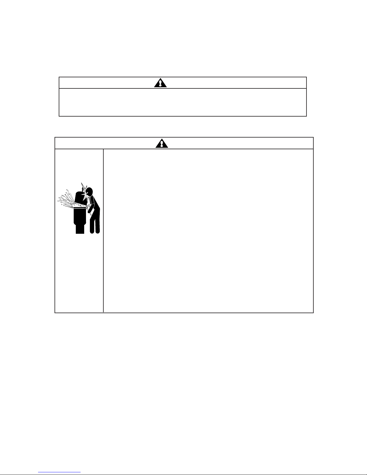
WARNING
Failure to operate your filter system or inadequate filtration can cause poor water clarity obstructing
visibility in your pool. Poor water clarity may obscure objects in the water which while swimming and
diving could cause severe personal injury and death. Never swim in a pool with poor water clarity.
SECTION III. CHECK VALVE INSTALLATION INSTRUCTIONS
WARNING
THIS FILTER OPERATES UNDER HIGH PRESSURE. WHEN ANY PART OF THE
CIRCULATING SYSTEM (e.g., LOCK RING, PUMP, FILTER, VALVES, ETC.) IS
SERVICED, AIR CAN ENTER THE SYSTEM AND BECOME PRESSURIZED.
PRESSURIZED AIR CAN CAUSE THE LID TO BE BLOWN OFF WHICH CAN RESULT IN
SEVERE INJURY, DEATH, OR PROPERTY DAMAGE. TO AVOID THIS POTENTIAL
HAZARD, FOLLOW THESE INSTRUCTIONS.
1. BEFORE REPOSITIONING VALVES AND BEFORE BEGINNING THE ASSEMBLY,
DISASSEMBLY, OR ADJUSTMENT OF THE LOCK RING OR ANY OTHER SERVICE
OF THE CIRCULATING SYSTEM: (A) TURN THE PUMP OFF AND SHUT OFF ANY
AUTOMATIC CONTROLS TO ENSURE THE SYSTEM IS NOT INADVERTENTLY
STARTED DURING THE SERVICING; (B) OPEN AIR RELIEF VALVE; (C) WAIT
UNTIL ALL PRESSURE IS RELIEVED.
2. WHENEVER INSTALLING THE FILTER LOCK RING FOLLOW THE CLEANING
FILTER INSTRUCTIONS EXACTLY.
3. ONCE SERVICE ON THE CIRCULATING SYSTEM IS COMPLETE FOLLOW INITIAL
START SYSTEM RESTART INSTRUCTIONS EXACTLY.
4. MAINTAIN CIRCULATION SYSTEM PROPERLY. REPLACE WORN OR DAMAGED
PARTS IMMEDIATELY (e.g., lock ring, pressure gauge, relief valve, O-rings, etc.).
5. BE SURE THAT THE FILTER IS PROPERLY MOUNTED AND POSITIONED
ACCORDING TO INSTRUCTIONS PROVIDED.
A. INSTALLATION
1. Turn the pump off, shut off any automatic controls to assure that the system is not inadvertently
started during servicing.
2 . Open the High Flow™ manual air relief valve.
3 . Plug the suction line by inserting a rag into the skimmer port, or if equipped with a valve close it at
this time to prevent water from siphoning from the pool during servicing.
4. If possible, plug the return line to prevent siphoning. If this can not be done, disconnect the union
fitting from the outlet port of the filter and quickly place the return hose into the pool.
5 . Remove the drain cap to empty the water from the filter.
REV. F 5-1-01 3 P/N 99101100
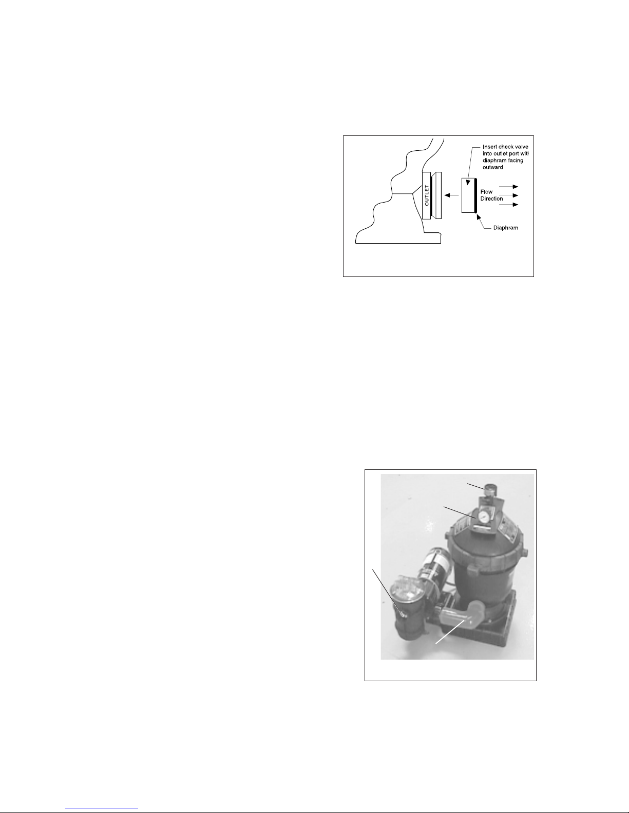
6 . Insert the Check Valve into the outlet port
approximately 3/4" to 1" deep making sure the
rubber diaphragm facing outward (towards you),
see Diagram 1.
7. Reconnect the return hose to the outlet port and
tighten the union fitting.
8 . Replace the drain cap.
9 . Remove the rag from the skimmer or open the
valve on the suction line.
10 . If the return line was plugged, unplug it at this time.
Diagram 1.
11 . With the High Flow™ manual air relief valve in the
open position, start the filter pump, after a steady stream of water appears close the High Flow™
manual air relief valve.
12. Your system is now in operating order.
SECTION IV. INSTALLATION
To install this filter system, you will need the following simple tools - a screwdriver, pliers, and wrench.
1 . Carefully remove the equipment from the carton and check for any evidence of damage due to
rough handling or shipping. If any of the equipment is damaged, immediately notify the
organization where the equipment was purchased.
2. Position a tee-nut on the boss underneath the skid base. Screw a bolt with washer into the tee-nut
from the top of the base. Continue screwing the bolt into the tee-nut until the tee-nut is flush with
the boss. Unscrew the bolt. Repeat procedure for the remaining bosses.
3 . This filter should be mounted on a level concrete slab, preferably concrete poured in a form or on
a platform constructed of concrete block or brick.
4 . Depending upon how your skimmer is positioned in
relationship to the return fitting, see Diagram 3, either
right or left of the skimmer, position the mounting base
Detail D
Detail C
accordingly; see Diagram 3. Position the filter tank on
the mounting base so the filter inlet port is oriented
toward the pump similar to Diagram 2. Secure the filter
to the mounting base using two bolt fasteners. Place
Detail B
the pump on the mounting base; see Diagram 2.
Loosely attach the pump connector, see Detail A, to the
pump and filter. This will align the pump to the correct
inlet
set of mounting holes. Secure the pump to the base
using two bolt fasteners. Tighten the union fittings on
the plumbing connector by hand until tight. If water
leakage occurs at these connections, adjust
Detail A
connections with a wrench making sure not to exceed 1/
4 of a turn.
P/N 99101100 4 REV. F 5-1-01
Diagram 2.
5 . Do not mount electrical controls (on/off switches, timer, etc.) over the filter. You need to be able to
stand clear of the filter when starting the pump.
6. Attach the hair and lint pot to the front of the pump. This is an O-ring seal fitting that requires hand
tightening only. (OVER TIGHTENING CAN RESULT IN DAMAGE TO THE O-RING SEAL)
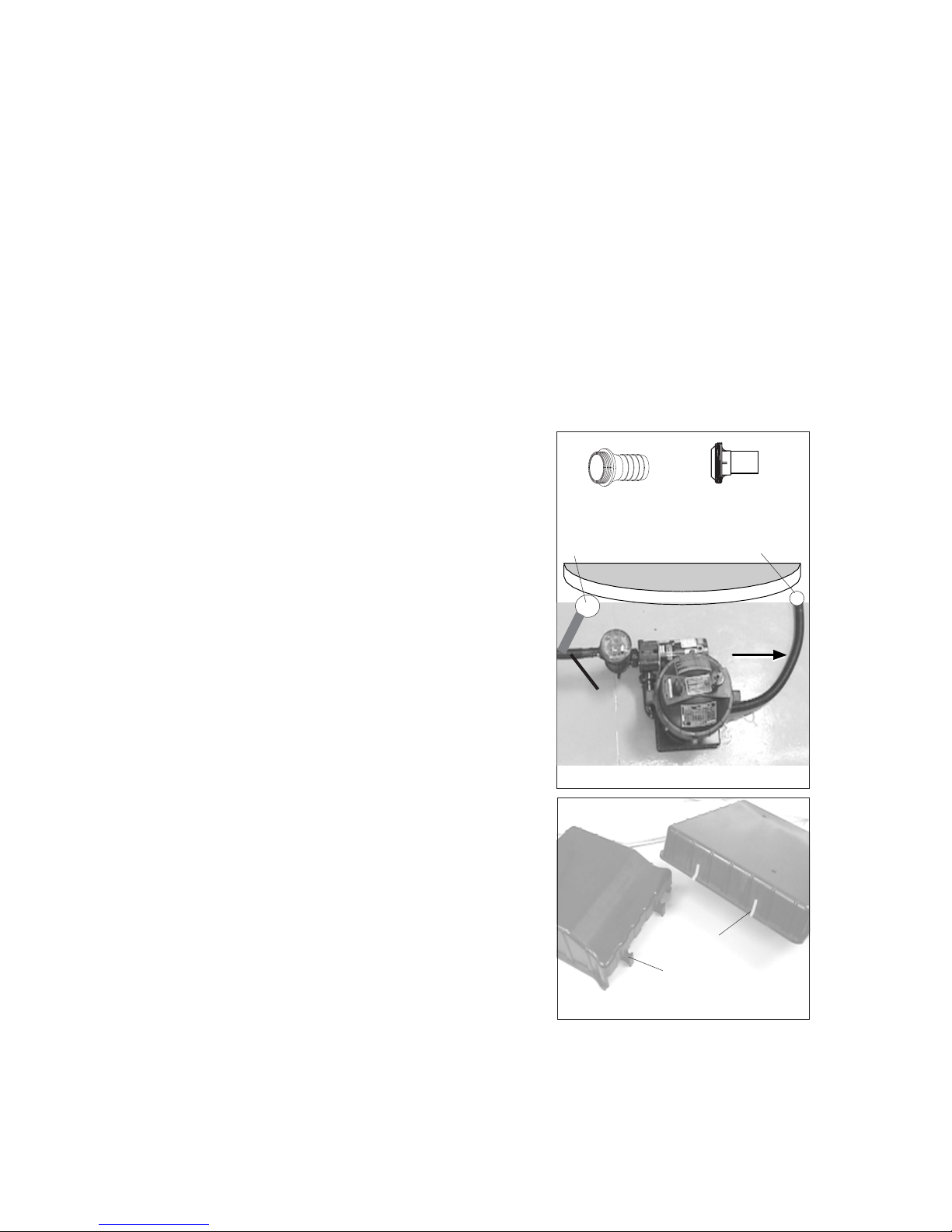
7 . Install the threaded fitting, see Diagram 3 – Figure 1, into the suction port of the pump. This is an
O-ring seal fitting that requires hand tightening only. (OVER TIGHTENING CAN RESULT IN
DAMAGE TO THE O-RING SEAL)
8. Install the threaded return fitting into the filter outlet port, see Diagram 3 – Figure 2, making sure that
the O-ring is in place in the filter body. Tighten this connection by hand until tight. If water leakage
occurs at this connection after installation, adjust connection with a wrench making sure not to exceed
1/4 of a turn. (OVER TIGHTENING CAN RESULT IN DAMAGE TO THE FILTER)
9. Connect black hoses to the equipment and the pool with
the clamps provided.
a. Connect the skimmer suction port from the pool to
the pump inlet.
b. Connect the filter outlet port to the return fitting of
the pool, see Figure 1.
c. Install the High Flow™ air relief valve, see Diagram
2 – Detail C, into the top of the filter tank lid. This is
an O-ring seal that requires hand tightening only.
d. Install the pressure gauge, see Diagram 2 – Detail D,
using the Teflon tape provided. Wrap the threads of
the pressure gauge with three layers. Install the
gauge into the top of the filter tank until tight.
10. Never install a pump in this system that exceeds the
maximum pressure of this filter,
see data label.
11. If using the optional Chlorinator Base, knockout the
two slots on the system base with a hammer and
screwdriver.
12. Slide the two tabs on the Chlorinator Base into the slots
on the system base; see Diagram 4.
Figure 1.
Skimmer
To
Skimmer
Figure 2.
Return
POOL
To
Return
Fitting
Diagram 3.
Slots
REV. F 5-1-01 5 P/N 99101100
Tabs
Diagram 4.
 Loading...