

Pentair 9302C-HM2C, 9302C-HMIC, 9303C-HMIC, 9302CT-GM1, 9302C-HM4C Installation, Operation, Repair And Parts Manual
...
Series 9300 Hydraulically-Driven
Centrifugal Pumps
Installation, Operation, Repair and Parts Manual
Description
Form L-1526
(12/12, Rev. B)
Hypro centrifugal pumps are designed for agricultural and
industrial spraying and transfer of a variety of fluids: water,
insecticides, herbicides, wettable powders, emulsives, liquid
fertilizers, etc. Polypropylene centrifugal pumps may also be
used to pump acid fertilizer, calcium chloride and other highly
corrosive liquids such as sulfuric and phosphoric acids.
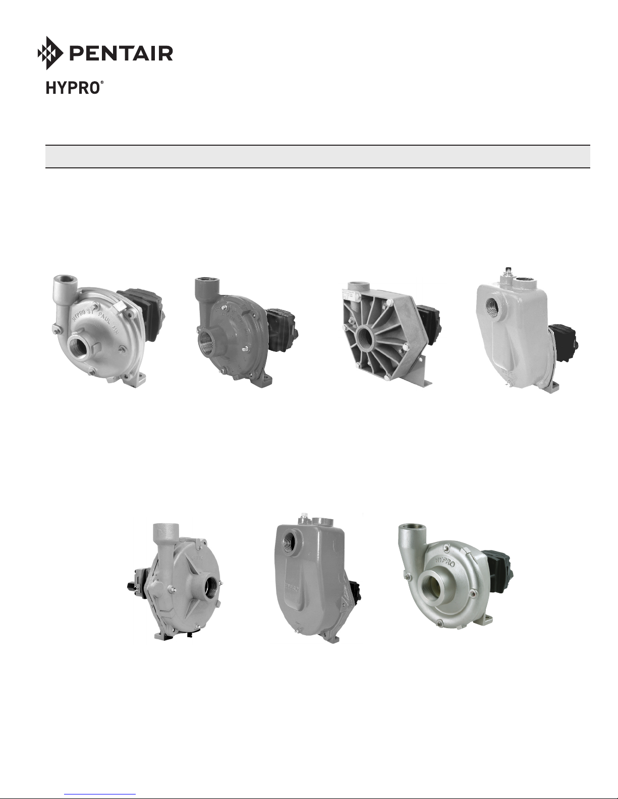
SERIES 9302C & 9302S
Cast Iron & Stainless Steel
Centrifugal Pumps
Max. Flow Rate: .............. 100 gpm
Max. Pressure: ...................120 psi
Ports: ....................1-1/4” NPT Inlet
.................................. 1” NPT Outlet
Hydraulic Ports: ...... 1/2” NPT Inlet
.................................3/4” NPT Tank
SERIES 9303C & 9303S
Cast Iron & Stainless Steel
Centrifugal Pumps
Max. Flow Rate: .............. 147 gpm
Max. Pressure: ...................145 psi
Ports: ....................1-1/2” NPT Inlet
............................ 1-1/4” NPT Outlet
Hydraulic Ports: ...... 1/2” NPT Inlet
.................................3/4” NPT Tank
Hypro Series 9300 hydraulic motor-driven centrifugal pumps
provide smooth performance. They can be conveniently
mounted on the tractor or sprayer, becoming part of the vehicle’s hydraulic system and freeing the PTO for other uses.
The Hypro “close-coupled” design reduces the mounting
space required, eliminating long shafts and couplers between the pump and motor.
SERIES 9303P
Polypropylene
Centrifugal Pumps
Max. Flow Rate: .............. 113 gpm
Max. Pressure: ...................125 psi
Ports: ....................1-1/2” NPT Inlet
............................ 1-1/4” NPT Outlet
Hydraulic Ports: ..... 1/2” NPT Inlet
.................................3/4” NPT Tank
SERIES 9303C-SP
Cast Iron Centrifugal Pumps
Max. Flow Rate: .............. 122 gpm
Max. Pressure: ...................140 psi
Ports: ....................1-1/2” NPT Inlet
............................ 1-1/4” NPT Outlet
Hydraulic Ports: ...... 1/2” NPT Inlet
.................................3/4” NPT Tank
SERIES 9305C-HM3C
Cast Iron Centrifugal Pumps
Max. Flow Rate: .............. 190 gpm
Max. Pressure: ...................180 psi
Ports: .......................... 2” NPT Inlet
............................ 1-1/2” NPT Outlet
Hydraulic Ports: ...... 1/2” NPT Inlet
.................................3/4” NPT Tank
SERIES 9305C-
HM3C-SP, -BSP
Cast Iron Centrifugal Pumps
Max. Flow Rate: .............. 178 gpm
Max. Pressure: ...................154 psi
Ports: ..............2” NPT or BSP Inlet
......................2” NPT or BSP Outlet
Hydraulic Ports: ...... 1/2” NPT Inlet
.................................3/4” NPT Tank
SERIES 9306C & 9306S
Cast Iron & Stainless Steel
Centrifugal Pumps
Max. Flow Rate: .............. 214 gpm
Max. Pressure: ...................150 psi
Ports: .......................... 2” NPT Inlet
............................ 1-1/2” NPT Outlet
Hydraulic Ports: ..... 1/2” NPT Inlet
.................................3/4” NPT Tank

General Safety Information
California Proposition 65 Warning -- This product
and related accessories contain chemicals known to the
State of California to cause cancer, birth defects or other
reproductive harm.
Notes are used to notify of installation, operation, or
maintenance information that is important but not safety
related.
Caution is used to indicate the presence of a hazard,
which will or may cause minor injury or property damage
if the notice is ignored.
Warning denotes that a potential hazard exists and
indicates procedures that must be followed exactly to
either eliminate or reduce the hazard, and to avoid serious
personal injury, or prevent future safety problems with
the product.
Danger is used to indicate the presence of a hazard
that will result in severe personal injury, death, or
property damage if the notice is ignored.
Do not pump flammable or explosive fluids such as
gasoline, fuel oil, kerosene, etc. Do not use in explosive
atmospheres. Components not rated for use with
Anhydrous Ammonia. The pump should be used only
with liquids compatible with the pump component
materials. Failure to follow this notice may result in
severe personal injury and/or property damage and will
void the product warranty.
1. Do not pump at pressures higher than the maximum
recommended pressure.
o
2. Maximum liquid temperature is 140
centrifugal pumps.
3. Disconnect power before servicing.
4. Release all pressure within the system before
servicing any component.
5. Drain all liquids from the system before servicing
any component. Flush with water.
6. Secure the outlet lines before starting the pump. An
unsecured line may whip, causing personal injury
and/or property damage.
7. Check hose for weak or worn condition before each
use. Make certain that all connections are tightly
secured.
8. Periodically inspect the pump and the system
components. Perform routine maintenance as
required (See Repair Instructions).
9. Use only pipe, hose and fittings rated for the
maximum psi rating of the pump.
10. Do not use these pumps for pumping water or other
liquids for human or animal consumption.
F for Series 9300
Hazardous Substance Alert
1. Always drain and flush pump before servicing or disassembling for any reason.
2. Always drain and flush pumps prior to returning unit
for repair.
3. Never store pumps containing hazardous chemicals.
4. Before returning pump for service/repair, drain out
all liquids and flush unit with neutralizing liquid.
Then, drain the pump. Attach tag or include written
notice certifying that this has been done. It is illegal
to ship or transport any hazardous chemicals without United States Environmental Protection Agency
Licensing.
L-1526 (12/12, Rev. B)
Never use your hand to check the condition of hydraulic
lines or hoses. If hydraulic fluid penetrates the skin, get
medical help immediately. Failure to get proper medical
help may result in loss of limb or life. The safest way to
check hydraulic lines or hoses is by holding a piece of
cardboard next to the hydraulic line or hose.
The sound pressure level of the pump is 80dBA. Observe
all safety precautions when operating the pump within
close proximity for extended periods of time by wearing hearing protectors. Extended exposure to elevated
sound levels will result in permanent loss of hearing
acuteness, tinnitus, tiredness, stress, and other effects
such as loss of balance and awareness.
-2-
Hydraulic Pumps
General Information—Hydraulic Systems
Hydraulic pumps come in two basic types:
• Constant displacement - which will continue to put
out its rated flow regardless of pressure, until the relief valve bypasses the flow.
• Variable displacement - which will produce only the
flow needed by the implement until the total pump
output is reached. If less than the full pump output
is required, an automatic stroke control mechanism
decreases the pump output to maintain a constant
pressure and flow. The output varies according to
demand.
Open Center
Spool Valve
In Neutral
Position
Figure 1
Spool Valves
There are two basic types of spool valves used in conjunction
with these pumps — Open and Closed Center. In the Open
Center Valve (See Figure 1), the flow goes straight through
the valve when in the neutral position. This type is used for
constant displacement pumps where the flow should never
be shut off.
Closed Center
Spool Valve
In Neutral
Position
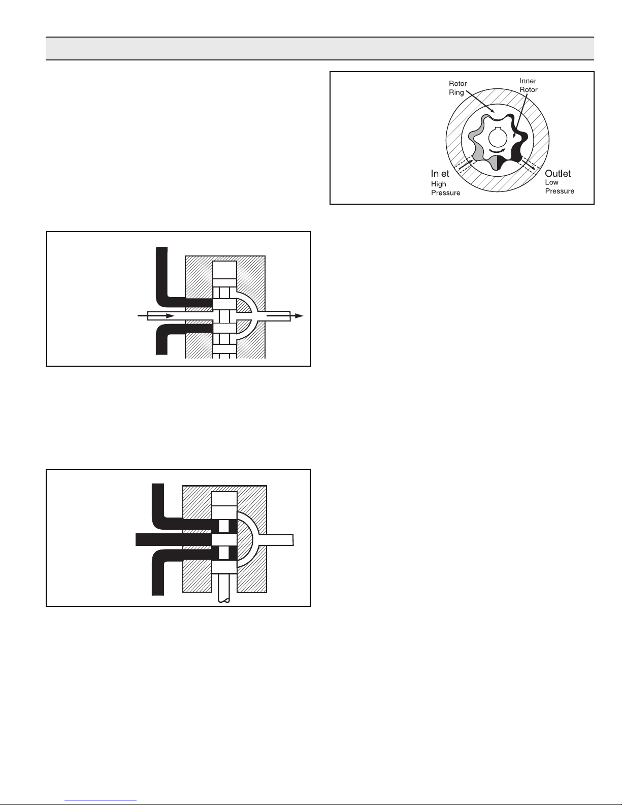
Gerotor-Type
Hydraulic Motor
Figure 3
Three Systems
Fitting these components together and installing a motor,
we have one of the three types of systems: Open Center,
Closed Center (pressure compensated) and Closed Center
Load Sensing (flow and pressure compensated).
Open Center Systems
In an Open Center System, the hydraulic pump puts out a
constant flow. If the pump puts out more oil than the motor can use, a portion of the oil must be bypassed around
the motor. When the oil is bypassed around a loop and does
no work, the energy put into it by the pump turns into heat.
Therefore, the amount of oil bypassed should be kept to a
minimum. Use the largest motor possible.
Closed Center (Pressure-Compensated) Systems
The Closed Center Pressure-Compensated system has a
variable displacement pump which will deliver flow at the
necessary rate to maintain a specified pressure. It is desirable to equip implements with a motor of a low flow range
that will cause the pump to operate between 1800 and 2100
psi [124 and 145 BAR]. A motor that requires a large volume to obtain the correct implement speed usually causes
the hydraulic pump in a closed center system to operate at
a lower pressure than desirable. This low pressure results in
unnecessary flow and the generation of heat that lowers the
lubricating quality of the oil and may damage transmission
parts. Use the smallest motor possible.
Figure 2
The Closed Center Valve (See Figure 2) is used with variable
displacement pumps. The flow is completely shut off in the
neutral position, causing the pump stroke to adjust to zero
flow. The flow stops, but the pump maintains a static pressure up to the valve.
Hydraulic Motors
Figure 3 shows an internal gear motor (Gerotor) where pressure causes the cavities between the gears to expand on one
side, developing torque. The Gerotor type of hydraulic motor
is used on Hypro pumps for its superior performance characteristics, including cooler running and higher rpm capabilities.
Closed Center Load Sensing Systems
(Flow and Pressure-Compensating)
The Closed Center Flow-Compensated System is a variation
of the pressure-compensated system, designed primarily for
more efficient operation and the generation of less heat. It
works on the principle of maintaining a constant pressure
drop from the pump to the work port of the selector valve. Any
variation in demand at the motor will cause a change in flow.
The system senses this change in flow due to the change
in pressure drop across the valve and causes the pump to
compensate by varying the pump flow. No restrictor is used
in the pressure line and no oil is bypassed.
-3-
L-1526 (12/12, Rev. B)
Plumbing Installation
7
6
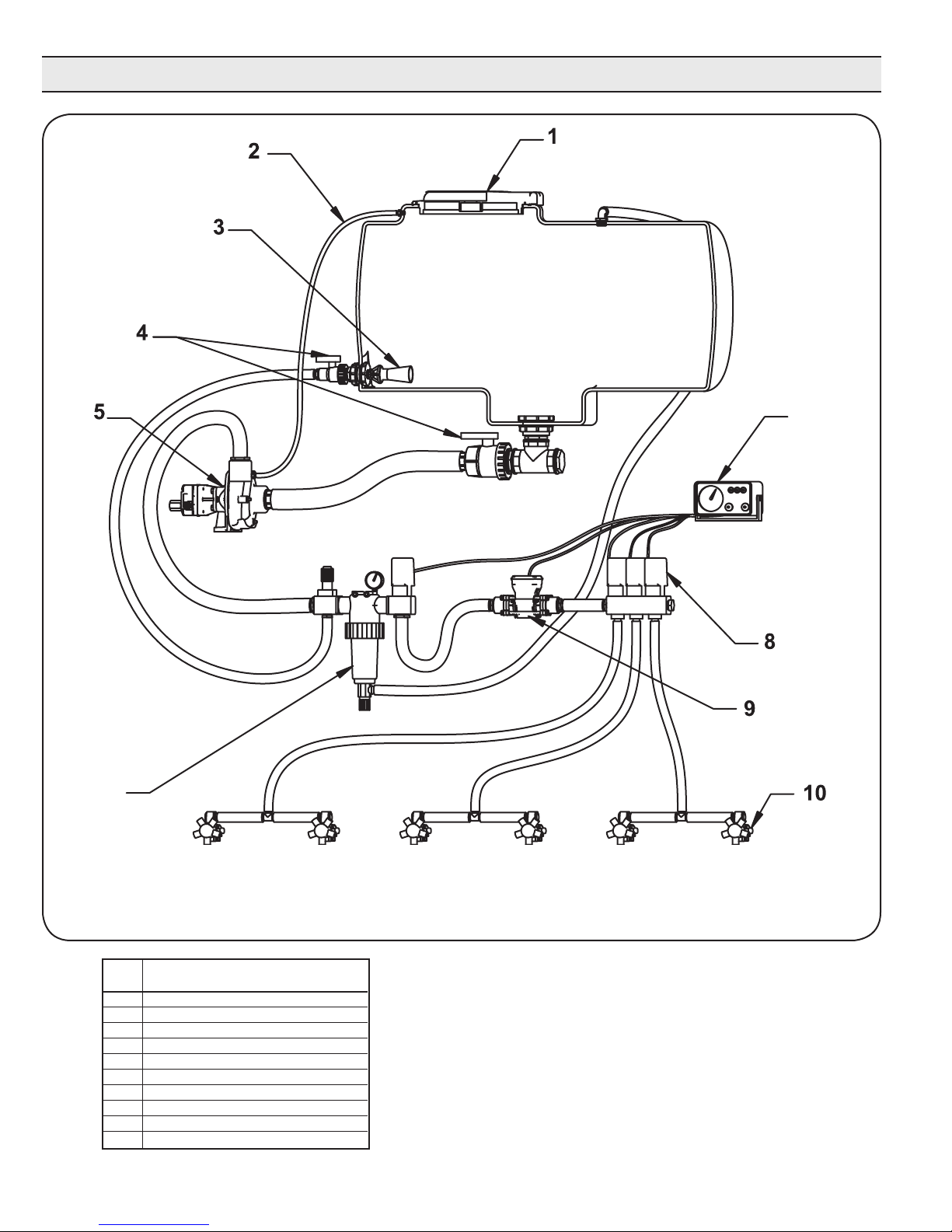
Centrifugal Plumbing Hook-up
REF. DESCRIPTION
NO.
1 Tank Lid
2 Vent Line #3430-0456
3 Jet Agitator
4 Shut-off Ball Valves
5 Centrifugal Pump
6 Spray Control Console
7 Centrifugal Pump Control
8 Manifold Boom Valve
9 Electromagnetic Flowmeter
10 Compact Jet Turret Nozzle Body
L-1526 (12/12, Rev. B)
-4-

Installation Instructions
All Models — Open Center Systems
Models include Tank Port Adapter with built-in Check Valve
Assembly and Pressure Port Adapter.
HM2C and HM4C Models Only — Closed Center and
Small Open Center Systems.
Models include Tank Port Adapter with built-in Check Valve
Assembly and Pressure Port Adapter with three different
size metering orifices for HM4C models. The orifices are not
required for use with closed center systems with flow control,
such as John Deere closed center systems. Also, do not
use for small open center systems with a maximum flow of
8 gpm [30.28 lpm] for HM2C model; 10 gpm [37.85 lpm] for
HM4C model. If necessary, the pressure port adapter may be
used without a metering orifice installed in any closed center
system. For best results, the pressure differential across the
motor should be less than 2500 psi (170 bar).
Preliminary to Mounting
Consult the owners manual to determine the type and
capacity of the hydraulic system. Make sure the hydraulic
system is recommended to operate with a continuous load.
Refer to the Pump Selection Guide to confirm you have the
proper pump for your hydraulic system.
Check to see that the pump impeller can be turned by hand.
(Turn the shaft clockwise using a deep socket wrench on the
impeller nut.) If it cannot be turned, open the pump casing to
look for obstructions. Clean out any corrosion build up where
the casing fits over the eye of the impeller.
Pump Inlet Line
To achieve full capacity from the pump, the inlet line should
be at least the same size as the inlet port on the pump.
Reducing this line size will restrict the capabilities of the
pump. The line must also be free of air leaks. Check all
fittings and connections in the suction line for tightness.
The introduction of air may affect the priming and pumping
capabilities of the pump. Use good quality suction hose that
will not be collapsed by suction.
For non self-priming models, the centrifugal pump should
be mounted below the liquid level and as near to the liquid
source as possible to allow for the shortest suction line
practical. To achieve optimal performance, the suction line
should slope down into the pump. Avoid rises and humps
that could trap air in the line to the pump. The suction line
and pump should be filled with liquid prior to starting the
pump, and all discharge lines should be open.
Pump Outlet Line
The recommended orientation for the outlet port is pointing
straight up. This allows liquid to stay in the pump while it
is priming. The outlet line should be the same size as the
pressure port on the pump to give the optimal flow. The line
should have as few restrictions and elbows as possible to
optimize the pump performance and reduce pressure drop
from the pump to the spray tips.
Priming the Pump
The pump must not be run dry.
Before starting the pump, the inlet line and pump must be
filled with liquid and all discharge lines must be open. On selfpriming models, only the pump chamber needs to be filled
with liquid. The pump must not be run unless it is completely
filled with liquid because there is a danger of damaging
the mechanical seal, which depends on the liquid for its
lubrication.
Non-self-priming models should be mounted below the level
of the liquid. The suction line should slope down to the pump
and be free of dips and bends. If this cannot be done, a foot
valve should be installed in the end of the inlet line so that
the line can be completely filled with liquid before starting the
pump.
For best priming results, the top vent plug should be
removed from the pump casing. A vent line (1/4” [6.35
mm] tubing is sufficient) should be installed running
back to the top of the tank. This line prevents air lock and
allows the pump to prime itself by bleeding off trapped air. The
small stream of liquid that returns to the tank during operation
is negligible. The discharge from this line should be positioned
in the tank above the high liquid level. Self-priming models
can be primed by removing the top vent plug and filling the
priming chamber. The priming chamber will fill to the level
of the inlet port. After use, the priming chamber should be
flushed and drained to avoid chemical corrosion and damage
from freezing. Drain by removing the lower drain plug.
Controlling the Pump Flow
The best way to control the flow is by incorporating two
control valves in a pipe tee immediately after the strainer
in the discharge line. This permits controlling agitation flow
independently of nozzle flow.
In any centrifugal pump, it is the large volume of liquid which
puts load on the drive. Use only the flow needed to develop
the pressure required at the boom and to maintain adequate
agitation. Hydraulic motor-driven centrifugal pumps are
easily adjusted to the exact flow required, as explained in the
Operating Instructions of this manual.
Centrifugal Pump Control
Hypro now offers many different components for spraying
systems. The Hypro centrifugal pump control incorporates
the electric flow control valve, a self-cleaning line strainer, a
visual pressure gauge and a manual agitation control valve.
Flow Control Valve
A high-flow electric proportional valve allows for maximum
flow control to the boom valves. It provides smooth, rapid
control that can be controlled from either an electronic rate
controller or switch box.
Strainers
The recommended placement of the strainer for a centrifugal
pump is in the pump outlet line. This will eliminate any
possible restriction that the strainer could create if it were
installed in the inlet line. Ensure that the proper strainer
size and screen mesh are used to limit the pressure drop
-5-
L-1526 (12/12, Rev. B)

Plumbing Installation
and achieve the best filtration. Line strainers can also be
installed in the tank fill line to filter liquid as it is loaded into
the tank as well as in the boom lines to further filter the
solution prior to the spray tips. Tank baskets can also be
used to filter material added through the tank lid.
Agitation
The centrifugal pump control contains a manual agitation
control valve that can be adjusted to provide the right
amount of flow to the jet agitators in the tank to ensure
proper mixing within the tank.
Flowmeter
To eliminate the mechanical problems of a turbine flowmeter,
we recommend that an electromagnetic flowmeter be used.
These flowmeters have no moving parts to wear out and will
provide a more consistent and accurate flow reading. They
can be input into just about any electronic rate controller or
switch box.
Boom Section Valves
For rapid response and reliability, we recommend electric
plunger valves be used for boom control. The valves should
be sized accordingly to minimize the pressure drop and
maximize the flow rate. The boom tubing or hose should
be sized accordingly to ensure that a pressure drop in the
lines does not occur, causing inconsistent pressures at the
nozzles.
Nozzle Bodies
Nozzle bodies with shut-off check valves are recommended
to eliminate dripping from the spray tips when the boom
valves are shut down.
Hooking Up the Hydraulic Motor to the
Tractor Hydraulic System
Hypro Series 9300HMC hydraulic motor-driven pumps can
be mounted on either the tractor or sprayer. When hooking
up, make sure that no dirt or liquid gets into the hydraulic
motor. Keep all hydraulic connections clean. Be sure
to connect the hydraulic motor into the system correctly by
putting the pressure line to the Pressure Port Adapter and
return line to the Tank Port Adapter. The adapters on the
hydraulic motor are sized to accommodate 1/2” NPT fittings
on the pressure port and 3/4” NPT on the tank port. For
maximum performance, the hydraulic lines should also be at
least 1/2” [12.7 mm] in size for the pressure line and 3/4”
[19.05 mm] for the tank line.
The tank (OUT) port adapter with a built-in check valve
assembly will guard against reverse operation — allowing you
to reverse oil flow to operate other equipment. This adapter
must not be removed. On HM2C and HM4C model pumps,
the pressure (IN) port adapter is a two-piece assembly
consisting of an open (unrestricted) adapter with three orifices
packed loose with the pump. (See the Operations Section.)
When using the HM2C or HM4C unit on any flow- compensated
(load sensing) closed center system, or any small open center
system with a maximum flow of 8 gpm [30.28 lpm] for HM2C
or 10 gpm [37.85 lpm] for HM4C, the metering orifice should
be removed from the pressure port adapter. When using these
units on flow-compensated systems, connect to the motor
priority circuit if your tractor has one.
Standard spool valves, which are found on all tractor
hydraulic systems, may cause potentially damaging high
peak pressures in the hydraulic system when closed because
of abrupt shut-off of oil flow in both the supply and return
lines. When shutting off the pump, move the selector to the
FLOAT position to allow the centrifugal pump to come to a
stop gradually.
For further information
regarding Hypro products,
contact your local dealer or
Hypro directly at
www.hypropumps.com or by
calling 1-800-424-9776.
Open Center Systems— All Models
Adjusting Centrifugal Pump Output
HM1C, HM3C & HM5C motors have bypass screw fully
closed from the factory. HM2C & HM4C motors have bypass
screw set at 1-1/2 turns from fully closed from the factory.
1. Open the bypass adjustment screw 2-1/2 turns from fully
closed. Turn the bypass screw in to achieve the flow for
the desired gpm and psi.
2. Start the tractor. Leave the directional valve in the
neutral position and allow hydraulic oil to circulate for
approximately 10 to 15 minutes or until adequately
warmed.
L-1526 (12/12, Rev. B)
Operation
3. Prime the centrifugal pump with all valves open (See
the Installation Instructions and System Configuration
Diagram).
4. Close the agitation line valve and keep the control
valve and the boom shut-off valve open. Note the spray
pressure.
5. Open the agitation line valve until you have desired
circulation in the tank. Recheck the spray pressure. If it
is too low, close down the agitation line valve until the
desired spray pressure is reached. If the spray pressure
is too high, throttle the centrifugal pump by closing down
the control valve.
-6-

Closed Center (Pressure-Compensated) —
HM2C and HM4C Models Only
On a pressure-compensated system, the amount of oil that
is allowed to flow through the hydraulic motor is regulated
by a metering orifice in the pressure port adapter. Three
different sizes of orifices are supplied with the HM2C and
HM4C model pumps to allow flexibility in the flow required for
individual sprayer needs.
The smaller the orifice, the less hydraulic oil goes through
the motor, so the pump will run slower and the flow of liquid
pumped and the spray pressure will also be less. As the
hydraulic oil flow is increased (by installing a larger orifice),
the amount of liquid being pumped and the spray pressure is
also increased.
Installing and Removing Metering Orifice
1. Shut off the hydraulic system.
2. Disconnect the line to the pressure port of the hydraulic
motor.
3. Remove the adapter from the motor using a 1-1/16’’
wrench. Make sure the o-ring is on the metering orifice
before installing into port adapter.
4. The orifice is removed or installed in the port adapter by
tapping either in or out of the adapter.
A. To remove — tap the orifice out from the small end
of the adapter.
B. To install — tap the orifice in from the large end of
the adapter. The orifice is seated when a snap sound
is heard.
Adjusting Centrifugal Pump Output
1. Open the bypass adjusting screw in the hydraulic motor
three (3) turns.
2. Start the tractor and allow the hydraulic oil to circulate
for approximately 10 to 15 minutes or until adequately
warmed.
3. Close and lock down the bypass adjusting screw in the
hydraulic motor.
4. Prime the centrifugal pump with all valves open (See
Installation Instructions and System Configuration
Diagram).
5. Close the agitation line valve and the control valve; open
the boom shut-off valve.
6. With the pump running, open the control valve until the
pressure gauge indicates the desired spraying pressure.
7. Open the agitation line valve until sufficient agitation is
observed. Then, if spray pressure drops, readjust the
control valve to restore to the desired pressure.
8. If a sufficient boom pressure cannot be attained, install
the #2 size orifice and repeat Steps 5 through 7.
9. If a sufficient boom pressure still cannot be attained with
the #2 size orifice, install the #3 size orifice and repeat
Steps 5 through 7.
10. If a sufficient boom pressure still cannot be attained
with the #3 size orifice, remove the orifice and repeat
Steps 5 through 7.
Closed Center (Load Sensing) — All Models
Many tractors are being introduced with load sensing
systems (also referred to as flow and pressure- compensated
systems) which simplify system setup and eliminate many
of the problems associated with using the wrong size pump
motors on a given hydraulic system. Usually, any of Hypro’s
9300HMC models may be used on this type of system,
provided the hydraulic system produces sufficient oil flow for
the hydraulic motor being used (Refer to the Pump Selection
Guide).
This system maintains a constant flow of hydraulic oil for a
given pressure drop. The flow is adjustable with a flow control
valve installed in the hydraulic system (such as the Tortoise/
Hare control on John Deere tractors). Because this system
has adjustable flow, there is no need to bypass hydraulic oil
as in an open center system, or to restrict the flow with orifices
as in a closed center pressure- compensated system.
Adjusting Centrifugal Pump Output
1. Make sure the orifice from the pressure port adapter
of the hydraulic motor has been removed (HM2C and
HM4C models only).
2. Close and lock down the bypass adjusting screw in the
hydraulic motor.
3. Set the tractor hydraulic flow control valve for minimum
hydraulic oil flow to the remote outlet (Tortoise position).
4. Start the tractor and allow the hydraulic oil to circulate
for approximately 10 to 15 minutes or until adequately
warmed.
5. Prime the centrifugal pump with all valves open (See
the Installation Instructions and System Configuration
Diagram).
6. Close the agitation line valve and open the control valve
and the boom shut-off valve.
7. Slowly adjust the tractor hydraulic flow control valve until
the desired boom pressure is attained.
8. Open the agitation line valve until sufficient agitation is
observed. If spray pressure drops, readjust the tractor
hydraulic flow control valve to restore it to the desired
pressure.
Flush Pump After Use
One of the most common causes for faulty pump performance
is gumming or corrosion inside the pump. Flush the pump
and entire system with a solution that will chemically
neutralize the liquid pumped. Mix this solution according to
the manufacturer’s directions. This will dissolve most residue
remaining in the pump, leaving the inside of the pump clean
for the next use.
To Prevent Corrosion
After cleaning the pump as directed above, flush it with a
permanent-type automobile antifreeze (Prestone®, Zerex®,
etc.) containing a rust inhibitor. Use a 50% solution, half
antifreeze and half water. A protective coating will remain on
the inner pump surfaces. Save the excess antifreeze for the
next application. Plug the ports to keep out air during storage.
For short periods of idleness, noncorrosive liquids may be left
in the pump, but air must be kept out. Plug the ports or the
seal port connections.
-7-
L-1526 (12/12, Rev. B)
Repair Instructions
Hypro Repair Tools:
ToolBoxNo.3010-0168•1/4”AllenWrenchNo.3020-0008
SupportBars(2)No.3010-0064•PortBrushNo.3010-0066
1/16”AllenWrenchNo.3020-0009•BrushHolderNo.3010-0067•
LargeRetainingRingPliersNo. 3010-0084 • Small RetainingRing
Pliers No. 3010-0167
NOTE:
Shop Tools Needed:
BenchVice•ArborPress•AirorHandDrill•SmallKnife
Metal Pipe - 1” dia. x 4” high (Bearing Seating Tool)
PVC Pipe - 3/4” dia. x 4” - 6” high (Seal Seating Tool)
12”CrescentWrench•TwoFlatScrewdrivers(approx.10”long)
1/2’’,9/16”,5/8”and7/8”sockets•HammerorRubberMallet
SmallScrewdriver(recommended)•LargeFile(optional)
1/2”and9/16”BoxEndWrench•LubricatingSpray(WD-40orLPS)
SmallamountHydraulicOil•CleaningSolventTank(recommended)
Pump Housing Disassembly
Instructions in italics describe procedures for the Series
9300P Polypropylene Centrifugal Pumps, when different
than the cast iron pumps.
1. Using a 9/16” box end wrench, remove the four Hex
Head Bolts holding the Pump Casing to the Mounting
Flange. (If necessary, tap Pump Casing Outlet Port with
rubber mallet or hammer to separate.) [Using a 1/2”
wrench, remove the six bolts from the front. For the two
bottom bolts securing the base, you will need to hold the
two nuts with another 1/2” wrench. Also remove the 5/16”
screw from the rear, near the outlet port.]
Visit our website at
www.hypropumps.com
for video repair procedures,
under the Tools section.
3. Once nut [and washer] is removed, place a screwdriver
on each side behind the Impeller and pry away from
the Mounting Flange (See Figure 7). Remove Woodruff
KeyfromtheShaft.RemoveO-ringfromthe Mounting
Flange.
Pump Seal Removal
1. Lightly lubricate the Shaft for easier removal of the Seal.
Using two screwdrivers positioned opposite each other,
pry the rotary portion of the Seal from the Shaft (See
Figure 8).
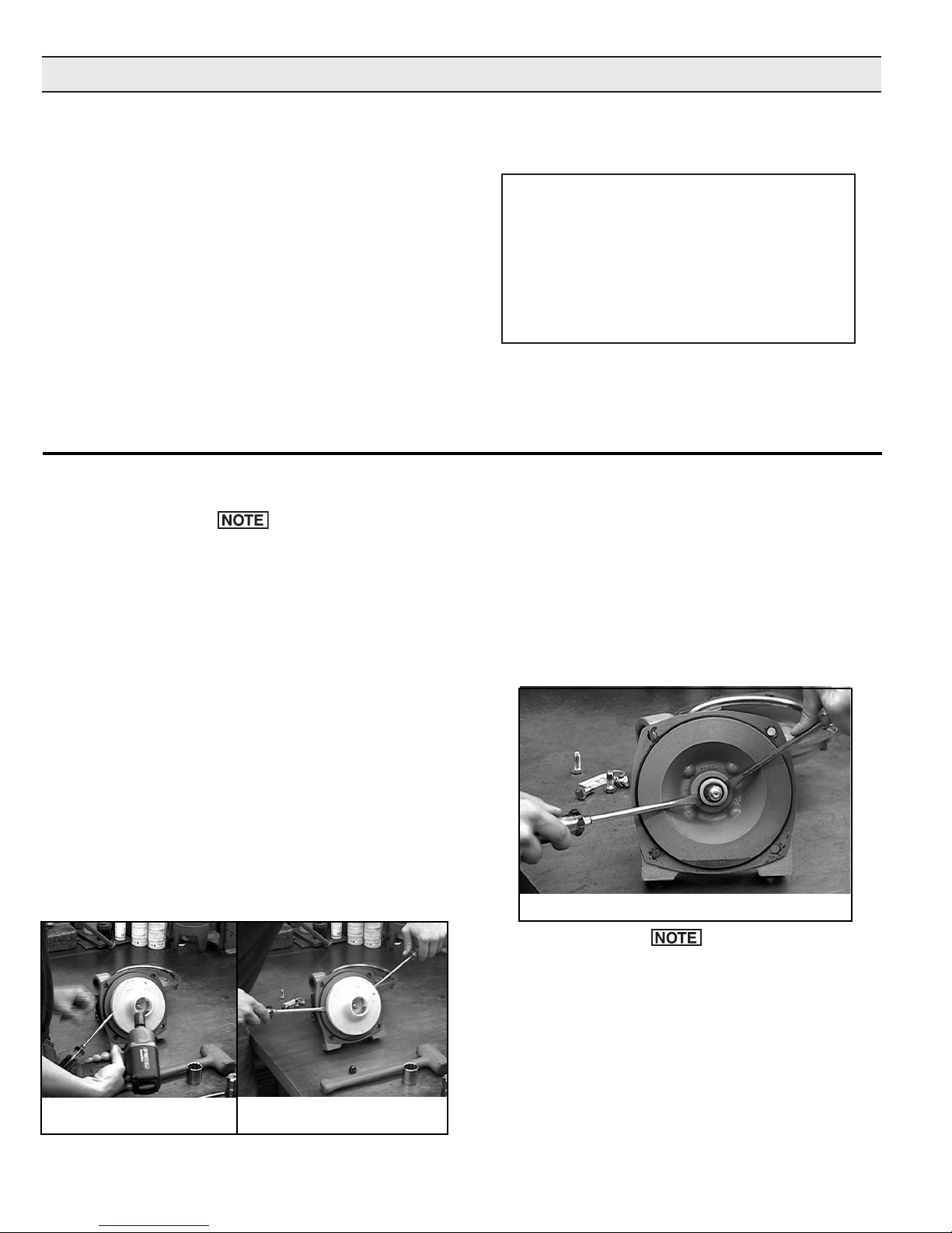
2. To remove the Impeller Nut, insert a large screwdriver
or file (at least 10” [254 mm] long) into Impeller Vanes to
prevent Impeller from turning when loosening nut. Use a
5/8” socket wrench to remove the Impeller Nut by turning
it counterclockwise (See Figure 6). [Use 7/8” deep
socket wrench to remove Plastic Seal Nut, then 9/16”
deep socket to remove Metal Jam Nut and Washer.]
Figure 6
L-1526 (12/12, Rev. B)
Figure 7
Figure 8
In the case of a severe pump seal leak, inspect the
Shaft/Bearing Assembly in the hydraulic motor for
possible contamination.
2. Using a 1/2’’ box end wrench, remove the four bolts
holding the Motor to the Mounting Flange. Remove
Motor. [Remove the Plastic Back Cover flange. Knock
the Seal out from back with a hammer and screwdriver.
Use a 1/2’’ socket wrench and 1/2’’ box end wrench to
remove the Mounting Flange from the Hydraulic Motor.]
-8-
3. Using a screwdriver and hammer, tap out the stationary
portion of the Mechanical Seal from the motor side of the
Mounting Flange. (If the motor is not removed, the seal
can be pried out with a small screwdriver.)
The seal will be damaged by removal in this manner. A
new seal must be used when pump is reassembled.
Clean-Up Of Pump Housing
1. Using a circular bottle-type wire brush with air or hand
drill, clean the Outlet Port, Inlet Port and the sealing
areas of the o-ring on the Pump Casing and Mounting
Flange. Using the port brush, clean the seal cavity in the
Mounting Flange. [The last step should not be performed
on the 9300P.]
2. After wire brush cleaning, it is recommended that the
Pump Casing and Mounting Flange be further cleaned in
a solvent tank to remove rust and corrosion particles.
The threads of the Plastic Seal Nut are fine and can
be easily cross threaded. To prevent cross threading,
turn the Plastic Seal Nut counterclockwise until area
of thread engagement is detected; then turn the Plastic
Seal Nut clockwise until it is secure. Do not over tighten
the Plastic Seal Nut.
6. InsertaWoodruffKeyintotheShaftkeyslot;thenplace
theImpellerontheShaftandalignitwiththeKey and
press against the Mechanical Seal Assembly. Apply a
blue thread locking compound to the Impeller Nut, and
using a 5/8’’ socket wrench and using a screwdriver to hold
the Impeller, install the Impeller Nut. [On polypropylene
models, insert the Woodruff Key into the Shaft key slot.
Place the Impeller on the Shaft and align it with the Key;
then press against the Mechanical Seal Assembly. Place
the Metal Seal Washer on the Shaft. Apply a drop of blue
thread locking compound on the Impeller Nut and secure
the Impeller to the Shaft as described previously.]
Seal Replacement/Pump Housing Reassembly
If the hydraulic motor requires repair, proceed to
Disassembly and Repair of the Hydraulic Motor in the
next column.
1. Lubricate the seal cavity in the Mounting Flange with
®
WD-40
, LPS or equivalent. Do not lubricate the shaft.
2. Install the stationary portion of the Mechanical Seal by
sliding over the Shaft with the ceramic side out.
Make sure both the seal cavity and seal are clean and
lubricated.
3. To seat the seal in the seal cavity, use a piece of 3/4”
PVC pipe 4” to 6” [101.6 to 152.4 mm] in length. Lubricate
sealing surface on seal after it is seated. Do not lubricate
the shaft.
4. To install the rotary portion of the mechanical seal, place
it over the shaft with the carbon side facing in, and press
against the stationary portion (See Figure 9).
5. Install rubber gasket 1700-0100 over shaft against rotary
portion of seal.
7. Install the o-ring on the mounting flange. Replace the
o-ring if worn or damaged.
8. Place the pump casing on the mounting flange, insert
and tighten the bolts.
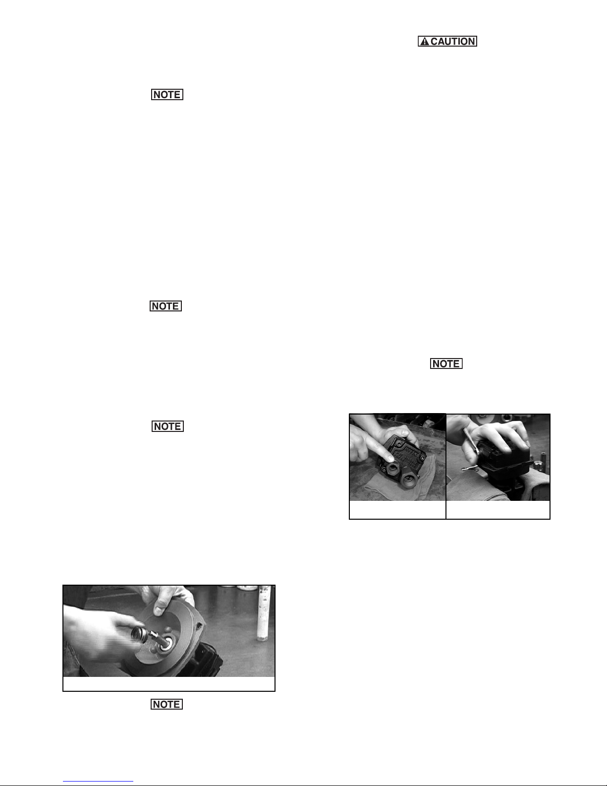
Disassembly and Repair of the Hydraulic Motor
The work area and motor should be as clean as
possible to prevent contamination of parts.
Figure 10
Figure 10a
1. Remove the Mounting Flange from the motor body and
place Hydraulic Motor in vise.
2. Remove Tank Port Adapter and Pressure Port Adapter
with large crescent wrench or 1-1/16” and 1-3/8” box end
wrench (See Figure 10).
Figure 9
On Models 9305C-HM3C-SP, 9505C-HM3C-BS and
9305C-HM3C, install the washer on the shaft prior to
installing the impeller nut.
3. Using a 9/16” box end wrench, loosen the nut on the Bypass Adjusting Screw (See Figure 10a).
4. Using a small screwdriver, remove the Bypass Adjusting
Screw from the Motor. (This will remove the Screw, Nut,
Washer and Thread-Seal Gasket.)
5. Using a 1/4” Allen wrench, remove the Socket Head Cap
Screws from the Motor End Plate (See Figure 10).
6. If Motor End Plate will not lift off easily, use a small screwdriver to carefully pry apart the boss portion of the End
Plate and Gerotor Housing until free (See Figure 11). If
Gerotor Housing will not lift off easily, carefully pry apart
-9-
L-1526 (12/12, Rev. B)
 Loading...