

Page 1
Warning:
1
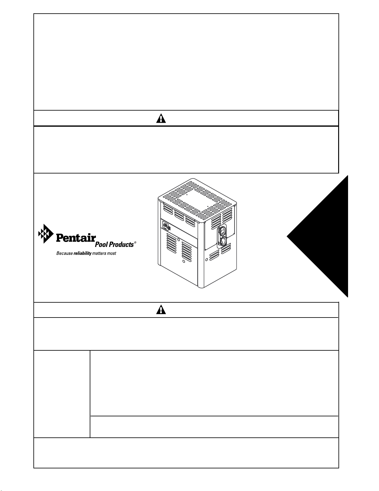
MiniMax® 75 & 100
ABOVEGROUND POOL & SPA HEATERS
OPERATION & INSTALLATION MANUAL
IMPORTANT SAFETY INSTRUCTIONS
READ AND FOLLOW ALL INSTRUCTIONS
SAVE THESE INSTRUCTIONS
WARNING
FOR YOUR SAFETY - READ BEFORE OPERATING
If you do not follow these instructions exactly, a fire or explosion may result,
causing property damage, personal injury or loss of life. Call (800) 831-7133
for additional free copies of these instructions.
Consumer
Retain For
Future
Reference
U.S. Patent Numbers
5,201,307 - 4,595,825
WARNING
Warning: Improper installation, adjustment, alteration, service or maintenance can cause
property damage, personal injury or death. Installation and service must be performed by a
qualified installer, service agency or the gas supplier.
WHAT TO DO IF YOU SMELL GAS
• Do not try to light any appliance.
For Your
Safety
• Do not touch any electrical switch; do not use any phone in your building.
• Immediately call your gas supplier from a neighbor's phone.
Follow the gas supplier's instructions.
• If you cannot reach your gas supplier, call the fire department.
To
Do not store or use gasoline or other flammable vapors and liquids in
the vicinity of this or other appliances.
Pentair Pool Products
1620 Hawkins Ave., Sanford, NC 27330 • (919) 774-4151
10951 West Los Angeles Ave., Moorpark, CA 93021 • (805) 523-2400
Rev. F 1-22-04 P/N 471105
Page 2

2
TABLE OF CONTENTS
Introduction . . . . . . . . . . . . . . . . . . . . . . . . . . . . . . . . . . . . . . . . . . . . . . . . . . . . . . . . . . . . 3
Codes . . . . . . . . . . . . . . . . . . . . . . . . . . . . . . . . . . . . . . . . . . . . . . . . . . . . . . . . . . . . . . . . . . . . . . . . . . . . . . . . . . . . . . 3
Warranty Information . . . . . . . . . . . . . . . . . . . . . . . . . . . . . . . . . . . . . . . . . . . . . . . . . . . . . 4
Operation . . . . . . . . . . . . . . . . . . . . . . . . . . . . . . . . . . . . . . . . . . . . . . . . . . . . . . . . . . . . . . . 4
Safety Rules . . . . . . . . . . . . . . . . . . . . . . . . . . . . . . . . . . . . . . . . . . . . . . . . . . . . . . . . . . . . . . . . . . . . . . . . . . . . . . . . . . 4
Direct Spark Ignition Lighting/Operation - Natural & Propane . . . . . . . . . . . . . . . . . . . 5
Safety Instructions . . . . . . . . . . . . . . . . . . . . . . . . . . . . . . . . . . . . . . . . . . . . . . . . . . . . . . . . . . . . . . . . . . . . . . . . . . . . . 5
Operating Instructions . . . . . . . . . . . . . . . . . . . . . . . . . . . . . . . . . . . . . . . . . . . . . . . . . . . . . . . . . . . . . . . . . . . . . . . . . . 5
To Turn Off Gas to Heater . . . . . . . . . . . . . . . . . . . . . . . . . . . . . . . . . . . . . . . . . . . . . . . . . . . . . . . . . . . . . . . . . . . 5
Millivolt Lighting/Operation - Natural & Propane . . . . . . . . . . . . . . . . . . . . . . . . . . . . . . 6
Safety Instructions . . . . . . . . . . . . . . . . . . . . . . . . . . . . . . . . . . . . . . . . . . . . . . . . . . . . . . . . . . . . . . . . . . . . . . . . . . . . . 6
Lighting Instructions . . . . . . . . . . . . . . . . . . . . . . . . . . . . . . . . . . . . . . . . . . . . . . . . . . . . . . . . . . . . . . . . . . . . . . . . . . . . 6
To Turn Off Gas to Heater . . . . . . . . . . . . . . . . . . . . . . . . . . . . . . . . . . . . . . . . . . . . . . . . . . . . . . . . . . . . . . . . . . . 6
Operating (Controls) . . . . . . . . . . . . . . . . . . . . . . . . . . . . . . . . . . . . . . . . . . . . . . . . . . . . . . . . . . . . . . . . . . . . . . . . . . . 7
Heater Operation . . . . . . . . . . . . . . . . . . . . . . . . . . . . . . . . . . . . . . . . . . . . . . . . . . . . . . . . . . . . . . . . . . . . . . . . . . . . . . 7
General . . . . . . . . . . . . . . . . . . . . . . . . . . . . . . . . . . . . . . . . . . . . . . . . . . . . . . . . . . . . . . . . . . . . . . . . . . . . . . . . . 7
Controls Operation . . . . . . . . . . . . . . . . . . . . . . . . . . . . . . . . . . . . . . . . . . . . . . . . . . . . . . . . . . . . . . . . . . . . . . . . . 7
Maintenance . . . . . . . . . . . . . . . . . . . . . . . . . . . . . . . . . . . . . . . . . . . . . . . . . . . . . . . . . . . 10
Maintenance Instructions . . . . . . . . . . . . . . . . . . . . . . . . . . . . . . . . . . . . . . . . . . . . . . . . . . . . . . . . . . . . . . . . . . . . . . . 10
Energy Saving Tips . . . . . . . . . . . . . . . . . . . . . . . . . . . . . . . . . . . . . . . . . . . . . . . . . . . . . . . . . . . . . . . . . . . . . . . . 10
Spring and Fall Operation . . . . . . . . . . . . . . . . . . . . . . . . . . . . . . . . . . . . . . . . . . . . . . . . . . . . . . . . . . . . . . . . . . . 10
Winter Operation . . . . . . . . . . . . . . . . . . . . . . . . . . . . . . . . . . . . . . . . . . . . . . . . . . . . . . . . . . . . . . . . . . . . . . . . . 10
Chemical Balance . . . . . . . . . . . . . . . . . . . . . . . . . . . . . . . . . . . . . . . . . . . . . . . . . . . . . . . 11
Pool and Spa Water . . . . . . . . . . . . . . . . . . . . . . . . . . . . . . . . . . . . . . . . . . . . . . . . . . . . . . . . . . . . . . . . . . . . . . . . . . . 11
Installation Instructions . . . . . . . . . . . . . . . . . . . . . . . . . . . . . . . . . . . . . . . . . . . . . . . . . . 12
Specifications . . . . . . . . . . . . . . . . . . . . . . . . . . . . . . . . . . . . . . . . . . . . . . . . . . . . . . . . . . . . . . . . . . . . . . . . . . . . . . . . 12
Outdoor Installation . . . . . . . . . . . . . . . . . . . . . . . . . . . . . . . . . . . . . . . . . . . . . . . . . . . . . . . . . . . . . . . . . . . . . . . . . . . 12
Indoor Installation . . . . . . . . . . . . . . . . . . . . . . . . . . . . . . . . . . . . . . . . . . . . . . . . . . . . . . . . . . . . . . . . . . . . . . . . . . . . . 12
Plumbing Connections . . . . . . . . . . . . . . . . . . . . . . . . . . . . . . . . . . . . . . . . . . . . . . . . . . . 13
Manual Bypass . . . . . . . . . . . . . . . . . . . . . . . . . . . . . . . . . . . . . . . . . . . . . . . . . . . . . . . . . . . . . . . . . . . . . . . . . . . . . . . 13
Valves. . . . . . . . . . . . . . . . . . . . . . . . . . . . . . . . . . . . . . . . . . . . . . . . . . . . . . . . . . . . . . . . . . . . . . . . . . . . . . . . . . . . . . 13
Pressure Switch . . . . . . . . . . . . . . . . . . . . . . . . . . . . . . . . . . . . . . . . . . . . . . . . . . . . . . . . . . . . . . . . . . . . . . . . . . . . . . 13
Water Connections . . . . . . . . . . . . . . . . . . . . . . . . . . . . . . . . . . . . . . . . . . . . . . . . . . . . . . 14
Quick-Flange II Installation Instructions . . . . . . . . . . . . . . . . . . . . . . . . . . . . . . . . . . . . . . . . . . . . . . . . . . . . . . . . . . . . . 14
Gas Connections . . . . . . . . . . . . . . . . . . . . . . . . . . . . . . . . . . . . . . . . . . . . . . . . . . . . . . . 15
Gas Line/Installation . . . . . . . . . . . . . . . . . . . . . . . . . . . . . . . . . . . . . . . . . . . . . . . . . . . . . . . . . . . . . . . . . . . . . . . . . . . 15
Pipe Sizing Chart/Gas Pressure Requirements . . . . . . . . . . . . . . . . . . . . . . . . . . . . . . . . . . . . . . . . . . . . . . . . . . . . . . . 15
Regulated Manifold Pressure Test . . . . . . . . . . . . . . . . . . . . . . . . . . . . . . . . . . . . . . . . . . . . . . . . . . . . . . . . . . . . . . . . 15
Gas Pressure Settings . . . . . . . . . . . . . . . . . . . . . . . . . . . . . . . . . . . . . . . . . . . . . . . . . . . . . . . . . . . . . . . . . . . . . . . . . 15
Ventilation . . . . . . . . . . . . . . . . . . . . . . . . . . . . . . . . . . . . . . . . . . . . . . . . . . . . . . . . . . . . . 16
Outdoor Installation . . . . . . . . . . . . . . . . . . . . . . . . . . . . . . . . . . . . . . . . . . . . . . . . . . . . . . . . . . . . . . . . . . . . . . . . . . . 16
Indoor Installation . . . . . . . . . . . . . . . . . . . . . . . . . . . . . . . . . . . . . . . . . . . . . . . . . . . . . . . . . . . . . . . . . . . . . . . . . . . . . 17
Vent Test . . . . . . . . . . . . . . . . . . . . . . . . . . . . . . . . . . . . . . . . . . . . . . . . . . . . . . . . . . . . . . . . . . . . . . . . . . . . . . . . . . . 18
Stack Type Indoor Draft Hood Kit . . . . . . . . . . . . . . . . . . . . . . . . . . . . . . . . . . . . . . . . . . . . . . . . . . . . . . . . . . . . . . . . . 18
Indoor Draft Hood Kit . . . . . . . . . . . . . . . . . . . . . . . . . . . . . . . . . . . . . . . . . . . . . . . . . . . . . . . . . . . . . . . . . . . . . . . . . . 18
Electrical . . . . . . . . . . . . . . . . . . . . . . . . . . . . . . . . . . . . . . . . . . . . . . . . . . . . . . . . . . . . . . 18
Transformer Wiring Instruction . . . . . . . . . . . . . . . . . . . . . . . . . . . . . . . . . . . . . . . . . . . . . . . . . . . . . . . . . . . . . . . . . . . 18
Electronic Direct Spark Ignition Wiring Diagram . . . . . . . . . . . . . . . . . . . . . . . . . . . . . . . . . . . . . . . . . . . . . . . . . . . . . . 19
Millivolt Wiring Diagram. . . . . . . . . . . . . . . . . . . . . . . . . . . . . . . . . . . . . . . . . . . . . . . . . . . . . . . . . . . . . . . . . . . . . . . . . 19
Trouble Shooting (General). . . . . . . . . . . . . . . . . . . . . . . . . . . . . . . . . . . . . . . . . . . . . . . 20
Parts List & Exploded View . . . . . . . . . . . . . . . . . . . . . . . . . . . . . . . . . . . . . . . . . . . . 21, 22
Warranty Information . . . . . . . . . . . . . . . . . . . . . . . . . . . . . . . . . . . . . . . . . . . . . . . . . . . . . 23
P/N 471105 Rev. F 1-22-04
Page 3
3
Introduction
MiniMax® 75 & 100
ABOVEGROUND POOL AND SPA HEATERS
Congratulations on your purchase of a MiniMax 100 high performance heating system. Proper installation and
service of your new heating system and correct chemical maintenance of the water will ensure years of enjoyment.
The MiniMax 100 is a compact, lightweight and efficient gas fired high performance aboveground pool and spa
heater that can be connected to schedule 40 CPVC or ABS pipe and has a built-in top. Unless noted otherwise, all
instructions refer to both the MiniMax 75 and MiniMax 100 heaters designated collectively as the "MiniMax 100".
The heater features include the following features.
• Reliable direct-spark ignition (DSI) system available in propane or natural gas versions.
• Millivolt standing pilot versions in propane and natural gas, when no convenient line power is present.
• Fuel gas input of 100,000 btu/hr with thermal efficiency in excess of 82%, (74,999 for the 75 Model).
• Quiet and dependable operation from packaged burner system proven reliable in worldwide usage.
• Heat exchanger constructed of premium non-corroding materials including bronze headers standard.
• The controls have been designed to be very easy to troubleshoot and very easy to access and replace in the
rare event of a malfunction-making the MiniMax 100 user friendly.
IMPORTANCE NOTICES FOR THE INSTALLER AND OPERATOR.
The manufacturer’s warranty may be void if, for any reason, the heater is improperly installed and /or operated.
Be sure to follow the instructions set forth in this manual.
These heaters are designed for the heating of swimming pools and spas, and should never be employed for use as
space heating boilers, general purpose water heaters, or for the heating of salt water.
CODES
The installation must conform with local codes or in the absence of local codes with the latest National Fuel Gas
Code, ANSI Z223.1, and the latest edition of the National Electrical Code, NFPA 70.
Installation in Canada to be made in accordance with the latest CAN/CGA-B149.1 or .2 and CSA C22.1
Canadian Electric Code, part 1.
Rev. F 1-22-04 P/N 471105
Page 4
4
This instruction manual provides operating instructions, installation, and service information for the MiniMax 100
high performance heater. The information in this manual applies to the MiniMax 75, and 100, natural gas and
propane, DSI; and MiniMax 100 millivolt standing pilot heater models.
It is very important the owner/installer read and understand the section covering installation and recognize the
local code and state codes before installing the MiniMax 100. History and experience have shown that
most heater damage is caused by improper installation practices.
WARRANTY INFORMATION
The MiniMax 100 pool heater is sold with a limited factory warranty. Specific details are described on the
back cover of this manual and a copy of the warranty and warranty registration card are included with
the product. Return the warranty registration card after filling in the serial number from the rating plate inside the
heater. For ordering parts, you should indicate model and serial numbers of the heater. If the parts are
requested for warranty, you must also indicate the date of installation.
Pentair Pool Products high standards of excellence include a policy of continuous product
improvement resulting in your state-of-the-art heater. We reserve the right to make improvements
which change the specifications of the heater without incurring an obligation to update current heater
equipment.
Operation
SAFETY RULES
1. Spa or hot tub water temperatures should never
exceed 104 °F (40 °C). A temperature of 100 °F
(38 °C) is considered safe for a healthy adult.
Special caution is suggested for young children.
2. Drinking of alcoholic beverages before or
during spa or hot tub use can cause drowsiness
which could lead to unconsciousness and
subsequently result in drowning.
3. Pregnant women beware! Soaking in water
above 102° F. (39° C.) can cause fetal damage
during the first three months of pregnancy
(resulting in the birth of a brain-damaged or
deformed child). Pregnant women should stick
to the 100° F. (38° C.) maximum rule.
4. Before entering the spa or hot tub, the user should
check the water temperature with an accurate
thermometer. Spa or hot tub thermostats may err
in regulating water temperatures by as much as
4° F. (2.2° C.).
5. Persons with medical history of heart disease,
circulatory problems, diabetes or blood pressure
problems should obtain their physician's advice
before using spas or hot tubs.
6. Persons taking medication which induce
drowsiness, such as tranquilizers, antihistamines or
anticoagulants should not use spas or hot tubs.
WARNING
Should overheating occur or the gas supply fail to shut off, turn off the manual gas control valve to the
appliance. Do not use this heater if any part has been under water. Immediately call a qualified service
technician to inspect the heater and to replace any part of control system and gas control which has
been under water.
P/N 471105 Rev. F 1-22-04
Page 5
Operation (contd.)
MINIMAX 100 DIRECT-SPARK IGNITION LIGHTING/OPERATIONNATURAL GAS & PROPANE
FOR YOUR SAFETY: READ BEFORE LIGHTING
WARNING
If you do not follow these instructions exactly, a fire or explosion may result causing personal injury,
loss of life and property damage.
Since propane gas is heavier than air, escaping propane will accumulate and remain at ground level.
Do not attempt to light the heater. If you suspect a propane leak, lighting the heater can result in a fire
or explosion which can cause personal injury, death, and property damage.
5
A. This heater is equipped with an ignition device
which automatically lights the main burner. Do not
try to light the main burner by hand.
B. BEFORE OPERATING smell all around the heater
area for gas. Be sure to smell next to the floor
because some gas is heavier than air and will settle
on the floor.
WHAT TO DO IF YOU SMELL GAS
- Do not try to light any heater.
- Do not touch any electric switch; do not use any
phone in your building.
- Immediately call your gas supplier from a neighbor's
phone. Follow the gas supplier's instructions.
- If you cannot reach your gas supplier, call the Fire
Department.
C. Use only your hand to push in or turn the gas
control knob. Never use tools. If the knob will not
push in or turn by hand, don't try to repair it. Call a
qualified service technician. Forced or attempted
repair may result in a fire or explosion.
D. Do not use this heater if any part has been under
water. Immediately call a qualified service
technician to inspect the heater and to replace any
part of the control system and any gas control
which has been under water.
OPERATING INSTRUCTIONS
1. STOP! Read the safety information above.
2. Set the thermostat to lowest setting, fully counterclockwise.
3. Turn off electric power to the heater.
4. This heater is equipped with an ignition device which automatically lights
the main burner. Do not try to light the main burner by hand.
5. Remove the control access door.
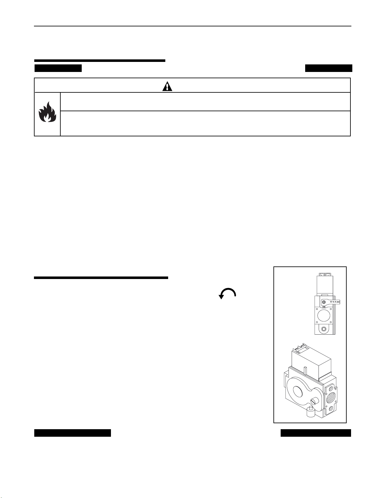
6. Turn the gas control lever horizontally to "OFF"; see Figure 1.
7. Wait five (5) minutes to clear out any gas. If you then smell gas, STOP!
Follow "B" in the safety information above. If you don't smell gas, go to the
next step.
8. Turn the gas control lever vertically to "ON".
9. Replace the control access door.
10. Turn on the electrical power to the heater.
11. Set the thermostat to the desired setting.
12. If the heater will not operate, follow the instructions "To Turn Off Gas To
Heater" and call your service technician or gas supplier.
Figure 1.
TO TURN OFF GAS TO HEATER
1. Set the thermostat to lowest setting.
2. Turn off all electric power to the heater if service
is to be performed.
3. Remove control access door.
Rev. F 1-22-04 P/N 471105
4. Turn gas control lever horizontally to "OFF".
Do not force.
5. Replace control access door.
Page 6
Operation (contd.)
MILLIVOLT LIGHTING/OPERATION- NATURAL GAS & PROPANE
FOR YOUR SAFETY: READ BEFORE LIGHTING
WARNING
If you do not follow these instructions exactly, a fire or explosion may result causing personal injury,
loss of life and property damage.
Since propane gas is heavier than air, escaping propane will accumulate and remain at ground level. Do
not attempt to light the heater. If you suspect a propane leak, lighting the heater can result in a fire or
explosion which can cause personal injury, death, and property damage.
6
A. This heater has a pilot that must be lit manually. When
lighting the pilot follow these instructions exactly.
B. BEFORE LIGHTING smell all around the heater area
for gas. Be sure to smell next to the floor because some
gas is heavier than air and will settle on the floor.
WHAT TO DO IF YOU SMELL GAS
- Do not try to light any heater.
- Do not touch any electric switch; do not use any phone
in your building.
- Immediately call your gas supplier from a neighbor's
phone. Follow the gas supplier's instructions.
- If you cannot reach your gas supplier, call the Fire
Department.
C. Use only your hand to push in or turn the gas control
knob. Never use tools. If the knob will not push in or
turn by hand, don't try to repair it. Call a qualified service
technician. Forced or attempted repair may result in a
fire or explosion.
D. Do not use this heater if any part has been under water.
Immediately call a qualified service technician to inspect
the heater and to replace any part of the control system
and any gas control which has been under water.
LIGHTING INSTRUCTIONS
1. STOP! Read the safety information above.
2. Set the thermostat to the lowest setting.
3. Turn off all electric power to the heater.
4. Remove the control access door.
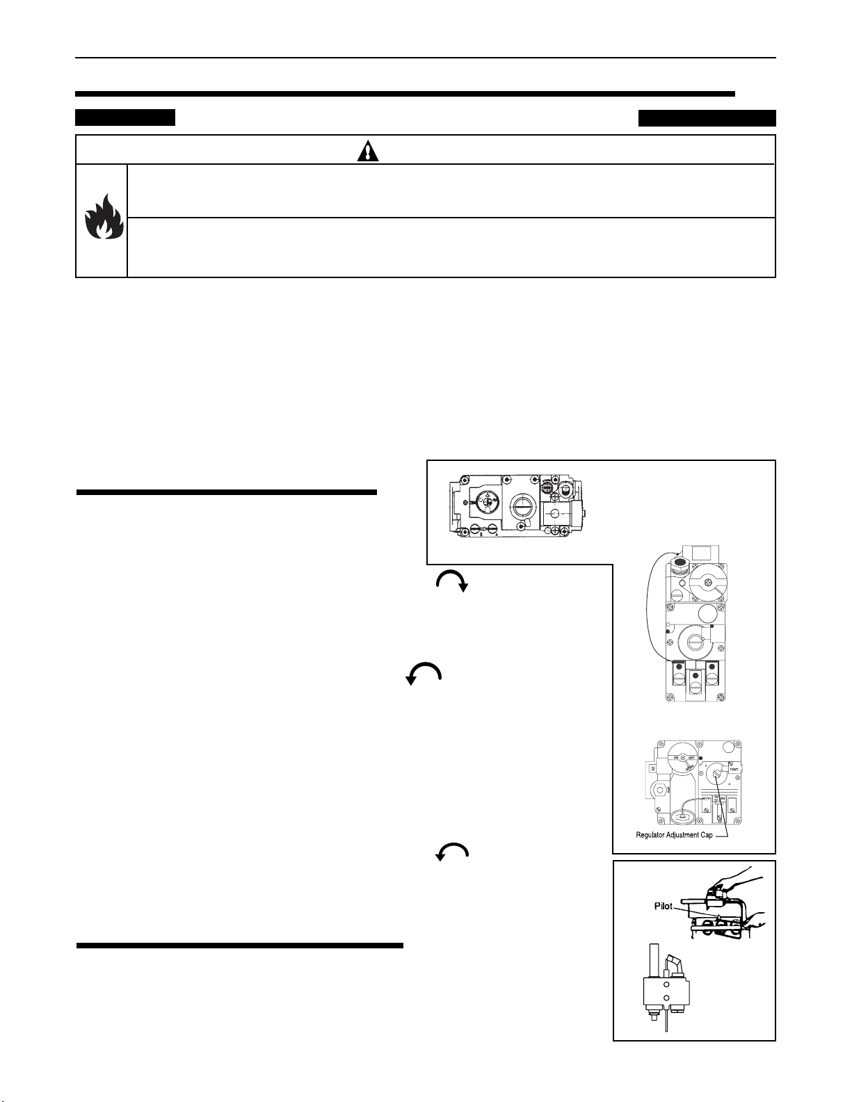
5. Push in the gas control valve slightly and turn clockwise to "OFF"; see Figure 2.
6. The knob cannot be turned from "PILOT" to "OFF" unless the knob is
pushed in slightly. Do not force.
7. Wait five (5) minutes to clear out any gas. If you then smell gas, STOP! Follow "B" in the
safety information above. If you don't smell gas, go to next step.
8. Turn the knob on the gas control to counterclockwise to "PILOT"; see Figure 3.
9. Push the control knob all the way and hold in. Immediately light the pilot with
Presslite matchless ignition system by pressing the red igniter button, (located at
panel next to the gas valve). Continue to hold the control knob in for about (1)
minute after the pilot is lit. Release knob and it will pop back up. Pilot should remain
lit. If it goes out, repeat steps 4 through 7.
10. If the knob does not pop up when released, stop and immediately call your service
technician or gas supplier.
11. If the pilot, see Figure 4, will not stay lit after several tries, turn the gas control knob
to "OFF" and call your service technician or gas supplier.
12. Turn the gas control knob counterclockwise to "ON".
13. Replace the control access door.
14. If the heater will not operate, follow the instructions "To Turn Off Gas To Heater"
and call your service technician or gas supplier.
(SIT valve)
Figure 2.
All Gas knob's shown
in "OFF" position.
IN
PILOT ADJ
ON
OFF
VENT
TH
TH
TP
TP
(Robertshaw valves)
Figure 3.
TO TURN OFF GAS TO HEATER
1. Set the thermostat to lowest setting.
2. Turn off all electric power to the heater if service is to be performed.
3. Remove control access door.
4. Turn gas control lever horizontally to "OFF". Do not force.
5. Replace control access door.
P/N 471105 Rev. F 1-22-04
Figure 4.
Page 7
Operation (contd.)
7
OPERATING (CONTROLS)
DIRECT SPARK ELECTRONIC AND
MILLIVOLT MODELS
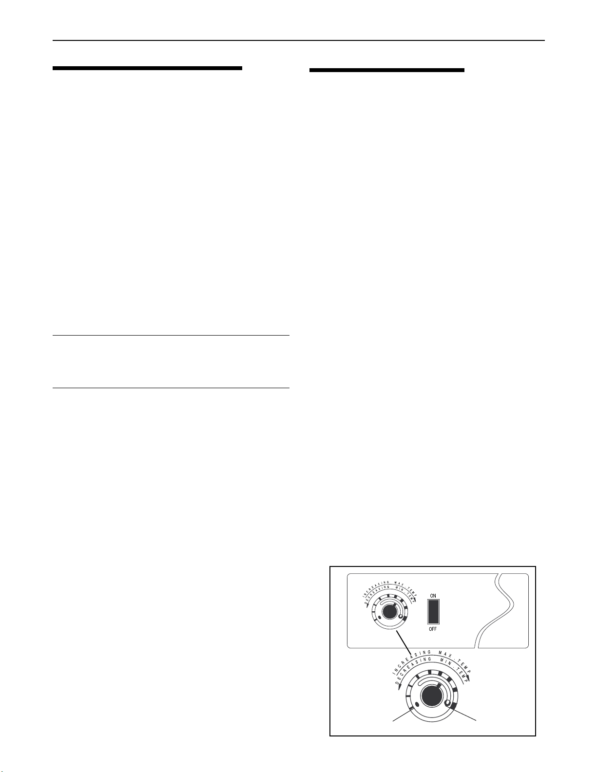
For convenience and economy all MiniMax 100
heaters are equipped with a thermostat on the front of
the heater control panel; see Figure 5.
Direct Spark MiniMax 100 heaters are equipped
with an electronic thermostat while Millivolt MiniMax
100 heaters have a mechanical thermostat.
The Pool/Off/Spa switch allows the heater to be turned
off when heating is not desired.
1. "ON" position - Maintains selected pool temperature.
2. "OFF" position - Heater will not come on regardless
of drop in pool temperature.
THERMOSTAT ADJUSTMENT
The knob with locking feature eliminates the need for
constant thermostat adjustments. Set the knob pointer
to the desired spa temperature.
NOTE
To eliminate error due to piping heat losses
measure pool temperature with an accurate
thermometer directly at the pool or spa.
If further adjustment is needed rotate the knob until
the desired temperature is obtained. This knob position
corresponding to your desired maximum pool or spa
temperature may now be preset (locked) by the knob
stopper which prevents the knob from being turned
beyond the maximum temperature you set.
THERMOSTAT KNOB STOPPER
Each thermostat is equipped with a mechanical stop
that can be locked or unlocked with use of a screwdriver to prevent temperatures in excess of that
desired by the user; see Figure 5.
The maximum setting can be adjusted by loosening
the screw "A" and turning the stopper dial to desired
maximum setting. Lock the setting by tightening the
screw. The Mechanical stop is under the knob.
Ensure that the knob is stopping at the correct position when the knob is rotated clockwise from a lower
temperature position.
HEATER OPERATION
GENERAL
The MiniMax 100 DSI employs a microprocessor
based Direct Spark Ignition (DSI) system to light the
main burner and therefore has no pilot. The ignition
circuit operates at 24 VAC and requires that line
voltage 115/230 be supplied to the heater.
The MiniMax 100 MV (Millivolt) requires no external
power source and the control circuit derives all its
power from the energy generated from the standing
pilot/ thermopile-generator combination. Note: Some
states ,including California, have energy conservation
regulations preventing the sale and use of certain
standing pilot (millivolt) equipment.
The MiniMax 100 DSI Control utilizes a
microprocessor to continually and safely monitor,
analyze, and control the proper operation of the gas
burner. The DSI Control features LED diagnostics,
automatic one hour reset, and flame current test pins.
The LED is located on the DSI.
CONTROLS OPERATION (DSI SYSTEM)
Heat Mode
1. When a call for heat is received from the thermostat
supplying 24 volts to TH terminal on control, the
control will reset, perform a self check routine, and
flash the diagnostic LED for up to four seconds.
After a brief delay the gas valve is energized and
the ignition electrode begins to spark for the four
(4) second trial for ignition (TFI) period.
2. When flame is detected during the trial for ignition,
sparking is shut-off immediately and the gas valve
remains energized. The thermostat and main burner
flame are constantly monitored to assure the system
continues to operate properly.
a.When the thermostat is satisfied and the demand
for heat ends, the main valve is de-energized
immediately.
Figure 5.
Knob Stopper
Rev. F 1-22-04 P/N 471105
Screw A
Page 8
Operation - Heater (contd.)
Failure to Light- Lockout
1. Should the main burner fail to light, or flame is not
detected during the trial-for-ignition (TFI) period
the control will go into lockout and the valve will
be turned off immediately.
2. Recovery from lockout requires a manual reset by
resetting the thermostat or turning off the ON/OFF
switch for a minimum period of 5 seconds.
IMPORTANT!
IT IS RECOMMENDED THAT NO MORE THAN
TWO IGNITION ATTEMPTS IN SUCCESSION
BE PERFORMED FOR NATURAL GAS
SYSTEMS . BEFORE FURTHER IGNITION
ATTEMPTS WAIT AT LEAST FIVE MINUTES
FOR GAS TO CLEAR.
FOR PROPANE (LPG) SYSTEMS ALLOW AT
LEAST FIVE (5) MINUTES BETWEEN IGNITION
ATTEMPTS FOR THIS HEAVIER-THAN-AIR
GAS TO SAFELY DISSIPATE. AFTER TWO
UNSUCCESSFUL IGNITION ATTEMPTS WITH
PROPANE OPEN THE BURNER ACCESS
DOOR AND WAIT AT LEAST THIRTY (30)
MINUTES BEFORE REPLACING DOOR TO
ATTEMPT FURTHER IGNITION ATTEMPTS.
8
Control Fault -Diagnostic LED Conditions
Error Mode LED Indication
Internal Control Failure Steady on
Flame Sense Fault 2 flashes
Ignition Lockout 3 flashes
The DSI Ignition Control can be accessed after removing
the heater’s front control panel. The diagnostic LED
located on the top of the DSI control will flash on for 1/4
second, then off for 1/4 second during a fault condition.
The pause between fault codes is 3 seconds.
NOTE
Normally the heater will light in the first or
second attempt. And with the exception of
a new installation or one that has been
shut down for an extended period, where
there is considerable air trapped in the gas
supply line, unsuccessful ignition
indicates other problems with the ignition
system - such as an unclean ignition
electrode impeding flame sensing.
3. If the thermostat is still calling for heat one hour
after a lockout the control will automatically reset
and attempt to ignite the burner again.
Flame Failure-Re-Ignition
1. If the established flame signal is lost while the
burner is operating, the control will respond within
0.8 seconds. The H.V. spark will be energized for a
trial for ignition period in an attempt to relight the
burner.
a. If the burner does not light the control will
de-energize the gas valve, shutting off the gas
flow, and the control will go into lockout as
described above in “Failure to Light-Lockout”.
If flame is re-established, normal operation
resumes.
P/N 471105 Rev. F 1-22-04
Page 9

Operation - Heater (contd.)
9
Proper Electrode Location
Proper location of the ignition electrode assembly is
important for optimum and safe system performance.
The electrode assembly should be located as noted in
Figure 6. The electrode assembly is NOT field
repairable and must be replaced if damaged.
Service Checks
Symptom Cause/Cure
1. Dead A. Miswired
B. Transformer bad
C. Fuse/circuit breaker open
D. Bad control (check LED for steady on)
2. Thermostat on, A. Miswired
no spark B. Bad thermostat no voltage @
terminal TH
3. Valve on, no spark A. Shorted Ign. electrode
B. Open HV Ign cable
C. Miswired
D. Bad DSI control
4. Spark on, no valve A. Valve coil open
B. Open valve wire
C. Bad control (also check voltage
between V1 & V2)
5. Flame okay during A. Bad electrode
TFI, no flame sense B. Bad S1 or HV wire
(after TFI) C. Poor ground at burner
D. Poor flame (check flame sensor
current, which follows)
Flame Sensor Current Check
Flame current is the current which passes through
the flame sensor to ground. The minimum flame
current necessary to keep system from lockout is 0.7
microamperes. To measure flame current, connect
DC microammeter to the FC- FC+ terminals as
shown in Figure 7. The meter should read 0.7
microamperes or higher when the heater is firing.
Figure 7.
Figure 6.
Rev. F 1-22-04 P/N 471105
Page 10

Maintenance
MAINTENANCE INSTRUCTIONS
It is recommended that you check the following items
at least every six months and at the beginning of every
swimming season.
1. Examine the venting system. Make sure there are
no obstructions in the flow of combustion and
ventilation air.
2. Visually inspect the main burner and the pilot
burner flame (on millivolt models). The normal
color of the flame is blue. When flame appears
yellow, burners should be inspected and cleaned;
see Figure 8.
3. Keep the burner area clear and free from combustibles and flammable liquids.
ENERGY SAVING TIPS
1. If possible, keep pool or spa covered when not in
use. This will not only cut heating costs, but also
keep dirt and debris from settling in the pool and
conserve chemicals.
2. Reduce the pool thermostat setting to 78
lower. This is accepted as being the most healthy
temperature for swimming by the American Red
Cross.
3. Use an accurate thermometer.
4. When the proper maximum thermostat settings
have been determined, tighten the thermostat knob
stopper.
5. Set time clock to start circulation system no earlier
than daybreak. The swimming pool loses less heat
at this time.
6. For pools that are only used on the weekends, it is
not necessary to leave the thermostat set at 78
Lower the temperature to a range that can be
achieved easily in one day. Generally, this would
° F. to 15° F., if pool heater is sized properly.
be 10
7. During the winter or while on vacation, turn heater
off.
8. Set up a regular program of preventative
maintenance for the heater each new swimming
season. Check heat exchanger, controls, burners,
operation, etc.
° F. or
°F.
10
Blue Flame
Figure 8.
SPRING AND FALL OPERATION
If the pool is being used occasionally, do not turn the
heater completely off. Set the thermostat down to
° F. This will keep the pool and the surrounding
65
ground warm enough to bring the pool up to a comfortable swimming temperature in a shorter period of
time.
WINTER OPERATION
If the pool won't be used for a month or more, turn
the heater off at the main gas valve. For areas where
there is no danger of water freezing, water should
circulate through the heater all year long, even though
you are not heating your swimming pool. This heater
should not be operated out doors at temperatures
below 32° F. (0° C.). Where freezing is possible, it is
necessary to drain the water from the heater. This
may be done by opening the drain valve located at the
inlet/outlet header allowing all water to drain out of
the heater. It would be a good practice to use
compressed air to blow the water out of the heat
exchanger.
P/N 471105 Rev. F 1-22-04
Page 11

Maintenance (contd.)
11
CHEMICAL BALANCE
POOL AND SPA WATER
Your Pentair Pool Products pool heater was designed
specifically for your spa or pool and will give you many
years of trouble free service provided you keep your
water chemistry in proper condition.
Three major items that can cause problems with your
pool heater are improper pH, disinfectant residual, and
If pH becomes too high (over alkaline), it
has these effects:
1. Greatly lowers the ability of chlorine to destroy
bacteria and algae.
2. Water becomes cloudy.
3. There is more danger of scale formation on the
plaster or in the heat exchanger.
4. Filter elements may become blocked.
total alkalinity. These items, if not kept properly
balanced, can shorten the life of the heater and cause
permanent damage.
WARNING
If pH is too low (over acid) the following
conditions may occur:
1. Excessive eye burn or skin irritation.
2. Etching of the plaster.
Heat exchanger damage resulting from chemical
imbalance is not covered by the warranty.
WHAT A DISINFECTANT DOES
Two pool guests you do not want are algae and
bacteria. To get rid of them and make pool water
sanitary for swimming - as well as to improve the
water's taste, odor and clarity - some sort of
disinfectant must be used.
Chlorine and bromine are universally approved by
health authorities and are accepted disinfecting agents
for bacteria control.
WHAT IS A DISINFECTANT
RESIDUAL?
When you add chlorine or bromine to the pool water, a
portion of the disinfectant will be consumed in the
process of destroying bacteria, algae and other oxidiz-
3. Corrosion of metal fixtures in the filtration and
recirculation system, which may create brown, blue,
green, or sometimes almost black stains on the
plaster.
4. Corrosion of copper in the heater, which may cause
leaks.
5. If you have a sand and gravel filter, the alum used
as a filter aid may dissolve and pass through the
filter.
CAUTION: Do not test for pH when the chlorine
residual is 3.0 ppm or higher, or bromine residual is
6.0 ppm or higher. See your local pool supply store
for help in properly balancing your water chemistry.
RULE: Chemicals that are acid lower pH. Chemicals
that are alkaline raise pH.
ALKALINITY High - Low:
able materials. The disinfectant remaining is called
chlorine residual or bromine residual. You can determine the disinfectant residual of your pool water with a
reliable test kit, available from your local pool supply
store.
You must maintain a disinfectant residual level
adequate enough to assure a continuous kill of bacteria
or virus introduced into pool water by swimmers,
through the air, from dust, rain or other sources.
It is wise to test pool water regularly. Never allow
chlorine residual to drop below 0.6 ppm (parts per
million). The minimum level for effective chlorine or
bromine residual is 1.4 ppm.
pH - The term pH refers to the acid/alkaline balance of
water expressed on a numerical scale from 0 to 14. A test
kit for measuring pH balance of your pool water is
"Total alkalinity" is a measurement of the total amount
of alkaline chemicals in the water, and control pH to a
great degree. (It is not the same as pH which refers
merely to the relative alkalinity/acidity balance.) Your
pool water's total alkalinity should be 100 - 140 ppm to
permit easier pH control.
A total alkalinity test is simple to perform with a reliable
test kit. You will need to test about once a week and make
proper adjustments until alkalinity is in the proper range.
Then, test only once every month or so to be sure it is
being maintained. See your local pool dealer for help in
properly balancing the water chemistry.
Table 1.
Strongly Acid Neutral Strongly Alkaline
0 1 2 3 4 5 6 7 8 9 10 11 12 13 14
pH Chart
available from your local pool supply store; see Table 1.
Muriatic Acid has a pH of about 0. Pure water is 7
Table 2.
(neutral). Weak Lye solution have a pH of 13-14.
RULE: 7.4 to 7.6 is a desirable pH range. It is essential to maintain correct pH, see Table 2.
Rev. F 1-22-04 P/N 471105
Add Soda Ash or
Sodium Bicarbonate
pH Control Chart
7.26.8 7.0 7.4 7.6 7.8
MarginalIdealMarginal
8.0 8.2 8.4
Add Acid
Page 12

12
COLD
POOL TEMP
HOT
OFF
ON
Installation Instructions
SPECIFICATIONS
IMPORTANT NOTICE: These installation instructions are designed for use by qualified personnel only,
trained especially for installation of this type of heating equipment and related components. Some states require
installation and repair by licensed personnel. If this applies in your state, be sure your contractor bears the
appropriate license.
The heater must be installed on a level surface consisting entirely of, or a combination of, noncombustible
materials such as steel, iron, brick, tile, concrete, slate, or plaster. Do not install on carpeting. The heater must be
installed to keep specific clearances on all sides for service and inspection.
OUTDOOR INSTALLATION
Stackless, applies to all
MiniMax 100 outdoor models
25 1/2"
ON
HOT
COLD
OFF
POOL TEMP
INDOOR INSTALLATION
Applies to all MiniMax 100
indoor models,
Draft hood stack diameter = 5 in.
Stack (USA only)
Outdoor shelter (Canadian)
18 3/8"
15"
5"
14 1/4"
19 11/32"
15 1/2"
Outdoor Installation
Indoor Installation
P/N 471105 Rev. F 1-22-04
Page 13

Installation (contd.)
MiniMax 100
High Performance Heater
COLD
POOL TEMP
HOT
OFF
ON
PacFab
GATE VALVE
PUMP
GATE VALVE
FILTER
HEATER
FROM POOL
VALVE
CHECK
TO POOL
13
PLUMBING CONNECTIONS
The MiniMax 100 heater has the unique capability of
direct schedule 40 or 80 CPVC/ABS/PVC plumbing
connections. Either a Quick-Flange or Quick-Flange II
(depending on model ordered) has been included with the
MiniMax 100 to insure conformity with Pentair Pool
Products recommended CPVC/ABS plumbing procedure;
see Figure 9. Other plumbing connections can be used.
The instructions on the following pages show the methods
for successfully connecting plumbing to the inlet/outlet
header with either the Quick-Flange or Quick-Flange II.
PRESSURE SWITCH
The pressure switch will keep the circuit open when the
pump is not on and operating. When the filter pump
turns on, the pressure switch closes the circuit and the
heater will operate. When the heater is installed below
water level of a spa or pool, adjustment of the pressure
switch may be required. For adjustment of pressure
switch, we recommend the following procedures.
1. Backwash the filter and clean the pump hair and
lint basket before making any adjustment to the
pressure switch.
2. Switch the circulation pump on and make sure it
is primed.
3. Push the heater power switch on and set the
thermostats to their highest temperature settings.
4. Clean the locktight off of the pressure switch
adjustment knob threads.
5. Turn the adjustment knob clockwise or away
from the micro-switch, until the heater shuts
down; see Figure 11.
6. Turn the adjustment knob counter-clockwise 1/2
turn and the heater should refire.
Figure 9.
7. Turn the pump off
and the heater should
shut down. If the
Adjustment
Knob
heater does not shut
MANUAL BY-PASS
down, repeat the
procedure.
Where the flow rate exceeds the maximum 80 GPM, a
manual by-pass should be installed and adjusted. After
adjustments are made, the valve handle should be
removed to avoid tampering.
8. Switch the pump off
and on several times
to assure proper
Figure 11.
adjustment.
Model Min. Max.*
100 20 80
* Do not exceed the maximum recommended
flow rate for the connecting piping.
VALVES
When any equipment is located below the surface of
the pool or spa, valves should be placed in the
circulation piping system to isolate the equipment from
the pool or spa.
Check valves are recommended to prevent back
siphon; see Figure 10.
Caution: Exercise care when installing chemical
feeders so as to not allow back siphoning of
chemical into the heater, filters or pump.
Rev. F 1-22-04 P/N 471105
Figure 10.
Page 14

Installation (contd.)
WATER CONNECTIONS
QUICK-FLANGE II INSTALLATION INSTRUCTIONS
FOR 1½ SCHEDULE 40 CPVC or ABS PIPE or SCHEDULE 80 PVC
(you may adapt to SCH 40 PVC 12 inches beyond the Quick Flange II)
(1½ in. npt x 1½ in. CPVC/ABS slip male adaptor may be required )
Figure 12.
14
1. Insert 2 in. rubber gaskets over 2 in. gasket retainer rings molded to bottom of Quick-Flange II;
see Figure 12.
2. Bolt Quick-Flange II to header using supplied 3/8 in. bolts and 3/8 in. washers.
3. Using pipe dope, thread pipe directly to Quick-Flange II.
a. Or, first thread a 1½ in. npt x 1½ in. slip CPVC/ABS male adaptor (not supplied) to the
Quick-Flange II ,and after preparing the joint by sanding with a medium grit sandpaper,
glue the pipe to the adaptor with a quality solvent glue.
NOTE
ALL VERSIONS OF THE MINIMAX 100 INCLUDE A QUICK-FLANGE II ADAPTOR
Each MiniMax 100 Quick-Flange II Accessory Kit, p/n 471083,
contains the following items:
One (1) Quick-Flange II unit
Two (2) 2 in. Rubber Gaskets
Four (4) 3/8 in. Bolts
Four (4) 3/8 in. Washers
PRESSURE RELIEF VALVES
Where local, (or Canadian), codes require the use of a Pressure Relief Valve (PRV), the PRV may be
installed in a tee fitting placed as close as possible to the heater water outlet with no intervening valves
between the PRV and the heater.
P/N 471105 Rev. F 1-22-04
Page 15

Installation (contd.)
P
IL
O
T
A
D
J
IN
O
N
O
F
F
VENT
TH
TP
TH
TP
R
egulator A
djustm
ent C
ap
GAS CONNECTIONS
15
GAS LINE INSTALLATIONS
Before installing the gas line, be sure to check which gas
the heater has been designed to burn. This is important
because different types of gas require different gas pipe
sizes. The rating plate on the heater will indicate which
gas the heater is designed to burn. Table 3 shows which
size pipe is required for the distance from gas meter to the
heater. The table is for natural gas at a specific gravity of
.65 and propane at specific gravity of 1.5.
When sizing gas lines, calculate three (3) additional feet
of straight pipe for every elbow used.
When installing the gas line, avoid getting dirt, grease or
other foreign material in the pipe as this may cause damage
to the gas valve, which may result in heater failure.
The gas meter should be checked to make sure that it will
supply enough gas to the heater and any other heaters that
may be used on the same meter.
The gas line from the meter will usually be of a larger size
than the gas valve supplied with the heater. Therefore a
reduction of the connecting gas pipe will be necessary.
Make this reduction as close to the heater as possible.
The heater and any other gas appliances must be
disconnected from the gas supply piping system during
any pressure testing on that system, (greater that ½ PSIG).
The heater and its gas connection must be leak tested
before placing the heater in operation. Do not use flame
to test the gas line. Use soapy water or another nonflammable method.
A manual main shutoff valve must be installed
external to the heater.
REGULATED MANIFOLD
PRESSURE TEST
1. Attach the manometer to the heater jacket.
2. Shut off the main gas valve.
3. Remove 1/8" NPT plug on the outlet side of the
valve and screw in the fitting from the manometer
kit.
4. Connect the manometer hose to the fitting.
5. Fire the heater.
6. The manometer must read 4" WC for natural gas,
11" WC for propane gas, while the heater is
operating.
7. For adjustment, remove the Regulator Adjustment
Cap and using a screwdriver turn the screw
clockwise to increase - counterclockwise to
decrease gas pressure; see Figure 13.
Robertshaw
valves
Regulator Adjustment Cap
Figure 13.
SIT valve
WARNING
Do not install the gas line union inside the heater
PENTAIR POOL PRODUCTS GAS
PRESSURE SETTINGS*
cabinet. This will void your warranty.
CAUTION
The use of Flexible Connectors (FLEX) is NOT
Normal Altitudes
(0-2500 ft. Above Sea Level)
Maximum inlet gas pressure 10" WC 14" WC
Minimum inlet gas pressure 5" WC 12" WC
Normal manifold pressure 4" WC 11" WC
Natural Propane
recommended as they cause high gas pressure drops.
Natural PropaneHigh Altitudes
(2500-7000 ft. Above Sea Level)
Pipe Sized For Length Of Run In Equivalent Feet
1"3/4"1/2"
Model Nat LP Nat LP Nat LP
100 DSI 20' 50' 50' 150' 150' 600'
100 MV 20' 50' 50' 150' 150' 600'
75 20' 50' 50' 150' 150' 600'
Rev. F 1-22-04 P/N 471105
Table 3.
Maximum inlet gas pressure 10" WC 14" WC
Minimum inlet gas pressure 5" WC 12" WC
Normal high altitude 3" WC 7" WC
manifold pressure
* All Readings are taken with heater fired. Any
adjustments made with heater off will give
incorrect readings.
Table 4.
Page 16

Installation (contd.)
VENTILATION
OUTDOOR INSTALLATION
16
This heater is certified by International Approval
Services (AGA & CGA) for outdoor installation. If
the heater is installed in very cold areas proper precautions are needed for freeze protection. The heater
must be placed in a suitable area on a level, noncombustible surface. Do not install heater under an
overhang with clearances less than 3 feet from top of
the heater. The area under an overhang must be open
on three side.
IMPORTANT!
In an outdoor installation it is important to
protect your heater from water damage.
Ensure water is diverted from overhanging
eves with a proper gutter/drainage system.
The heater must be set on a level foundation
for proper rain drainage.
The heater should not be installed closer than 6 inches
to any fences, walls or shrubs at any side or back, nor
closer than 18 inches at the plumbing side. A minimum
clearance of 24 inches must be maintained at front of
heater; see Figure 14.
24 in.
6 in.
6 in.
18 in.
Figure 14.
IMPORTANT!
When locating the heater, consider that high
winds can roll over or deflect off adjacent
buildings and walls. Normally, placing the
heater at least three feet from any wall will
minimize downdraft.
Unusually high prevailing wind condition and
downdrafts may require the use of a stack type
outdoor vent kit (available at additional cost).
NOTE
This unit shall not be operated outdoors at
temperatures below 0
o
F. for propane and -20o F.
for natural gas.
NOTE
Overhangs must be such that flue products are
not diverted into living spaces. From the point
where the flue products leave the heater, that
point MUST be a minimum of four (4) feet below,
four (4) horizontally from or one (1) foot above
any door, window or gravity inlet into the building;
see Figure 15.
Figure 15.
P/N 471105 Rev. F 1-22-04
Page 17

Installation - Ventilation (contd.)
17
INDOOR INSTALLATION
The installation of venting system should conform with
the latest edition of ANSI Z223.1, the National Fuel
Gas Code, and/or in Canada, CAN/CGA-B149.1 or .2
or applicable provision of the local codes.
All products of combustion and vent gases must be
completely removed to the outside atmosphere through
a vent pipe which is connected to the draft hood. A
vent pipe extension of the same size must be
connected to the draft hood and extended at least 2
feet higher than highest point of the roof within a 10
foot horizontal radius, and at least 3 ft. higher than the
point at which it passes through the roof, or as
permitted by local code; see Figure 16. The vent
should terminate with an approved vent cap (weather
cap) for protection against rain or blockage by snow.
Double-wall vent pipe and an approved roof jack shall
be employed through the roof penetration. The use of
double-walled type B vent pipe is recommended.
The draft hood must be installed so as to be in the
same atmospheric pressure zone as the combustion air
inlet to the pool heater. The certified (factory) draft
hood
must not be modified in any way and must be
employed in every indoor installation.
The heater must be located as close as practical to a
chimney or gas vent. The Heater should be installed at
least 5 feet away from the pool or spa.
NOTE
The heater requires two uninterrupted air
supply openings; one for ventilation and one to
supply oxygen for proper gas combustion; see
Figure 17.
Minimum requirements for free air supply openings:
one 12 inches from the ceiling for ventilation and one
12 inches from the floor for combustion air as outlined
in the National Fuel Gas Code, ANSI Z223.1, or Local
Building Codes.
The air supply openings should be sized according to
table 5.
CAUTION
Chemicals should not be stored near the heater
installation. Combustion air can be contaminated by
corrosive chemical fumes which can void the
warranty.
Vent terminated at
least 24 in. above
any object within 10 ft.
10 ft.
Ridge
2 ft. min.
3 ft. min.
Vent
Cap
Roof
Jack
The heater must be placed in a suitable room on a noncombustible floor and in an area where leakage from
heat exchanger or water connections will not result in
damage to the area adjacent to the heater or the
structure. When such locations cannot be avoided, it is
recommended that a suitable drain pan with adequate
drainage, be installed under the heater. The pan must
not restrict air flow.
Installations in basements, garages, or underground
structures where flammable liquids may be stored must
have the heater elevated 18 inches from the floor using
a noncombustible base. The following minimum
clearances from combustible materials must be
provided.
Side Front Top
Water Connection 18 in. 24 in.
Remaining 6 in. 6 in.
Ceiling Clearance 36 in.*
*To ceiling or roof.
Figure 16.
*Rise
*1" Rise Per Foot
Recommended
Chimney
Figure 17.
Vent Cap And
Riser Furnished
By Installer
Air Supply
Ventilation
Air Supply
Gas Combustion
Air Opening Requirements
Air For
Model
Combustion
Ventilation
100 DSI 100 sq. in. 100 sq. in.
100 MV 100 sq. in. 100 sq. in.
Air
Table 5.
Rev. F 1-22-04 P/N 471105
Page 18

Installation - Ventilation (contd.)
18
VENT TEST
Use the following steps to
perform a quick check of
your venting installation.
Allow the heater to operate
for 15 minutes. Close the
doors in the room, then
strike a wooden match and
blow out the flame. Hold
the smoking match next to
the draft hood; see Figure 18. If the smoke is pulled
up into the vent and out of the room, the venting is
correct. If it does not, you must make venting
corrections.
Stack Type Indoor Draft Hood Kit
Model Draft Hood Product No. Vent Dia.
100 DSI DH 10 471187 5 in.
100 MV DH 10 471187 5 in.
75 DH 10 471187 5 in.
Indoor Draft Hood Installation
1. Take out slotted outer top piece after first removing
sheet metal screws, attaching it to the cabinet.
2. Install adapter (vent kit).
3. Install top cover (vent kit).
4. Install draft hood (vent kit).
Fig. 18. Draft Hood.
the terminal block located inside the junction box before
removing the cord and strain relief from the cabinet. The
heater may be hard wired with either 120 or 240 VAC to convert to 240 VAC, change the transformer wiring
connected to the output side of the terminal block first.
The heater must be grounded and the heater electrically
bonded.
All wiring must comply with all local codes, or in the
absence of local codes with the NEC ANSI/NFPA 70.
Electrical Rating
60 Hz 115 V.A.C. or 230 V.A.C.
50/60 Hz 208 V.A.C. or 240 V.A.C.
NOTE
If any of the original wiring supplied with this heater
must be replaced, installer must supply (No. 18
awg 105° C. U.L. approved AWM low energy
stranded) copper wire or it's equivalent.
In Canada: wires must be CSA approved.
CAUTION
The heater must be electrically grounded and bonded in
accordance with local codes or, in the absence of local
codes, with the latest national electrical codes
ANSI/NFPA No. 70.
In Canada: CSA standard C22.1 Canada Electrical
Code Part 1 and/or local codes.
Figure 19.
Use provided screws to secure the vent assembly;
see Figure 19.
ELECTRICAL, DSI UNITS
Some versions of the MiniMax DSI Heater have a
standard 120 VAC, grounded, 3-blade cordset factory
installed for your convenience. The plug must be
plugged into an outdoor rated watertight GFCI
protected receptacle rated for 10 amps minimum - a
constant power source is recommended. If the heater
must be hard wired, you must remove the cord from
TRANSFORMER WIRING
INSTRUCTION
P/N 471105 Rev. F 1-22-04
Page 19

Installation (contd.)
MiniMax 100 Electronic Direct Spark Ignition Wiring Diagram
19
EXTERNAL
BOND LUG
MODULE
V2/GRD
SPARK
IGNITER
GRN
TERMINATE SUPPLY SAFETY GROUND WIRE (GREEN) HERE
GROUND SCREW WITH PAINT CUTTING WASHER
CHASSIS
SHEET METAL
WHT BLUE
GAS VALVE
GRN
V1
TH
RED
12
MiniMax 100 ELECTRONIC WIRING DIAGRAM
IF ORIGINAL FACTORY WIRING MUST BE REPLACED, INSTALLER MUST SUPPLY
UL OR CSA (IF CANADA) APPROVED WIRE, 18 GAUGE, 600V, 150˚ C TEMPERATURE RATING.
THERMAL FUSE WIRING MUST BE REPLACED WITH UL OR CSA (IF CANADA) APPROVED
WIRE, 18 GAUGE, 600V, 150˚ C TEMPERATURE RATING..
INTERCONNECTING WIRING TO APPLIANCE MUST CONFORM TO THE NATIONAL ELECTRICAL
CODE OR SUPERCEDING LOCAL (WIRING) CODES.
WATER
PRESSURE SW.
WHT
WHT
THERMAL
FUSE
HI LIMIT SW.
WHT WHT WHT
WHT
WHT
ORN
ORN
ON/OFF SW.
ELECTRONIC
THERMOSTAT
NH
TRANSFORMER WIRING :
WHT/RED
WHT/BLK
3
BLK
4
115V CONN
LINE : 1 & 2 (TIED)
LINE : 3 & 4 (TIED)
230V CONN
2 & 3 (TIED)
LINE : 1
LINE : 4
MiniMax 100 Millivolt Wiring Diagram
Remote Wiring Hook-up
The MiniMax 100 may be
connected to a two wire remote
control by disconnecting the wire
connector from the hot
(transformer) side terminal of the
"ON/OFF" switch and connecting
the two wire remote across the end
of this wire and the aforementioned
terminal.
NOTE
When connecting a remote control
to the MiniMax 100 you must install
the low voltage remote control
wires in a separate conduit from
ANY line voltage wires. Do not
exceed 25 ft. wire run for remotes
on millivolt models.
Rev. F 1-22-04 P/N 471105
Page 20

TROUBLESHOOTING - GENERAL
Possible Cause Remedy
Heater will not come on
Automatic ignition system fails Check if electrical connections are
correct and securely fastened –
If YES, call serviceman.
Pump not running Place pump in operation
Pump air locked Check for leaks
Filter dirty Clean filter
Pump strainer clogged Clean strainer
Defective wiring or connection Repair or replace wires
20
Defective pressure switch Replace Switch
Defective gas controls Call serviceman
On-Off switch in "OFF" position Turn switch to "ON"
Heater Short Cycling (Rapid On and Off Operation)
Insufficient water flow Clean filter and pump strainer
Defective wiring Repair or replace wiring
Defective or stuck by-pass valve Call serviceman
Defective hi-limit and/or thermostat Call serviceman
Heater Makes Knocking Noises,
Make sure all valves on systems are open
Heater operating after pump has shut off Shut off gas supply and call serviceman
Heater exchanger scaled Shut off gas supply and call serviceman
P/N 471105 Rev. F 1-22-04
Page 21

ITEM DESCRIPTION QTY. P/N
PARTS LIST
Rev. F 1-22-04 P/N 471105
1* Indoor Draft Hood Kit consisting of: 1 471187
Indoor Draft Hood (471198) and items 2 & 3
1A Outdoor Top 1 471213
2* Indoor Top (Cover) 1 471075
3* Indoor Stack Adaptor 1 471214
4 Middle Top 1 471069
5 Flue Collector 1 471059
6 Return Header 1 471096
7 Bolt 3/8 x 16 UNC x 3/4 4 471200
8 Rubber Seal tube 10 470742
9 Heat Exchanger Less Heads 1 471093
10 Main Header (Inlet/Outlet) 1 471094
11 Combustion Chamber 1 N.A.
12 Ignitor Electrode Bracket 1 471058
13 Burner Natural Gas 1 471122
Burner Propane 1 471136
Burner (75) Natural Gas 1 471851
13a Burner Tray Assy. (complete) Natural Gas Millivolt 1 471219
Burner Tray Assy. (complete) Propane Millivolt 1 471236
Burner Tray Assy. (complete) Natural Gas DSI 1 471076
Burner Tray Assy. (complete) Propane DSI 1 471077
Burner Tray Assy. (75) - (complete) Natural Gas 1 471850
14 Ignitor Electrode 1 471090
15 Gas Valve-Nat. Gas DSI-Robertshaw 1 471088
Gas Valve-Propane DSI-Robertshaw 1 471089
Gas Valve-Nat. Gas Millivolt-Robertshaw 1 471192
Gas Valve-Propane Millivolt-Robertshaw 1 072125
Gas Valve-Nat. Gas Millivolt-SIT 1 471436
Gas Valve-Propane Millivolt-SIT 1 471435
16 Thermostat-Millivolt Models 1 072022
Thermostat (Electronic)-Direct Spark Models 1 471431
17 On/Off Switch spst 1 471128
18 Heat Shield Burner Tray 1 471070
19 Control Panel Assy 1 471078
20 Door Assembly 1 471067
21 Control Bracket 1 471159
22 Ignition Control DSI 1 471091
23 Transformer 1 074033
24 Jacket Assembly 1 N.A.
25 Inspection Panel 1 471071
26 Burner Tray Back Support 1 471169
27 Burner Tray Side Support 2 471166
28 Heat Exchanger Support Brackets 2 471164
29 Hi-Limit Safety Switch 2 071017
30 Flow Valve, assy. 1 471095
31 Pressure Switch 1 471097
32 Baffle Hold Down Bracket 1 471064
33 Flue Baffle 4 471065
** Items Below Not Shown
** Washer 3/8 I.D. 4 072169
** Thermal Cutoff Switch 1 075173
** Pilot Natural Gas Millivolt 1 471239
** Pilot Propane Millivolt 1 471238
** Thermopile Generator 1 071515
** Quick-flange Kit for 2" slip connection 1 471215
** Quick-flange II Kit for 1½" thd. connection 1 471083
** Kit Wiring MMX 100 Millivolt 1 471201
** Kit Wiring MMX 100 DSI 1 471202
** Knob 1 470184
** Knob Stopper 1 470414
** Presslite Piezo Ignitor Assy-Millivolt 1 075459
** Valve D rain 1/4 n pt 1 072136
** Hi-Tension Ignition Cable 1 471092
** Rubber Bushing, 2" i.d. 2 070544
** Pilot Bracket/Shield, Millivolt 471221
** Manifold 471260
** Cord-6' w/Plug 155138
21
Page 22

EXPLODED VIEW
22
13a
33
14
P/N 471105 Rev. F 1-22-04
Page 23

NOTES
23
Rev. F 1-22-04 P/N 471105
Page 24

24
SAVE THESE INSTRUCTIONS.
Pentair Pool Products
1620 Hawkins Ave., Sanford, NC 27330 • (919) 774-4151
10951 West Los Angeles Ave., Moorpark, CA 93021 • (805) 523-2400
P/N 471105 Rev. F 1-22-04
 Loading...