

Page 1
MODEL 6TS 6”
SUBMERSIBLE TURBINES
INSTALLATION AND
OPERATION MANUAL
pentair.com
PN524 (08-01-20) ©2020 Pentair. All Rights Reserved.
Page 2

TABLE OF CONTENTS
Safety Information ................................................................................................................................................................................... 3
Installation ........................................................................................................................................................................................... 4-8
Service ................................................................................................................................................................................................ 9-12
Parts List .................................................................................................................................................................................................13
Troubleshooting ......................................................................................................................................................................................14
Warranty ..................................................................................................................................................................................................15
2
PN524 (08-01-20)
Page 3

SAFETY INFORMATION
IMPORTANT SAFETY INSTRUCTIONS
SAVE THESE INSTRUCTIONS: For optimal performance and
operation, read these instructions carefully before installing
your new pump. This manual provides valuable guidance and
instructions that should be followed to perform installation,
operation and maintenance procedures for this product. It
should be kept near the installation for immediate reference.
Record nameplate data from your new pump on the blank
template located in “Maintenance” on Page 7 for future
reference.
This is the safety alert symbol. When you see this symbol on
your pump or in this manual, look for one of the following signal
words and be alert to the potential for personal injur y.
warns about hazards that will cause serious personal
injury, death or major property damage if ignored.
warns about hazards that can cause serious personal
injury, death or major property damage if ignored.
warns about hazards that will or can cause minor
personal injury or property damage if ignored.
GENERAL SAFETY
Risk of explosion. The pump body may explode if
used to boost pressure above the pressures noted on Page 3.
Do not use this pump with inlet pressure greater than 70 psi
(483 kPa)or less than 3 psi (20.7 kPa). If not already in the piping
system, install a pressure relief valve in the pump discharge
line capable of passing the full pump flow at maximum rated
pressure. If local code requires installation of a pressure relief
valve capable of handling the full pump flow at a pressure less
than 100 psi (689 kPa), follow the code requirements.
Risk of fire or explosion. To avoid risk of fire and
explosion, pump water only with this pump. Do not pump salt
water, flammable liquids or chemicals. Do not use the pump near
gas pilot lights or where chemical or gas fumes are present.
Use of an electric pump with liquids other than water or in an
atmosphere containing chemical or gas fumes may ignite those
liquids or gases and cause injury or death due to an explosion
and/or fire. Pump approved liquids only with this pump.
Risk of burns. If water is trapped in the pump during
operation it may turn to steam. Trapped steam may cause an
explosion resulting in injur y or property damage. Never run the
pump with the outlet closed or obstructed.
NOTICE indicates special instructions which are important but
not related to hazards.
The hazards stated in this manual are not all-inclusive. To
minimize the risk of hazard, it is strongly recommended that
installation, operation and maintenance be performed by a
qualified professional in accordance with local codes and
standards for safe operation.
CALIFORNIA PROPOSITION 65 WARNING
This product and related accessories contain
chemicals known to the State of California to cause cancer,
birth defects or other reproductive harm.
ELECTRICAL SAFETY
Risk of electric shock. Can shock, burn or kill. All
wiring should be done by a qualified electrician.
Wire motor for correct voltage. See “Installation” section
(refer to page 5) of this manual and motor nameplate.
Ground motor before connecting to power supply.
Follow wiring instructions in this manual when connecting
motor to power lines.
A complete power disconnect switch must be incorporated
in the fixed wiring.
Install, ground, wire and maintain your pump in compliance
with all applicable national and local codes and ordinances.
Consult your local building inspector for code information.
Risk of freezing. Do not allow pump, piping, or any
other system component containing water to freeze. Freezing
may damage system, leading to injur y or flooding. Allowing
pump or system components to freeze will void the warranty.
NOTICE only service agent or qualified person should replace
power cord to avoid injury.
Periodically inspect pump and system components.
Wear safety glasses at all times when working on pumps.
Keep work area clean, uncluttered and properly lighted; store
properly all unused tools and equipment.
ORDERING REPLACEMENT PARTS
Locate the Pentair Sta-Rite* nameplate on pump. This plate is
normally on the pump case or bracket (seal plate). To ensure
receipt of correct parts, provide all nameplate data when
ordering. Catalog number is most important to reference. Write
the nameplate information below, as nameplates can become
worn or lost.
Model:
S.N. or Date:
Impeller Dia:
Catalog No:
PN524 (08-01-20)
3
Page 4

INSTALLATION
GENERAL CONSIDERATIONS
Before installing your submersible turbine pump, review the
following checklist.
Be sure the well is clear of sand and abrasive material
before installing pump. Abrasive materials in the water
cause component wear and reduce pump capacity and
discharge pressure. Never use the pump to develop or clean
the well. Permanent pump damage can result within the
first few hours of operation.
If the well casing is suspected of being crooked, check it
with a gauge of identical length and diameter as the pump
and motor with two lengths of pipe attached. Serious
dam age can result if the pump becomes lodged in a
crooked casing.
Be sure the well can supply a high-capacity turbine pump.
The well should be deep enough to cover the pump unit with
water, even at extreme pumping rates. Typically, the pump
should be submerged 10 to 20 feet below the lowest water
level and at least 5 feet above the bottom of the well.
Air entrained in the water reduces performance and will
dam age the pump.
Your pump is designed to provide maximum efficiency
under specific capacity and head conditions. Do not
oper ate it beyond specified limits.
System controls and pump must match. Do not inter change
controls with other models. Serious damage can result to
the unit if pump and controls do not match.
Average number of starts per day will influence motor
and control component life (starters, relays, capacitors,
etc). Select pump size, tank size and control components
for low est practical number of starts per day. Excessive
cycling accelerates bearing, spline, and pump wear and
con trol contact erosion.
SPECIFICATIONS
WEIGHT PER FOOT (LBS)
PIPE SIZE (IN) FULL EMPTY
2-1/2 7.9 5.8
3 10.8 7.6
4 16.3 10.8
5 23.3 14.62
6 31.5 18.97
Table II: Weight of Pipe (Colum n)
3-PHASE 1-PHASE
AWG
SIZE
12-3 .500 140 .487 130
10-3 .545 186 .517 161
8-3 .771 328 .7 50 293
6-3 965 525 .826 400
4-3 1.071 717
2-3 1.24 3 1066
NOM. DIA. WEIGHT NOM. DIA. WEIGHT
Table III: Weig ht of Cable pe r 1000 ft. (lbs .)
AWG WIRE SIZE RESIST (OHMS/FT)
14 .0050
12 .0032
10 .0020
8 .0013
6 .0008
4 .0005
2 .0003
Table IV: Cab le Wire Resis tance
AVERAGE NUMBER OF STARTS PER HOUR
HP RATIN G SINGLE PHASE THREE PHASE
1 to 50 15 15
Table I: Freque ncy of Star ts
4
PREINSTALLATION PROCEDURES AND CHECKS
ELECTRICAL SPLICES AND CONNECTIONS
Splices must be waterproof. Make a strong mechanical bond
between the motor leads and the cable to avoid high resistance
at the connection. A poor mechanical con nection, or a poorly
wrapped splice, can cause motor problems and motor failure.
Before connecting the motor to the cable, perform a ground
check to assure that the motor has not been damaged. Attach
one end of an ohmmeter lead to any of the three motor leads
and the other ohmmeter lead to the pump intake bracket. A new
motor must have a resistance of 2 megohms or greater. If not,
contact your dealer. Repeat for all three leads.
PN524 (08-01-20)
Page 5
INSTALLATION
GPM
CASING
SIZE
6” ID 1.2 2.3 3.5 4.6 5.8 7.0 8.0 9.3 10.4 11.6 12 .7 13.9
8” ID - 0.5 0.7 0.9 1.2 1.4 1.6 1.9 2.1 2.3 2.6 2.8
10” ID - - 0.3 0.5 0.6 0.7 0.8 0.9 1.0 1.1 1.3 1.4
NOTICE: If flow ra te past motor is expected to be l ess than rate show n in table, instal l a shroud around motor to for ce cooling f low past shell. To minim ize
erosi on to shell if fl ow rate is expected to be more than 10 F PS (especially if s and is present), r educe flow t hrough pump to reduce flow pas t shell.
20 40 60 80 100 120 140 160 180 200 220 240
Table V:Cooli ng Flow Rates Past Su bmersible Motors
}
FORMULA TO FIND FLOW RATE:
GPM x .409
FPS =
D12 – D22
D1 = Casing inside diameter
FPS
D2 = Motor outside diameter
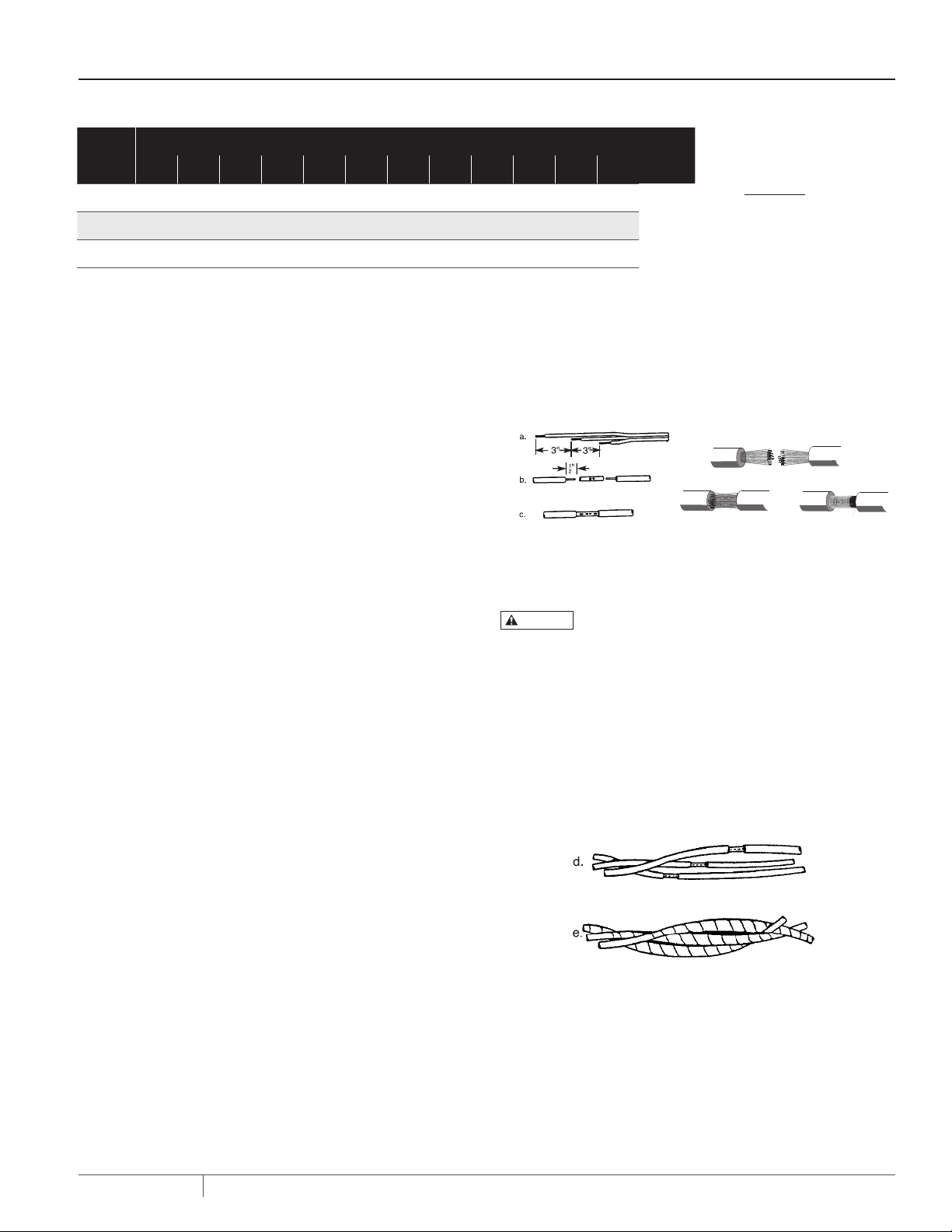
Prepare the cable and make the mechanical connections
(Figure 1A) and splices as follows:
1. Cut motor leads and corresponding cable ends at 3-inch
spacings to stagger connections for a smooth splice.
2. Cut connecting cable to match the motor leads.
NOTICE: Match color coded wires, red to red, black to
black, and white to white.
3. When using a butt connector, expose bare wire for about
1/2”. When using stranded wire, expose about 1” of wire.
NOTICE: Butt connectors may be used with solid wires
through 8 AWG, or stranded wires through 10 AWG.
4. Clean exposed ends of wire thoroughly with emery cloth
or sandpaper to assure good electrical connections.
5A. BUTT CONNECTORS (Figure 1A): Insert wires into con nector
until insulation butts up against connector. Crimp connector
to wires with a pair of crimping pliers. Pull on cable to make
sure the connection is solid and tight.
5B. SOLDERED CONNECTIONS (Figure 1A):
NOTICE: Do not use acid core solder or corrosive solder paste.
6. Repeat Step 5 for each lead.
Figure 1A: C able Splic ing: Solid Wire, Stranded Wire
7. Taping splice (Figure 1B):
CAUTION
never use friction tape on a water-tight splice. Use Scotch
Number 33, or equivalent.
7A. Clean joints and adjoining cable/wire insulation of all
grease and dirt, and build up joint area with tape until it
matches diameter of cable.
7B. Starting 1-1/2” back from the joint, firmly apply one layer
of tape, overlapping about half the previous lap and
continuing approximately 1-1/2” beyond joint. Cut tape
evenly and press both ends firmly against cable.
Because friction tape is not water resistant,
I. Straighten individual cable strands and spread apart
slightly.
II. Clean each strand and push strands of cable into matching
(color-coded) open strands of the motor leads.
III. Wrap entire length of joint with fine copper wire until
strands are compressed.
IV. Apply heat and solder. Solder will follow the heat; make sure
solder flows throughout the joint. Pull firmly on cable to
test joint.
PN524 (08-01-20)
Figure 1B: St agger Splices and Tape
7C. Apply two additional layers of tape, as described in Step 7B,
beginning and ending 1-1/2” beyond the previous starting/
ending points.
5
Page 6

INSTALLATION
Figure 1C: Sp lice and Cable Continuity
SPLICE AND CABLE CONTINUITY TEST
Before installing pump check cable and splices as follows
(see Figure 1C):
1. Submerge cable and splice in steel barrel filled with water.
Make sure both ends of cable are out of water.
2. Clip one ohmmeter lead to barrel. Test each lead in cable
successively by connecting the other ohmmeter lead to the
three cable leads, one after the other.
3. If resistance reading goes to zero on any cable lead, a
leak to ground is present. Pull splice out of water. If meter
reading changes to “infinity ” (no reading) the leak is in the
splice.
4. If leak is not in splice, slowly pull cable out of water until
reading changes to “infinity”. Reading will change to
“infinity” when leak comes out of water.
5. Repair cable by splicing as explained under “Electrical
Splices and Connections”.
ROTATION CHECK (3-PHASE ONLY)
After satisfactorily completing continuity test, connect cable
to pump controller. Check 3-phase motors for correct rotation.
If necessary, reverse any two cable leads at the controller
and recheck rotation. Permanently mark and match to control
box terminals for future reference. Connect cable to motor
controller and then wire controller to disconnect switch.
Connect temporary jumper wire between proper terminals in
controller to temporarily energize magnetic coil.
Momentarily engage disconnect switch and note direction of
rotation. The shaft should rotate counterclockwise when viewed
from the top or shaft end of the motor. If rotation is incorrect,
reverse any two wires; mark wires to correspond with the
controller terminal numbers.
NOTICE: Pump is water lubricated. Do not operate the pump for
more than 5 seconds while it is out of water.
GENERAL INSTALLATION
After completing all connections and tests so far, connect a
5-foot length of pipe to pump.
Lower pump into well with pipe clamps attached to the 5-foot
pipe. Attach a standard length of pipe to 5-foot length and lower
pump CAREFULLY into well.
NOTICE: Do not use a pipe longer than 5 feet for the first
con nection. Hoisting pump upright with a long length of pipe can
cause pump misalignment from excessive leverage.
CAUTION
to avoid damage to cable insulation.
Anchor power cable to pipe ever y 20 feet with adjustable steel
band clamps. Protect insulation from clamps with pieces of split
rubber hose inserted between clamps and cable. Attach cable to
pipe halfway between clamps with waterproof tape (Scotch No.
33 or equivalent).
Use extreme care when lowering pump and cable
SUBMERGENCE
Be sure the pump is always submerged, even at extreme
pumping rates. Install pump at least 10 to 20 feet below the
lowest “drawdown” water level and at least 5 feet above bottom
of well.
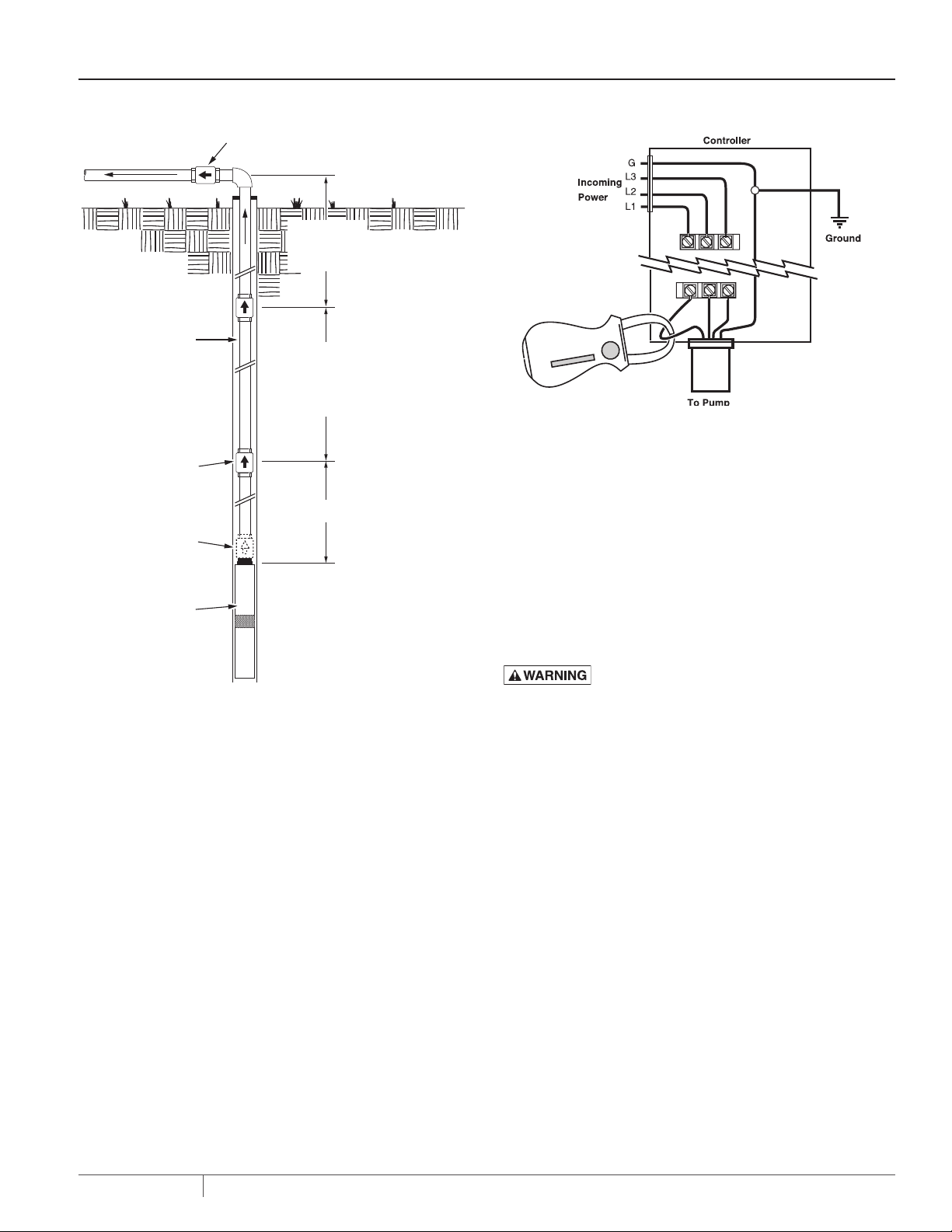
CHECK VALVES
Pump back spin and hydraulic shock can cause severe damage
to the pump and motor. Install at least one check valve in the
discharge pipe (riser pipe) to help prevent this.
Install the first check valve in the pump discharge or in the
discharge pipe it self, not more than 25’ above the pump. Install
another check valve not more than 200 feet above the first one.
Repeat, all the way up the riser pipe. The last check valve on the
6
PN524 (08-01-20)
Page 7
INSTALLATION
Check Valve at surface
To Service
200' Max
Top Check
To Surface
Not
to
Riser Pipe
Install Check
Valves Every 200'
For Full Length
of Riser Pipe
1st. Check Valve
not more than
25 Ft. above pump
OR
25' Max
1st. Check Valve
mounted directly
on pump
Submersible
Pump
To avoid water hammer and
pipe or pump damage,
DO NOT install a check valve
half-way between the pump
and ground level.
Figure 2: Che ck Valve Location
riser pipe should be not more than 200’ below the sur face. Finally,
install a check valve near the well head in the horizontal pipe at
the sur face (see Figure 2).
NOTICE: To avoid water hammer and pipe breakage, do not put a
check valve exactly half-way up the riser pipe (that is, with equal
distance down to the pump and up to the surface), especially if it
is the only check valve in the riser pipe after the pump discharge
check. The ‘equal distance’ in both legs of the pipe can allow
resonations from water hammer which can blow the pump off the
riser pipe.
Scale
Figure 4: Load Current Test
NOTICE: If sand is present in discharge, allow pump to run with
discharge completely open until water is clear. If loud rattling
noises develop, pump is probably cavitating. Gradually close
discharge valve until rattling stops.
INSTALLATION - ELECTRICAL TESTS
Risk of high voltage electrical shock when
testing. Can stun, burn, or kill.
Only qualified electricians should perform these tests. When
testing, use all normal precautions for the voltages involved.
ELECTRICAL TEST OF MOTOR, CABLE, CONNECTIONS
The cable and splices can be damaged as the pump is lowered into
the well. To electrically test them, attach one lead of ohmmeter
to pipe. Attach other lead to each cable lead in tur n. See motor
owner ’s manual for required resistance in a good motor. A low
reading indic ates that cable or splic e has developed a leak to
ground. Remove pump from well and correct problem before
proceeding with installation.
WELL AND PUMP TEST
Check and record static water level of well before starting tests.
Before making final piping connections, test flow rate, capacity,
and condition of well.
NOTICE: Do not operate pump with discharge valve closed.
Operate pump only within pressure and flow limits of operating
range established by performance curve.
PN524 (08-01-20)
7
Page 8

INSTALLATION
Figure 3: Volta ge Test
Measure electrical resistance between motor leads and well
casing when motor is cold.
VOLTAGE TEST (FIGURE 3)
Low or high voltages can cause motor failure. While pump is
operating, check voltage across each pair of leads at motor
controller. Readings more than 10% above or below rated
nameplate voltage can damage pump; correct before placing
pump in service. Test as follows:
1. Disconnect main power supply and open controller.
2. Connect power and start pump. For 3-phase motors, read
voltage across three pairs of leads (L1 – L3, L3 – L2, L2 – L1)
while pump is operating. For single phase motors, read
voltage across L1 and L 2 while pump is operating. Voltage
should be within ±10% of motor nameplate rated voltage. If
not, consult power company.
LOAD CURRENT TEST (FIGURE 4)
Load current should be obtained on each motor lead at the
controller. Partially close pump dis charge valve (keep pressure
and flow within specified operating range) until maximum
amp reading has been obtained. Compare reading with motor
nameplate rating. If reading is 15% or more over rated load,
check for incorrect voltage in supply line or overload due to
abrasives in pump. Find and correct problem before putting
pump in service.
CURRENT UNBALANCE EXAMPLE AND WORKSHEET
3-Ph ase Current Unba lance - Exa mple
Here is an example of current readings at maximum pump loads
on each leg of a three wire hookup. Make cal cu lations for all three
possible hookups.
A. For each hookup, add the readings for the three legs:
Ex.: Hookup #1 Hookup #2 Hookup #3
L1 = 51Amps L1 = 50 Amps L1 = 50 Amps
L2 = 46 Amps L2 = 48 Amps L2 = 49 Amps
L3 = 53 Amps L3 = 52 Amps L3 = 51 Amps
Total 150 AmpsTotal 150 AmpsTotal 150 Amps
B. Divide each total by three to get average amps:
Example: 150/3 = 50
Example: 150/3 = 50
Example: 150/3 = 50
C. Foreachhookup,ndcurrentvaluefarthestfromaverage
(Calculate the greatest current difference from the average).
Ex. #1 Ex. #2 Ex. #3
50 Amps 50 Amps 50 Amps
–46 Amps –48 Amps –49 Amps
= 4 Amps = 2 Amps = 1 Amps
D. Divide this dif ference by the average and multiply by 100 to obtain
the percentage of unbalance. Example:
Ex. 1: 4/50 = .08 x 100 = 8%
Ex. 2: 2/50 = .04 x 100 = 4%
Ex. 3: 1/50 = .02 x 100 = 2%
Use smallest percentage unbalance, in this case Ex. 3.
3-Phase Current Unbalance - Worksheet
Use this worksheet to calculate curent unbalance for your
installation.
A. Add the readings for the three legs:
Ex.: Hookup #1Hookup #2:Hookup #3
L1 = AmpsL1 = AmpsL1 = Amps
L2 = AmpsL2 = AmpsL 2 = Amps
L3 = AmpsL3 = AmpsL3 = Amps
Total Amps Total AmpsTotal Amps
B. Divide each total by three to get average amps:
Hookup #1: /3 =
Hookup #2: /3 =
Hookup #3: /3 =
C. Foreachhookup,ndcurrentvaluefarthestfromaverage
(Calculate the greatest current difference from the average).
Hookup #1 Hookup #2 Hookup #3
Amps Amps Amps
Amps Amps Amps
Amps Amps Amps
D. Divide this dif ference by the average to obtain the
percentage of unbalance:
Hookup #1: / = x100 = %
Hookup #2: / = x100 = %
Hookup #3: / = x100 = %
Use hookup with smallest percentage unbalance.
8
PN524 (08-01-20)
Page 9

SERVICE
INLET SHAFT
SPACER
SERIES
115 3.73 8 (89.30) 1.356 (34.44) 2.8 96 (73.56) 4.37 (111.00) 0.620 (15.74) 1.749 (44.40)
155 3.687 (93.65) 1.407 (35.74) 2.845 (72.28) 4.37 (111.00) 0.671 (17.04) 1.749 (4 4.40)
230 3.789 (96.24) 1.295 (32.90) 2.957 (75.10) 4.37 (111.00) 0.577 (14.66) 1.749 (4 4.40)
300 3.967 (100.75) 0.860 (21.85) 3.3917 (86.15) 4.37 (111.00) 0.400 (10.16) 1.749 (4 4.40)
(See Exp loded View, Page 14)
KEY NO. 19
Table VI: 6TS-Mixed Flow Shaf t Spacer and Bearing Journal Lengths in Inches (mm)
GENERAL SERVICE
When installed in a clear well and operated under normal
conditions, the submersible turbine pump requires no special
maintenance. The hermetically sealed motor is pre-filled and
self-lubricating. Completely tested at the factor y, it should
provide many years of dependable ser vice. The motor is a
THRUST SHAFT
SPACER
KEY NO. 15
DISTANCE SLEEVE
KEY NO. 10
CLEANING SANDLOCKED PUMP
1. Insert a reducing bushing in discharge adapter cap to
receive a hose coupling.
2. Use a hose to flush pump backwards (discharge to suction).
Oscillate shaft backwards and forwards with a pump pliers
and backwash pump for several minutes.
continuous duty type and can operate continuously for long
periods.
CHECKING PUMP PERFORMANCE
Water containing abrasives can cause impeller wear and reduce
REMOVING PUMP FROM WELL
Most pump problems are caused by above-ground elec trical
problems. Minor control box components or outside electrical
difficulties (such as low voltage) can cause a mal function.
Before removing pump from well, check motor windings for
impeller efficiency, resulting in overload conditions. In such
cases, it is necessary to remove the pump from the well and
replace the impellers to maintain capacity and pressure. To
assure quality and integrity of the unit, have your pump serviced
by authorized Berkeley personnel.
damage (check winding resistance with an ohmmeter – see
Page 7). Eliminate all above-ground trouble causes before
pulling pump. Pull the pump only as a last resort.
STAGE SPACER
KEY NO. 10
DISCH. SHAFT
SPACER KEY NO. 7
BEARING
JOURNAL
KEY NO. 6
SANDLOCKED PUMP
NOTICE: Before pulling pump, make all possible above ground
electrical tests. Most submersible pump problems are above
ground, not in the pump itself.
NOTICE: Motor failure can result from starting a sand locked
pump. Do not bypass overload circuit or exceed electrical
rating when tr ying to start a siezed pump.
Remove a sandlocked pump from well for cleaning. To prevent
pump from locking again when reinstalled, clean the well
thoroughly before reinstalling the pump.
PN524 (08-01-20)
9
Page 10
SERVICE
ELECTRICAL TEST
The following electrical checks can be made with pump
installed.
WARNING
testing. Can stun, burn, or kill. 0nly qualified electricians
should perform these tests.When testing, use all normal
precautions for the voltages involved.
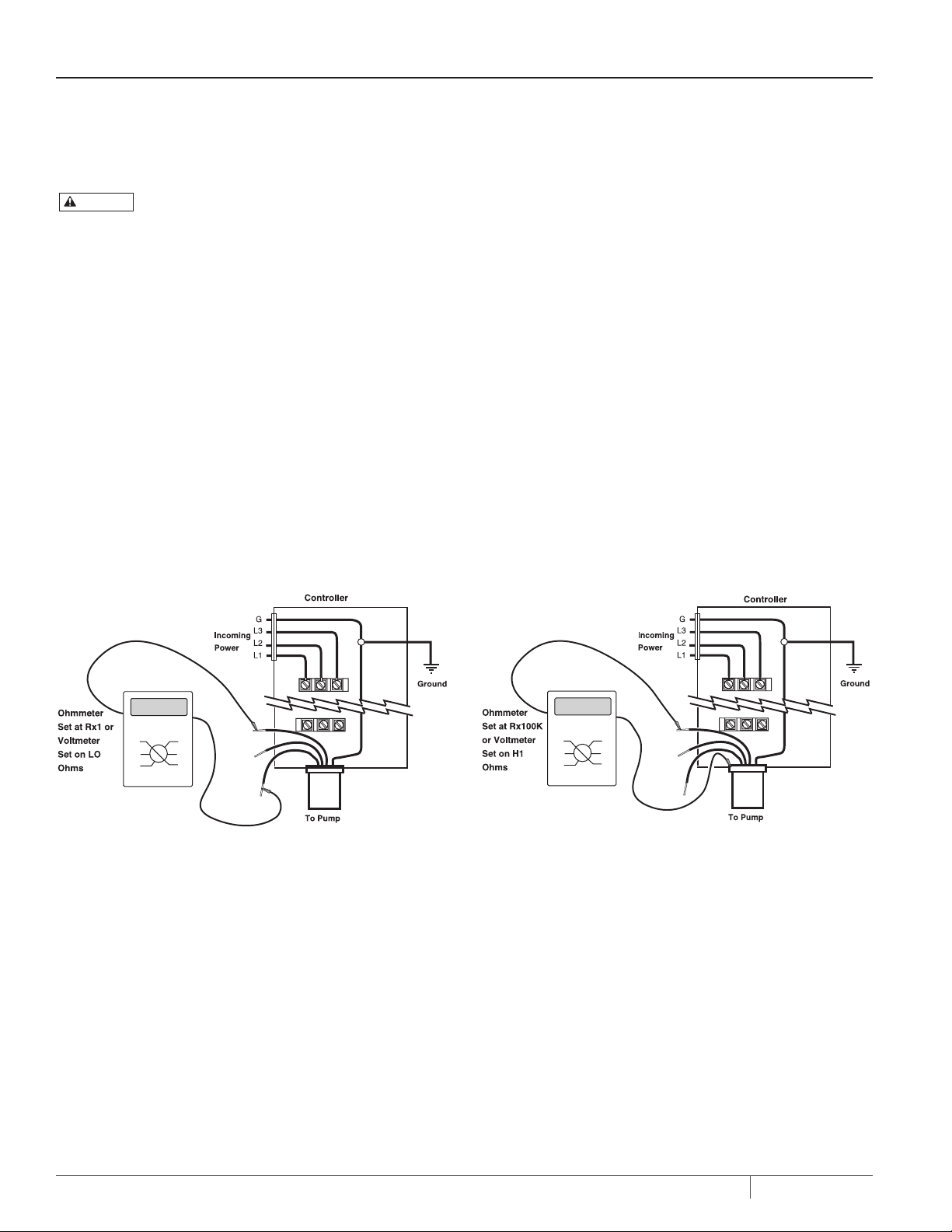
CIRCUIT (WINDING) RESISTANCE TEST ( FIGURE 5)
1. Shut off main power supply and disconnect motor wires.
2. Attach two ohmmeter leads to pairs of cable wires in turn
(black and red wires on three wire single phase units).
Compare readings with data provided in motor manual.
3. If reading is considerably higher than chart, an open circuit
(broken wire) is indicated; if reading is con siderably lower, a
short circuit is indicated. In either case, remove pump from
well and repair unit.
NOTICE: Be sure to include cable and winding resistance.
Multiply cable length by the per-foot cable resistance (see
Table IV, Page 2) and add winding resistance from motor
chart to get total.
Risk of high voltage electrical shock when
GROUND CHECK (FIGURE 6)
1. Shut off main power supply and disconnect motor wires.
2. Attach one ohmmeter lead to pipe or METAL well casing and
the other lead, in turn, to each individual motor wire.
3. If resistance reading goes to zero after touching any of the
wires, the pump should be raised to determine location of
ground fault (cable, motor, or splice).
4. Raise pump, watching resistance reading. When re sis tance
goes to infinity, fault has come out of the water. If ground
fault is located in cable or splice, repair it.
5. If ground fault appears to be located in motor, remove pump
from well. Cut cable at motor side of splice and determine
whether or not motor is grounded. If motor indicates complete
ground (resistance reading goes to zero) replace unit.
If motor is not grounded, re-check splice and cable.
10
Figure 5: Circuit (W inding) Resista nce Test
Figure 6: Ground Check
PN524 (08-01-20)
Page 11
SERVICE
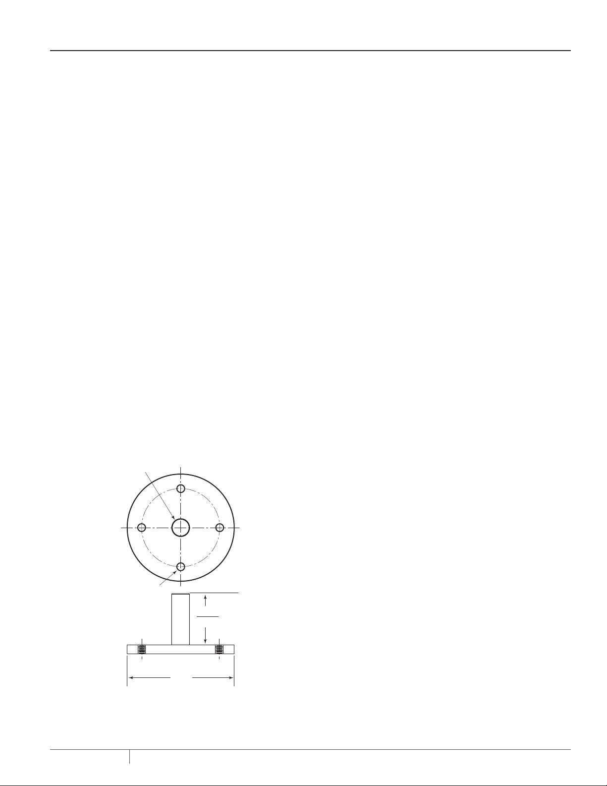
1/2 - 20 UNF-2B
4.38" DIA. B.C.
4 Holes
1.00" Dia.
2542 0796 CH
DISASSEMBLY – MIXED FLOW
Please refer to the exploded view on Page 14 for Key No.
references.
NOTICE: Do not use any sharp tools that could damage parts.
Only gentle tapping with a rubber mallet needs to be applied to
release parts.
1. Remove the Cable Guard (Key No. 23) and the Suction and
2. Loosen and remove the four M12 bolts and washers (Key
3. Gently tap the Discharge (Key No. 1) and remove it.
4. Remove the check valve poppet and the top bowl (Key Nos.
5. Loosen the Rotor Compression Screw (Key No. 4) in the top
6. Remove the Rotor Compression Washer, Bearing Journal,
7. Tap the remaining Bowls (Key No. 9) with a rubber mallet to
8. When you get to the bottom stage, remove the Stainless
9. Finally, remove the coupling from the Pump Shaft.
Coupling Strainers (Key Nos. 24 and 26).
Nos. 18 and 17) and remove the straps.
2 and 3).
of the Shaft (Key No. 27) and remove it.
and Discharge Shaft Spacer (Key Nos. 5,6, and 7) from the
Shaft.
loosen them. Slide the Bowls, Impellers, and Stage Spacers
(Key Nos. 8, 9 and 10) off the Shaft.
Washer, Fiber Washer, Thrust Washer, Distance Sleeve,
Thrust Spacer, Impeller, First Stage Adapter, and Inlet Shaft
Spacer from the Shaft (Key Nos. 12, 13, 14, 11, 15, 8, 20, and 19).
2.875"
2.869"
AS SEM BLY
Please refer to the exploded view on Page 14 for Key No.
references.
1. Clean and straighten the Pump Shaft (Key No. 27) until TIR is
50 to 100 microns (.002” to .004”).
2. Slide the Coupling (Key No. 28) onto the Pump Shaft until
the end of the shaft aligns with the end of the hex portion of
the coupling. Lock the Coupling to the Pump Shaft with two
Allen Screws (Key No. 29).
3. Install the Shaft in the Suction Bracket.
4. Bolt the Suction Bracket and shaft onto the Assembly
Fixture (See Figure 7 for Fixture spec ifications). Make sure
that the Shaft Assembly is correctly aligned and is down
solidly on the Fixture.
5. Install the First Stage Adapter (Key No. 20) on the Suction
Bracket.
6. Slide the Inlet Shaft Spacer (Key No. 19) down over the Shaft
and seat it on the Coupling.
7. Slide an Impeller (Key No. 8) over the Shaft until it rests
on the Inlet Shaft Spacer. Follow it with the Thrust Shaft
Spacer,Thrust Washer, Distance Sleeve, Fiber Washer,
and Stainless Washer (Key Nos. 15, 14, 11, 13, and 12), in that
or der.
8. Slide the first stage Bowl (Key No. 9) down over the Shaft
and seat it on the Suction Adapter.
9. Check the axial clearance of the pump shaft (2.5 to
3 mm or 3/32 to 1/8”).
10. Slide an Impeller (Key No. 8) over the Shaft until it rests on
the Distance Sleeve. Follow it with a Stage Spacer (Key No.
10).
11. Slide the next Bowl over the Shaft and seat it by gently
tapping it with a rubber mallet.
12. Slide an Impeller over the Shaft until it rests on the Stage
Spacer. Follow it with another Stage Spacer.
13. Repeat steps 8, 10, 11 and 12, until you have installed all the
intermediate stages. You do not need to repeat the axial
clearance check at every stage.
14. Slide the last Impeller over the Shaft until it rests on the
Stage Spacer. Follow it with the Discharge Shaft Spacer
and the Bearing Journal (Key Nos. 7 and 6) .
PN524 (08-01-20)
6.0"
Figure 8: Assembly fix ture dimen sions for 6” m otor;
stickup is motor heig ht
11
Page 12

SERVICE
15. Put the Rotor Compression Washer (Key No. 5) on the
Discharge Spacer and lock it with the Rotor Compression
Capscrew (Key No. 4).
NOTE: Use Loctite Threadlocker® on the capscrew threads.
16. Slide the Top Bowl over the shaft and seat it.
17. Install the Check Valve Poppet on top of the last Bowl.
18. Install the Discharge (Key No. 1) on the Top Bowl and seat
the assembly by gently tapping it with a rubber mallet. Be
sure that the strap slots in the discharge are clean.
19. Hook the four Straps (Key No. 21) into the Discharge and
loosely fasten them to the Suction Bracket Assembly with
Lock Washers (Key No. 17), Hex Head Bolts (Key No. 18), and
Strap Nuts (Key No. 16).
PREVENTIVE MAINTENANCE
To avoid major repairs, make the checks listed below every 4 to 6 months.
Tes t
Result Should Be
20. Tighten the four Straps evenly to 45 ft.-lbs. torque. Be sure
that the Straps seat completely in the discharge.
21. Check the axial clearance of the pump shaft (2.5 to
3 mm. or 3/32 to 1/8”).
22. Check for free rotation of the pump stack.
23. Install the Suction Strainer (Key No. 24).
24. Install the Cable Guard Clamps and Cable Guard (Key Nos. 22
and 23) on the pump.
25. Remove the pump from the fixture, install the Coupling
Screen (Key No. 26), and mount the pump on the motor.
The pump is ready for installation.
Possible Indications
1. Measure and record the standing
water level (from top of well casing).
2. Measure electrical resistance
between motor leads and well
casing with motor
cold.
3. Check pump flow capacity (gallons
per minute).
4. Check pump discharge pressure
(PSI) at operating conditions.
5. Check drawdown level (in feet) from
standing water level.
6. Measure voltage across motor
leadsn while pump is operating.
1. Reference number.
2. See motor manual.
3. At least 90% of readings at
installation.
4. At least 90% of readings at
installation.
5. High enough so that pump does not
break suction.
6. Within ±10% of rated voltage.
1. To aid in monitoring pump
performance.
2. See motor manual.
3. Lower readings may indicate pump
needs repair.
4. Lower reading indicates pump
wear, increased friction losses, or
change in standing water level in
well.
5. Cavitation can damage pump;
increased drawdown may indicate
reduced well flow.
6. If voltage is more than 110% or less
than 90% of rated voltage, consult
power company.
12
PN524 (08-01-20)
Page 13
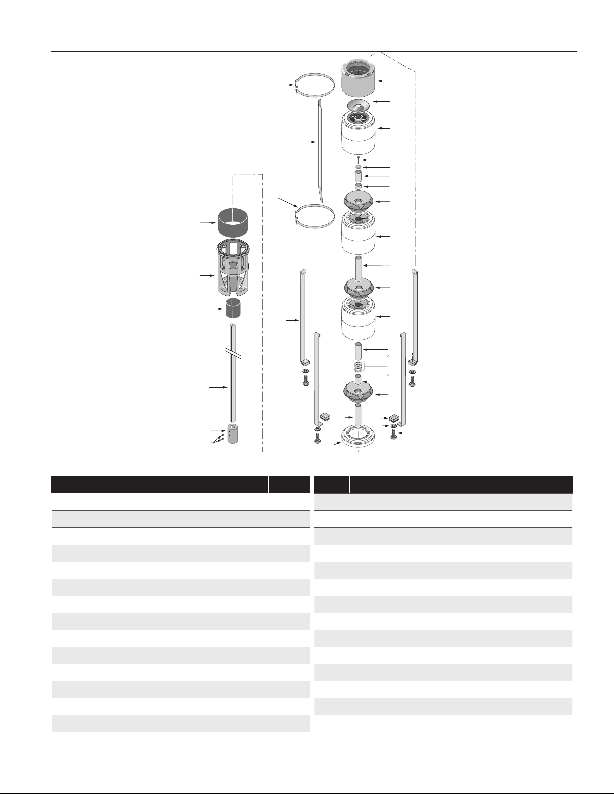
REPEAIR PARTS LIST
24
25
26
22
1
2
3
23
4
5
6
7
22
8
9
10
8
21
9
11
12
13
14
27
15
8
28
29
6TS-115, 6TS-155, 6TS-230 and 6 TS-300 Se ries - Mixed Flow Submersible Turbine Pumps
KEY DESCRIPTION QT Y.
1 Discharge 1
2 Che ck Valve Poppet 1
3 Top Bow l 1
4 Stack Compression Capscrew 1
5 Stack Compression Washer 1
6 Bearing Journal 1
7 Dishcharge Shaft Spacer 1
8 Impeller *
9 Bowl w/ Diffuser *
10 Stage Spacer *
11 Distance Sleeve 1
12 Stainless Washer 1
13 Fiber Washer 1
19
16
17
18
20
KEY DESCRIPTION QT Y.
16 St rap Nut 4
17 Lock Washer 4
18 Strap Capscrew 4
19 Inlet Shaf t Spacer 1
20 Fi rst Stag e Adapter 1
21 Strap 4
22 Cable Guard Bracket 2
23 Cable Guard 1
24 Suction Screen 1
25 Suction Bracket 1
26 Coupling Guard 1
27 Shaft 1
28 Coupling 1
14 Thrus t Washer 1
15 Thrust Shaft Spacer 1
PN524 (08-01-20)
29 Coupling Set Screws 2
*Qu antit y determin ed by numb er of stag es,
13
Page 14

TROUBLESHOOTING
WARNING
Hazardous voltage. Can shock, burn, or kill.
When troubleshooting or servicing pump, use all normal
precautions for the voltages involved.
PROBLEM POSSIBLE CAUSE REMEDY
1. Pump sandlocked.
Fuses blow or overload
circuit breaker trips when
motor starts:
Fuses blow or overload
trips while motor is running:
Motor does not start but does not
blow fuses or trip circuit breaker:
Pump does not shut off: 1. Cable leads improperly connected. 1. Check wiring diagram on box cover for correct
Motor runs, but delivers
little or no water:
2. Low or high voltage.
3. Cable damaged or shorted.
4. Pump forced into crooked well.
1. Low or high voltage.
2. Water contains abrasives.
3. Motor or cable shorted and/or
grounded.
1. Fuses blown or circuit breaker tripped.
2. Voltage does not reach terminals.
3. Loose wire in control box.
4. Defective magnetic controller coil.
1. Horizontal line check valve installed
backwards.
2. Motor running backwards
(3-Phase only).
3. Pump gaslocked.
4. Water level in well has dropped.
5. Leak in discharge pipe.
6. Coupling between motor shaft
and pump shaft broken.
7. Pump parts worn from abrasives.
8. Intake screen clogged.
9. Pump set below recommended
depth.
10.Discharge pipe friction reduces
output.
1. Disconnect power unless required for testing.
2. Have electrical testing done by a qualified electrician.
3. Most problems occur above ground. Remove pump from
well only as a last resort.
1. a) Check motor winding resistance - see
“Circuit (Winding) Resistance”, Page 6.
b) If motor is not shorted, turn on current
and rap discharge pipe sharply to loosen sand.
c) Pull pump and clean.
2. Check line voltage (see Page 4). If high or low, contact
power company.
3. Check pump cable for ground (see Page 6).
4. Forcing pump into a crooked hole will cause
misalignment of pump and motor. Consult well driller.
1. Check voltage on service lines (see Page 4).
2. If water contains excessive sand, remove pump and
clean sand out of well.
3. See “Circuit (Winding) Resistance Test” and “Ground
Check”, Page 6.
1. Reset circuit breakers or replace fuses.
2. 3-Phase: Check voltage at controller between wire
pairs: L1 – L3, L3 – L2, L2 – L1.
Single Phase: Check voltage between L1 and L 2 on
box terminal strip.
3. Check and tighten all wires.
4. Check starter and coil.
connections.
1. Reinstall correctly.
2. Reconnect motor for proper rotation (see Page 3).
3. Star t and stop pump several times allowing one
minute between stops and starts.
4.a) Restrictpumpowtoequalwellproduction.
b) Installliquidlevelcontrol.
c) Reset pump lower in well.
5. Raise pipe until leak is found.
6. Remove pump from well and check coupling.
If broken, call Berkeley Pumps.
7. a) Check pump shut-off pressure. Pressure should
be at least 90% of pressure at installation.
b) Call Berkeley Pumps.
8. Remove pump from well and clean screen.
9. a) Reduce pressure switch setting until pump will
shut off.
b) Install pump producing higher pressure.
10. Install larger pipe or pump producing higher pressure.
PN524 (08-01-20)
14
Page 15

Warranty
RESPECT TO THE PRODUCTS, INCLUDING, BUT NOT TO ANY WARRANTIES OF MERCHANTABILITY OR WARRANTY OF FITNESS FOR
Pentair BERKELEY® warrants to the original consumer purchaser (“Purchaser” or “You”) of the products listed in the table below,
that they will be free from defects in material and workmanship for the Warranty Period shown in the table below.
Product Warranty Period
Water Systems:
Water Systems Products — jet pumps, small centrifugal pumps, submersible pumps and
related accessories
Pentair Pro-Source® Composite Tanks 5 years from date of original installation
Pentair Pro-Source Steel Pressure Tanks 5 years from date of original installation
Pentair Pro-Source Epoxy-Lined Tanks 3 years from date of original installation
Agricultural/Commercial:
Centrifugals – close-coupled motor drive, frame mount, SAE mount, engine drive, VMS, SSCX,
SSHM
Submersible Turbines, 6” diameter and larger
whichever occurs first:
12 months from date of original installation, or
18 months from date of manufacture
12 months from date of original installation, or
24 months from date of manufacture
12 months from date of original installation, or
24 months from date of manufacture
Our warranty will not apply to any product that, in our sole judgement, has been subject to negligence, misapplication, improper
installation, or improper maintenance. Examples that may result in denial of a warranty claim (this list is not all inclusive):
• Damage caused by careless handling, improper repackaging, or shipping.
• Damage due to misapplication, misuse, abuse, or failure to operate equipment as specified in the owner’s manual.
• Damage caused by failure to install products as specified in the owner’s manual.
• Damage due to unauthorized product modifications or failure to use Pentair original replacement parts.
• Damage caused by negligence, or failure to properly maintain products as specified in the owner’s manual.
• Damage caused by water freezing inside the product.
• Accidental damage, fire, acts of God, or other circumstances outside the control of Pentair.
Without limiting the foregoing, operating a three phase motor with single phase power through a phase converter will void the
warranty. Note also that three phase motors must be protected by three-leg, ambient compensated, extra-quick trip overload
relays of the recommended size or the warranty is void.
All impeller diameters specified in the BEC2 pump sizing program have been tested and determined to not exceed the service
factor of the specified motor. Oversized impeller diameters can be requested, however, use of an oversized impeller will void any
warranty claims.
Your only remedy, and BERKELEY’s only duty under this warranty, is that BERKELEY repair or replace defective products (at
BERKELEY’s choice). THE REMEDIES DESCRIBED HERE ARE YOUR SOLE AND EXCLUSIVE REMEDIES AND OUR ENTIRE LIABILITY
FOR ANY BREACH OF THIS WARRANTY.
You must pay all labor and shipping charges associated with the warranty and must request warranty service through the installing
dealer as soon as a problem is discovered. No request for service will be accepted if received after the Warranty Period has
expired. This warranty is not transferable.
BERKELEY’S LIABILITY SHALL UNDER NO CIRCUMSTANCES EXCEED THE ACTUAL AMOUNT PAID BY YOU FOR THE PRODUCT AT
ISSUE. BERKELEY SHALL NOT, UNDER ANY CIRCUMSTANCES, BE LIABLE FOR ANY CONSEQUENTIAL, INCIDENTAL, SPECIAL,
PUNITIVE, OR CONTINGENT DAMAGES OR LOSSES WHATSOEVER, WHETHER DIRECT OR INDIRECT. THE FOREGOING WARRANTY
IS EXCLUSIVE. EXCEPT FOR THE WARRANTY SET FORTH HEREIN, BERKELEY MAKES NO WARRANTY WHATSOEVER WITH
A PARTICULAR PURPOSE, WHETHER EXPRESS OR IMPLIED BY LAW, COURSE OF DEALING, COURSE OF PERFORMANCE, USAGE
OF TRADE OR OTHERWISE.
THE FOREGOING WARRANTIES SHALL NOT EXTEND BEYOND THE DURATION PROVIDED HEREIN. Some states do not allow the
exclusion or limitation of incidental or consequential damages or limitations on the duration of an implied warranty, so the above
limitations or exclusions may not apply to You. This warranty gives You specific legal rights and You may also have other rights
which vary from state to state.
This Warranty is effective July 14, 2020 and replaces all undated warranties and warranties dated before July 14, 2020.
BERKELEY
293 Wright Street, Delavan, WI 53115
Phone: 888-237-5353 • Fax: 800-321-8793 • Pentair.com/Berkeley
In Canada: 490 Pinebush Road, Unit 4, Cambridge, Ontario N1T 0A5
Phone: 800-363-7867 • Fax: 888-606-5484
PN524 (08-01-20)
15
Page 16

293 Wright Street | Delavan, WI 53115 | Ph: 888-237-5353 | Orders Fax: 800.321.8793 | pentair.com
All indicated Pentair trademarks and logos are property of Pentair. Third party registered and unregistered trademarks and logos are the property of their respective owners.
Becausewearecontinuouslyimprovingourproductsandservices,Pentairreservestherighttochangespecicationswithoutpriornotice.Pentairisanequalopportunityemployer.
P524 (08-01-2020) ©2020 Pentair. All Rights Reserved.
 Loading...