


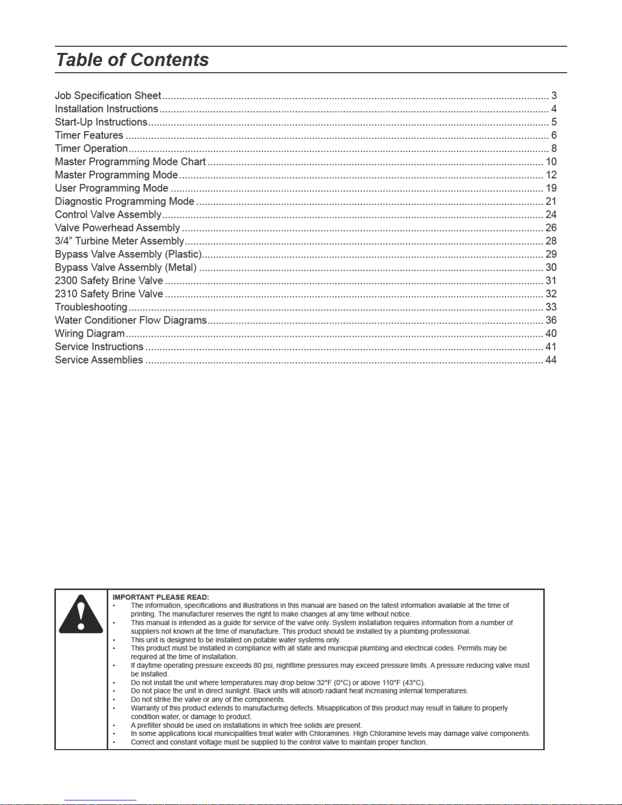

Job Specication Sheet
Job Number: __________________
Model Number: ________________
Water Hardness: ___________________ ppm or gpg
Capacity Per Unit: ______________
Mineral Tank Size: ___________ Diameter: ___________ Height:
Salt Setting per Regeneration: _____________________________________________
1. Type of Timer:
A. 7 Day or 12 Day B. Meter Initiated
2. Meter Size:
A. 3/4” Std Range (125 - 2,100 gallon setting)
B. 3/4” Ext Range (625 - 10,625 gallon setting)
C. 1” Std Range (310 - 5,270 gallon setting)
D. 1” Ext Range (1,150 - 26,350 gallon setting)
E. 1 1/2” Std Range (625 - 10,625 gallon setting)
F. 1 1/2” Ext Range (3,125 - 53,125 gallon setting)
G. 2” Std Range (1,250 - 21,250 gallon setting)
H. 2” Ext Range (6,250 - 106,250 gallon setting)
I. 3” Std Range (3,750 - 63,750 gallon setting)
J. 3” Ext Range (18,750 - 318,750 gallon setting)
K. Electronic
3. System Type:
A. System #4: 1 Tank, 1 Meter, Immediate, or Delayed Regeneration
B. System #4: Time Clock
C. System #4: Twin Tank
D. System #5: 2-5 Tanks, 2 Meters, Interlock
E. System #6: 2-5 Tanks, 1 Meter, Series Regeneration
F. System #7: 2-5 Tanks, 1 Meter, Alternating
G. System #9: Electronic Only, 2-4 Tanks, Meter per Valve, Alternating
H. System #14: Electronic Only, 2-4 Tanks, Meter per Valve. Brings units on and ofine based on ow.
4. Timer Program Settings:
A. Backwash: ____________________ Minutes
B. Brine and Slow Rinse: ___________ Minutes
C. Rapid Rinse: __________________ Minutes
D. Brine Tank Rell: _______________ Minutes
. 5. Drain Line Flow Control: ____________ gpm
. 6. Brine Line Flow Controller: __________________ gpm
. 7. Injector Size#: _____________________
. 8. Piston Type:
A. Hard Water Bypass
B. No Hard Water Bypass
Page 3
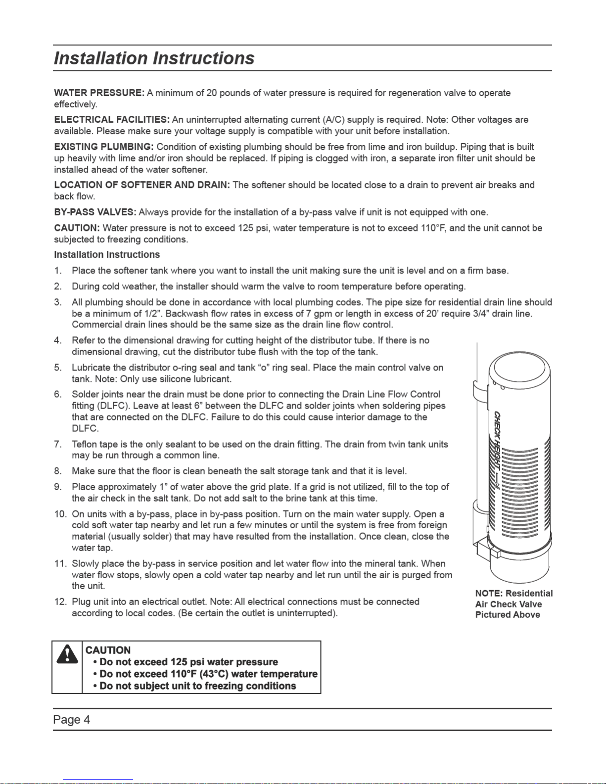

Start-Up Instructions
The water softener should be installed with the inlet, outlet, and drain connections made in accordance with the
manufacturer’s recommendations, and to meet applicable plumbing codes.
Turn the manual regeneraton knob slowly in a clockwise direction until the program micro switch lifts on top of
1.
the rst set of pins. Allow the drive motor to move the piston to the rst regeneration step and stop. Each time
the program switch position changes, the valve will advance to the next regeneration step. Always allow the
motor to stop before moving to the next set of pins or spaces..
NOTE: For electronic valves, please refer to the manual regeneration part of the timer operation
section. If the valve came with a separate electronic timer service manual, refer to the timer operation
section of the electronic timer service manual.
Position the valve to backwash. Ensure the drain line ow remains steady for 10 minutes or until the water
2.
runs clear (see above).
Position the valve to the brine / slow rinse position. Ensure the unit is drawing water from the brine tank (this
3.
step may need to be repeated).
Position the valve to the rapid rinse position. Check the drain line ow, and run for 5 minutes or until the water
4.
runs clear.
Position the valve to the start of the brine tank ll cycle. Ensure water goes into the brine tank at the desired
5.
rate. The brine valve drive cam will hold the valve in this position to ll the brine tank for the rst regeneration.
Replace control box cover.
6.
Put salt in the brine tank..
7.
.
NOTE: Do not use granulated or rock salt.
Page 5
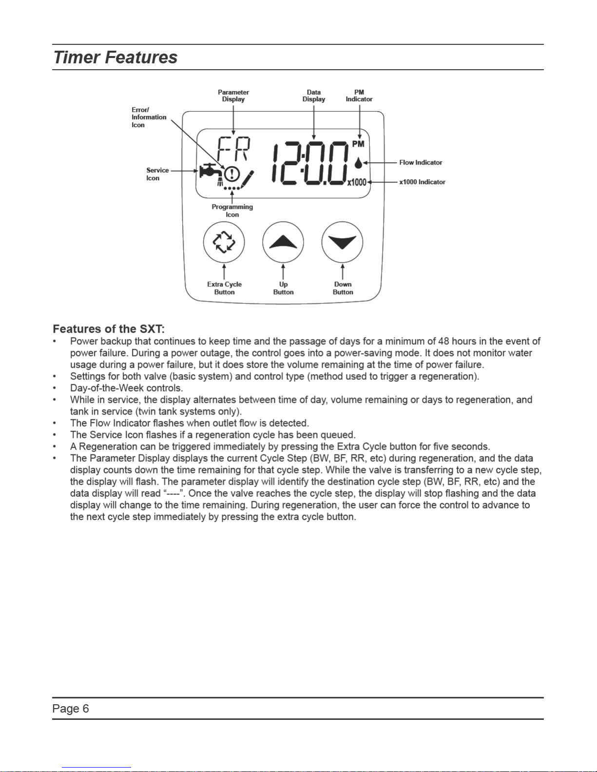

Timer Features
Setting the Time of Day
1.
Press and hold either the Up or Down buttons until the programming icon replaces the service icon and the
parameter display reads TD.
2.
Adjust the displayed time with the Up and Down buttons.
3.
When the desired time is set, press the Extra Cycle button to resume normal operation. The unit will also
return to normal operation after 5 seconds if no buttons are pressed..
.
.
.
.
.
Queueing a Regeneration
1.
Press the Extra Cycle button. The service icon will ash to indicate that a regeneration is queued.
2.
To cancel a queued regeneration, press the Extra Cycle button.
Regenerating Immediately
Press and hold the Extra Cycle button for ve seconds.
Page 7

Timer Operation
Meter Immediate Control
A meter immediate control measures water usage and regenerates the system as soon as the calculated system
capacity is depleted. The control calculates the system capacity by dividing the unit capacity (typically expressed
in grains/unit volume) by the feedwater hardness and subtracting the reserve. Meter Immediate systems generally
do not use a reserve volume. However, in twin tank systems with soft-water regeneration, the reserve capacity
should be set to the volume of water used during regeneration to prevent hard water break-through. A Meter
Immediate control will also start a regeneration cycle at the programmed regeneration time if a number of days
equal to the regeneration day override pass before water usage depletes the calculated system capacity.
Meter Delayed Control
A Meter Delayed Control measures water usage and regenerates the system at the programmed regeneration
time after the calculated system capacity is depleted. As with Meter Immediate systems, the control calculates the
system capacity by dividing the unit capacity by the feedwater hardness and subtracting the reserve. The reserve
should be set to insure that the system delivers treated water between the time the system capacity is depleted
and the actual regeneration time. A Meter Delayed control will also start a regeneration cycle at the programmed
regeneration time if a number of days equal to the regeneration day override pass before water usage depletes
the calculated system capacity.
Time Clock Delayed Control
A Time Clock Delayed Control regenerates the system on a timed interval. The control will initiate a regeneration
cycle at the programmed regeneration time when the number of days since the last regeneration equals the
regeneration day override value.
Day of the Week Control
This control regenerates the system on a weekly schedule. The schedule is dened in Master Programming by
setting each day to either “off” or “on.” The control will initiates a regeneration cycle on days that have been set to
“on” at the specied regeneration time.
Control Operation During Regeneration
During regeneration, the control displays a special regeneration display. In this display, the control shows the
current regeneration step number the valve is advancing to, or has reached, and the time remaining in that step.
The step number that displays ashes until the valve completes driving to this regeneration step position. Once all
regeneration steps are complete the valve returns to service and resumes normal operation.
Pressing the Extra Cycle button during a regeneration cycle immediately advances the valve to the next cycle
step position and resumes normal step timing.
Control Operation During Programming
The control only enters the Program Mode with the valve in service. While in the Program Mode, the control
continues to operate normally monitoring water usage and keeping all displays up to date. Control programming is
stored in memory permanently
, eliminating the need for battery backup power.
Manually Initiating a Regeneration
When timer is in service, press the Extra Cycle button for 5 seconds on the main screen.
1.
The timer advances to Regeneration Cycle Step #1 (backwash), and begins programmed time count down.
2.
Press the Extra Cycle button once to advance valve to Regeneration Cycle Step #2 (brine draw & slow rinse).
3.
Press the Extra Cycle button once to advance valve to Regeneration Cycle Step #3 (rapid rinse).
4.
Press the Extra Cycle button once to advance valve to Regeneration Cycle Step #4 (brine rell).
5.
Press the Extra Cycle button once more to advance the valve back to in service..
6.
NOTE: If the unit is a lter or upow, the cycle step order may change..
NOTE: A queued regeneration can be initiated by pressing the Extra Cycle button. To clear a queued regener-
ation, press the Extra Cycle button again to cancel. If regeneration occurs for any reason prior to the delayed
regeneration time, the manual regeneration request shall be cleared.
Page 8

Timer Operation
Control Operation During A Power Failure
The SXT includes integral power backup. In the event of power failure, the control shifts into a power-saving
mode. The control stops monitoring water usage, and the display and motor shut down, but it continues to keep
track of the time and day for a minimum of 48 hours.
The system conguration settings are stored in a non-volatile memory and are stored indenitely with or without
line power. The Time of Day ashes when there has been a power failure. Press any button to stop the Time of
Day from ashing.
If power fails while the unit is in regeneration, the control will save the current valve position before it shuts down.
When power is restored, the control will resume the regeneration cycle from the point where power failed. Note
that if power fails during a regeneration cycle, the valve will remain in it’s current position until power is restored.
The valve system should include all required safety components to prevent overows resulting from a power
failure during regeneration.
The control will not start a new regeneration cycle without line power. If the valve misses a scheduled
regeneration due to a power failure, it will queue a regeneration. Once power is restored, the control will initiate
a regeneration cycle the next time that the Time of Day equals the programmed regeneration time. Typically,
this means that the valve will regenerate one day after it was originally scheduled. If the treated water output is
important and power interruptions are expected, the system should be setup with a sufcient reserve capacity to
compensate for regeneration delays.
Page 9
Master Programming Mode Chart
Master Programming Options
Abbreviation Parameter Option
Abbreviation
GAL Gallons
DF Display Format
VT Valve Type
CT Control Type
NT Number of Tanks
TS Tank in Service
Ltr Liters
Cu Cubic Meters
St1b Standard Downow/Upow Single Backwash
St2b Standard Downow/Upow Double Backwash
Fltr Filter
UFbF Upow Brine First
Othr Other
Fd Meter (Flow) Delayed
FI Meter (Flow) Immediate
tc Time Clock
dAY Day of Week
1 Single Tank System
2 Two Tank System
U1 Tank 1 in Service
U2 Tank 2 in Service
Options
C Unit Capacity Unit Capacity (Grains)
H
RS Reserve Selection SF Percentage Safety Factor
SF Safety Factor
RC
DO Day Override The system’s day override setting
RT Regen Time The time of day the system will regenerate
BW, BD, RR,
BF
D1, D2, D3, D4,
D5, D6, & D7
CD Current Day The Current day of the week
CAUTION: Before entering Master Programming, please contact your local professional water dealer.
Feedwater
Hardness
rc Fixed Reserve Capacity
Fixed Reserve
Capacity
Regen Cycle Step
Times
Day of Week
Settings
Hardness of Inlet Water
Percentage of the system capacity to be used as a
reserve
Fixed volume to be used as a reserve
The time duration for each regeneration step. Adjust-
able from OFF and 0-199 minutes..
NOTE: If “Othr” is chosen under “Valve Type”, then
R1, R2, R3, etc, will be displayed instead
Regeneration setting (On or OFF) for each day of the
week on day-of-week systems
Page 10
Master Programming Mode Chart
Master Programming Options
t0.7 3/4” Turbine Meter
P0.7 3/4” Paddle Wheel Meter
t1.0 1” Turbine Meter
FM Flow Meter Type
K Meter Pulse Setting Meter pulses per gallon for generic/other ow meter
NOTES:
Some items may not be shown depending on timer conguration.
The timer will discard any changes and exit Master Programming Mode if any button is not pressed for
sixty seconds.
P1.0 1” Paddle Wheel Meter
t1.5 1.5” Turbine Meter
P1.5 1.5” Paddle Wheel Meter
Gen Generic or Other Meter
CAUTION: Before entering Master Programming, please contact your local professional water dealer.
Page 11
Master Programming Mode
When the Master Programming Mode is entered, all available option setting displays may be viewed and set as
needed. Depending on current option settings, some parameters cannot be viewed or set..
.
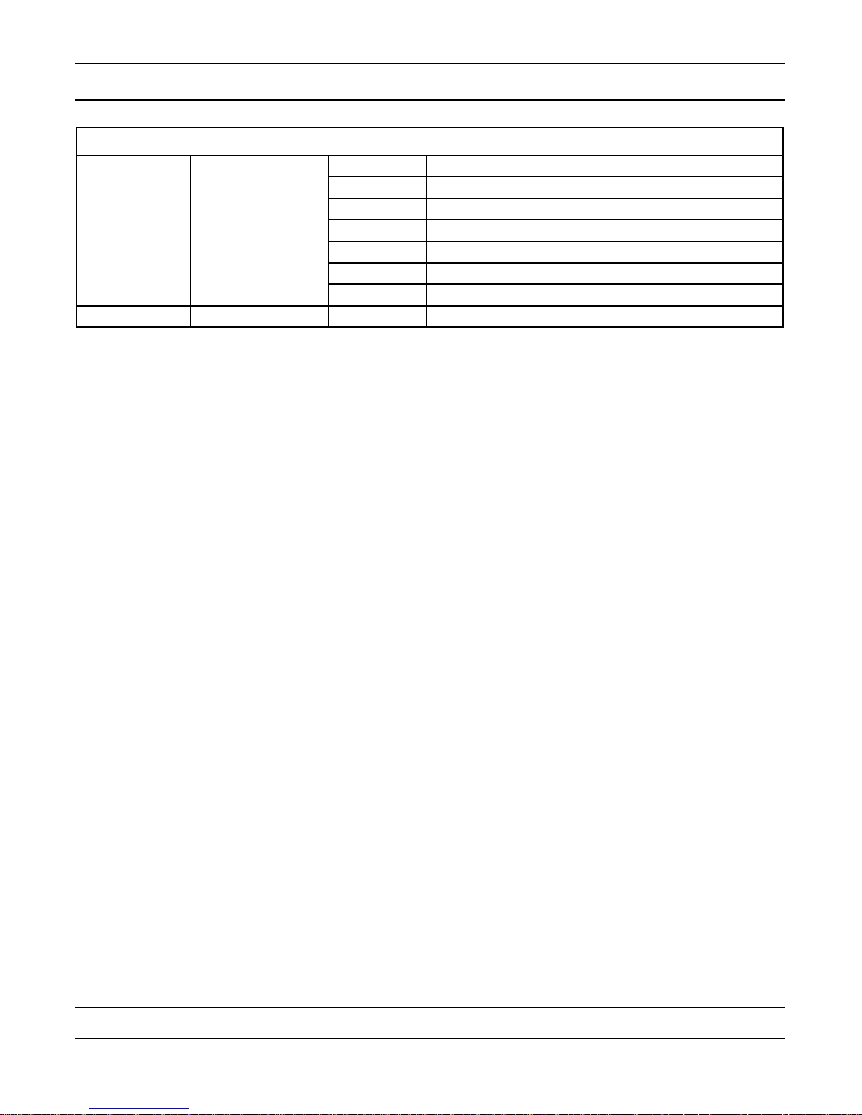
Setting the Time of Day
Press and hold either the Up or Down buttons until the programming icon replaces the service icon and the
1.
parameter display reads TD.
Adjust the displayed time with the Up and Down buttons.
2.
When the desired time is set, press the Extra Cycle button to resume normal operation. The unit will also
3.
return to normal operation after 5 seconds if no buttons are pressed..
.
.
.
.
Entering Master Programming Mode
Set the Time Of Day display to 12:01 P.M. Press the Extra Cycle button (to exit Setting Time of Day mode). Then
press and hold the Up and Down buttons together until the programming icon replaces the service icon and the
Display Format screen appears.
Exiting Master Programming Mode
Press the Extra Cycle button to accept the displayed settings and cycle to the next parameter. Press the
Extra Cycle button at the last parameter to save all settings and return to normal operation. The control
will automatically disregard any programming changes and return to normal operation if it is left in Master
Programming mode for 5 minutes without any keypad input.
Resets:
Soft Reset: Press and hold the Extra Cycle and Down buttons for 25 seconds while in normal Service mode.
This resets all parameters to the system default values, except the volume remaining in meter immediate or meter
delayed systems and days since regeneration in the time clock system.
Master Reset: Hold the Extra Cycle button while powering up the unit. This resets all of the parameters in the
unit. Check and verify the choices selected in Master Programming Mode.
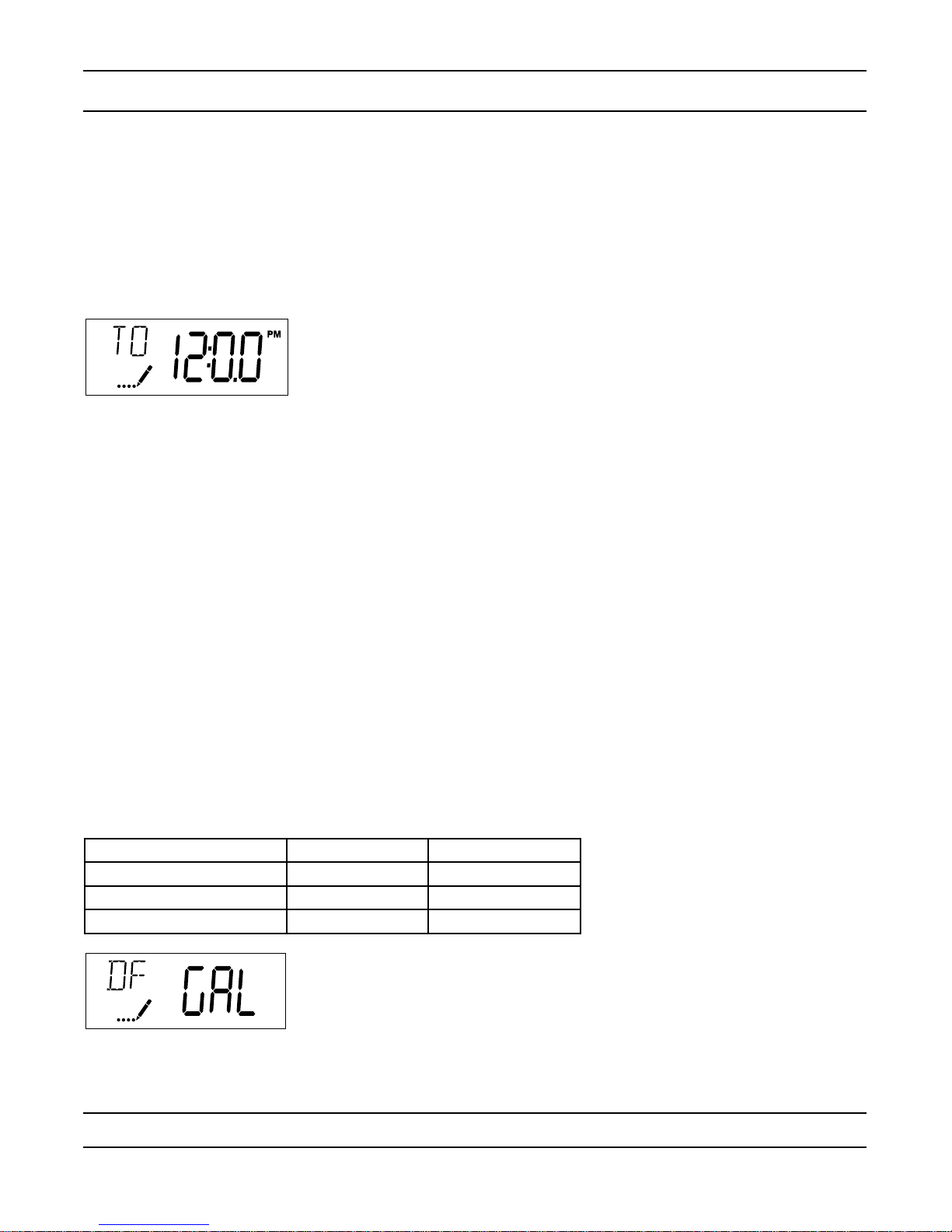
1. Display Format (Display Code DF)
This is the rst screen that appears when entering Master Programming Mode. The Display Format setting
species the unit of measure that will be used for volume and how the control will display the Time of Day. This
option setting is identied by “DF” in the upper left hand corner of the screen. There are three possible settings:
Display Format Setting Unit of Volume Time Display
GAL U.S. Gallons 12-Hour AM/PM
Ltr Liters 24-Hour
Cu Cubic Meters 24-Hour
CAUTION: Before entering Master Programming, please contact your local professional water dealer.
Page 12
Master Programming Mode
2. Valve Type (Display Code VT)
Press the Extra Cycle button. Use this display to set the Valve Type. The Valve Type setting species the type of
cycle that the valve follows during regeneration. Note that some valve types require that the valve be built with
specic subcomponents. Ensure the valve is congured properly before changing the Valve Type setting. This
option setting is identied by “VT” in the upper left hand corner of the screen. There are 5 possible settings:
Abbreviation Parameter
St1b Standard Downow/Upow, Single Backwash
St2b Standard Downow/Upow, Double Backwash
Fltr Filter
UFbF Upow Brine First
Othr Other
.
.
.
.
.
.
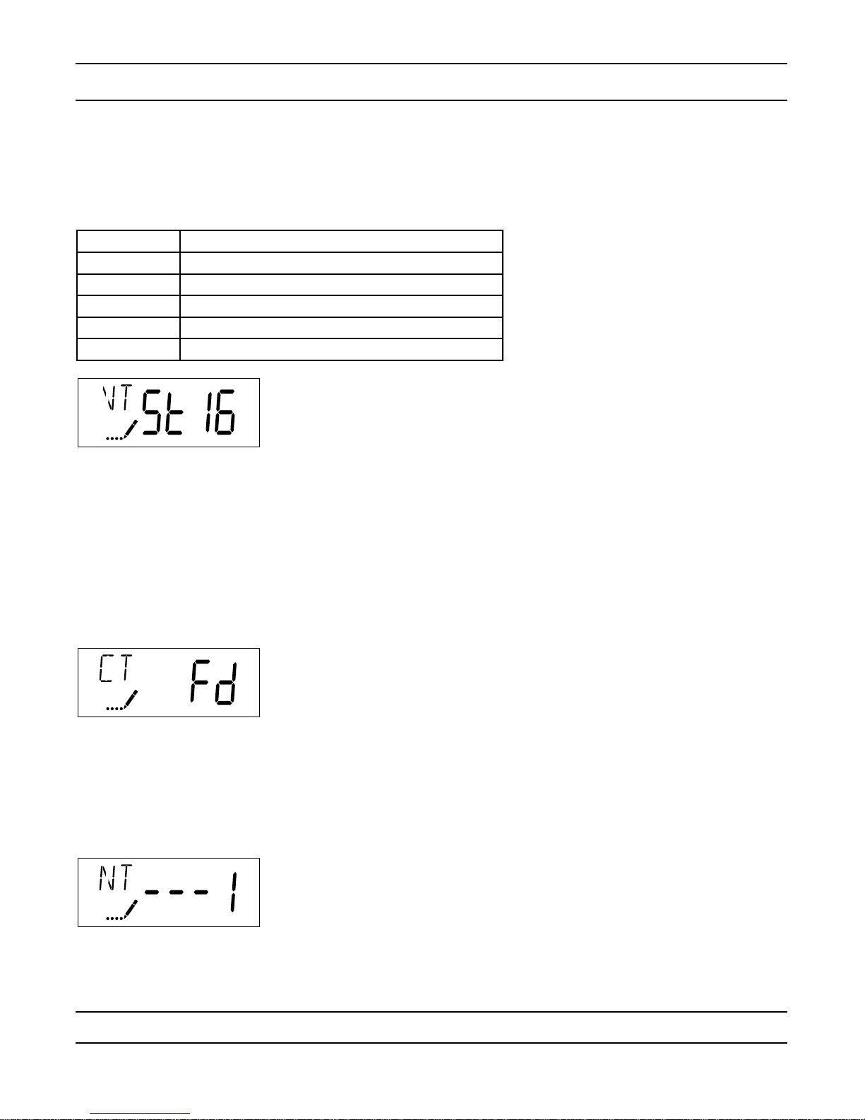
3. Control Type (Display Code CT)
Press the Extra Cycle button. Use this display to set the Control Type. This species how the control determines
when to trigger a regeneration. For details on how the various options function, refer to the “Timer Operation”
section of this service manual. This option setting is identied by “CT” in the upper left hand corner of the screen.
There are four possible settings:
Meter Delayed: Fd
Meter Immediate: FI
Time Clock: tc
Day of Week: dAY
4. Number of Tanks (Display Code NT)
Press the Extra Cycle button. Use this display to set the Number of Tanks in your system. This option setting is
identied by “NT” in the upper left hand corner of the screen. There are two possible settings:
Single Tank System: 1
Two-Tank System: 2
CAUTION: Before entering Master Programming, please contact your local professional water dealer.
Page 13
Master Programming Mode
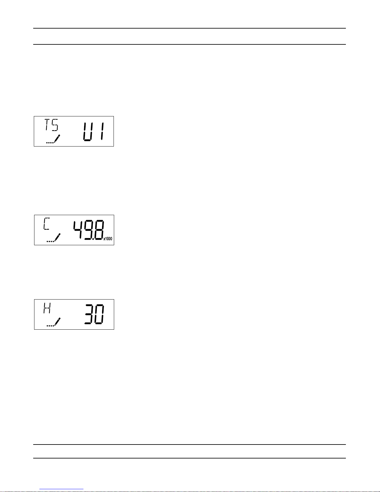
5. Tank in Service (Display Code TS)
Press the Extra Cycle button. Use this display to set whether tank one or tank two is in service. This option setting
is identied by “TS” in the upper left hand corner of the screen. This parameter is only available if the number of
tanks has been set to 2. There are two possible settings:
Tank One in Service: U1
Tank Two in Service: U2
6. Unit Capacity (Display Code C)
Press the Extra Cycle button. Use this display to set the Unit Capacity. This setting species the treatment
capacity of the system media. Enter the capacity of the media bed in grains of hardness when conguring a
softener system, and in the desired volume capacity when conguring a lter system. This option setting is
identied by “C” in the upper left hand corner of the screen. The Unit Capacity parameter is only available if the
control type has been set to one of the metered options. Use the Up and Down buttons to adjust the value as
needed.
7. Feedwater Hardness (Display Code H)
Press the Extra Cycle button. Use this display to set the Feedwater Hardness. Enter the feedwater hardness in
grains per unit volume for softener systems, or 1 for lter systems. This option setting is identied by “H” in the
upper left hand corner of the screen. The feedwater hardness parameter is only available if the control type has
been set to one of the metered options. Use the Up and Down buttons to adjust the value as needed.
CAUTION: Before entering Master Programming, please contact your local professional water dealer.
Page 14
Master Programming Mode
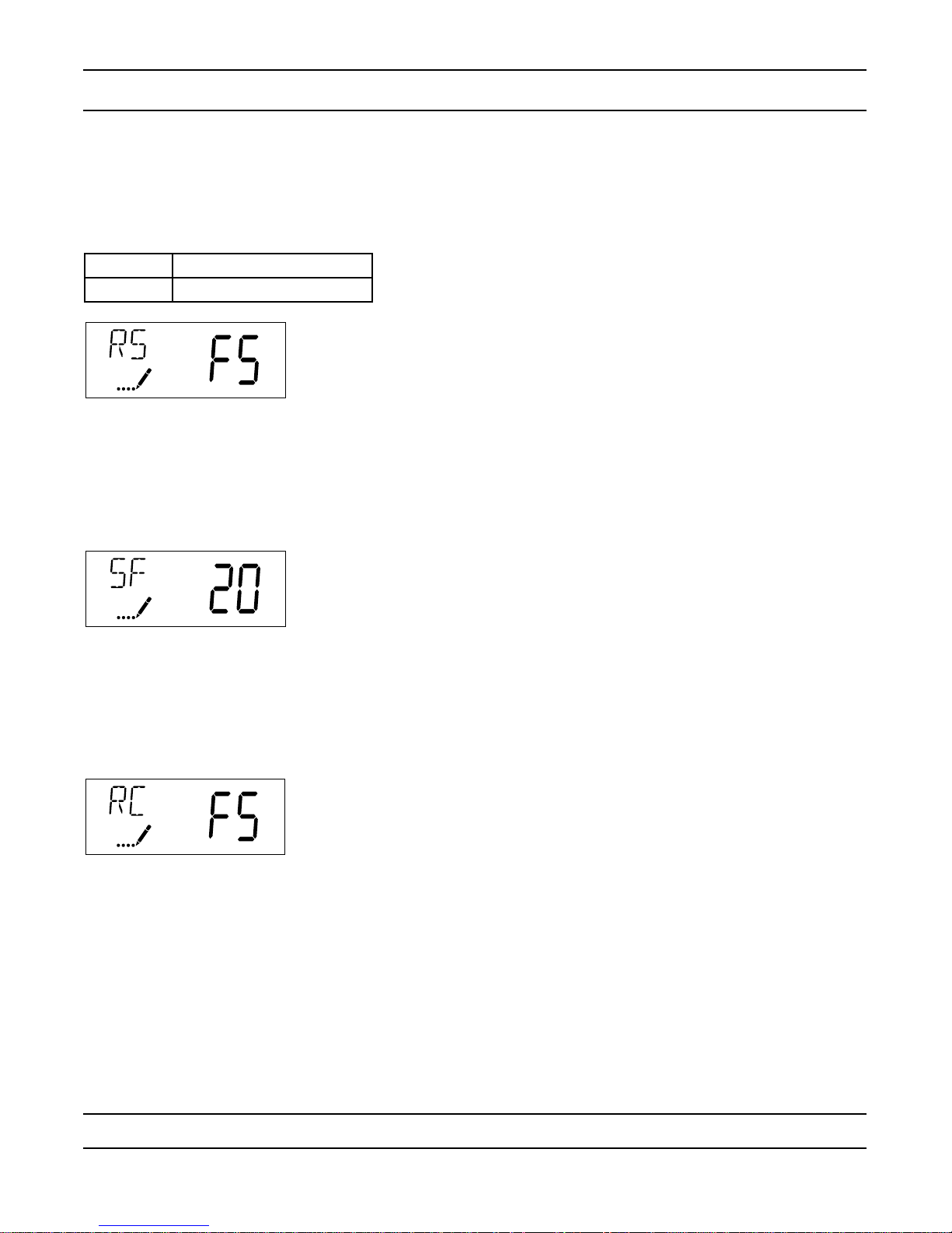
8. Reserve Selection (Display Code RS)
Press the Extra Cycle button. Use this display to set the Safety Factor. Use this display to select the type of
reserve to be used in your system. This setting is identied by “RS” in the upper left-hand corner of the screen.
The reserve selection parameter is only available if the control type has been set to one of the metered options.
There are two possible settings.
FS Safety Factor
rc Fixed Reserve Capacity
.
.
.
.
.
9. Safety Factor (Display Code SF)
Press the Extra Cycle button. Use this display to set the Safety Factor. This setting species what percentage of
the system capacity will be held as a reserve. Since this value is expressed as a percentage, any change to the
unit capacity or feedwater hardness that changes the calculated system capacity will result in a corresponding
change to the reserve volume.This option setting is identied by “SF” in the upper left hand corner of the screen.
Use the Up and Down buttons to adjust the value from 0 to 50% as needed..
.
.
.
.
10. Fixed Reserve Capacity (Display Code RC)
Press the Extra Cycle button. Use this display to set the Reserve Capacity. This setting species a xed
volume that will be held as a reserve. The reserve capacity cannot be set to a value greater than one-half of the
calculated system capacity. The reserve capacity is a xed volume and does not change if the unit capacity or
feedwater hardness are changed. This option setting is identied by “RC” in the upper left-hand corner of the
screen. Use the Up and Down buttons to adjust the value as needed.
CAUTION: Before entering Master Programming, please contact your local professional water dealer.
Page 15
 Loading...