


MODEL 5600SE
Downflow Brining
Service Manual
IMPORTANT: Fill in pertinent information on page 2 for future reference.

MODEL 5600SE Downflow
Job Specification Sheet
Job Number ___________________________________
Model Number ________________________________
Water Test ____________________________________
Capacity Of Unit ________________________ Max. _____________ Per Regeneration
Mineral Tank Size: Diameter ___________________ Height _____________________
Under Bedding ____________________________ Amount _______________________
Type Of Media ____________________________ Cubic Feet _____________________
Brine Tank Size ________________________________
Salt Setting Per Regeneration ________________________________
Valve Programming
Treated Water Capacity ______________________________ (Gallons / Liters)
Regeneration Day Override _______________________________ (Max. Days Between Regen.)
Regeneration Time ________________________________ ( A.M. ) ( P.M. )
Notes:
________________________________________________________________________________
________________________________________________________________________________
________________________________________________________________________________
________________________________________________________________________________
________________________________________________________________________________
________________________________________________________________________________
________________________________________________________________________________
Page 2
Printed in U.S.A.

MODEL 5600SE Downflow
General Residential Installation Check List
WATER PRESSURE: A minimum of 25 pounds of water pressure is required for regeneration valve to operate
effectively.
ELECTRICAL FACILITIES: An uninterrupted alternating current (A/C) supply is required. Please make sure your voltage supply is compatible with your unit before installation.
EXISTING PLUMBING: Condition of existing plumbing should be free from lime and iron buildup. Piping that is built up
heavily with lime and/or iron should be replaced. If piping is clogged with iron, a separate iron filter unit should be
installed ahead of the water softener.
LOCATION OF SOFTENER AND DRAIN: The softener should be located close to a clean working drain and connected according to local plumbing codes.
BY-PASS VALVES: Always provide for the installation of a by-pass valve if unit is not equipped with one.
CAUTION: Waterpressure is not to exceed 120 p.s.i., water temperature is not to exceed 110˚F, and the unit cannot be
subjected to freezing conditions.
Valve Installation and Start-up Procedures
1. Place the softener tank where you want to install the unit, making sure the tank is level and on a firm base.
2. During cold weather it is recommended that the installer warm the valve up to room temperature before operating.
3. All plumbing should be done in accordance with local plumbing codes. The pipe size for the drain should be a
minimum of 1/2″. Backwash flow rates in excess of 7 gpm or length in excess of 20′ require 3/4″ drain line.
4. The 1″ distributor tube (1.050 O.D.) should be cut flush with top of each tank. Note: Only use silicone lubricant.
5. Lubricate the distributor O-ring seal and tank O-ring seal. Place the main control valve on tank.
6. Solder joints near the drain must be done prior to connecting the Drain Line Flow Control fitting (DLFC). Leave at
least 6″ between the DLFC and solder joints when soldering pipes that are connected on the DLFC. Failure to do
this could cause interior damage to DLFC.
7. Teflon tape is the only sealant to be used on the drain fitting.
8. Make sure that the floor is clean beneath the salt storage tank and that it is level.
9. Place approximately 1″ of water above the grid plate. If a grid is not utilized, fill to the top of the air check in the salt
tank. Do not add salt to the brine tank at this time.
10. On units with a by-pass, place in by-pass position. Turn on the main water supply. Open a cold soft water tap
nearby and let run a few minutes or until the system is free from foreign material (usually solder) that may have
resulted from the installation. Once clean, close the water tap.
11. Place the by-pass in service position and let water flow into the mineral tank. When water flow stops, slowly open a
cold water tap nearby and let run until the air is purged from the unit. Then close tap.
12. Plug the valve into an approved power source. Once the valve is powered it will drive to the Service Position.
Page 3
Printed in U.S.A.

MODEL 5600SE Downflow
Control Start-up Procedures
Whenever the valve is in Service the current time of day can be set, the control programmed, or an extra regeneration
initiated at any time.
1.
2.
Set Time Of Day
Push either the Up or Down Set Button once to adjust Time Of Day Display by one digit.
Push and hold either Up or Down Set Button to adjust Time Of Day Display by several digits.
Enter Control Programming Mode
1. Push and hold for 5 seconds both the Up and down Set Buttons to enter Programming Mode.
2. Push the Extra Cycle Button once per display until all have been viewed and this mode is exited and normal
operation is resumed.
Page 4
Printed in U.S.A.

MODEL 5600SE Downflow
Control Start-up Procedures (Cont’d.)
Depending on current control programming, option setting displays that are not required to be set will not be viewed.
3.
1. The first option setting display that appears in the Program Mode is Treated Water Capacity. Using the Set Up
Set Control Programming
or Down Buttons, set the amount of treated water that can flow through the unit before a regeneration is
required. For Example:
2. Push the Extra Cycle Button. The second option setting display that appears is Regeneration time. Using the
Set Up or Down Buttons, set the desired time of day when a regeneration can occur, if required. For Example:
3. Control porgramming is now complete. Push the Extra Cycle Button. This will exit the control from the
Programming Mode, and resume Normal Operation.
4. Control progrmming is now complete. Push the Extra Cycle Button. This will exit the control from the
Programming Mode, and resume Normal Operation.
Page 5
Printed in U.S.A.

MODEL 5600SE Downflow
Control Start-up Procedures (Cont’d.)
4.
When starting an Extra Cycle, you will have one or two options:
1. Press and Release the Extra Cycle Button:
2. Press and Hold for 5 seconds the Extra Cycle Button:
Start An Immediate Extra Cycle
With Immediate Regeneration controls the control will go into regeneration cycle immediately.
- With Delayed Regeneration controls the Service Arrow will begin to flash immediately and a regeneration
will occur at the present regeneration time (i.e. 2:00 a.m.)
- With Delayed Regeneration controls this will force the control to go into regeneration cycle immediately.
5.
Page 6
Regeneration Cycle Displays
The following series of displays appear when the control enters a regeneration cycle:
Printed in U.S.A.

MODEL 5600SE Downflow
Control Start-up Procudures (Cont’d.)
6.
Next, manually step the valve through a regeneration cycle checking valve operation in each step:
Fast Cycle Valve Thru Regeneration
A. Once the valve reaches Regen Step #1 let water run to drain for about 5 minutes.
B. Push the Extra Cycle Button once to advance the valve to Regen Step #2.
C. Push the Extra Cycle Button once to advance the valve to Regen Step #3. (Optional)
D. Push the Extra Cycle Button once to advance the valve to Regen Step #4. (Optional)
E. Push the Extra Cycle Button once more to advance the valve back to Service.
7.
Final Set-Up
With proper valve operation verified:
A. Add water to the top of the air check. Manually step the valve to the Brine Draw Position and allow the
valve to draw water from the brine tank until it stops. Note: The air check will check at approximately the
midpoint of the screened intake area.
B. Next, manually step the valve to the Brine Refill Position and allow the valve to return to Service
automatically.
C. With the valve in Service, check that there is about 1.0″ of water above the grid in the brine tank, if used.
D. Fill the brine tank with salt.
E. Set-Up is now finished, the control can now be left to run automatically.
Page 7
Printed in U.S.A.
MODEL 5600SE Downflow
Control Operation
Timeclock Regeneration Valves
In normal operation the Time Of Day Display will be viewed at all times. The control will operate normally until the
number of days since the last regeneration reaches the Regeneration Day Override setting. Once this occurs, a
regeneration cycle will then be initiated at the preset Regeneration Time.
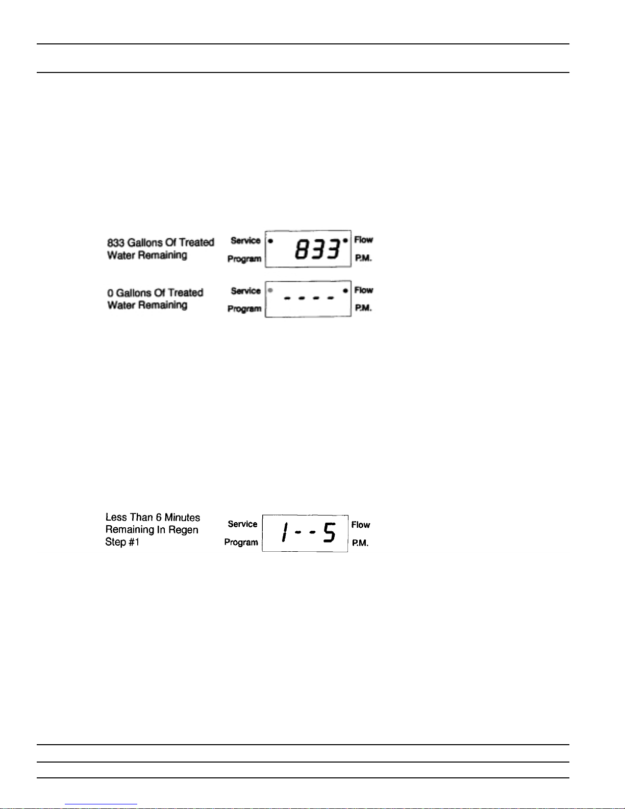
Flow Meter Equipped Valves
In normal operation the Time Of Day Display will alternate being viewed with a Volume Remaining Display. This display
will be in gallons. As treated water is used, the Volume Remaining Display will count down from a maximum value to
zero or (----). Once this occurs a regeneration cycle will then be initiated immediately or delayed to the set
Regeneration Time. Water flow through the valve is indicated by the Flow Dot that will flash in a direct relationship to
flow rate. For Example:
Immediate Regeneration Valves With Days Between Regeneration Override Set
When the valve reaches its set Days Since Regeneration Override value a regeneration cycle will be initiated
immediately. This event occurs regardless of the Volume Remaining display having reached zero gallons.
Delayed Regeneration Valves With Days Between Regeneration Override Set
When the valve reaches its set Days Since Regeneration Override value a regeneration cycle will be initiated at the
preset Regeneration Time. This event occurs regardless of the Volume Remaining display having reached zero
gallons.
Control Operation During Regeneration
In Regeneration the control will display a special Regeneration Display. In this display the control will show the current
regeneration step number the valve is advancing to, or has reached, and the time remaining in that step. The step
number displayed will flash until the valve has completed driving to this regeneration step position. Once all
regeneration steps have been completed the valve will return to Service and resume normal operation. For Example:
Pushing the Extra Cycle Button during a regeneration cycle will immediately advance the valve to the next cycle step
position and resume normal step timing.
Control Operation During Programming
The control will only enter the Program Mode with the valve in Service. While in the Program Mode the control will
continue to operate normally monitoring water usage and keeping all displays up to date. Control programming is
stored in memory permanently, without the need for battery backup power.
Control Operation During A Power Failure
During a power failure all control displays and programming will be stored for use upon power re-application. The
control will retain these values for years, if necessary,without loss. The control will be fully inoperative and any calls for
regeneration will be delayed. The control will upon power re-application resume normal operation from the point were
it was interrupted. An indication that a power outage has occurred will be an inaccurate time of day display.
Page 8
Printed in U.S.A.

MODEL 5600SE Downflow
Water Conditioner Flow Diagrams (Downflow Brining)
Using Black Cycle Cam (Part No. 17438)
Service
Position
Backwash
Position
(Regeneration Cycle Step #1)
Page 9
Printed in U.S.A.
 Loading...