

Page 1

Table of Contents
Section 1 - System Definitions……………………………………………………….. 3
Board Layout and Connections……………………………………………..3
System Definitions………………………………………………………….4
Section 2 - System Overview………………………………………………………….4
Radio Thermostat………………………………………………………….4
Base Unit…………………………………………………………………..4
DC-Motorized Valve Actuator…………………………………………….5
Section 3 - User Interface……………………………………………………………..5
Section 4 - Getting Started……………………………………………………………5
Section 5 - System Setup and Configuration/Initialization…………………………6
Radio Thermostat Initialization……………………………………………..6
Master Cooling Setup…………………….…………………………………7
Section 6 - Uninstalling a Radio Thermostat…………………………………………7
Master Reset…………………………………………………………………7
Section 7 - Mounting the Base Unit and Wiring…………………………………….8
Section 8 - Signal Strength…………………………………………………………….9
Section 9 - Output Test Mode…………………………………………………………9
DC-MVA Output Test………………………………………………………10
Dry Contact………………………………………………………………….10
Section 10 - Radio Thermostat………………………………………………………..10
Mounting…………………………………………………………………..10
Operation…………………………………………………………………..11
Section 11 - System Ready…………………………………………………………….11
Section 12 - Troubleshooting………………………………………………………….12
Section 13 - Technical Specifications…………………………………………………13
Page 2

This device complies with Part 15 of the FCC rules: Operation is subject to the following conditions: (1) this device may
not cause interference, and (2) this device must accept any interference, including interference that may cause undesired
operation of this device
Antenna Connection - The Wirsbo Genius™ control system is designed to use a radio
signal opposed to typical low voltage wiring. The external antenna provided must be
connected for proper system operation.
Cooling Contact - When the Wirsbo Genius is operating in “cooling” mode, this
connection can be used enable an air handle, furnace, etc., for air conditioning
requirements. This contact is locked out in the heating and off modes. This is an
unpowered or dry contact.
Heating Contact - When the Wirsbo Genius is operating in “heating” mode, this
connection can be used to enable a boiler, pump relay or other types of heating devices.
This is an unpowered or dry contact.
Mode Indicator LED - The LED changes color to indicate the mode of operation. The
indicator will change from Orange (off) to Red (Heating) to Green (Cooling). These
LEDs are visible through a display window on the front cover on the Genius™
Mode Selector Switch - Used to change mode of operation (Off-Heat-Cool) on the
Genius™ When the front cover is installed, this switch can be operated by pressing the
right hand corner of the display window.
Modular Connector - This port is used during the installation of the Radio Thermostats.
Using the cable provided with this package, one end is plugged into this port and the other
into the back of the Radio Thermostats. See Section XX for Radio Thermostat
Initialization.
Modular Zone Output - These 10 connections are for operation and connection of the
DC-style Motorized Valve Actuator (MVA). The female connector on the Genius board
is keyed to ensure the plug on the DC-MVA is wired properly.
Important: The Wirsbo Genius is designed for use with the DC-MVA only. Use of other
unapproved actuators will provide unsatisfactory operation.
Power Supply - The Wirsbo Genius Base Unit comes pre-wired with a 6’ power cord and
plug. Simply plug in to standard 115 volt receptacles.
Pump Connection - Power supply to a circulator (if used) in a radiant or other hydronic
application. This output is only active in the heating mode.
Status Indicator LEDs - Visible through the display window when the cover is installed,
these LEDs will change color and flash to provide systems feedback (communication,
Page 3

error, valve failure, antenna signal strength, etc.). Through out this manual, these LEDs
will be discussed in further detail based on the mode of operation.
Temperature Units Switch - This switch position will determine whether the Radio
Thermostat will display temperature in °F or °C. Units must be selected prior to installing
the Thermostats.
User Interface Buttons - These are used during system initialization and are not required
for normal operation. See pages xx-xx for additional information.
Page 4

Section 2: System Overview:
The Wirsbo Genius system is a radio controlled system for radiant floor heating and other
hydronic applications. Primary system components are Radio Thermostat, the Base Unit
and the DC-style Motorized Valve Actuator (MVA) as shown below.
Fig 1. Fig.2 Fig.3
The Radio Thermostat (see Fig. 1) communicates with the Base Unit using a completely
wireless link, highlighting ultimate flexibility of placement for indoor temperature
feedback. The Radio Thermostat are mounted on a wall of an area designated as a
“zone”. A zone can be a single room, multiple rooms, a garage or any area where space
temperature control is desired or required. The radio signal and frequency used to
transmit information between the two pieces of hardware will not interfere with common
household appliances such as the microwaves, garage door openers, televisions, etc. The
Radio Thermostat transmits identification number, change in space temperature (actual vs.
setpoint) and will also “talk” to the Base Unit on a random interval to ensure
communication is uninterrupted. Upon a recognized change in room temperature sensed
by the Radio Thermostat, the Base Unit will perform secondary operations based on the
mode of operation (heating or cooling).
The Base Unit (see Fig. 2) upon receiving a change in temperature from the Radio
Thermostat will provide the necessary switching for control outputs based on the mode of
operation. The Wirsbo Genius™ will control:
Heating Mode
• Up to 10 DC-MVA, part number A302xxxx
• One 110 VAC circulation pump or other powered output; max rating ½ HP /
400 VA
• One optional dry contact for interfacing boiler operation or other heating
controls; max rating 110 V, ½ HP / 400VA
Cooling Mode
• One optional dry contact for interfacing air conditioning; max rating 110 V,
½ HP / 400VA
The Base Unit is mounted at the manifold location(s) and can receive communication from
up to 10 Radio Thermostat. Through the Base Unit, each Radio Thermostat has the
ability to control 1 or more outputs to the DC-MVAs by “Zone Mapping”. Simply, Zone
Mapping is the relationship between the Radio Thermostat controlling the proper zone
outputs or DC-MVAs, reacting to a fall in room temperature. Zone Mapping is
Page 5

established during the installation of the Wirsbo Genius™ system and will be covered in
greater detail in Section XX.
The DC-MVAs (see Fig. 3) will open and close, dependent on the signal that Base Unit
receives from the Radio Thermostat, allowing water to circulate through the
corresponding loops of the manifold. The DC-MVA is unique in its design as it does not
require power to remain in the open position; power open/power close. The DC-MVA
has an integral end switch that serves multiple functions. It will not allow the pump to
start until a minimum of 1 end switch has closed during a call for heat and also provides
system feedback through the User Interface to indicate a operator or DC-MVA failure.
Section 3: User Interface
Prior to progressing to the installation of the Wirsbo Genius, it is important to understand
the User Interface and how it works. There are two parts: the buttons (User Interface
Butttons and the Mode Selector Switch) and the LEDs (Status Indicator LEDs and the
Mode Indicator LED). The buttons are used to provide a minimal amount of information
in order to make the Wirsbo Genius operational. The LEDs change color to indicate
certain system functions depending on the mode (installation or normal operation) and are
visible through a clear window after the cover is installed. Once the Wirsbo Genius is
programmed and the cover secured, only the Mode Selector Switch will be required to
change the mode of operation from Off to Heat to Cool. See Fig. 4.
Section 4: Getting Started
To begin system start up and programming of the Wirsbo Genius, we highly recommend
that the programming be completed prior to mounting the Base Unit at the manifold
location. The installation of the Radio Thermostats to the Base Unit can be completed
much easier on a flat surface, such as a desk or table top.
1.) Remove the Base Unit and the required number of Radio Thermostats from their
packaging.
2.) Verify that all the necessary components are included in the packaging. As follows:
Base Unit Radio Thermostat
• Base Unit Control ≤ • Thermostat Wall Unit ≤
• Bag fastening hardware ≤ • 3.6v Lithium Battery (installed) ≤
• Bag containing black wire
w/modular connectors ≤ Other Tools Req’d (not incl.)
• Antenna with cord ≤ • Phillips Screwdriver ≤
• Sheet of labels ≤ • Pen
≤
• Instruction Manual Τ • Wire Cutters/Strippers ≤
Page 6

3.) Using a phillips screw driver, loosen the three (3) screws on the front cover of the
Base Unit and remove the cover. You are now ready to begin installation of the
Genius™ Thermostats
Section 5: System Setup and Configuration/Initialization
Using a wireless frequency to transmit information from a room location to the Base Unit
does not create a physical path (such as wiring) to follow from Point A to Point B. We
will create this relation between the Radio Thermostat and the Base Unit through
initialization. When we initialize a Radio Thermostat, a couple of things happen. The
Radio Thermostat is woken up, a “hand-shake” is created between the two components
and a special identification number/code is recognized by the Base Unit. The Base Unit
will respond, as needed, when a transmission is received with that ID number. Note: The
Radio Thermostat is shipped with the battery installed in a “sleeping” state and must be
awaken to make operational. The “sleep” mode allows the Radio Thermostat to ship the
battery installed while not reducing battery life.
With the background established on how the link is created on the Input side of the
control (Radio Thermostat to Base Unit), we need to understand how to create the Output
function. Simply, what is the Base Unit supposed to do when a change in room
temperature is detected by the Radio Thermostat based on the mode of operation. This is
accomplished through “Zone Mapping”. Zone Mapping is the process of telling the Base
Unit which outputs for the DC-MVAs (in heating mode only) are to operate when a fall in
temperature is detected and is performed at the time of the Radio Thermostat initialization
or wake up.
With the Base Unit laying on a flat surface with the front cover off and the User Interface
Buttons exposed (as shown on page 2), use the following steps to initialize the Radio
Thermostat to the Base Unit:
1.) Plug power cord of the Genius Base Unit into a standard 115V power outlet. Once
this is done, power to the board is confirmed by an “orange” light at the Mode
Indicator LED.
2.) Set Temperature Unit Selector to the proper position (°F or °C).
3.) Using one of the Radio Thermostats to be installed, remove the back cover, exposing
the battery and a modular phone connector jack.
4.) Plug one end of the black cord (provided with the Base Unit) in to the back of the
thermostat and the other into the Modular Connector on the Base Unit. If this is done
properly, the Display on the Radio Thermostat is illuminated (fig. X) and 11 green
LEDs are lit with the one in the number 1 position flashing. If the Temperature Units
were set incorrectly in Step 2, simply unplug the Radio Thermostat at the Base Unit,
correctly set the Units switch and reconnect the cord.
Page 7

5.) The flashing LED indicates the current channel or output awaiting designation. The
arrow buttons are used to change position of channel of the flashing LED and the OK
button is to reserve and tie that output to the ID signature of the Radio Thermostat.
Each number LED corresponds to DC-MVA output connector of that same number.
Using the arrows buttons, move the flashing green LED to the desired channel.
6.) Once the proper channel is selected, press the OK button to confirm your selection. A
solid orange LED is indicated at that position. Unplug the transmitter cable. If the
current Radio Thermostat is to control 1 or more DC-MVAs, return to step 5 as many
times as necessary until all of the actuators are installed. Each time the modular
connector is disconnected and reconnected to the MC, dark LEDs indicate that these
channels are used. The flexibility of Zone Mapping does not require the corresponding
outputs to be side by side.
7.) When all of the actuator outputs have been entered for the current Radio Thermostat,
use the label sheet provide to write in the room name and channel outputs. Remove
this label and place on the back of the thermostat. To install a new Radio Thermostat,
return to step 3.
Installing a Single Radio Thermostat for Cooling
When a Radio Thermostat is connected to the Base Unit, you’ll notice 11 green LEDs are
lit, but only 10 zones of heating can be used. The green LED indicated by the Mode
Indicator LED is used to designate the cooling zone. Simply use the arrow and OK
buttons to select. Now, the current thermostat will control x-number DC-MVAs (as
setup) and provide a master thermostat for cooling. Once this channel is used, it will no
longer illuminate when a Radio Thermostat is connect to the board. It is also suggested
that a designation be placed on the label to indicate this thermostat the master cooling stat.
Section 6: Uninstalling a Radio Thermostat
In the event a thermostat is setup incorrectly and an output needs to be uninstalled, use the
following procedure:
1.) Press and hold the OK button for 5 seconds. All outputs or channels that can be
released are indicated by a solid red LED.
2.) Use the arrow button until the desired channel to be uninstalled is flashing Red.
3.) Press and hold the OK button for another 5 seconds. When the channel is uninstalled,
all previously lit LEDs will turn dark.
Master Reset
Should you find it necessary to uninstall all of the Radio Thermostats and outputs, the
following procedure will erase all data entered into the non-volatile memory during
Page 8

initialization. By pressing and holding ∧, ∨ and OK simultaneously, the master reset
procedure is initiated. The Status Indicator LEDs are used to indicate a countdown
sequence. The LEDs will turn green one by one, then orange and finally red. When all the
LEDs are Red, the non-volatile memory is erased and the Base Unit is in a virgin state for
initialization. The Master Reset can be interrupted at any time by releasing the buttons.
Section 7: Mounting the Base Unit and Wiring
Before installing the Wirsbo Base Unit and connecting for operation, use the following
steps:
1.) Place each of the Radio Thermostats in approximate positions in their dedicated
rooms.
2.) Unscrew the three screws on the front of the Base Unit and remove the cover.
3.) On the enclosure fringe below the output connectors 1…10, dry contacts and the
antenna connections where the material is thin, cut out to provide wire access to the
DC-MVAs, equipment and the antenna. A wire cutter will work best.
4.) Connect power supply cord to 115 volt outlet at the manifold location.
5.) Using the MODE and OK buttons, press simultaneously to enter the Radio Signal
Strength Mode and locate the antenna where reception is optimum and the DC-MVAs
can still reach the Base Unit properly.
Note: The signal strength may be significantly influenced by the position. The Radio
Signal Strength LEDs should be ORANGE or GREEN for all of the thermostats
installed. A dark (unlit) or RED LED indicates the reception is poor and a new
location must be found. See Section 8 for more information of signal strength.
6.) Mark the position of the antenna and the Base Unit
7.) Disconnect the power and antenna from the Base Unit.
8.) Mount the Base Unit in the marked position in a fixed horizontal position on the wall
using the screws and anchors supplied with the unit. Note: The anchors may not be
required when mounting the Genius unit to a solid wall or plywood. Mount the
antenna in its marked position.
9.) If connecting a circulator to the Genius unit, remove plastic cap, allowing access to the
pump terminal connections. Otherwise, skip to Step 11.
10.) Install a conduit connection or suitable connector as required by local codes. Insert
Page 9

wires through connection hub and wire accordingly. Note: Proper grounding of the
conduit hub must be ensured.
11.) If wiring in heating and cooling devices, such as a boiler or water heater, remove the
terminal block and wire outside of the case. By doing so, the wiring connections can
be easily made and the terminal blocks re-installed by pressing onto the posts
attached to the control board. Run wires between tabs at the bottom of the plastic
enclosure
12.) Connect the modular plugs of the DC-MVA to the designated outputs as set up in
Section 5: System Setup and Initialization.
13.) Plug in external antenna and run wire between tabs at the bottom of the plastic
enclosure. Read Section 8 before permanently fixing the antenna into position.
14.) Replace front cover to Genius unit
15.) Apply power to Genius unit by plugging attached power cord into standard
convenience outlet. System is ready for operation indicated by the Orange LED on
the Mode Status Indicator and can be put into Heating (Red LED) or Cooling
(Green
LED) modes of operation.
Section 8: Signal Strength
After installation and wiring of the Genius unit, it may be necessary to verify the signal
strength based on the current position of the antenna and signal received from the Radio
Thermostat. Signal strength can be checked by placing the Base Unit in Radio Quality
Check Mode. By initiating this mode, LEDs #1 - #10 will indicate the strength of the last
signal received from each of the thermostats by the color of the LED. This mode is
activated by pressing the MODE and OK buttons simultaneously. Use the following table
to determine signal strength:
LED
Signal Strength
Color
None Poor
Red Fair
Orange Good
Green Excellent
To leave the Radio Quality Check Mode, press MODE and OK simultaneously
Page 10
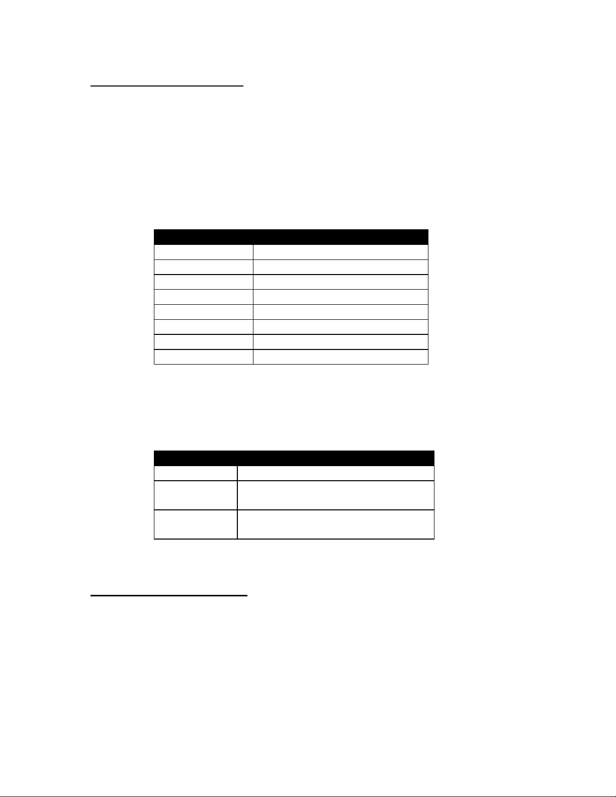
Section 9: Output Test Mode
After the Wirsbo Genius™ is initialized, mounted and wired, a software routine can be
enabled to cycle all system outputs to verify equipment operation and valid wiring. To
enter the Output Test Mode, press the Left and Right arrow buttons simultaneously. In
this mode, the heating and cooling contacts can be activated and the DC-MVAs can be
cycled open/close to verify valve and end switch operations. Use the follow tables to
activate the desired equipment:
DC-MVA Output Test
LED Color Operation
Flashing Orange DC-MVA to be tested
Solid Orange All possible outputs
Solid Green Valve is opening
Off Valve is closing
Buttons Function
Left Arrow Select previous output
Right Arrow Select next output
OK Start/Stop test on selected output
Note: If the open/close cycle is interrupted during either of the cycles, the valve
will return to the full closed position.
Dry Contact Test
LED Color Signal Strength
Solid Orange Both heat and cool demands are open
Solid Red Heat demand is closed
Cooling demand is open
Solid Green Cooling demand is closed
Heat demand is open
Pressing the Left and Right Arrow button simultaneously will end the Output Test Mode.
Section 10: Radio Thermostat
The installation and set is nearly complete. Mounting the Radio thermostat and
understanding the operation is all that remains.
**** Mounting ****
Using the information recorded on the label placed on the back of the Radio Thermostat
back in Section xx, find the room(s) that this will monitor the room temperature for. Find
Page 11

a flat surface suitable for mounting. Do not mount the thermostat or select a location
where the thermostat may be affected adversely by temperature (fireplaces, windows,
lamps, etc.). However, the design of a wireless system allows the thermostat location to
be moved easily. Use the following steps for mounting the Radio Thermostats:
1.) Using a pencil, mark the wall for the upper mounting location.
2.) Use a level to draw a line down towards the floor. Line should be approximately 2.5”
in length.
3.) Mark the lower screw position 2-3/8” from the upper mark on the level line.
4.) Install the screws and anchor combinations depending on the wall construction if
required. Leave approximately 1/16” of threads exposed.
5.) Place holes in back cover of thermostat over screw heads and snug to the wall.
6.) Gently press down on the top of the thermostat to snap into position.
**** Operation ****
In order to make the Genius system functional, it is important to understand the operation.
The thermostat continually monitors room temperature and any changes along with
intermittent “checks” with the Base Unit. The LCD display on the thermostat will display:
• Temperature Unit (°F/°C) • Current Room Temperature
• Set Room Temperature • Low Battery Indicator
In heating mode, a decrease in room temperature will active the dedicated DC-MVAs, the
dry heating and pump contacts. In cooling mode, a rise in room temperature will active
the dry cooling contact. The Base Unit will carry out the proper function and maintain
room temperature comfort based on the inputted setting. To set the room temperature,
use the following steps:
1.) Press the gray dome to indicate the current room temperature setting. When the
adjustment mode is activated, “SET” will be indicated in LCD display.
2.) Turn the gray dome to change desired room temperature. The display will
automatically return to showing room temperature after 10 seconds. Note: Turning
the dome will change the room set temperature without having “SET” displayed.
Section 11: System Ready
With all of the above steps completed, the Wirsbo Genius is now ready for operation.
Returning to the location of the Base Unit, pressing the Mode Selector Switch will move
the mode of operation from standby to heating (or cooling if pressed twice). This is
visible and indicated by the Mode Indicator LED changing colors. Use the table below as
a guide to interpreting system function and mode of operation:
LED Color Status Indicator LEDs Mode Indicator LED
Page 12

Dark Idle No Power
Solid Orange ------ Standby Mode
Solid Red ------ Heating Mode
Solid Green Heat Demand Cooling Mode
Flashing Green Communications from thermostat -----Flashing Red Missing communications ------
Section 11: Troubleshooting
Symptom Cause Remedy
• Genius will not switch to
cooling mode
• Radio thermostat was not set
up on channel 11
• See Section xx for Cooling
Thermostat setup
• Base Unit not responding to
changes in room temperature
• Radio thermostat operates
wrong DC-MVA(s)
• Flashing RED on Status
Indicator LED
• Solid RED on Status
Indicator LED
• “BAT” is indicated on LCD
display of Radio Thermostat
• No display on Radio
Thermostat LCD window
• Verify that thermostat is
initialized to base unit
• Lost Communications
• External Antenna missing
• DC-MVA Output(s)
designated to wrong radio
thermostat
• Lost communication with
Radio Thermostat
• Missing Thermostat
• Low battery life
• DC-MVA end switch not
functioning properly
• Motor Failure
• Lithium battery life is low • Replace battery
• Battery removed from unit
• Radio thermostat has not
been initialized
• See Section xx for checking
signal strength
• Change antenna position
• Connect Antenna
• See Section xx for
initialization and setup
• Check signal strength
• Remount thermostat
• Replace battery
• Check valve function -
Section xx
• Replace actuator
• Replace battery
• See Section xx for Radio
Thermostat initialization
• When Base Unit is plugged
in, no ORANGE LED
• Base Unit receives call for • Pump connections wired • Check wiring connections
• No power to at outlet
• Short in power cord
• Contact qualified electrician
• Replace Base Unit
Page 13

heat but pump will not
operate
wrong
• Fuse is blown
• Replace fuse
• Radio Thermostat display
reads incorrect temperature
units (°F/°C)
• Front cover on Base Unit
will not close properly
• Temperature Units Switch
was set incorrectly on
initialization
• Cut outs for wiring
connections not removed
• See Section xx to correct
• Remove plastic tabs to
provide access for wiring.
See Section xx - step x
Section 12: Technical Specifications
General
Ambient temperature: 32-122°F / 0-50°C
Ambient humidity < 90%
Weight aa Base Unit
bb Radio Thermostat
cc DC-MVA
Control Unit
Rated voltage: 110V, 60Hz
Incoming frequency: 433.92 MHz
Quiescent current consumption: .15 Amps
Maximum current consumption: 4.1 Amps
Power consumption at max.
system configuration: 470 VA
Protection class P 30
Dimensions L x W x D 2.25” x 4.25” x 2.40”
Pump Output: 110 VAC, 1/3 HP max.
Boiler Relay Output dry contact, 400VA max
Air Conditioning Relay dry contact, 400 VA
Output
User Settings after power failure: Remain stored
Max number of radio thermostats 10
to be installed
DC-MVA power consumption .025 Amps
per unit
Max. number of DC-MVA to be 10
connected
Max. number of DC-MVAs to be 1
connected per modular output
Approvals: cUL, File # Exxxxx
FCC, ID #yyyyy
IC, # zzzzzzz
Page 14

Radio Thermostat
Energy supply: 3.6 V lithium battery, service life
appr. 2,000 mAh
Transmitter frequency 433.92 MHz
Range: 75 feet
Dimensions: 2.33” x 4.71” x 1.19”
Display: Fahrenheit / Celsius
Display Range: 0 - 99°
Setpoint Range: 40 - 90°F / 4 - 32°C
Differential: 1°F / 0.5°C Heating
2°F / 1.1°C Cooling
 Loading...