

Page 1
#PKPCUTS PSI Woodworking Products
3 IN 1 PIZZA CUTTER/SLICER/SERVER
Kit Features Required Accessories
• Slices and Serves
• Stainless Steel Construction
• Easy to Turn
• Flat to round component eliminates
need for ferrule
• Minimal Parts--easy to assemble
Preparing the Blank:
• Cut blank to the desired size, length range should be between 4 to 6
inches.
• Drill 1/2” hole in one end of blank to a depth of at least 1 inch.
• Drill 15/32” hole lengthwise through the rest of the blank.
• If you do not wish to use a through hole and instead want to just drill
two end holes See alternative turning method (Dia. F) on reverse.
Headstock
End Bushing
Server Side
• 7mm Pen Mandrel
• Drill Bits: 15/32” #PK-1532 and 1/2” #PKDB12
• Bushing Set(pc): #PKGCALL2BU
• Live Tailstock or Mandrel Saver
• 2 part Epoxy
• Pen Blank Minimum Size: 1-1/2” x 1-1/2” x 4”L
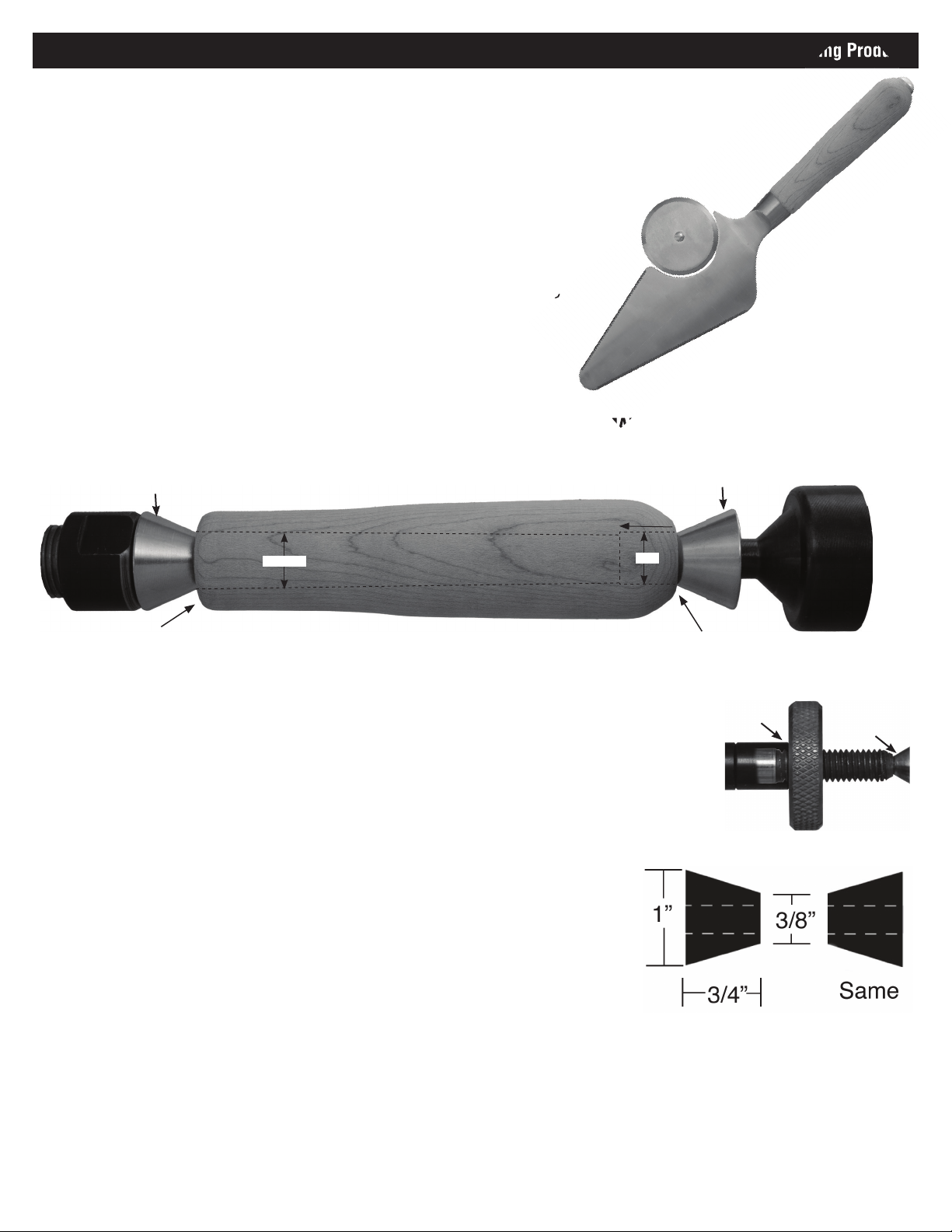
DIAGRAM B / TURNING THE BLANK ON THE MANDREL
End Cap Side
Mandrel Saver
Tailstock
End Bushing
15/32”
Turn to approx.15/16”
Turn Blank to a profi le of your choice
Turning the Blank on a mandrel: (Refer to Dia. F to turn between centers)
• Mount the bushings and blanks according to Diagram B. PKGCALL2BU will
automatically center in the holes.
• When using Mandrel Saver, there is no need for extra spacer bushings or the
knurled nut. Slide and lock tailstock directly against bushings and tighten quill
until blank and bushings are secure.
• To use Knurled Nut Setup (right), add spacer bushings until past the threads on
the end of the Mandrel Shaft.
• Thread on the Knurled Nut and hand tighten to hold all components in place.
• Slide the Tailstock up snugly against the Mandrel shaft, inserting the live center
point into the Mandrel dimple.
• Lock Tailstock and hand tighten the quill adjustment with wheel to steady the
mandrel. Do not over-tighten, it could damage mandrel shaft.
Instructions for either method: (Turning on a Mandrel or between centers)
• Using sharp tools, turn the blank down. Note that the 12.5mm hole will be on
the Server side and the 1/2 in. hole is needed for the End Cap. Turn your profile
with the correct orientation for this arraignment. Turn the barrel straight or to a
profile of your choice.
• Turn the Server end down to approximately 15/16” and the End Cap end to
approximately 5/8”. Round the edge to blend with the parts.
• Sand the blank down to be flush with the bushings, gradually increasing
sandpaper grits.
• Finish the barrel using your choice of polish. Since handle will need to be
washed regularly, we recommend using an oil based finish such as Mahoney’s
Utility Oil (#LBUFFOIL). Allow sufficient time for the polish to cure—refer to polish
manufacturer’s instructions.
1” deep
1/2”
Turn to approx. 5/8”
Knurled Nut Setup
Add spacer bushings past
the threads
Live Center
Diagram C / Bushing #PKGCALL2BU
Page 2
#PKPCUTS
PSI Woodworking Products
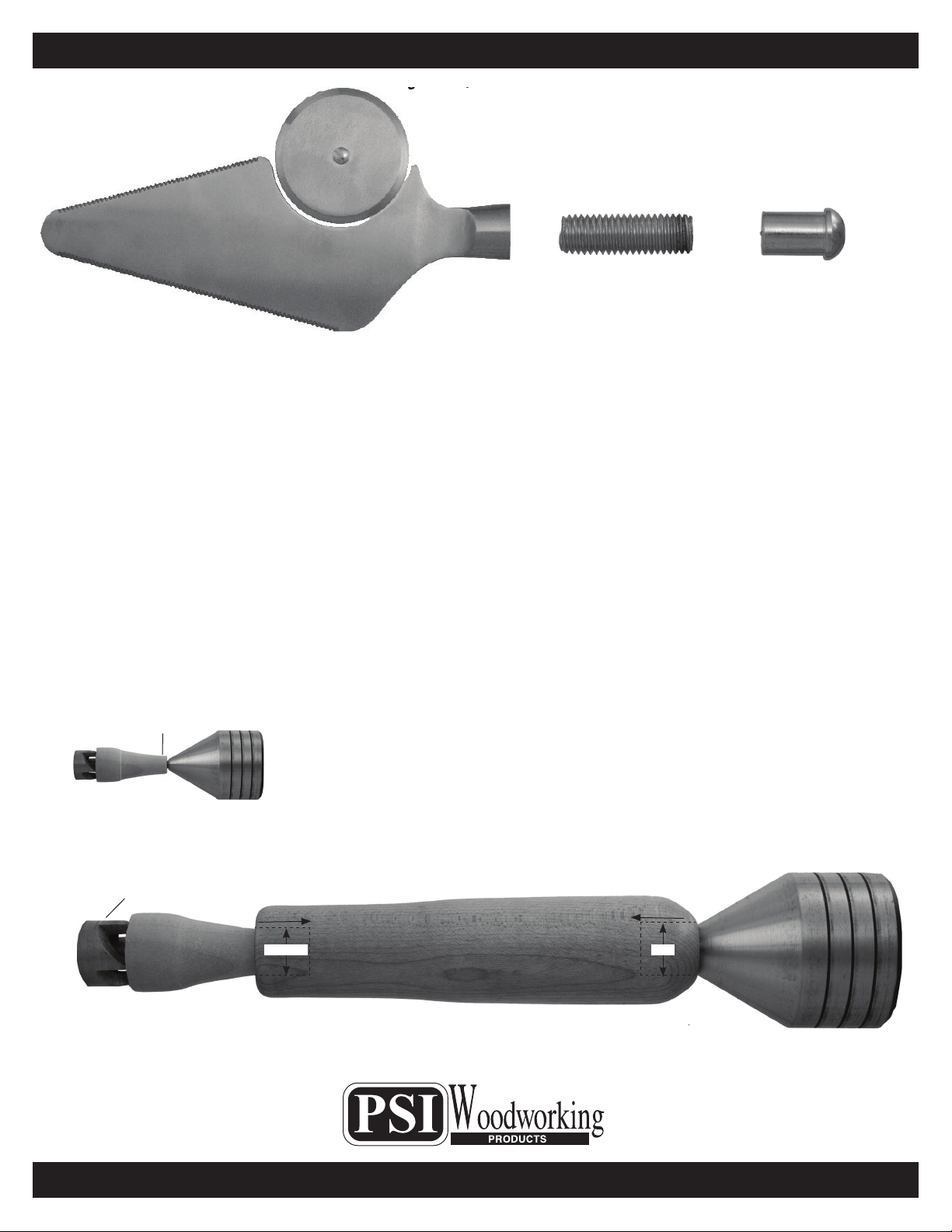
Diagram D / Parts Layout
Slicer
End CapThreaded Post
Assembly:
• Thread Post into the opening in the bottom of the Server.
• Mix and apply epoxy inside the end holes of the blank.
• Apply a light amount of epoxy onto the threaded Post and slide into the side of the blank with the smaller hole.
• Apply a small amount of epoxy onto End Cap post and slide it into remaining, larger hole.
• Set aside for epoxy to cure. You can help clamp the parts in the handle by using plastic wrap, winding several layers
from top to bottom.
• Once Epoxy has fully cured, the Server/Slicer is ready to use.
• Washing by hand is recommended. Avoid putting wooden handle into dishwasher. Refresh finish as need with oil
such as that used for maintaining butcher blocks.
Alternative turning method:
• Find center of each endan drill holes in each. One end should be drilled with a 12.5mm bit and the other should be
drilled wih 1/2 inch bit. Both holes must be at least 1 inch deep.
• Turn a Jam Chuck between centers. It should taper down so the narrow end is around 12mm in diameter (Dia. F).
• Mount Handle between jam chuck and 60° center as shown in Diagram F.
• Complete as described under “Instructions for either method” on the reverse page.
Diagram E / Making the Jam Chuck
12mm Diameter
Diagram F / Turning between centers with a Jam Chuck
4 Prong Drive Center
Turned Jam Chuck
Server Side
1-1/4” deep
15/32”
End Cap Side
1” deep
1/2”
60°
Tailstock Center
© 2022 PSI Woodworking Philadelphia PA 19115 - v10/22
 Loading...