

Penn Scale PC-400 Installation Manual
Model PC-400
Portion Control Scale
Operator’s Manual
Doran Scales, Inc.
1315 Paramount Pkwy
Batavia, IL 60510
1-800-262-6844
www.doranscales.com
Man. #233 Manual Revision 0.1
i

Table of Contents
Section 1. Unpacking and Installation ..................................................... 1
Unpacking: ................................................................................................................................................................1
Installation: ................................................................................................................................................................1
Electrical Connections:..............................................................................................................................................1
Care & Cleaning:.......................................................................................................................................................1
Section 2. Scale Operations Guide ......................................................... 2
Display Functions:.....................................................................................................................................................2
Basic Weighing: ........................................................................................................................................................2
Units Select:...............................................................................................................................................................2
Battery: ......................................................................................................................................................................2
Power:........................................................................................................................................................................2
Section 3. Setup and Calibration Guide.................................................. 3
Power connections:....................................................................................................................................................3
RS-232 Connections:.................................................................................................................................................3
Calibration and Parameter Setup: ..............................................................................................................................3
Analog Setup: ............................................................................................................................................................4
Section 4. Battery...................................................................................... 5
Charging: ...................................................................................................................................................................5
Replacement: .............................................................................................................................................................5
Voltage Levels:..........................................................................................................................................................5
Battery Voltages.........................................................................................................................................................5
Section 5. Parameter Setup ..................................................................... 6
Entering and Exiting Setup Mode: ............................................................................................................................6
Changing a Parameter:...............................................................................................................................................6
Changing Start up Units: ...........................................................................................................................................6
Legal for Trade Restrictions: .....................................................................................................................................6
Section 6. Setup Menus Explained.......................................................... 7
Resoluton (divisions) Setup Menu.............................................................................................................................7
Capacity Setup Menu.................................................................................................................................................7
Calibration Menu(s)...................................................................................................................................................7
Auto Off Mode ..........................................................................................................................................................8
Auto Zero Tracking ...................................................................................................................................................8
Motion Aperture ........................................................................................................................................................8
Start Up Zero .............................................................................................................................................................8
Data Output ...............................................................................................................................................................9
Data Format ...............................................................................................................................................................9
Baud Rate ..................................................................................................................................................................9
Convert Select ...........................................................................................................................................................9
Startup Units............................................................................................................................................................10
Operation Mode.......................................................................................................................................................10
Raw Counts .............................................................................................................................................................10
Section 7. Data Communications .......................................................... 11
Introduction to data communications: .....................................................................................................................11
Printer Modes: .........................................................................................................................................................12
Data Output Format:................................................................................................................................................13
Bi-directional Communications:..............................................................................................................................16
RS232 Pin-outs:.......................................................................................................................................................16
Section 8. Specifications......................................................................... 17
Section 9. Troubleshooting.................................................................... 18
ii

Section 1. Unpacking and Installation
Unpacking:
Before unpacking your Doran scale, please read the instructions in this
section. Your new scale is a durable industrial product, but it is also a
sensitive weighing instrument. Normal care should be taken when
handling and using this product. Improper handling or abuse can
damage the scale and result in costly repairs that may not be covered by
the warranty. If you notice any shipping damage, notify the shipper
immediately. Please observe the following precautions to insure years
of trouble free service from your new scale.
! DO NOT drop the scale.
! DO NOT immerse the scale.
! DO NOT drop objects on the scale.
Carefully remove the scale from the shipping carton. Be sure to retain
all shipping materials in case the scale must be shipped elsewhere.
Installation:
Place the scale on a stable flat surface. Verify that the bubble level
located under the platter shows that the scale is level. Adjust the four
feet to obtain a level condition (bubble in center.)
Electrical Connections:
The PC-400 uses a wall mounted transformer or an internal
rechargeable battery to provide power to the scale. The transformer
requires 115 VAC, 50/60 Hz power. Be sure that the power outlet and
transformer are not exposed to water while the scale is plugged in.
Care & Cleaning:
With reasonable care, this product will last for many years. Here are
some tips to care for your PC-400 Portion Control Scale.
•
Hand clean with a damp cloth using mild detergent.
Do not wash the scale in a dishwasher – the removable platter is
•
dishwasher safe.
Do not use strong solvents or abrasive cleaners as this can damage
•
the touch panel or other plastic parts.
Do not drop or overload the scale.
•
Do not use sharp objects to press any of the buttons.
•
Always use the PC-400 on a stable, vibration-free surface for best
•
weighing results.
Do not immerse.
•
1
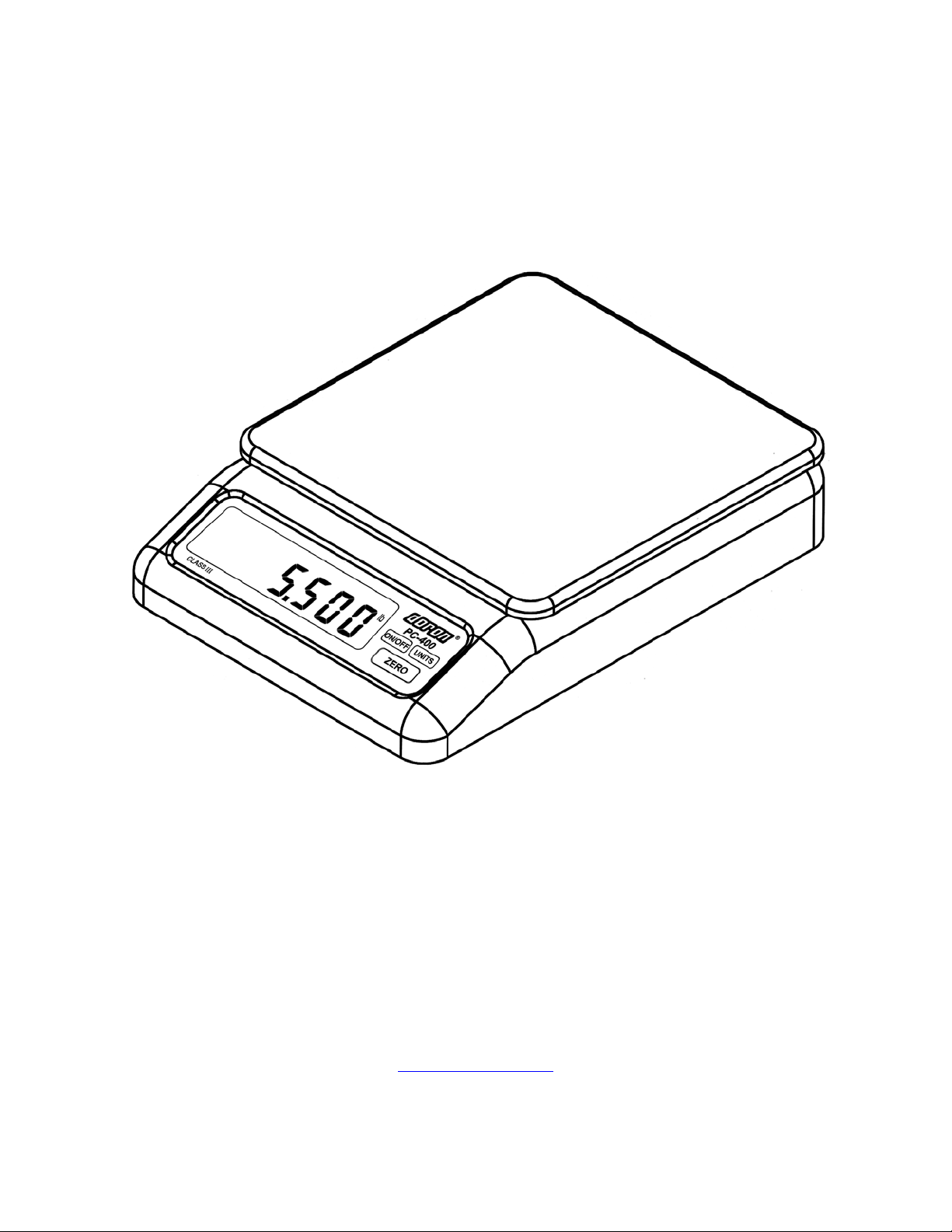
Section 2. Scale Operations Guide
Fig. 1 PC-400
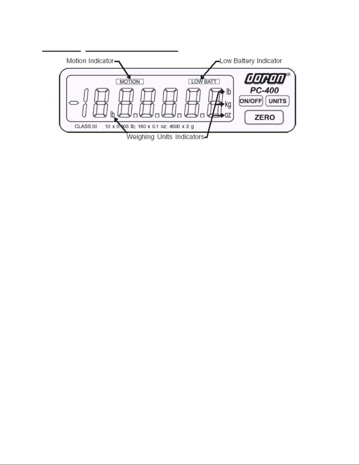
Display Functions:
The Model PC-400 controls consist of ON/OFF, UNITS and ZERO buttons located
next to the main LCD display. The display is used to provide weight indications
and operator messages describing scale operation.
Basic Weighing:
1. Select the desired weighing units by pressing the UNITS button.
2. Empty the scale platter and press ZERO to zero the scale.
3. Place an item on the scale platter and wait for the MOTION indicator to go out.
4. Read the weight on the display.
Units Select:
Press the UNITS button to change weight display units from lb to oz to kg to g to
lb:oz.
Battery:
When the battery needs to be recharged, the “LO BAT” indicator illuminates.
Power:
The PC-400 is powered by an AC wall transformer or the internal rechargeable
battery, both standard features. Turn the scale on or off by pressing ON/OFF.
Automatic Sleep Function:
The PC-400 has a feature called “Auto Shut-down” that turns the scale off after a
preset time of no activity. This helps conserve battery life. The preset time is
selectable from 1 minute to 60 minutes or it can be disabled so the scale remains
on continuously. The default setting is 5 minutes.
2
Section 3. Setup and Calibration Guide
Power connections:
The PC-400 is powered from a wall mounted transformer or the internal
rechargeable battery. The transformer has a power cord which plugs into the
power jack located on the back of the scale.
RS-232 Connections:
The PC-400 has a standard RS-232 output. To use this feature, the optional RS232 cable is needed. Plug one end of the RS-232 connector into the RJ-12
connector located on the rear of the scale. Attach the other end to your
computer or printer.
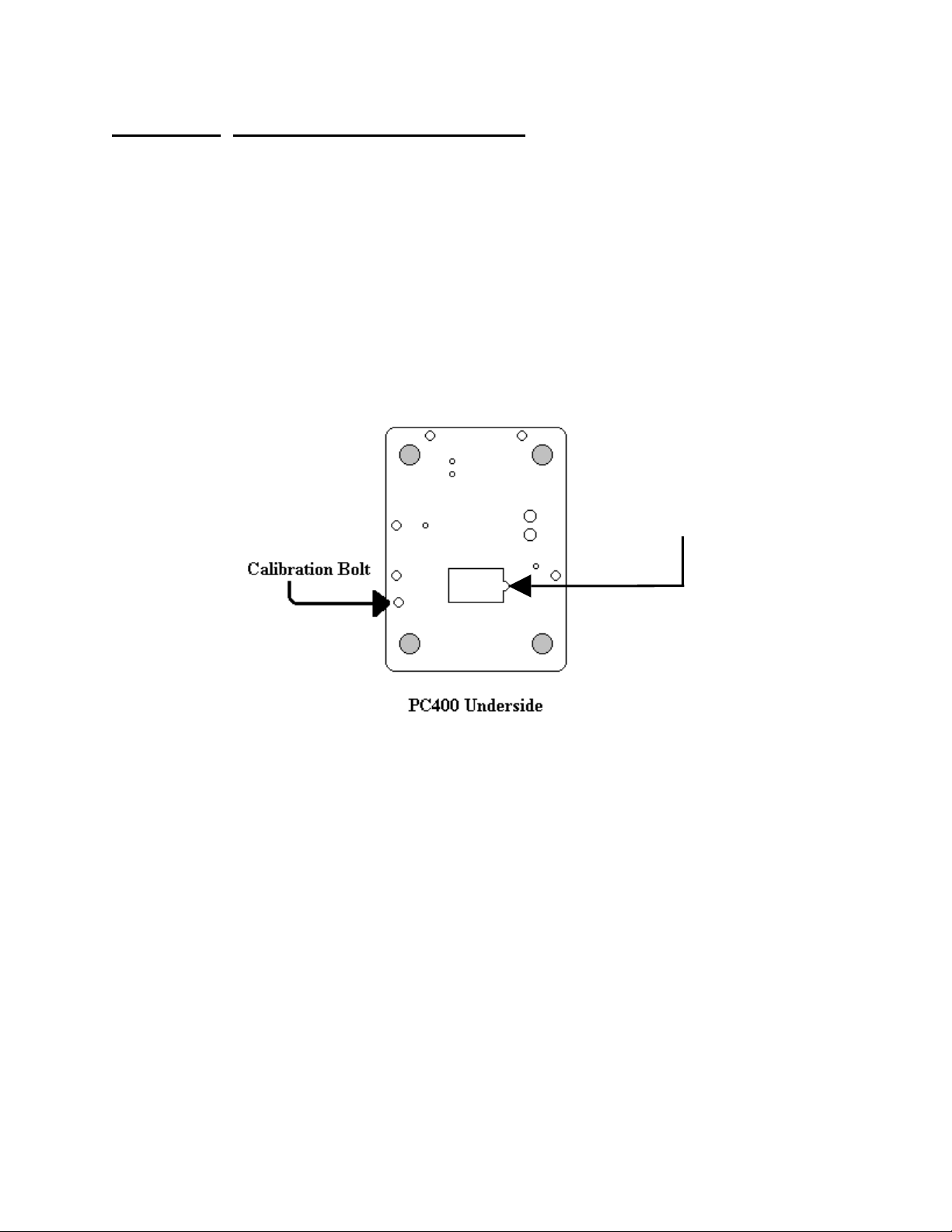
Calibration and Parameter Setup:
Battery
Compartment
Cover
1) After applying power to the PC-400, remove the platter, turn the scale over
and remove the calibration bolt as shown above. Place a thin blunt object
through the hole and press straight down. The scale should enter the
Setup/Calibration mode, and the scale should display “div 2.5” (or “div 5.0“or
“div 10” depending on the scale resolution.)
2) Turn the scale upright, replace the platter and press the UNITS button twice.
The scale should now display “CAL 0”.
3) Remove any unnecessary weight from the scale platter. Press ZERO. Wait
for the scale to count down from “7” to “0”. If the scale detects motion, the
display will restart the count. When finished, the display will return “CAL F5”.
NOTE: If “r9 Err” appears on the display, the calibration zero is out of range.
Press ZERO to clear this error. Refer to the analog setup section for
additional information.
3
4) Place full capacity (2lbs for the 2.2lb scale and 12lbs for the 13.2lb scale) on
the platter and press ZERO. Wait for the scale to count down from “7” to “0. If
the scale detects motion, the count will restart. When finished, the scale will
return to the weigh mode.
NOTE: If “SPnL” or “SPnH” appears on the display, the calibration span is out of
5) If additional parameter changes are needed, refer to Chapter 4.
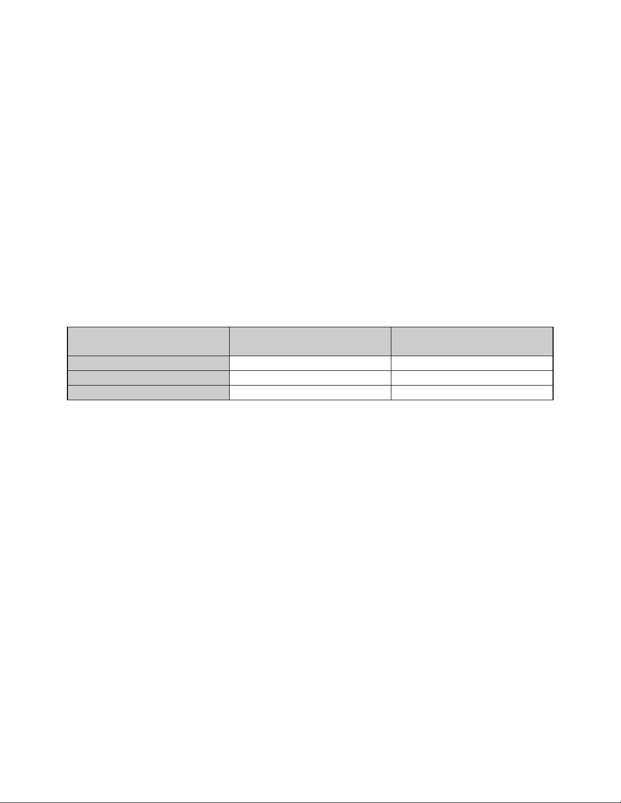
Analog Setup:
The following table shows the acceptable “Raw Counts” for no load and full load.
“Raw Counts” can be viewed through the last setup parameter. Refer to Section
4, Parameter Setup, for more information regarding parameter viewing.
If the scale’s raw counts are not within the ranges specified in the following table,
load cell may need to be replaced.
range. Verify that the calibration weight is correct and repeat the
calibration. Refer to the analog setup section for additional information.
Scale Capacity Acceptable “Raw Counts”
for no load
Acceptable CHANGE in
“Raw Counts” for full load
2 lb 18,500 – 41,000 64,500 – 92,500
5 lb 14,500 – 35,250 110,000 – 143,000
10 lb 6000 – 24,000 120,500 – 153,000
4

Section 4. Battery
Charging:
The Model PC-400 can be operated by the Internal Rechargeable Battery. The
typical battery life is 15 hours of continuous use. The scale will display LOW BATT
in the LCD display panel when the battery needs to be recharged.
To recharge the battery, follow these steps:
1. Insert the power connector into the rear of the scale.
2. Plug the power cord into an AC outlet (115 VAC). If the scale is turned off, four
moving dots will appear on the bottom of the display. As the battery charges,
the dots, beginning on the left, will remain on. When the scale is fully charged,
all four dots will remain on. It takes approximately four hours to completely
recharge the battery. The PC-400 can be used while it is being recharged.
3. The scale is ready to use, powered by the fully recharged battery.
Replacement:
The Model PC-400 is powered by an internal rechargeable battery. If the battery
loses its ability to maintain a charge, it will need to be replaced. Replace the battery
following these steps:
Remove any items from the scale platter and unplug the power cord from the
1.
rear of the scale.
Remove the scale platter and set it aside.
2.
Turn the scale over and remove the phillips head screw on the battery
3.
compartment cover.
Remove the cover and disconnect the old battery from the battery connector and
4.
replace it with a new battery.
Please note that the battery connector is keyed and insertion should not require
5.
a lot of force. If the connector will not go in place, check to make sure the
connector has the correct orientation.
Replace the battery compartment cover and the phillips head screw.
6.
Voltage Levels:
To view the voltage of the battery, perform the following steps:
• Turn on the scale and wait for a stable weight to be displayed.
• Press and hold UNITS.
• Press and release ON/OFF.
• Release UNITS.
The battery voltage is now displayed.
Battery Voltages
Battery/Scale condition Voltage Level
Fully Charged 8.4V
Low Battery 6.3V
Shut Off 6.0V
5
 Loading...