

Penn Scale FS-15Ki Installation Manual

Check Weighing Scales
FS-6Ki
FS-15Ki
FS-30Ki
1WMPD4001332

This Manual and Marks
All safety messages are identified by the following, “WARNING” or “CAUTION”, of ANSI Z535.4
(American National Standard Institute: Product Safety Signs and Labels). The meanings are as
follows:
WARNING
CAUTION
This is a hazard alert mark.
Note This manual is subject to change without notice at any time to improve the product. No part of
this manual may be photocopied, reproduced, or translated into another language without the
prior written consent of the A&D Company.
Product specifications are subject to change without any obligation on the part of the
manufacture.
A potentially hazardous situation which, if not avoided, could result
in death or serious injury.
A potentially hazardous situation which, if not avoided, may result in
minor or moderate injury.
Copyright 2006

Contents
1. COMPLIANCE ................................................................................................. 2
2. INTRODUCTION.............................................................................................. 3
3. UNPACKING.................................................................................................... 3
4. CAUTION.........................................................................................................4
4-1. Precautions for Installing the Scale........................................................... 4
4-2. Precautions for Operating the Scale ......................................................... 4
4-3. Precautions for Storing the Scale.............................................................. 4
5. SETTING UP.................................................................................................... 5
5-1. Attaching a display pod to the display support column.............................. 5
5-2. Installing the scale..................................................................................... 5
6. NAMES AND FUNCTIONS.............................................................................. 6
7. BASIC OPERATION ...................................................................................... 10
7-1. Turning the power ON and OFF.............................................................. 10
7-2. Selecting a weighing unit......................................................................... 10
7-3. Basic operation ....................................................................................... 10
7-4. Weighing with Preset Tare........................................................................11
7-5. To Clear a Tare Weight.............................................................................11
7-6. Weight display resolution ........................................................................ 12
7-7. Simplified operation mode.......................................................................12
7-8. LCD backlight.......................................................................................... 12
8. CHECK WEIGHING ......................................................................................... 13
8-1. Target weight setting mode ..................................................................... 13
8-2. Upper & Lower limits weight setting mode .............................................. 16
8-3. The comparator memory......................................................................... 17
9. ANALOG SWEEP DISPLAY ............................................................................ 19
9-1. Selecting a display mode ........................................................................ 19
9-2. Example of the analog sweep display..................................................... 20
10. CALIBRATION............................................................................................. 22
10-1. Calibration using a weight..................................................................... 22
10-2. Gravity acceleration correction..............................................................23
11. FUNCTIONS................................................................................................. 24
11-1. The procedure for setting parameters................................................... 24
11-2. Function list........................................................................................... 25
12. SPECIFICATIONS........................................................................................ 27
12-1. Specifications........................................................................................ 27
12-2. Dimensions ........................................................................................... 28
13. GRAVITY ACCELERATION MAP................................................................ 29
1

1. COMPLIANCE
Compliance with FCC rules
Please note that this equipment generates, uses and can radiate radio frequency
energy. This equipment has been tested and has been found to comply with the
limits of a Class A computing device pursuant to Subpart J of Part 15 of FCC rules.
These rules are designed to provide reasonable protection against interference
when equipment is operated in a commercial environment. If this unit is operated in
a residential area it might cause some interference and under these circumstances
the user would be required to take, at his own expense, whatever measures are
necessary to eliminate the interference.
(FCC = Federal Communications Commission in the U.S.A.)
Classification of protection provided by enclosures
The equipment is designed to comply with the IP Code of IEC 60529.
The “IP65” is explained as follows:
“IP” International Protection.
“6” Against ingress of solid foreign objects.
Dust-tight. No ingress of dust.
“5” Against ingress of water with harmful effects.
Protected against water jets (no power full jets). Water projected in jets
against the enclosure form any direction shall have no harmful effects.
NSF listed
The equipment is certified and listed to NSF/ANSI Standard 169 by NSF
International. NSF International evaluated the equipment and certified that it is
compliant with food protection and sanitation requirements for the design,
construction and materials.
2
2. INTRODUCTION
r
This manual describes how this scale works and how to get the most out of it
in terms of performance.
FS-i series check weighing scales have the following features:
The FS-i series has three kinds of weight display resolution, 1/3,000, 1/6,000
(~1/7,500) and 1/12,000 (~1/15,000) to cover various applications.
There are 2 sizes of weighing pan. The FS-30Ki has a larger pan and the FS-6Ki /
FS-15Ki has a smaller pan.
Weighing units are kg kilogram, g gram, lb pound; oz ounce; and lb-oz pound and
ounce.
Waterproof to IP-65 specifications.
Constructed from stainless steel for harsh working environment.
Large liquid crystal display with back lighting and analog sweep display of 60
segments with back lighting.
Scale may be operated by AC power source or an optional SLA (sealed lead acid)
battery.
Built in comparator with large and bright LED display of results.
Three colors of comparator results for better visibility.
Two modes of comparator operation, Target weight setting and Upper/Lower limits
setting.
Optional serial data and comparator relay interface.
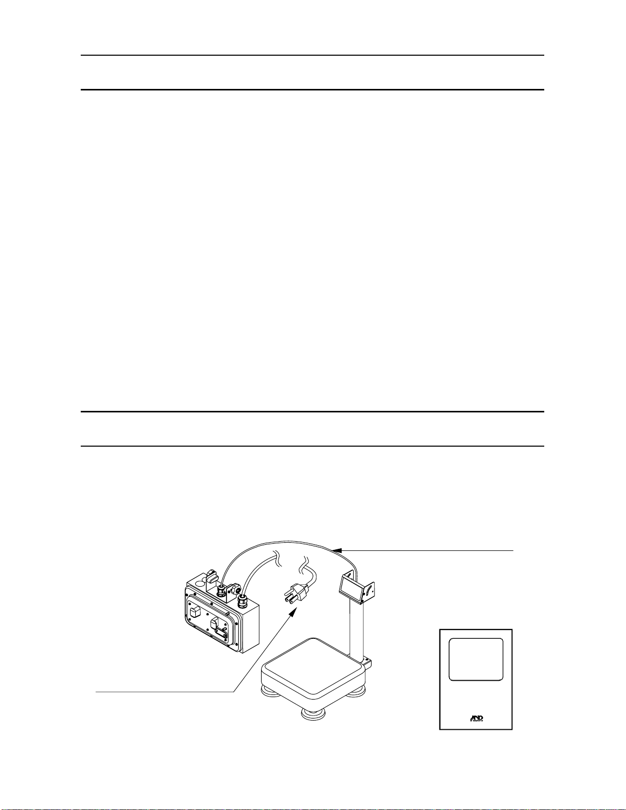
3. UNPACKING
Unpack the scale carefully and keep the packing material if you are likely to transport
the scale again in the future.
When unpacking, check whether all of the following items are included:
CAUTION
Do not pull the load cell cable.
Instruction manual
Display pod
Main power cord
Please confirm that the main
power type is correct for you
local voltage and receptacle.
Weighing pan
Base unit
FS-i series
INSTRUCTION MANUAL
3

4. CAUTION
4-1. Precautions for Installing the Scale
Ground the scale so that the user will not be subjected an electric shock.
Do not handle the main power cord with wet hands.
The AC plug is not water-resistant. Install it in an area where it does not get wet.
Do not install the scale where there is flammable or corrosive gas present.
Do not install the scale under water.
Do not pull, fold or arrange cables forcibly.
Consider following conditions to get the most from your scale.
Install the scale where the temperature and relative humidity is stable. There is no
draft and a stable power source is available.
Install the scale on a solid and level surface.
Do not install the scale in direct sunlight.
Do not install the scale near heaters or air conditioners.
Do not install the scale where there is flammable or corrosive gas present.
Do not install the scale near equipment which produces magnetic fields.
Do not install the scale in a place where it is apt to be chraged with static electricity,
or where the relativ e humidity is lower than 45% RH. Plastic and isolators a re apt to
be charged with static electricity.
Do not use an unstable power source.
4-2. Precautions for Operating the Scale
Periodically ensure that the weighing value is correct.
Calibrate the scale periodically to keep weighing accuracy (See “10. CALIBRATION”).
Calibrate the scale when you move it to another location.
Do not place anything on the pan that is heavier than the weighing capacity.
Do not apply a shock load to the scale.
Do not use a sharp instrument such as a pencil or ball-point pen to press the keys.
Make sure that the STABLE annunciator is ON whenever reading or storing a value.
We recommend you to press the ZERO or TARE key before each weighing
to prevent possible error.
4-3. Precautions for Storing the Scale
Do not disassemble the scale.
Do not use solvents to clean the scale.
For best cleaning of the display pod, wipe with a lint free cloth that is dry or
moistened with warm water and mild detergent.
The base unit is can be cleaned with gentle water jet and brushing. Dry the unit well
before use.
Do not use a powerful water jet.
4

5. SETTING UP
yp
5-1. Attaching a display pod to the display support column
1. Take out whole of the scale from the box
taking care not to pull the load cell cable.
2. Remove 2 clamps and 2 M4x12 screws.
Displa
3. Attach the display pod to the display
support column and tighten the
M4x12 screws removed at step 2.
4. Attach the clamps and tighten them
after tilting the display pod where
you like to use.
Put the excess part of the load cell
cable into the display support
column
Clamp
M4x12 screws
Clamp
od
5-2. Installing the scale
1. Select the place for installing the scale.
Refer to “Cautions for installing the scale”
below.
2. Adjust the level of the base, using the spirit
level and leveling feet. There is an extra
foot under the display support column.
Adjust this foot to reach floor after adjusting
the level of the base.
3. Connect the main power cord to the outlet that
has the earth wiring. You may use the earth
terminal on the rear side of the display pod
to ground the scale.
4. If necessary, adjust the viewing angle of the
display by loosening the 2 clamps, changing
the angle and re-tightening the clamps.
Earth
terminal
Spirit
level
Earth
terminal
Clamps
Leveling foot
Column
support foot
5

6. NAMES AND FUNCTIONS
Display pod
CAL switch cover
Cable hook
Display
column
Weighing pan
`
6
Earth
terminal
Column
support foot
Spirit level
Leveling foot
5
1
2
8
7
9
10
4 4
3
11
6
12

1
WEIGHT DATA DISPLAY.
This display shows the weight on the weighing pan.
2
WEIGHING UNIT INDICATOR.
This display area shows the weighing unit in use.
3
ANALOG WEIGHT DISPLAY.
This scale has a 60 segments analog sweep display representing zero to full
scale when the simple weighing mode display is selected. In the limit check
weighing display mode, this display shows comparison limits and results.
4
OVER RANGE INDICATORS.
This mark comes ON when the weight is outside the range of analog sweep
display..
5
COMPARISON INDICATORS.
The indicators LO (RED), OK (GREEN) and HI (YELLOW) show the results of
the weight comparison.
6
ST ABLE ANNUNCIA T OR.
This annunciator will come ON when the weight reading is STABLE.
7
ZERO ANNUNCIA TOR.
This annunciator will come ON when the scale is showing the center of ZERO.
8
NET ANNUNCIA TOR.
This annunciator will come ON when the scale is displaying the NET weight on
the weighing pan.
9
PT ANNUNCIA T OR.
This annunciator will come ON when the scale is displaying the preset tare
weight.
10
PRINT ANNUNCIA T OR.
This annunciator will come ON for a moment when the scale sends out the
weight data by pressing the PRINT key or auto-printing.
11
PRECAUTION AGAINST LOW BATTERY.
This annunciator will come ON when the optional battery is getting close to low
battery.
12
KEYPAD.
A 13 key pad provides control and number keys.
7

Description of Key Operations
y
r
play
play
ON/OFF Key
The ON/OFF key turn the power on or off. When turned
on, the scale will be automatically set to zero (power-on zero).
ZERO / ± Key
The ZERO key zeros the scale when the weight is stable
(STABLE annunciator ON). In the data entry sequence this
key switches the sign “+” and “-”.
TARE Key
The TARE key switches the scale to net weight mode and
zeros the weight display when the weight is plus and stable.
The ZERO and NET annunciators will come ON.
PT Key
The PT key is used to enter a tare weight via the 10-ke
pad.
SAMPLE / 9 Key
The SAMPLE key will register the sample weight as the
target. In the data entry sequence this key displays the
KEY / 8 Key
The KEY key allows you to enter a target weight using the
keypad. In the data entry sequence this key displays the
RECALL / 7 Key
The RECALL key is used to recall target weight and/o
HI/LO limits. In the data entry sequence this key displays the
HI / 6 Key
The HI key allows you to enter the comparator HI limit
using the numeric keypad. In the data entry sequence this key
dis
s the number 6.
LO / 5 Key
The LO key allows you to enter the comparator LO limit
using the numeric keypad. In the data entry sequence this key
dis
s the number 5.
8

STORE / 4 Key
r
t
The STORE key is used to store target weight and/o
HI/LO limits. In the data entry sequence this key displays the
DISP. / 3 Key
When the DISP. key is pressed the analog weight display
steps through the 4 available modes of simple weighing, targe
weighing, limit check weighing and display off. In the data
entry sequence this key displays the number 3.
UNITS / 1 Key
The UNITS key is used to select the desired weighing unit .
In the data entry sequence this key displays the number 1.
PRINT / ENT Key
The PRINT key is used when the serial data option OP-03
or OP-04 is installed and sends one data string. In the data
entry sequence this key is used to ENTER the numeric data
into the scale memory.
C Key
The C key is used to clear an incorrect data entry from the
numeric keys.
0 and 2 Keys
These keys are used to display the number 0 or 2 during a
data entry sequence.
9
 Loading...