

Penn Engineering 2000 Original instruction
OPERATION AND
MAINTENANCE
MANUAL FOR THE
PEMSERTER®
SERIES 2000® PRESS
(Original instruction)

OPERATION AND MAINTENANCE MANUAL
PEMSERTER
SERIES 2000
PRESS
MODEL SERIES 2000
FASTENER INSTALLATION PRESS
SERIAL NUMBER 20010- ___
20110- ___
®
PennEngineering
99 Chenfeng Middle Road
Kunshan, Jiangsu Province . PRC
+86(512)5726-9310 www.pemnet . com
PRODUCED IN CHINA BY PEM (CHINA) Co., Ltd
Document Part Number 8021244
Main Document Number 8022050
Revision B July-2016

Copyright 2016 by PennEngineering®, Inc. All rights reserved.
No part of this documentation may be reproduced, copied or transmitted in any form, or by any
electronic, digital or other means, without permission in writing from PennEngineering®, Inc.
(referred to herein as the “Company”). This includes photocopying and information storage and
retrieval systems. The material in this documentation is subject to change without notice.
PLEASE READ THESE TERMS AND CONDITIONS CAREFULLY BEFORE USING THE
SOFTWARE INCLUDED WITH THE EQUIPMENT. BY USING THE SOFTWARE
ACCOMPANYING THE EQUIPMENT YOU AGREE TO BE BOUND BY THE TERMS
AND CONDITIONS OF THIS LICENSE.
All software furnished with the equipment is on a licensed basis. The Company grants to the
user a non-transferable and non-exclusive license to use such software in object code only and
solely in connection with the use of the equipment. Such license may not be assigned,
sublicensed, or otherwise transferred by the user apart from the equipment. No right to copy a
licensed program in whole or in part is granted. Title to the software and documentation shall
remain with the Company. The user shall not modify, merge, or incorporate any form or portion
of a licensed program with other program material, create a derivative work from a licensed
program, or use a licensed program in a network. The user agrees to maintain the Company’s
copyright notice on the licensed programs delivered with the equipment. The user agrees not to
decompile, disassemble, decode, or reverse engineer any licensed program delivered with the
equipment, or any portion thereof.
LIMITED WARRANTY: The Company warrants only that the software will perform in
accordance with the documentation accompanying the equipment during the equipment warranty
period. The Company does not warrant that the software is error free. The user’s exclusive
remedy and the Company’s sole liability for defects in the software as to which the Company is
notified during the equipment warranty period is to repair or replace the software at the
Company’s option. This limited warranty does not apply if the software has been altered, the
user has failed to operate the software in accordance with this documentation, or the software has
been subject to abnormal physical or electrical stress, misuse, negligence or accident.
EXCEPT FOR THE EXPRESS WARRANTY SET FORTH ABOVE, THE SOFTWARE IS
PROVIDED “AS IS” WITH ALL FAULTS. THE COMPANY DISCLAIMS ALL OTHER
WARRANTIES, EXPRESSED OR IMPLIED, INCLUDING, WITHOUT LIMITATION,
THOSE OF MERCHANTABILITY, FITNESS FOR A PARTICULAR PURPOSE AND
NONINFRINGEMENT OR ARISING FROM A COURSE OF DEALING, USAGE, OR
TRADE PRACTICE.
IN NO EVENT SHALL THE COMPANY BE LIABLE FOR ANY INDIRECT, SPECIAL,
CONSEQUENTIAL, OR INCIDENTAL DAMAGES, INCLUDING, WITHOUT
LIMITATION, LOST PROFITS OR LOSS OR DAMAGE TO DATA ARISING OUT OF THE
USE OR INABILITY TO USE THE EQUIPMENT, THE SOFTWARE OR ANY PART OF
THIS DOCUMENTATION, EVEN IF THE COMPANY HAS BEEN ADVISED OF THE
POSSIBILITY OF SUCH DAMAGES.

PEMSERTER
SERIES 2000
FASTENER INSTALLATION PRESS
OPERATION AND MAINTENANCE MANUAL
TABLE OF CONTENTS
SECTION TITLES PAGE
1. INTRODUCTION 1
2. IDENTIFYING AND LOCATING MAJOR COMPONENTS OF THE PRESS 6
3. SAFETY SYSTEM OPERATION 15
4. PRESS INSTALLATION 17
5. GENERAL FUNCTION DESCRIPTIONS 23
6. TOUCH-SCREEN CONTROLS 27
7. PNEUMATIC-HYDRAULIC SYSTEM 70
8. ELECTRICAL SYSTEM 73
9. TOOLING SET-UP 79
10. PRESS OPERATION 94
11. MAINTENANCE 97
12. TROUBLE SHOOTING 109
13. SPARE PARTS 119

Read Manual Before Operating Press!
SECTION 1
INTRODUCTION
The PEMSERTER Series 2000 Fastener Installation Press is available in three configurations:
Manual, Automatic, and as TRU-Motion® systems integrated with material handling systems
such as assembly conveyors, X-Y positioning tables, and robotic arms. This manual describes
the standard Automatic version of the Series 2000 press. The Manual version of the Series
2000 operates the same as the Automatic version with the same control software, except that
the autofeed hardware is not available. A Manual Series 2000 can be upgraded to Automatic by
adding the autofeed system components.
Features:
• Safety and Protection System, sensitive down to 0.4 mm (0.015”)
• Unique high speed ram approach with energy efficient power stroke.
• Computer control system with touch screen interface. Provides simple and precise controls
for the operator. Designed for easy set-up, operation, maintenance and diagnostics.
• Quick Set-up/change-over automatic feed tooling system. Provides an extensive selection of
tooling for different fasteners using the same feeder bowl.
Specifications:
• Ram Force 1.8 to 71.2 KN (400 to 16,000 lbs)
• Pressure System Type Air-Over-Oil
• Air Requirements 6 to 7 BAR (90 to 100 PSI)
12 mm (1/2”) dia. minimum line flow
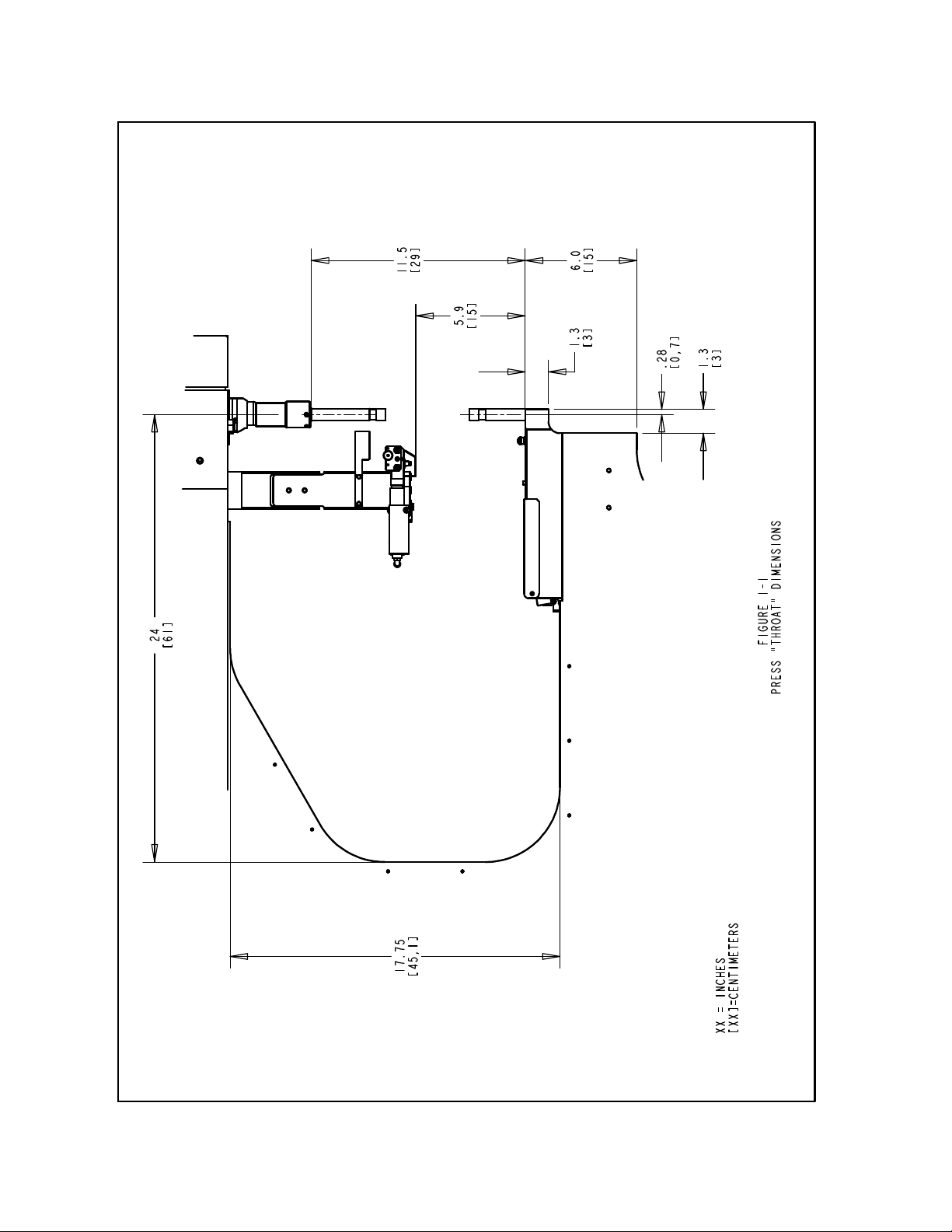
• Throat Depth 61 cm (24”)
• Height 193 cm (76”)
• Width 92 cm (36”)
• Depth 126 cm (49.5”)
• Weight 1,135 kg (2,500 lbs.)
• Electrical (North America) 120VAC(+/-12 VAC), 60 Hz(+/-1 Hz), 5A, 1φ
• Electrical (Europe and Pacific Rim) 230VAC(+/-23 VAC), 50 Hz(+/-1 Hz), 3A, 1φ
• Air Consumption approx. 7 liters/sec air at 1 Atm (15 Scfm)
30 insertions per minute at 20 KN (4500 Lbf)
• Electrical Power Consumption approx. 250 Watts with auto feed bowl running
• Ambient Temperature 41° F to 104° F (5° C to 40° C)
• Transport / Storage Temperature -13°F to +130°F (-25°C to +55°C) and for short
periods not to exceed 24 hours up to 160°F (70°C)
• Ambient Humidity 30% to 95% (Not reflective of inlet air)
• Installation Altitude Max 1000m
Copyright 2016 by PennEngineering®
1 of 119

SAFETY
The Series 2000 was designed to conform to applicable ISO, ANSI, OSHA, CEN and CSA
safety standards.
The Series 2000 is compliant to applicable European Union (EU) directives and bears the
CE Mark.
The Series 2000 conforms to the essential requirements of the following directives:
Machinery Directive 2006/42/EC.
Electromagnetic Compatibility (EMC) Directive 2004/108/EC
Low Voltage Directive 2006/95/EC
Please read and follow the safety precautions listed below.
SAFETY PRECAUTIONS
♦ Always use safety goggles when operating or maintaining the press
♦ Ear Protection is recommended.
♦ Always shut off the electrical power and remove the power cord before servicing the press.
♦ Before using the press, make sure that a shutoff device has been fitted on the air supply line
and the location is easily accessible, so that the air supply to the press can be shut off in an
emergency. Make sure that surge protection is installed in the electrical supply to the press.
♦ Check the air hose and fittings regularly for wear.
♦ Use only approved parts for maintenance and repairs.
♦ Do not use chipped, cracked or damaged accessories and tools.
♦ Attach air line securely.
♦ Keep body parts away from moving parts.
♦ Never wear jewelry, loose clothing or anything that could get caught in moving parts.
♦ If a new user is operating the press, be sure these instructions are readily available.
♦ Do not use the press in any way, other than for its intended purposes.
♦ Do not modify the press in any way.
♦ Fasteners are blown at a high velocity. Tubing must always be secured before machine is
operated. Check integrity of tubing before use.
♦ Press contains hydraulic fluid. See enclosed Material Safety Data Sheet for proper handling.
Follow all applicable local safety standards.
The sound emission values (acoustic pressure level) at the operator position is 93dB(A)
Within the scope of 1 meter ,The sound emission values (sound power level) is 103 dB(A)
Within the scope of 1 meter , uncertainty K=2dB(A) .
However , If the machine is operated in a room with other machines ,the sound emission
level (rated level) can be over 85 dB(A) .
If this is the case , improve the acoustics in the room . If you do not , the hearing of the
operators may be damaged .
WARNING: Immediately upon receipt of your press, establish a “Maintenance
Code” for your supervisor/maintenance personnel only, as it is possible, however
difficult, to operate the press without the standard safeguards in place in the
Copyright 2016 by PennEngineering®
2 of 119
Maintenance Mode. Only trained personnel should use the Maintenance Mode.
PennEngineering
is not responsible for improper maintenance mode procedures,
which result in a loss of operation of the press or operator safety.
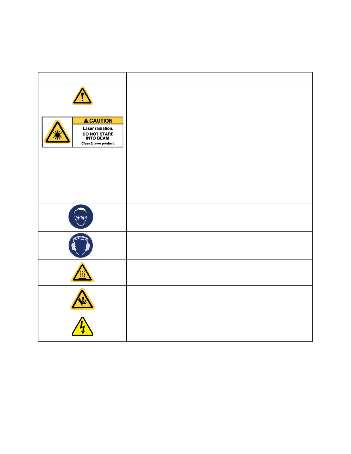
Label Definition
General Warning Label – There are items that require attention.
These are specified in the operator’s manual.
CAUTION: Laser Radiation. Do not stare into beam.
Class 2 laser product.
Per EN 60825 and ANSI Z136.1: Class 2 lasers are low power
devices emitting visible radiation in the wavelength range
400mm to 700mm. Momentary viewing is not considered
hazardous since the upper radiant power limit on this type of
device is less than the MPE (Maximum Permissible Exposure)
for momentary exposure of 0.25 second or less. Intentional
extended viewing, however, is considered hazardous.
Never aim the spotting light anywhere except at the workpiece.
Eye Protection Label – Eye protection must be worn when
operating the press.
Ear Protection Label – Ear protection must be worn when
operating the press.
Hot Surface Label – Hot Surface. Do not touch.
Pinch Point Label – Keep hands away from area.
Electrical Shock/Electrocution Warning Label –Electrical shock
hazard. Do not touch
Copyright 2016 by PennEngineering®
3 of 119

WARRANTY
PennEngineering® warrants that this product, when correctly used according to directions and under normal
operating conditions, will be free from defects in material and workmanship for a period of two (2) years from the
date of purchase.
This warranty shall not apply to any product which has been altered, changed or repaired, normal maintenance
excluded, except as authorized by PennEngineering®. This warranty shall not apply to any product that has been
subject to misuse, negligence or accident.
The purchaser’s exclusive and sole remedy shall be limited to repair, modification or replacement at the discretion
of PennEngineering®. In no event shall PennEngineering® be liable for the cost of any indirect or consequential
damage. In no case shall PennEngineering® liability exceed the purchase price of the product.
This warranty is exclusive and in lieu of all other warranties. No oral or written information by PennEngineering®,
its employees, representatives, distributors or agents shall increase the scope of the above warranty or create any
new warranty.
Should any questions or problems arise concerning your Series 2000 press, contact the PennEngineering® Service
Department. Toll-free telephone number 1-800-523-5321 (in North America) or 215-766-8853.
Set-up, Training and Repair Service is available to you as long as you own your press. Free telephone
instruction and Service is available for the lifetime of your press by calling the PennEngineering® Service
Department.
Copyright 2016 by PennEngineering®
4 of 119
Copyright 2016 by PennEngineering®
5 of 119

SECTION 2
IDENTIFYING AND LOCATING MAJOR COMPONENTS OF THE PRESS
Identifying Major Components of the Press
This section introduces the user to the major components of the press.
Frame
The frame is the structure of the press. The main section is made of solid steel with welded
components that form the base and the other support sections. All parts are directly or indirectly
mounted onto the frame.
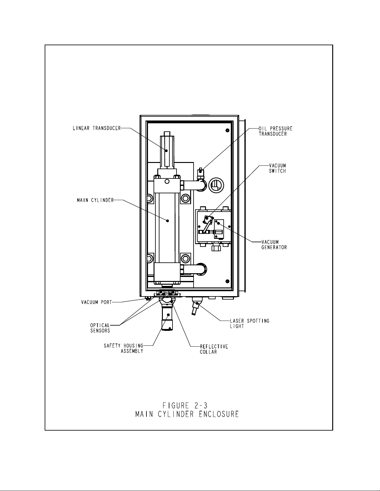
Main Cylinder/Ram
The ram force of the press is exerted by a hydraulic cylinder called the Main Cylinder. It is
mounted directly onto the frame surrounded by the front enclosure. Attached to the main
cylinder, at the back end, is a sensor probe called a Linear Transducer, which reads the location
of the main cylinder piston. Attached to the end of the main cylinder rod is the safety assembly,
described in Section 3. The main cylinder rod is referred to as the Ram.
Operator Controls
All the operator controls are located on the door of the Front Enclosure except the foot pedal.
These include the Touch Screen, the E-Stop button, the Power ON button, the Power OFF
button, the Audible Beeper, and the Spotting Light button.
• Touch Screen - This is the primary interface to the press control system (the PLC). It is
used for installation and automatic feed setup and configuration, feedback to the user and
diagnostics. The screen displays text and graphical information and allows the operator to
make selections by touching different parts of the screen as indicated by what is displayed on
the screen. The touch screen is programmed with an automatic screen save mode that blanks
the screen when not in use after 10 minutes. To reactivate the screen, just touch anywhere on
the screen. Detailed explanations of each screen are provided in Section 6 of this manual.
• E-Stop Button - Pressing this button disconnects power to the quick exhaust/supply valve
(see air supply inlet system on page 9). When pressure is exhausted, all pneumatic motion
stops. During an E-Stop condition all outputs are turned off. The control system remains online and detects the E-stop.
Copyright 2016 by PennEngineering®
6 of 119

• Power ON Button - If the press is on, this button is lit green. When the press is off, pressing
this button will provide power to the press control system which will initialize the press,
including pressurizing the press and moving the Ram to it’s retracted “home” position.
• Power OFF Button – This button is lit amber if there is electricity connected to the press but
the press is off. When the press is on, the amber light will be off. Press this button to turn
the press off, power will be switched off from the control system and all moving components
including the quick exhaust/supply valve.
• Audible Beeper - This beeper is controlled by the PLC and is used to indicate to the operator
when the press or operation requires special attention. The volume can be adjusted by
turning the outer ring and adjusting the aperture of the beeper.
• Spotting Light Push Button – Push this button to turn the spotting light on and off. This
button is lit when the laser spotting light is on. Never aim the spotting light anywhere except
at the workpiece and, never look directly into the spotting light.
• Foot Pedal - The foot pedal is used by the operator to control the start of a press cycle. It
frees the operator to use his hands to manipulate the workpiece.
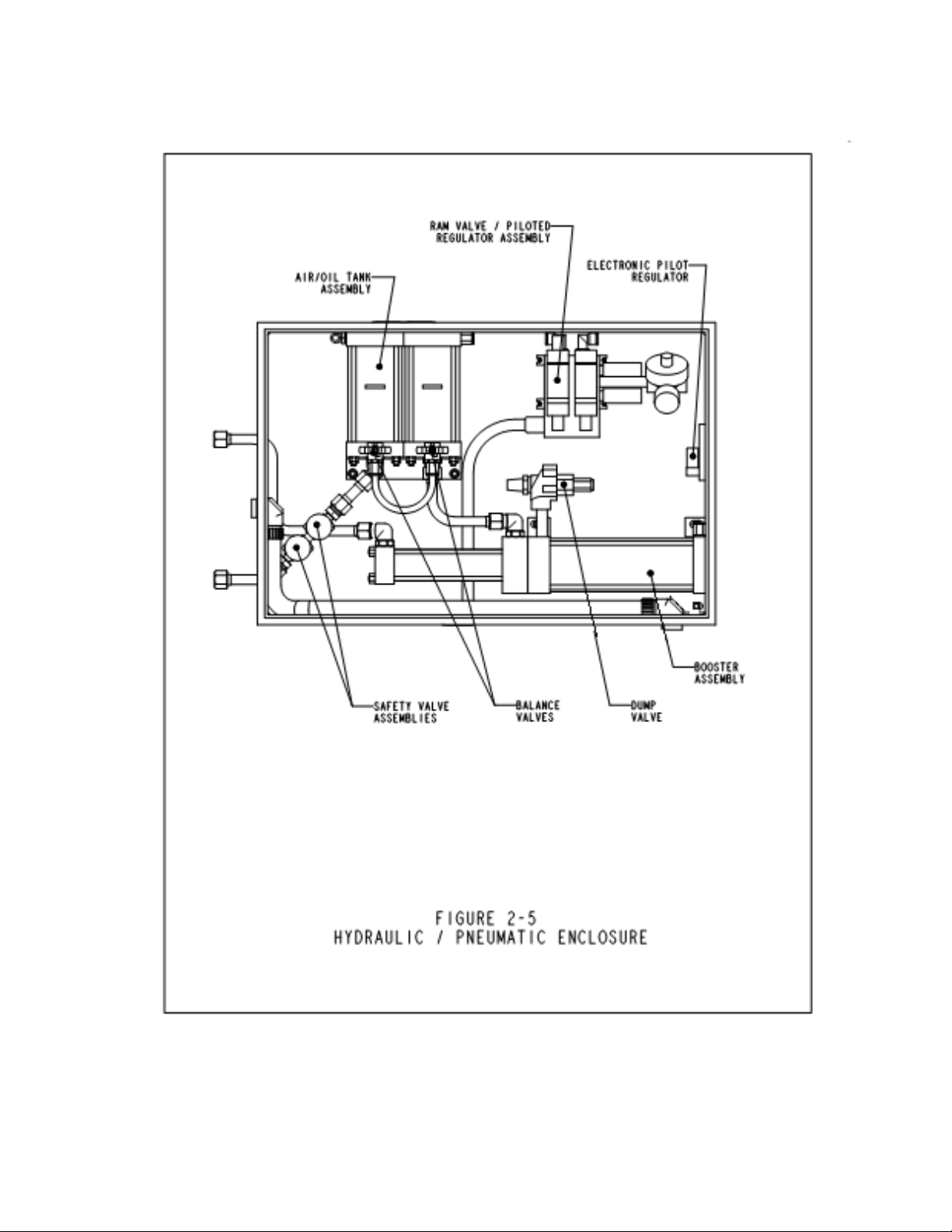
Pneumatic/Hydraulic Enclosure
The Pneumatic/Hydraulic Enclosure on the right side of the press houses all the major
components of the Air-Oil System that control the main cylinder. These components include the
computer controlled pressure regulator system, the ram valve assembly which includes the ram
valve and the booster valve, the Air-over-Oil tanks, the Air-Oil booster, and the hydraulic safety
valves.
Electrical Enclosure
The Electrical Enclosure, under the Pneumatic/Hydraulic Enclosure, houses the computer control
system (PLC) and various electrical components and distribution terminals. Electric Power and
the Foot Pedal connect to this enclosure. The door is key-locked and located on the back is the
electrical on-off switch. This switch must be ON for the press to be powered on. Turning off
this switch removes all power to the press. The electrical power cord plugs in next to the switch.
Removing the power cord can be used to lock out all power to press when performing
maintenance.
Copyright 2016 by PennEngineering®
7 of 119

Vibratory Feeder Bowl (Automatic Fastener Feeding Component)
The Vibratory Feeder Bowl, on the left side of the press, is used for automatic feeding of
fasteners. It is an electrically driven device, which holds and moves different types of fasteners.
Various types of tooling components are attached to the bowl to orient the fasteners being fed out
of the bowl. The vibratory bowl comes equipped with a "Universal Escapement" adapter, which
is used for all nut-type tooling and some stud-type tooling. The Vibratory Feeder Bowl is
controlled by a dial and a switch on the Bowl Control Box, above the bowl.
• Bowl Amplitude Dial - The bowl's amplitude or force of vibration is regulated by a dial
control. The amplitude adjustment is used to control the feed rate and performance of the
automatic feeding process.
• Bowl Three Mode Switch - A 3 position switch is used to select whether the bowl is always
on, always off or automatically controlled by the PLC. When the switch is set to auto, the
PLC turns on the bowl during run mode and during diagnostics. During run mode the PLC
will turn the bowl off if there is a period of inactivity. The PLC will restart the bowl
automatically when the next fastener is fed. When loading or unloading fasteners , turn the
bowl ON/OFF as desired. Return the switch to AUTO when finished.
Shuttle Support Assembly (Automatic Fastener Feeding Component)
The Shuttle Support Assembly located next to the Vibratory Feeder Bowl is used to hold and
actuate tooling shuttle components, route air supplies and hold the Stud-in-tube-Sensor and
"Puffer" Flow Control Valve. The Shuttle Air Cylinder on the Shuttle Support Assembly
actuates tooling shuttles. The shuttle receives the parts fed from the vibratory feeder bowl,
singulates the parts and feeds them out to the punch/anvil area. The Shuttle Support Assembly is
aligned with the vibratory feeder bowl. Proper alignment is important to the functioning of the
shuttle tooling.
• Stud-in-tube Sensor - The PLC uses this ring sensor to monitor and control the feeding
process of stud-type tooling.
• Puffer Flow Control Valve - This valve controls the air flow to the Vibratory Feeder Bowl
tooling attachments and is used to regulate various aspects of the escapement and nutgate
performance.
Copyright 2016 by PennEngineering®
8 of 119

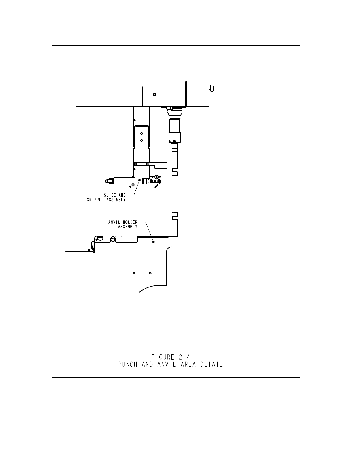
Slide and Gripper Assembly (Automatic Fastener Feeding Component)
The Slide and Gripper Assembly mounted to the top of the frame throat is used to hold top-feed
tooling components and has two pneumatic actuators. The two actuators are a linear slide
cylinder and a parallel acting gripper. The gripper is used to actuate the tooling jaws that hold
fasteners. The gripper opens and closes to receive and release fasteners. The gripper is attached
to the end of the linear slide. The linear slide is used to move the gripper and jaws from its
retracted position out to the punch position. This system is used to feed fasteners out to tooling
punches. The Slide and Gripper Assembly also holds tube extension tooling for stud-type
tooling. The Slide and Gripper Assembly can be removed for special workpiece accessibility.
Anvil holder Assembly
The Anvil Holder Assembly mounted to the bottom of the frame throat is used to hold the anvil
tooling components and has a single air cylinder. The Bottom Feed Cylinder is used to actuate
Bottom Feed Nut Tooling Modules.
Tooling Valve/Storage Enclosure
The Tooling Valve/Storage Enclosure is located underneath the Vibratory Feeder Bowl. Behind
the door is another enclosure that contains the pneumatic valves that control the different tooling
actuators and blowers. Under that enclosure is the Tooling Air Accumulation Tank. The tank
provides a steady supply of compressed air to the tooling valves for consistent tooling feeding
performance.
Air Supply Inlet System
The supply of compressed air enters the press in the back through a system, which includes a
filter/regulator and an electrically controlled quick exhaust/supply valve. The regulator is
manually set to control the supply line pressure. Turning on the quick exhaust/supply valve
supplies air to the press. When the quick exhaust/supply valve is turned off the valve closes and
exhausts all downstream compressed air in the press quickly.
Tooling Storage Cabinet (Optional)
The Tooling Storage cabinet is located on the left side of the press.
Copyright 2016 by PennEngineering®
9 of 119
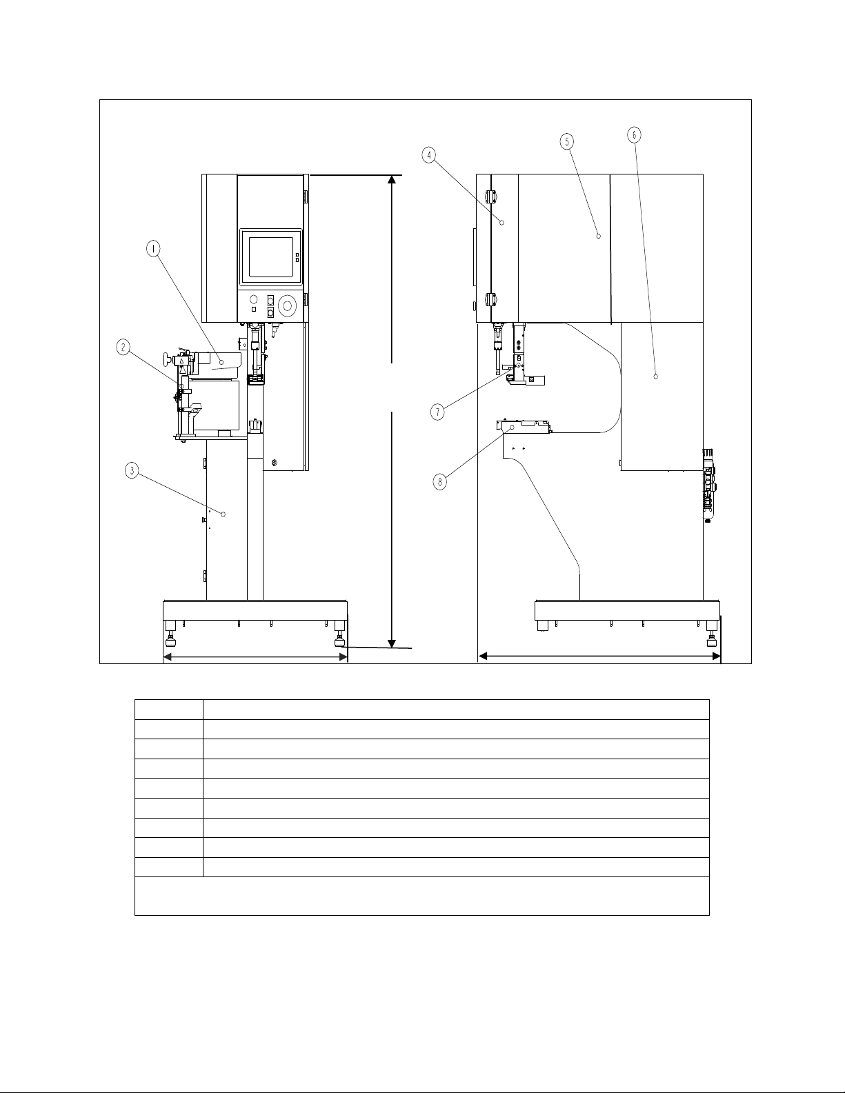
92cm (
36
inch)
126cm(
49.5
inch)
193cm
(76inch)
ITEM DESCRIPTION
1 VIBRATORY FEEDER BOWL
2 SHUTTLE SUPPORT ASSEMBLY
3 TOOLING VALVE/STORAGE ENCLOSURE
4 MAIN CYLINDER ENCLOSURE
5 PNEUMATIC / HYDRAULIC ENCLOSURE
6 ELECTRICAL ENCLOSURE
7 SLIDE AND GRIPPER ASSEMBLY
8 ANVIL HOLDER ASSEMBLY
FIGURE 2-1
SERIES 2000 PRESS
Copyright 2016 by PennEngineering®
10 of 119
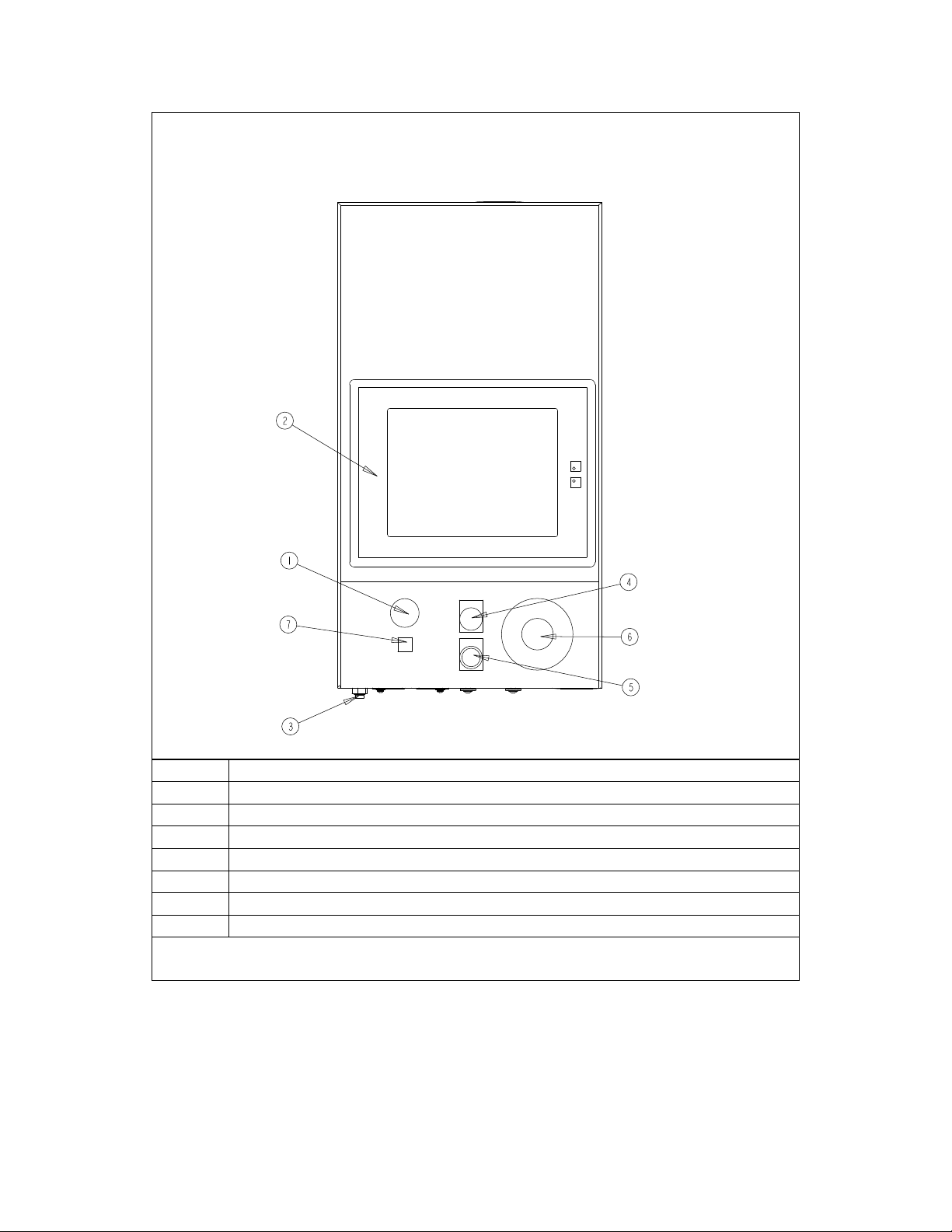
ITEM DESCRIPTION
1 AUDIBLE BEEPER
2 TOUCH SCREEN
3 VACUUM PORT
4 POWER “OFF” BUTTON
5 POWER “ON” BUTTON
6 E-STOP BUTTON
7 SPOTTING LIGHT ON/OFF BUTTON
FIGURE 2-2
OPERATOR CONTROLS
Copyright 2016 by PennEngineering®
11 of 119
Copyright 2016 by PennEngineering®
12 of 119
Copyright 2016 by PennEngineering®
13 of 119
Copyright 2016 by PennEngineering®
14 of 119

SECTION 3
SAFETY SYSTEM OPERATION
WARNINGS - To avoid injury:
1. Always shut off the electrical power, and remove the power cord, before servicing this
machine.
2. Only authorized and trained personnel should maintain, repair, setup, or operate this
equipment.
3. Always use eye protection when operating or maintaining the press.
SYSTEM SAFETY FEATURES
1. Shutting off the electrical power, with either the “OFF” push-button, the ON / OFF switch, or
pushing the E-Stop button, will cause the electric quick exhaust/supply valve to exhaust all
air pressure in the press. WITHOUT ANY CONTAINED PRESSURE, ALL PNEUMATIC
MOTION STOPS.
2. The electrical cabinet door is key-locked to discourage unauthorized access.
3. The patented safety system can distinguish between a work piece properly set-up between the
ram and the anvil, and a foreign object placed between the ram and the anvil. The safety
system operates as follows:
• A sensor called a linear transducer is installed on the top of the main cylinder. The linear
transducer senses the position of the main cylinder piston and transmits that information
back to the PLC.
• A device called the "safety assembly" is installed in the bottom of the ram. The assembly
consists of a fixed section called the housing and a compressible spring-loaded section
called the adapter. The adapter holds the punch tooling. When the ram extends and the
adapter or punch tooling contacts an object, the safety assembly compresses.
• Two redundant pairs of optical thru-beam sensors are located inside the front enclosure,
under the main cylinder. Each pair of sensors maintains an individual optical beam path
that is reflected through one of two holes in the ram by the "reflective collar". When the
safety assembly is compressed, part of the safety assembly inside the ram, blocks both
beam paths and the sensors are triggered.
• When the sensors are triggered, because, either the safety assembly is compressed, the
reflective collar is moved, or the beam path is blocked in some other way, the PLC
immediately senses the change.
Copyright 2016 by PennEngineering®
15 of 119

• During a Setup Cycle, the PLC uses this system to "learn" where the fastener and
workpiece location is by moving the ram down, compressing the safety assembly, sensing
the contact and reading the Linear Transducer. The data of the contact location is saved
and used for a comparison during each press/run cycle.
• During Press Cycling, the PLC determines each time it senses that the safety
assembly/punch has contacted something, whether it is "legitimate" or "not legitimate".
A "safety window" is used to allow for minor variations with workpiece or operator
precision.
• Only if BOTH redundant signals agree and the latest contact point is within the "safety
window", does the PLC allow the safety assembly to fully compress and for the air-oil
system to apply the predetermined high force needed for fastener installation.
4. Three levels of access security are available, each with a different four digit pass code
WARNING: Immediately upon receipt of your press, establish a “Maintenance
Code” for your supervisor/maintenance personnel only, as it is possible, however
difficult, to operate the press without the standard safeguards in place in the
Maintenance Mode. Only trained personnel should use the Maintenance Mode the
PennEngineering® is not responsible for improper maintenance mode procedures
which result in a loss of operation of the press or operator safety.
5. If the Linear Transducer or either of the ram safety sensors should develop an open or a
shortfault, the entire system, including the ram, will come to an immediate stop and not
operate further, until repairs are made.
Copyright 2016 by PennEngineering®
16 of 119

SECTION 4
PRESS INSTALLATION
Moving The Press
• When using a forklift or pallet jack be sure that the forks are properly located between the
fork guide tabs under the base of the press. When hoisting from above (See Fig 4-1), be sure
to balance the chain or strap between the two eyebolts to prevent swinging.
WARNING: unbalanced loading of the press or sudden stops may lead to toppling of the
press.
Locating The Press
• Select a well-lit clean area with a (relatively) level floor. The floor must be able to support
the weight of the press.
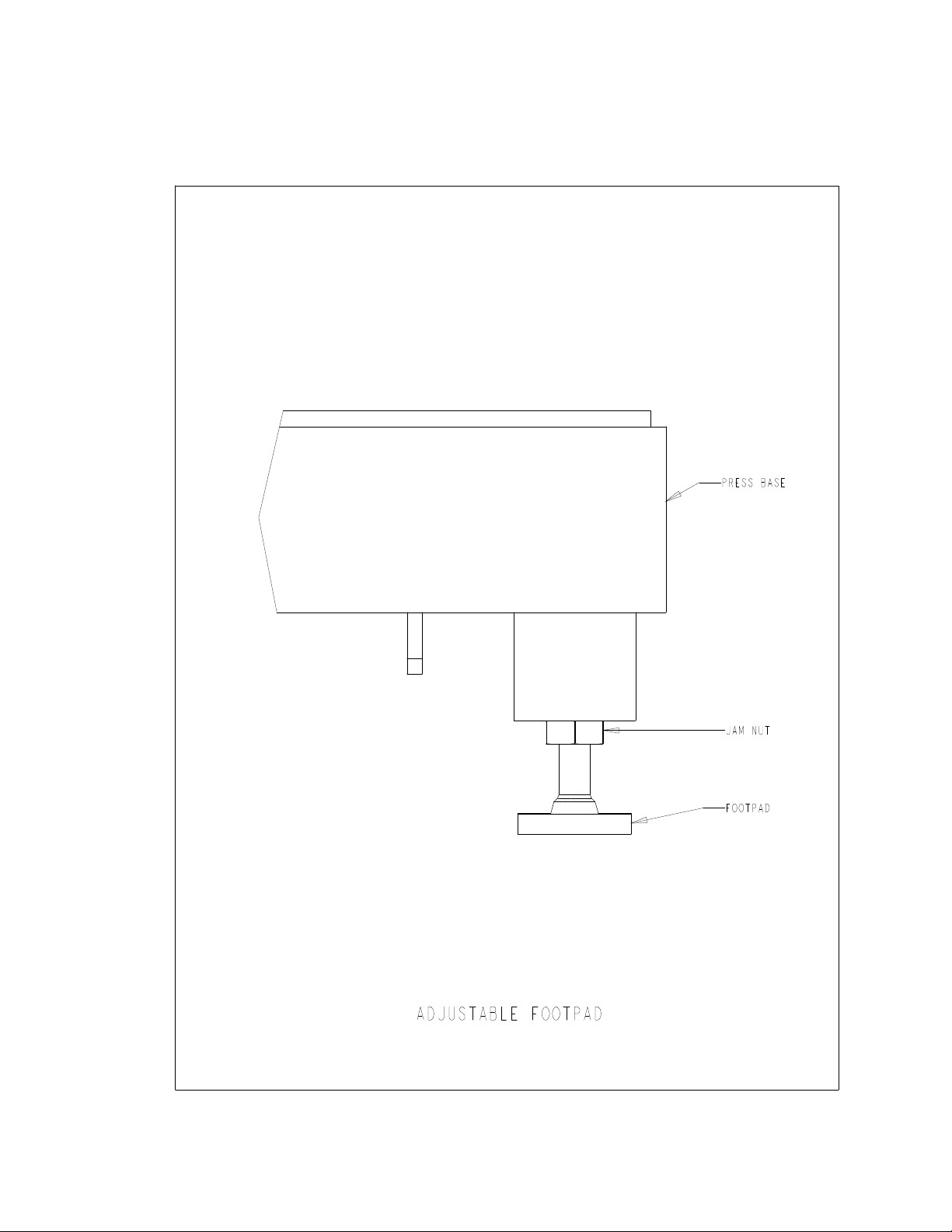
Leveling The Press
• The press should be leveled and stabilized after it has been located. This is done by adjusting
the height of each footpad then locking each footpad in position by tightening a jam nut. This
task requires two 3/4” wrenches (See Fig 4-2). An adjustable wrench may also be used.
Adjust the foot pad while reading the level at the tooling nut gate adapter. The universal
escapement adapter must sit level for proper functioning of the feed systems.
Open Space Requirements
• PennEngineering® has no specific requirements for providing open space around the
perimeter of a press. However, be sure to comply with any national or regional safety codes
that may dictate otherwise. For example, In the US the National Electrical Code requires that
there be at least thirty-six inches of clearance in front of the electrical enclosure. We do
recommend that you at least leave enough space around the press so the various storage and
maintenance enclosures can be opened fully and so the largest workpieces can be
accommodated.
Original Installation Requirements
After the final installation of the press verify the continuity of the protective bonding circuit
(TN-System) in accordance with EN 60204-1 Clause 18.2.2 standards.
Copyright 2016 by PennEngineering®
17 of 119
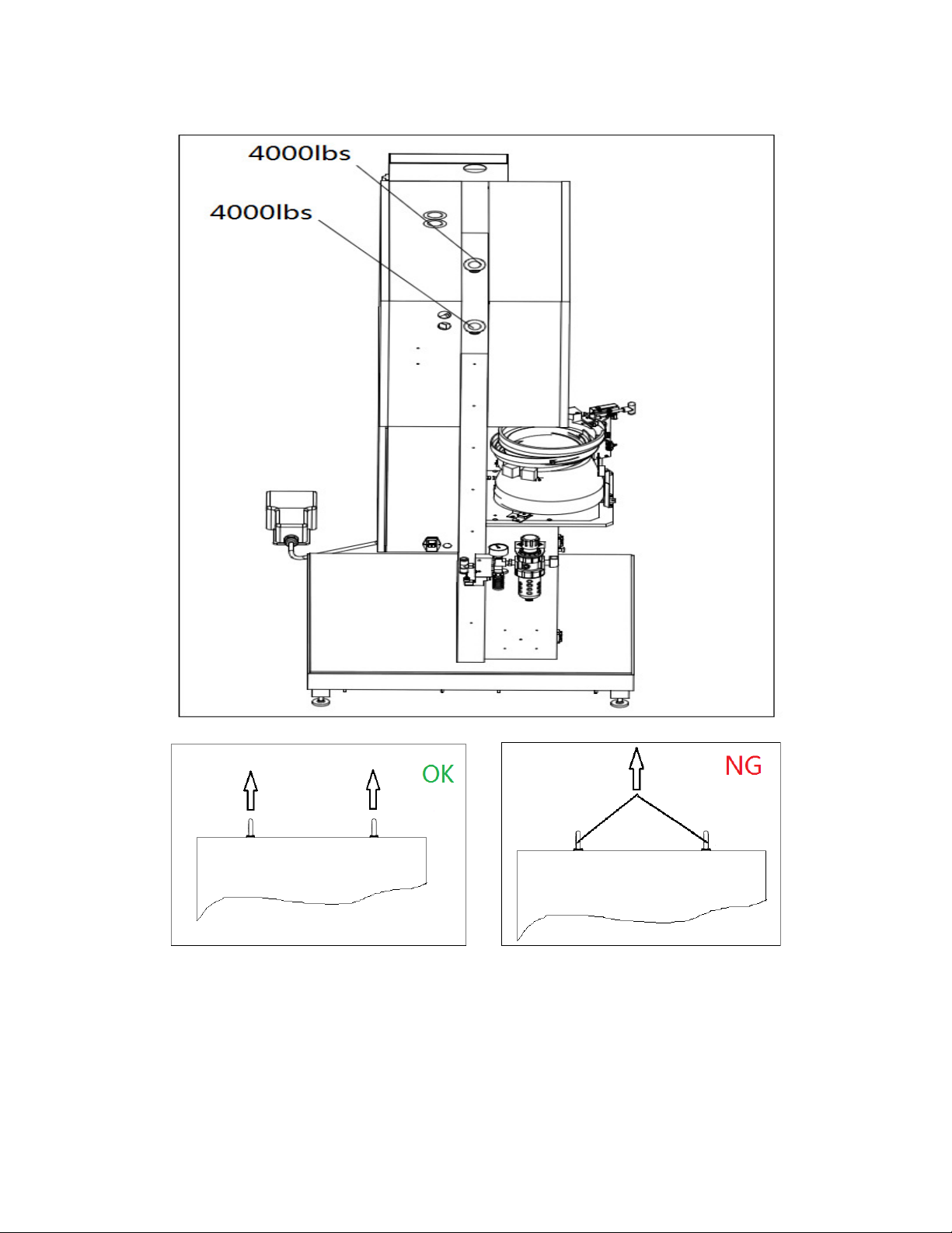
FIGURE4-1 Cable Suspension Diagram
Copyright 2016 by PennEngineering®
18 of 119
2
FIGURE 4 - 2
Copyright 2016 by PennEngineering®
19 of 119

Recommended Air Supply Hook-Up Arrangement
Proper air supply is very important to the performance and maintenance of the press. Following
these simple guidelines will ensure good press performance.
• Air Quality - The quality of the air supply is very important. The air must be clean and dry.
Moisture and debris will contaminate the oil and valve systems and lead to press performance
and maintenance problems.
• Air Supply Flow - Use a minimum 12mm (1/2”) inside diameter line and fittings from the
compressed air source to the press. Shop pressure ranging between 6 to 7 BAR (90 psi to
100 psi) is acceptable. Inadequate air flow will affect press performance.
• Air Consumption - Air consumption in automatic mode is about 4.5 liters of compressed air
per cycle. Average air consumption running at 20 KN (4500 Lbf) at 30 insertions per minute
is about 7 liters/sec at 1 atm. (15 Scfm). Air Supply Flow requirements are higher than these
values as air is only being consumed for half the time of each cycle.
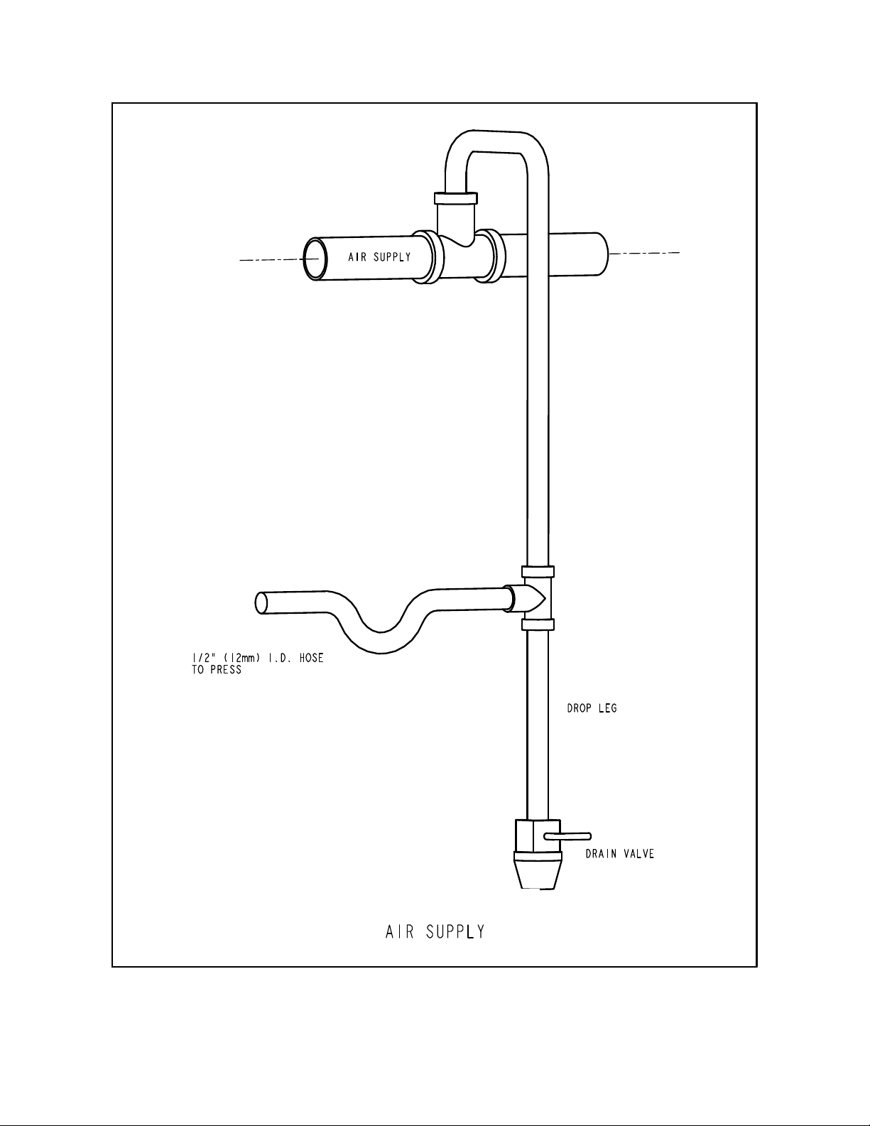
• Piping Installation – Proper piping hookup will help achieve the above requirements. See
figure 4-3 on the next page.
Connect to your supply line with a pipe pointing upwards that curves over and down. This
arrangement will help prevent water and compressor oil from entering the press.
Connect to that drop with your supply fitting for a 12mm (1/2”) or larger hose.
Continue the end of the drop to a drain valve. This will help collect additional water and oil
and allow the system to be purged.
If your factory air supply falls short of the above recommendations, an air reservoir tank of
an appropriate size for your location can be used.
An auxiliary filter/separator installed immediately outside the machine is recommended.
Install An Appropriate Power Cord.
• The press is equipped with a Male IEC 320/CEE22 Universal Connector for power. Outside
North America, unless special arrangements have been made, a customer supplied power
cord must be installed. No other electrical system modifications are necessary. Connection
should be in accordance with your local electrical code.
Install The Foot Switch
• Plug the foot switch into the receptacle located at the lower left corner of the front of the
electrical enclosure.
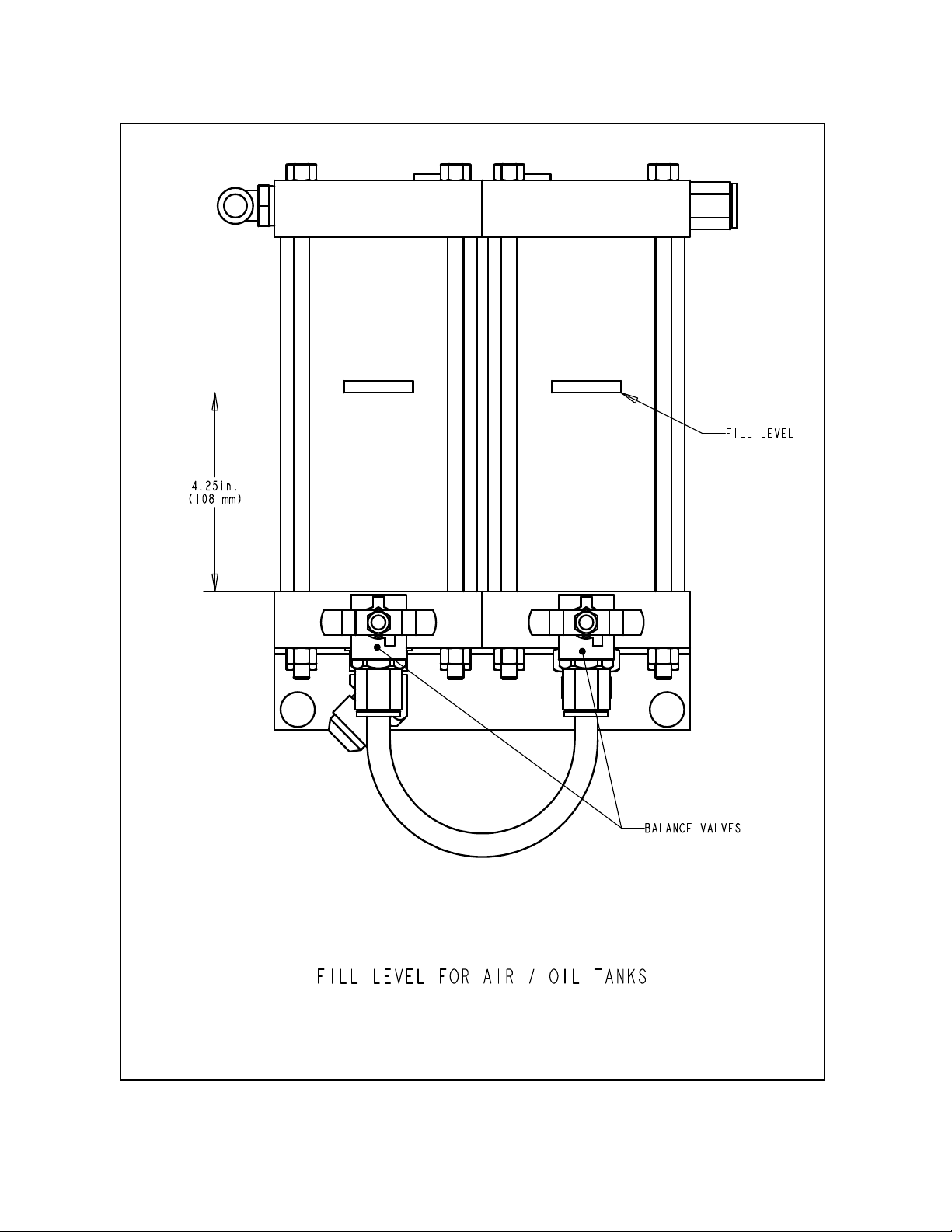
Check The Hydraulic Fluid Level In Both Air-Oil Tanks
• Check to be sure the hydraulic fluid is level with, but not over, the fill lines on the air-oil
tanks. If the fluid level is too high or too low correct the problem by following the procedures
provided in section eleven of this manual.
Copyright 2016 by PennEngineering®
20 of 119
Copyright 2016 by PennEngineering®
21 of 119
Copyright 2016 by PennEngineering®
22 of 119

SECTION 5
GENERAL FUNCTION DESCRIPTIONS
System Function:
The function of a PEMSERTER
SERIES 2000
FASTENER INSTALLATION PRESS is
to safely, quickly and consistently install PEM brand self-clinching fasteners in various types of
sheet material. To do this the press uses:
• A patented point-of-operation safety system that controls the descent of the ram and does not
allow the ram to descend if it contacts any object other than the intended fastener and
workpiece.
• Automatic fastener feeding system that locates the fastener at the point of insertion, so that
the operator is free to handle just the workpiece.
• Air-oil-booster system that provides quick ram travel with high installation forces at the point
of insertion.
• Precise installation tools and computer controlled installation forces.
Self-clinching Fastener Installations:
PEM self-clinching fasteners are installed into punched or drilled holes in ductile sheet
material. To install a PEM self-clinching fastener:
• The shank of the fastener is placed into the installation hole until the part of the fastener that
is larger than the hole called the displacer (such as the knurls for nuts, or the head for
standoffs) sits on the edge of the hole.
• A parallel squeezing force is applied to press the displacer (overhanging part) of the fastener
into the sheet material.
• The force causes the sheet material to cold flow into the undercut of the fastener that is
between the displacer and the shank. This traps the fastener within the sheet metal.
Copyright 2016 by PennEngineering®
23 of 119

Setting up the Press:
The following section of the manual describes the setup process in general. For details on setting
up and operating the press see the appropriate section in the manual.
Step 1 - Setup Tooling
Tooling setup consists of selecting appropriate tooling for the fastener being fed and the
workpiece, installing the tooling on the press and adjusting the feed controls.
Different types of tooling that feed the same size fastener are selected for accessing
different shapes and sizes of work pieces.
See the Tooling Section of this manual on selecting the right tooling.
Step 2 - Select the Setup for the Tooling and Fastener on the Touchscreen
Once the tooling is installed, the next step is to setup the press by using the touchscreen.
The touchscreen setup is simple and can be done one of three ways.
• New Tool Set-up – Choose tooling mode, fastener size and workpiece material.
• Recall A Job – Select from a previously programmed Job stored in the press
• Recall Last Job – Run the same Job that was just run, the press remembers, even if it is
turned off between jobs.
See the Touchscreen Controls section of this manual on choosing the right selections for
setup.
When the selections are complete, the press automatically sets the values for operation
and moves onto safety setup.
Step 3 - Safety Setup
The next step is very quick and simple but very important.
Safety Setup is the step where the press learns the position of installation called the
Safety Set point. The operator positions the materials for an installation, but the press
does not actually install the fastener. The ram extends and touches the fastener and
workpiece. The touch point teaches the press where the proper installation point should
be. The Press is ready to install fasteners.
Copyright 2016 by PennEngineering®
24 of 119

Fastener Automatic Feed Functions:
Automatic Fastener Feeding is done from the vibratory feeder bowl to the insertion point in the
workpiece. The following steps are taken:
• The vibratory feeder bowl moves the fasteners around the bowl and past a tooling component
called a nutgate for nut-type tooling or an escapement for stud-type tooling.
• The fasteners are oriented in the tooling and fed into a tooling shuttle. The shuttle takes the
first fastener and separates it from the rest. That fastener is blown with compressed air out of
the shuttle into a plastic tube that leads to the punch and anvil area.
• Depending on the type of tooling the fastener is either fed directly into a tooling module like
a stud-injector module or bottom feed nut module or into a set of jaws on the top feed slide
and gripper system.
• During a top-feed tooling installation, the fastener is picked up from the jaws either by a
vacuum punch or pin punch and the jaws open and pull back.
• The workpiece is placed with the installation hole onto either a fastener or tooling guide pin.
When the operator has located the workpiece, the foot pedal can be depressed to begin the
installation process.
Installation Process:
• When the foot pedal is depressed, the ram extends down quickly bringing the punch to the
workpiece.
• When the fastener contacts the workpiece the safety sensors are tripped. The Press Control
System checks that the position called the insertion point, is at the same position as the
learned position at setup, the safety set point. Only if the insertion point is within a certain
range of the safety set point, does the installation proceed.
• If the insertion point is good then the high installation force is applied to install the fastener
and the ram returns up.
Copyright 2016 by PennEngineering®
25 of 119

Special Features and Conditions:
• Dwell/Force Verification (Quality Assurance System) – Dwell time is the period of time
from when the press control system starts the high force cycle to when the high force cycle ends.
The Dwell software system monitors pressure feedback signals throughout the cycle to assure a
quality installation.
• Soft Touch Mode – When running in Soft Touch Mode the press will slow down just before
contacting the workpiece and fastener. This mode is slightly slower, but can insure against
damage to soft and brittle work pieces.
• Interrupted Mode – When running in Interrupted Mode the press will slow down and stop
upon contacting the workpiece and fastener. This mode is the ultimate in assurance just before
installation that a workpiece or layers of work pieces are properly aligned.
• Setpoint Tolerance – Can be selected for Standard Tolerance or Narrow Tolerance. Narrow
Set point Tolerance sets a smaller range for the allowed deviation of each installation from the
Safety Set point. Narrow Tolerance is used for smaller fasteners and more precise operations to
assure proper installation in the workpiece hole. This mode is less tolerant of work pieces not
held level and poor hole quality or hole debris.
• Start at Minimum Setup – This mode changes the setup sequence. Instead of pre-selecting a
force at setup, the press interrupts the dwell time of the first installation and allows the operator
to adjust the force as the fastener is being installed. This function allows for the most precise
installation force setup. Once the installation force is established, it can be saved within one of
the Recall Job memory locations.
• Fastener Length Monitoring (FLM) – This mode requires optional tooling hardware to be
installed. During the automatic fastener feeding process for long fasteners such as stud and long
standoffs, the length of each fastener is checked to insure that it is the correct length. If a
fastener is too long or short, it is rejected and not installed. During shop operation, fasteners of
different lengths can become mixed. Long fastener tooling is typically designed to accept
various lengths of fasteners to increase the value of the tooling and decrease the costs of
installing different size fasteners. FLM Hardware and Software can be setup to check for any
length fastener.
• Safety Fault Error - If the difference between the insertion point and the safety set point is
outside the range of the set point tolerance then a safety fault error condition occurs. When a
safety fault occurs the redundant safety valves close, immediately stopping downward ram
motion. The ram reverses direction and retracts the punch. The safety assembly on the end of the
ram never fully compresses and the boost cycle is never initiated.
Copyright 2016 by PennEngineering®
26 of 119
 Loading...