

Page 1
CONVERSION INSTRUCTIONS
LP TO NATURAL GAS (SEA LEVEL TO 2000 FEET)
Cast Iron Gas Fired Water Boilers
15B, UH15B, BWB, GMGWB
For Forced Hot Water
!
WARNING
This conversion kit shall be installed by a qualied
service agency in accordance with the manufacturer’s
instructions and all applicable codes and requirements
of the authority having jurisdiction. If the information
in these instructions is not followed exactly, a re,
an explosion or production of carbon monoxide may
result causing property damage, personal injury or
loss of life. The qualied service agency is responsible
for the proper installation of this kit. The installation
is not proper and complete until the operation of the
converted appliance is checked as specied in the
manufacturer’s instructions supplied with the kit.
Tools Required
Flat Head Screwdriver, 1/4” Nut Driver, 7/16” Open Ended
Wrench, 3/16” Allen Wrench, 18” Manometer (or dial
manometer)
Installation
1.
Turn off gas supply to the boiler.
!
WARNING
Electrical shock hazard. Turn OFF electrical power
supply at service panel before making electrical
connections. Failure to do so could result in death
or serious injury.
KIT CONTENTS
ITEM QTY.
Installation Instructions 1
Conversion Plate/Label 1
Pilot Orice - Spark 1
Pilot Orice - 24 Volt 1
Liquid Sealing Compound 1
Spring Kit 1
PILOT ORIFICES
MFG. PART NUMBER
Honeywell 390686-4*
*Use 390686-37 for Boilers Manufactured before July
2008 with Q381 Pilot.
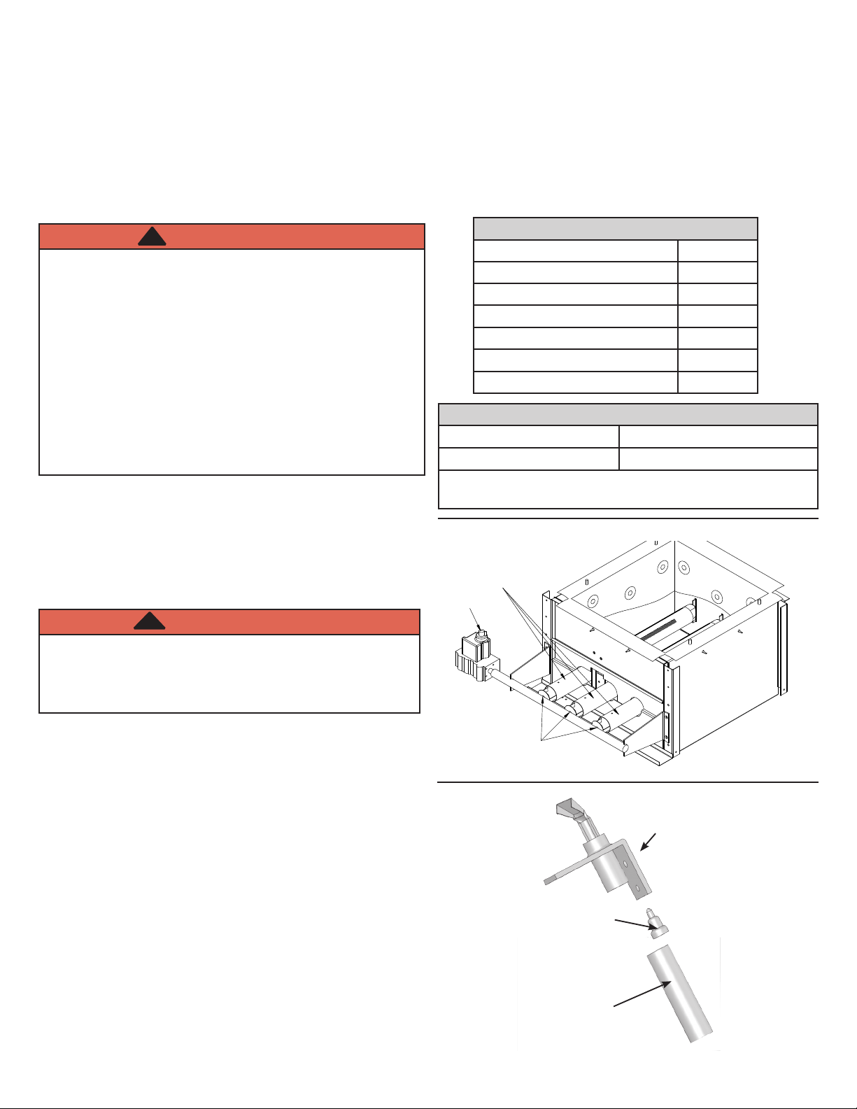
Figure 1
BURNERS
GAS VALVE
KNOB
2.
Turn off all electrical to boiler.
3.
Remove front panel.
4.
Remove burner access door.
5.
Remove main gas burner tubes. See Figure 1.
6.
Remove main burner orices. See Figure 1.
7.
Install supplied natural gas main burner orices. See
table for orice size and quantities.
8.
Use 7/16” wrench, disconnect pilot tube from pilot. See
Figure 2.
9.
Remove pilot orice. See Figure 2.
10.
Install natural gas pilot orice. See Figure 2.
11.
Apply liquid sealing compound to threads of pilot
assembly tting.
12.
Attach pilot tube to pilot and securely tighten. See
Figure 2.
13.
Replace LP main burner tubes, if present, with natural
gas tubes. See Figure 3.
ORIFICES
Figure 2
Pilot
Pilot Orice
Pilot Tube
P/N 24004820, Rev. E [11/2014]
Page 2
LP TO NATURAL GAS CONVERSION INSTRUCTIONS
-X
LP
ONLY
NAT/LP
14.
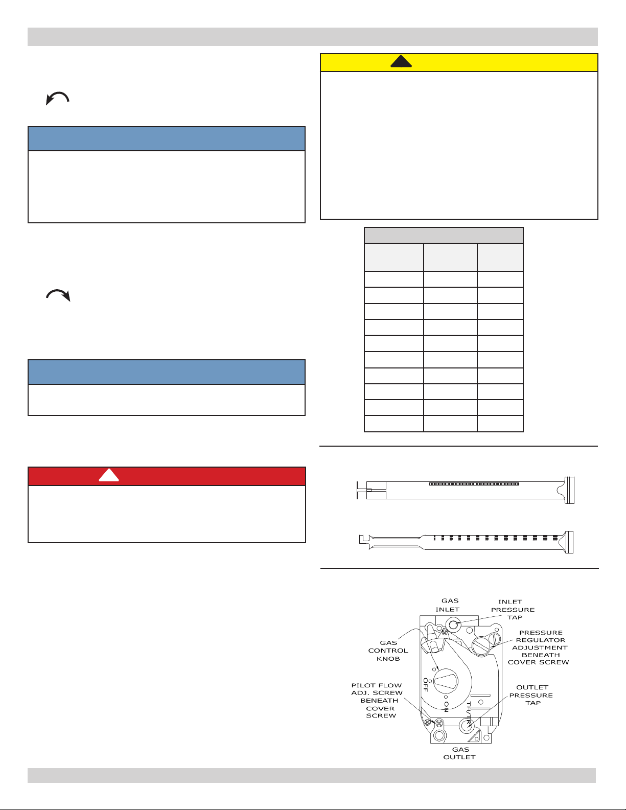
Remove the cover screw from gas valve pressure regulator. See Figure 4.
15.
Remove adjustment screw by turning counterclockwise
. See Figure 5.
16.
Remove red LP gas spring. See Figure 5.
NOTICE
Parts for steps 17, 18, 26, and 27 are located in the
Honeywell natural gas conversion kit HW#394588
(#VG00802) for VR8200, VR8204, VR8300 or
VR8304 gas valve or conversion kit HW#391936
(#VG00701) for VR8440 gas valve.
!
CAUTION
WHAT TO DO IF YOU SMELL GAS
• Do not try to light any appliance.
• Do not touch any electrical switch; do not use
any phone in your building.
• Immediately call your gas supplier from a
neighbor’s phone. Follow gas supplier’s
instructions.
• If you cannot reach your gas supplier, call the re
department.
17.
Insert stainless steel natural gas spring. See Figure 5.
18.
Install adjustment screw. Verify screw top is ush with
regulator top.
19.
Turn pressure regulator adjustment screw clockwise
eight (8) complete turns. This is starting point
for manifold pressure.
20.
Install manometer to pressure tap on outlet side of gas
valve. See Figure 4.
21.
Turn ON electric and gas supply.
NOTICE
Verify gas inlet pressure is between minimum of 5”
w.c. maximum of 14” w.c.
22.
Check for gas leaks around all gas connections using
commercially available soap solution specically made
for leak detection.
!
DANGER
Fire Hazard. Do not use matches, candles, open
ames, or other methods providing ignition source.
Failure to comply will result in death or serious
injury.
MAIN BURNER ORIFICES
INPUT
(Btuh)
45,000 3.1 1
70,000 2.8 2
96,000 3.2 2
120,000 2.9 3
145,000 3.2 3
170,000 2.9 4
175,000 3.0 4
195,000 3.2 4
245,000 3.2 5
295,000 3.2 6
Figure 3 - Burners
ORIFICE
(mm)
QTY.
23.
With boiler operating adjust manifold pressure to 3½”
water column by turning pressure regulator adjustment
screw.
24.
Turn OFF electric and gas supply.
25.
Remove manometer. Replace pressure tap cover screw
securely.
26.
Install silver natural gas regulator adjustment cover
screw with o-ring. See Figure 5.
27.
Mount conversion label on gas valve.
28.
Turn electric and gas supply ON.
29.
Cycle boiler to ensure proper operation and lighting.
30.
Replace front panel.
31.
Fill out and afx conversion plate adjacent to
rating plate. Complete this step to provide proper
identication for customer service or technical support
issues.
Figure 4 - Gas Valve
2
Page 3

SEQUENCE OF OPERATION
Figure 5 - Gas Valve
Figure 6 - Burners, Gas Valve, & Manifold
• Thermostat actuates on call for heat, completing circuit
to control.
• Completed circuit to control activates circulator. Damper
will close end switch inside the damper. This will
complete circuit to ignition system and ignition takes
place.
• Power is interrupted between control system and
ignition system if boiler water temperature exceeds high
limit setting on boiler mounted high limit control. Power
remains off until boiler water temperature drops below
high limit setting. Circulator continues to operate under
this condition until thermostat is satised.
• Blocked ow of combustion products through boiler
venting system causes blocked vent safety switch to
shut main burner gas off. If boiler ueway becomes
blocked, ame rollout safety switch will shut main
burner gas off. See Figure 6. If either condition occurs,
do not attempt to place boiler back into operation.
Contact qualied service agency.
• Main burner ame should have well dened inner blue
mantel with lighter blue outer mantel. See Figure 7.
• Pilot ame should envelop ⅜ to ½ inch of tip of the pilot
thermocouple, ignition/sensing electrode or mercury
sensor. See Figure 8.
Figure 7 - Burner with Mantel
Checking Gas Input Rate To Boiler
• Adjust gas input to boiler by removing protective cap on
pressure regulator and turning screw clockwise to
increase input and counterclockwise to decrease
input.
• Set natural gas manifold pressure at approximately
3.5 inches water column. Manifold pressure is taken at
outlet side of gas valve.
• To check for proper ow of natural gas to boiler, divide
input rate shown on rating plate by heating value of gas
obtained from local gas company. This will determine
number of cubic feet of gas required per hour.
• With all other gas appliances off, determine ow of gas
through meter for two minutes and multiply by 30 to
get hourly rate. Make minor adjustments to gas input as
described above.
• Change burner orices if nal manifold pressure varies
more than plus or minus 0.3 inches water column from
specied pressure.
• Primary air adjustment is not necessary, therefore air
shutters are not furnished as standard equipment. Air
shutters are available on request where required by
local codes or conditions.
3
Page 4

Figure 8 - Pilot
3/8” To 1/2”
In Flame
LP TO NATURAL GAS CONVERSION INSTRUCTIONS
Ignition
Electrode
 Loading...