

Pennco 15B045FE User Manual
15B SERIES II
Models
15B045FE
15B070FE
15B096FE
15B120FE
15B145FE
15B170FE
15B195FE
15B245FE
15B295FE
Cast Iron Gas Fired Boilers
For Forced Hot Water
INSTALLATION, OPERATION &
MAINTENANCE MANUAL
An ISO 9001-2008 Certified Company
C.S.A. Certied
For Natural Gas Or Propane
Tested For 100 psi
ASME
Working Pressure
Manufactured by:
ECR International, Inc.
2201 Dwyer Avenue,
Utica NY 13501
web site: www.ecrinternational.com
P/N 240009024, Rev. E [10/2014]

TABLE OF CONTENTS
1 - Ratings & Data - Natural Gas & Propane Gas ...........................................................4
2 - Dimensions .............................................................................................................5
3 - Installation Procedure ............................................................................................6
4 - Ventilation & Combustion Air ..................................................................................7
5 - Connecting Supply & Return Piping .........................................................................8
6 - Vent Installation ...................................................................................................14
7 - Vent System Modication ......................................................................................14
8 - Vent Damper Installation & Instructions ...............................................................15
9 - Connecting Gas Service .........................................................................................16
10 - Electrical Section .................................................................................................17
11 - Wiring Diagram ...................................................................................................18
12 - Lighting Instructions ...........................................................................................21
13 - Normal Sequence Of Operation ...........................................................................22
14 - General Instructions ...........................................................................................22
15 - Checking Gas Input Rate To Boiler ......................................................................24
Appendix A - Control Module ..................................................................................... 25
A.1 Installation Environment Considerations ................................................................ 25
A.2 Electrical Connections ......................................................................................... 25
A.3 Adjusting Settings .............................................................................................. 25
A.4 Display ............................................................................................................. 25
A.5 Operation .......................................................................................................... 26
A.6 Boiler High Limit Temperature Controller ................................................................ 27
A.8 Troubleshooting Error Codes ................................................................................ 27
A.9 Intermittent Pilot Ignition System Verication ......................................................... 28
2
SAFETY MESSAGES
IMPORTANT: Read the following instructions
COMPLETELY before installing!!
Safety Symbols & Warnings
The following dened symbols are used throughout this
manual to notify the reader of potential hazards of varying
risk levels.
DANGER
!
Indicates a hazardous situation which, if not avoided,
WILL result in death or serious injury
!
WARNING
Indicates a hazardous situation which, if not avoided,
could result in death or serious injury.
!
CAUTION
Indicates a hazardous situation which, if not avoided,
could result in minor or moderate injury.
NOTICE
Used to address practices not related to personal
injury.
KEEP THIS MANUAL NEAR BOILER
RETAIN FOR FUTURE REFERENCE
WARNING
!
Fire, explosion, asphyxiation and electrical shock
hazard. Improper installation could result in death
or serious injury. Read this manual and understand
all requirements before beginning installation.
WARNING
!
Keep boiler area clear and free from combustible
materials, gasoline and other ammable vapors
and liquids.
DO NOT obstruct air openings to the boiler room.
Modication, substitution or elimination of factory
equipped, supplied or specied components may
result in personal injury or loss of life.
TO THE OWNER - Installation and service of this
boiler must be performed by a qualied installer.
TO THE INSTALLER - Leave all instructions with
boiler for future reference.
When this product is installed in the
Commonwealth of Massachusetts the installation
must be performed by a Licensed Plumber or
Licensed Gas Fitter.
3
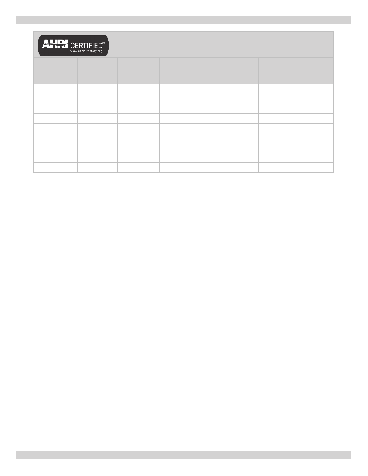
1 - RATINGS & DATA - NATURAL GAS & PROPANE GAS
Model No.
Input
Mbh
(1)
Table 1
Heating
Capacity
Mbh
- Ratings and Capacities
(1)
Net AHRI
Rating Water
Mbh
(2)
**
AFUE Elect.
Ign.
No. Of
Burners
Recommended Air
Cushion Tank
(3)
Water
Content
(Gals.)
15B045 45 37 32 82.0% 1 15 2.4
15B070 70 57 50 82.0% 2 15 4.0
15B096 96 79 69 82.0% 2 30 4.0
15B120 120 98 85 82.0% 3 30 5.6
15B145 145 119 103 82.0% 3 30 5.6
15B170 170 140 122 82.0% 4 30 7.2
15B195 195 160 139 82.0% 4 30 7.2
15B245 245 201 174 82.0% 5 30 8.8
15B295 295 242 210 82.0% 6 60 10.4
EXPLANATORY NOTES
-- All boilers are design certied for installation on noncombustible oor.
-- Recommended chimney height 20 feet. In special cases where conditions permit, chimney height may be
reduced to 10 feet. Refer to the latest revision of NFGC part 11.
-- Electric service to be 120 Volts, 15 Amps, 60 Hz.
-- The MEA number for the this boiler is 19-79-E.
(1) Input rating for sea level to 2,000 ft. (610m) above sea level.
United States, over 2000 ft (610m) above sea level. Reduce input rate 4% for every 1,000 ft (304m) above sea
level.
(2) Net AHRI Water Ratings shown based on piping and pickup allowance of 1.15. Consult manufacturer before selecting
boiler for installations having unusual piping and pickup requirements, such as intermittent system operation,
extensive piping systems, etc.
For forced hot water systems where boiler and all piping within area to be heated, boiler may be selected on basis of
its heating capacity.
(3) Tank sized for non-ferrous baseboard or radiant panel systems. Increase size for cast iron baseboard and
radiation.
STANDARD EQUIPMENT: Boiler Jacket, Cast Iron Boiler Battery, High Limit Control, Intermittent Electric Ignition Pilot
System, Vent Damper Relay, Circulator With Return Piping To Boiler, Main Gas Burners, Gas Control (Includes Automatic Gas
Valve, Gas Pressure Regulator, Intermittent Pilot, Safety Shutoff, Pilot Flow Adjustment, Pilot Filter), A.S.M.E. Relief Valve, Drain
Valve, Spill Switch, Rollout Switch, Combination Gas Control, Automatic Vent Damper. Not Shown Are: Wiring Harness,, Nonlinting Safety Pilot.
4
**
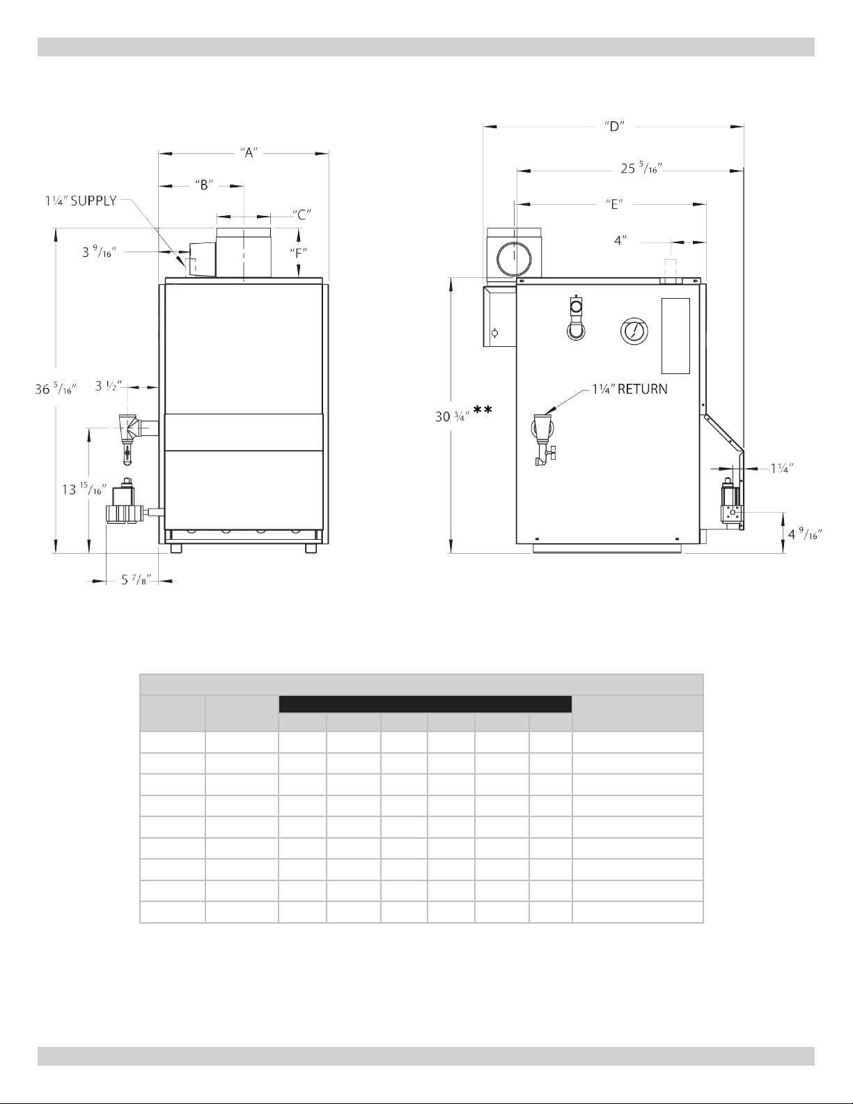
Dimensions
2 - DIMENSIONS
Table 2 - Dimensions
Model No.
Natural Gas
Inlet*
A B C D E F
15B045 ½" 11¼ 5⅝ 4 27⅛ 207/
Dimensions (Inches)
415/
16
15B070 ½" 15⅛ 7 5 28⅛ 2015/16415/
15B096 ½" 15⅛ 7 5 28⅛ 2015/16415/
15B120 ½" 19 9½ 6 29⅛ 217/1657/
15B145 ½" 19 9½ 6 29⅛ 217/1657/
15B170 ½" 22⅞ 113/
15B195 ½" 22⅞ 113/
15B245 ¾” 26¾ 136/
15B295 ¾” 30⅝ 155/
* Propane Gas Inlet (All Units) 1/2”
7 30⅛ 2115/16515/
16
7 30⅛ 2115/16515/
16
8 31⅛ 227/16615/
16
9 32⅛ 2215/16815/
16
** Minimum height for Low Water Cutoff installation.
5
Pump Size Supply &
Return Tappings
16
16
16
16
16
16
16
16
16
1¼"
1¼"
1¼"
1¼"
1¼"
1¼"
1¼"
1¼"
1¼"

TABLE OF CONTENTS
1 - Ratings & Data - Natural Gas & Propane Gas ...........................................................2
2 - Dimensions .............................................................................................................3
3 - Installation Procedure ............................................................................................6
4 - Ventilation & Combustion Air ..................................................................................7
5 - Connecting Supply & Return Piping .........................................................................8
6 - Vent Installation ...................................................................................................14
7 - Vent System Modication ......................................................................................14
8 - Vent Damper Installation & Instructions ...............................................................15
9 - Connecting Gas Service .........................................................................................16
10 - Electrical Section .................................................................................................17
11 - Wiring Diagram ...................................................................................................18
12 - Lighting Instructions ...........................................................................................20
13 - Normal Sequence Of Operation ...........................................................................21
14 - General Instructions ...........................................................................................21
15 - Checking Gas Input Rate To Boiler ......................................................................23
Appendix A - Control Module ..................................................................................... 24
A.1 Installation Environment Considerations ................................................................ 24
A.2 Electrical Connections ......................................................................................... 24
A.3 Adjusting Settings .............................................................................................. 24
A.4 Display ............................................................................................................. 24
A.5 Operation .......................................................................................................... 25
A.6 Boiler High Limit Temperature Controller ................................................................ 26
A.7 Troubleshooting.................................................................................................. 26
A.8 Troubleshooting Error Codes ................................................................................ 26
A.9 Intermittent Pilot Ignition System Verication ......................................................... 27
6

SAFETY MESSAGES
IMPORTANT: Read the following instructions
COMPLETELY before installing!!
Safety Symbols & Warnings
The following dened symbols are used throughout this
manual to notify the reader of potential hazards of varying
risk levels.
!
DANGER
Indicates a hazardous situation which, if not avoided,
WILL result in death or serious injury
!
WARNING
Indicates a hazardous situation which, if not avoided,
could result in death or serious injury.
!
CAUTION
Indicates a hazardous situation which, if not avoided,
could result in minor or moderate injury.
NOTICE
Used to address practices not related to personal
injury.
KEEP THIS MANUAL NEAR BOILER
RETAIN FOR FUTURE REFERENCE
WARNING
!
Fire, explosion, asphyxiation and electrical shock
hazard. Improper installation could result in death
or serious injury. Read this manual and understand
all requirements before beginning installation.
!
WARNING
Keep boiler area clear and free from combustible
materials, gasoline and other ammable vapors
and liquids.
DO NOT obstruct air openings to the boiler room.
Modication, substitution or elimination of factory
equipped, supplied or specied components may
result in personal injury or loss of life.
TO THE OWNER - Installation and service of this
boiler must be performed by a qualied installer.
TO THE INSTALLER - Leave all instructions with
boiler for future reference.
When this product is installed in the
Commonwealth of Massachusetts the installation
must be performed by a Licensed Plumber or
Licensed Gas Fitter.
7
3 - INSTALLATION PROCEDURE
!
WARNING
Improper installation, adjustment, alteration, service
or maintenance could result in death or serious
injury.
1.
Installation must conform to the requirements of the
authority having jurisdiction or, in the absence of such
requirements, to the National Fuel Gas Code, ANSI
Z223.1/NFPA 54, and/or Natural Gas and Propane
Installation Code, CAN/CSA B149.1.
2.
Where required by authority having jurisdiction,
installation must conform to the Standard for Controls
and Safety Devices for Automatically red Boilers,
ANSI/ASME CSD-1.
3.
Boiler series is classied as a Category I. Vent
installation shall be in accordance with "Venting of
Equipment ," of the National Fuel Gas Code, ANSI
Z223.1/NFPA 54, or "Venting Systems and Air Supply
for Appliances," of the Natural Gas and Propane
Installation Code, CAN/CSA B149.1, or applicable
provisions of the local building codes.
4.
Boiler has met safe lighting and other performance
criteria with gas manifold and control assembly on
boiler per latest revision of ANSI Z21.13/CGA 4.9.
5.
Boiler shall be installed such that gas ignition system
components are protected from water (dripping,
spraying, rain, etc.) during appliance operation and
service, (circulator replacement, condensate trap,
control replacement, etc.).
6.
Locate boiler on level, solid base as near chimney as
possible and centrally located with respect to heat
distribution system as practical.
7.
Allow 24 inches (610mm) at front and right side for
servicing and cleaning.
8.
When installed in utility room, door should be wide
enough to allow largest boiler part to enter, or to
permit replacement of another appliance such as water
heater.
!
WARNING
Fire hazard. Do not install boiler on combustible
ooring or carpeting. Failure to follow these
instructions could result in death or serious injury.
9.
FOR INSTALLATION ON NON-COMBUSTIBLE
FLOORS ONLY - For installation on combustible
ooring special base must be used. (See Replacement
Parts Section.) Boiler can not be installed on
carpeting. Minimum clearances to combustible
construction are:
TOP ....................................18 IN. (457mm)
FRONT .........................................ALCOVE *
FLUE CONNECTOR ................. 6 IN. (152mm)
REAR....................................8 IN. (229mm)
CONTROL SIDE ................... ..9 IN. (76mm)
OTHER SIDE............................3 IN. (76mm)
HOT WATER PIPING ................. 2 IN. (51mm)
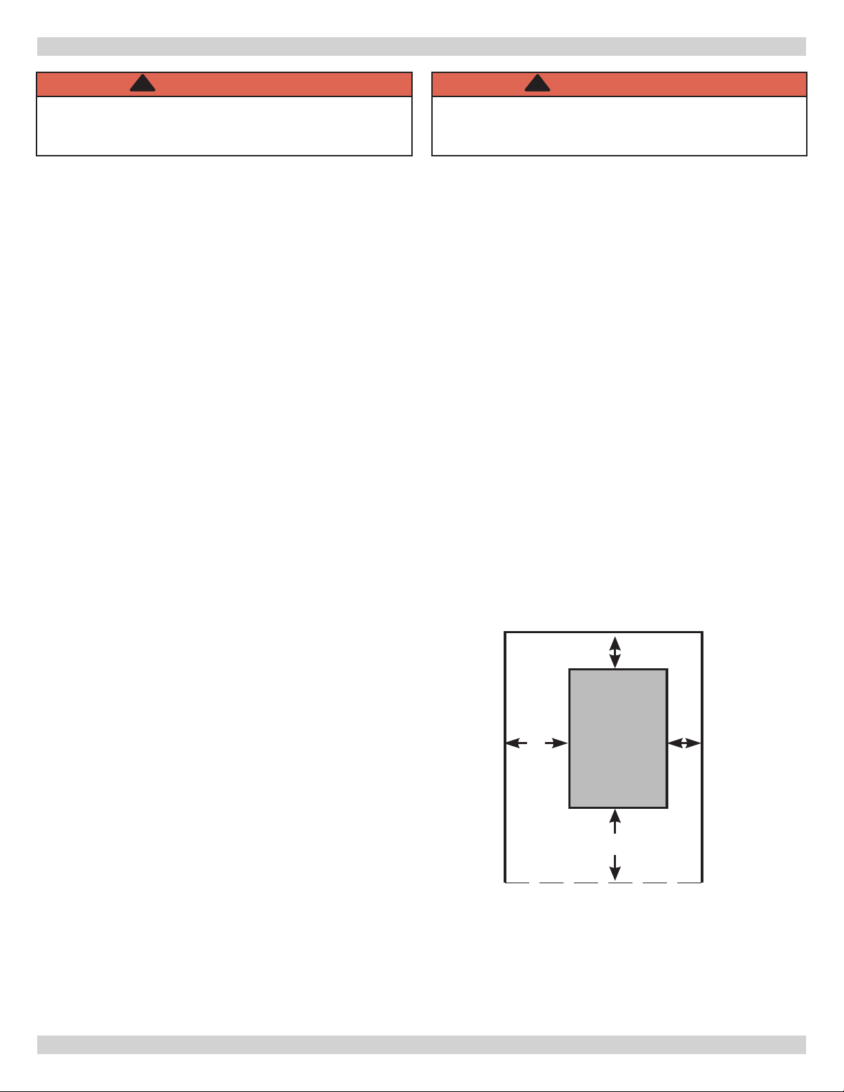
NOTE: Greater clearances for access should supersede fire
protection clearances.
* Denition of Alcove is three sided space with no wall in
front of boiler. ANSI standard for alcove is 18 inches from
front of appliance to leading edge of side walls as shown
below.
Minimum Clearances To Combustible
Construction (As Seen From Above)
8"
3"
9"
Control
Side
BOILER
8
18"
Front

4 - VENTILATION & COMBUSTION AIR
Provide combustion air and ventilation air in accordance
with the section “Air for Combustion and Ventilation,” of the
National Fuel Gas Code, ANSI Z223.1/NFPA 54, or Sections
8.2, 8.3 or 8.4 of Natural Gas and Propane Installation
Code, CAN/CSA B149.1, or applicable provisions of local
building codes.
Provide make-up air where exhaust fans, clothes dryers,
and kitchen ventilation equipment interfere with proper
operation.
National Fuel Gas Code recognizes several methods
of obtaining adequate ventilation and combustion air.
Requirements of the authority having jurisdiction may
override these methods.
• Engineered Installations. Must be approved by
authority having jurisdictions.
• Mechanical Air Supply. Provide minimum of 0.35
cfm per Mbh for all appliances located within space.
Additional requirements where exhaust fans installed.
Interlock each appliance to mechanical air supply
system to prevent main burner operation when
mechanical air supply system not operating.
• All Indoor Air. Calculate minimum volume for all
appliances in space. Use a different method if
minimum volume not available.
о Standard Method. Cannot be used if known air
inltration rate is less than 0.40 air changes per
hour. See Table 3 for space with boiler only. Use
equation for multiple appliances.
Volume ≥ 50 ft3 x Total Input [Mbh]
о Known Air Inltration Rate. See Table 3 for
space with boiler only. Use equation for multiple
appliances. Do not use an air inltration rate
(ACH) greater than 0.60.
Volume ≥ 21 ft3/ACH x Total Input [Mbh]
о Refer to National Fuel Gas Code for opening
requirements between connection indoor spaces.
National Gas and Propane Installation Code Requires
providing air supply in accordance with:
• All Outdoor Air. Provide permanent opening(s)
communicating directly or by ducts with outdoors.
о Two Permanent Opening Method. Provide opening
commencing within 12 inches of top and second
opening commencing within 12 inches of bottom
enclosure.
Direct communication with outdoors or
communicating through vertical ducts. Provide
minimum free area of 1 in2 per 4 Mbh of total
input rating of all appliances in enclosure.
Communicating through horizontal ducts.
Provide minimum free area of 1 in2 per 2
Mbh of total input rating of all appliances in
enclosure.
о One Permanent Opening Method. Provide opening
commencing within 12 inches of top of enclosure.
Provide minimum clearance of 1 inch on sides
and back and 6 inches on front of boiler (does not
supersede clearance to combustible materials).
о Combination Indoor and Outdoor Air. Refer to
National Fuel Gas Code for additional requirements
for louvers, grilles, screens and air ducts.
• Combination Indoor and Outdoor Air. Refer to
National Fuel Gas Code for application information.
• Section 8.2 and 8.3 when combination of appliances
has a total input of up to and including 400 Mbh (120
kW).
• Section 8.4 when combination of appliances has total
input exceeding 400 Mbh (120 kW).
• Refer to Natural Gas and Propane Installation Code
for specic air supply requirements for enclosure
or structure where boiler is installed, including air
supply openings and ducts.
Table 1 - Minimum Room Volume, Indoor Air Only*
Input Mbh
45 2250 9450 4725 3150 2363 1890 1575
70 3500 14700 7350 4900 3675 2940 2450
96 4800 20160 10080 6720 5040 4032 3360
120 6000 25200 12600 8400 6300 5040 4200
145 7250 30450 15225 10150 7613 6090 5075
170 8500 35700 17850 11900 8925 7140 5950
195 9750 40950 20475 13650 10238 8190 6825
245 12250 51450 25725 17150 12863 10290 8575
295 14750 61950 30975 20650 15488 12390 10325
* Table values based on boiler only. Add volume for any additional appliances.
Standard
Method
0.1 0.2 0.3 0.4 0.5 0.6
Known Air Inltration Rate Method (Air Changes Per Hour)
9
5 - CONNECTING SUPPLY & RETURN PIPING
!
WARNING
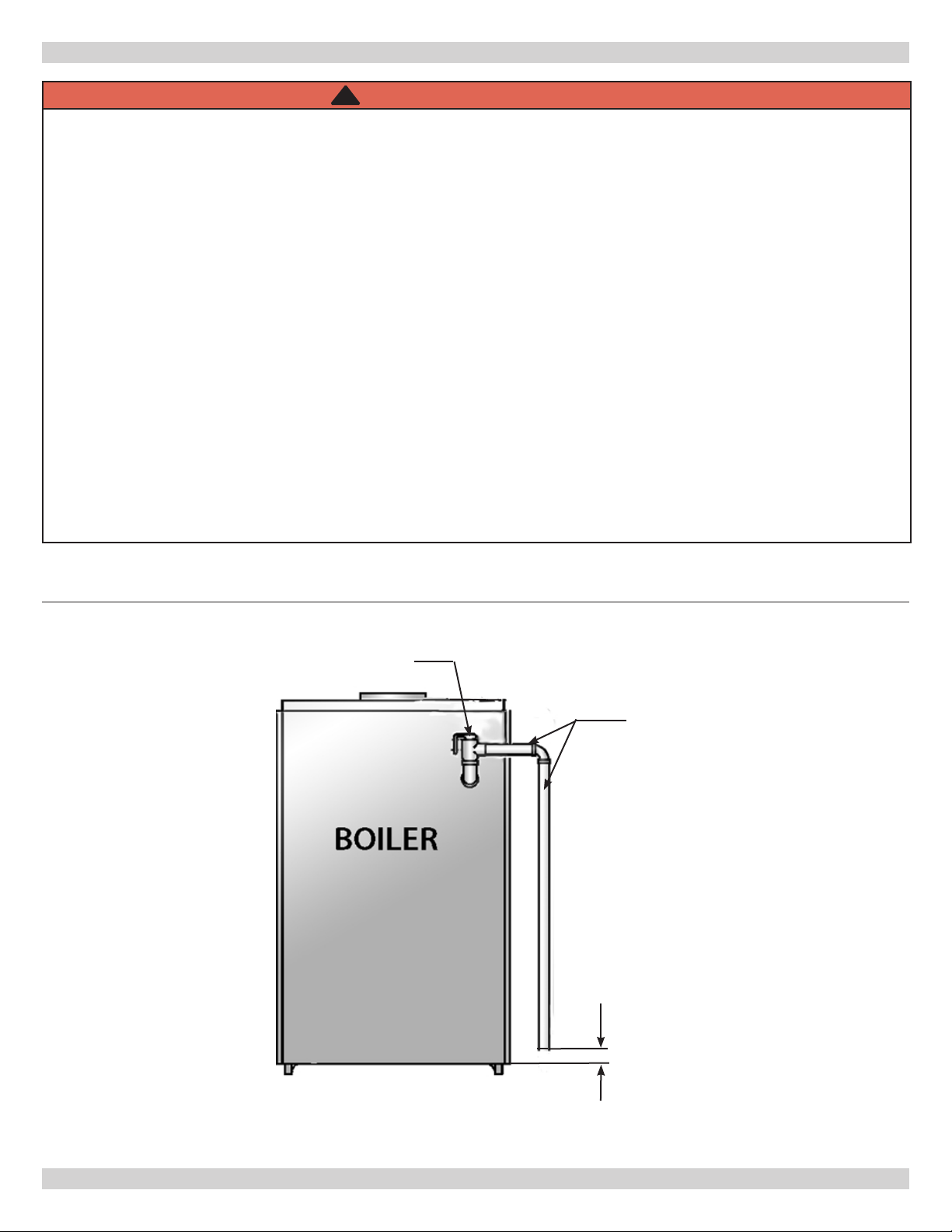
Burn or Scald Hazard. Discharge line shall be installed to relief valve outlet connection to avoid burns,
scalding, or water damage due to discharge of steam and/or hot water during operation.
Discharge line shall:
• connect to relief valve outlet and piped down to safe point of disposal. Check local codes for maximum
distance from oor or allowable safe point of discharge.
• be of pipe size equal to or greater than that of the relief valve outlet over the entire length of discharge
line;
• have no intervening shutoff valve between safety relief valve and discharge to atmosphere (do not plug or
place any obstruction in discharge line.
• terminate freely to atmosphere where any discharge will be clearly visible and at no risk of freezing;
• allow complete drainage of the valve and the discharge line;
• be independently supported and securely anchored to avoid applied stress on the relief valve;
• be as short and straight as possible;
• terminate with plain end (not threaded);
• be constructed of material suitable for exposure to temperatures of 375° F (191°C); or greater.
Refer to local codes and appropriate ASME Boiler and Pressure Vessel Code for additional installation
requirements.
Figure 1 - Safety Relief Valve
Safety Relief Valve
Discharge Line
Check local codes
for maximum
distance from oor
or allowable safe
point of discharge.
10
 Loading...