


System 450 Series Modular Controls Product
Bulletin
LIT-12011458
2021-07-21
Introduction
The System 450™ is a family of modular, digital electronic
controls that you can assemble and set up to provide
reliable temperature, pressure, and humidity control for a
wide variety of HVAC, commercial, and industrial process
applications.
The System 450 control system replaces the System
350™ and System 27 control systems, and provides
additional features and benefits with fewer than 20 model
variations. The System 450 control modules provide a
field-configurable out-of-the-box solution. Most System
450 control modules can control temperature, pressure,
and humidity systems simultaneously.
You can set up a single C450 control module as a standalone control or to connect with expansion modules to
control up to 10 On/Off relay and proportional analog
outputs, based on any of the three available inputs.
Use the System 450 control modules with communications
to connect System 450 control systems to Modbus® or
Ethernet networks for remote monitoring and setup. The
Modbus communications control module is an RS485,
rooftop unit (RTU) compliant subordinate device. The
Ethernet communications control module has an integral
web server that can deliver web pages through a direct
connection, on your LAN, or across the internet.
The System 450 reset control modules provide many of
the features of the standard models for temperature
and humidity control. In addition, these modules provide
setpoint reset, real-time setback scheduling, and equal
run-time balancing capability.
The System 450 control module with hybrid analog output
has a single self-selecting analog output to optimize and
extend the controlled speed range of variable speed
electronically commutated (EC) motors.
Figure 1: System 450 Control System with control,
power, and expansion modules
Features and benefits
Durable, compact, interchangeable modular
components with plug-together connectors and DIN
rail or direct wall mount capability
Eliminate field wiring between modules and quickly and
easily design, assemble, install, and upgrade your control
systems.
Versatile, multipurpose, field-configurable control
modules and expansion modules designed for global
use
Create a wide variety of application-specific control
systems to control temperature, pressure, or humidity, or
all three conditions simultaneously, with only a small suite
of module models.
Control modules with bright backlit LCDs and fourbutton touchpad UIs, up to three hard-wired input
sensors, and up to 10 relay or analog outputs in any
combination for each control system
Provide a quick, clear, visual status of your System 450
control system inputs and outputs with the touch of a
button and quickly and easily set up and adjust your
control system.
Extensive suite of compatible temperature and
humidity sensors and pressure transducers
Monitor and control a wide range of HVAC and process
conditions in a variety of standard and global units of
measurement.
Differential control
Enables your control system to monitor and maintain a
temperature, pressure, or humidity differential between
two sensor points within a system, process, or space.
On/Off delays
Configure an on delay and an off delay to set the times
between a setpoint trip and the energizing or deenergizing of a relay.
C450Cxx, C450Rxx, C450Sxx, C450Yxx
Overview
The System 450 Series is a family of compact digital
electronic control, expansion, and power modules that
you can assemble and set up to provide reliable on/
off and proportional control of temperature, pressure,
and humidity conditions in a wide variety of HVAC,
commercial, and industrial process applications.
A System 450 Series control system includes the following
features:
• A single control module with LCD and 4-button
touchpad
• One to three inputs
• One to 10 relay or analog outputs provided by the
control module and expansion modules
• An optional power module
Compact modular plug-together design
All System 450 modules feature a compact, durable,
gray LEXAN® housing with DIN rail clips and slotted
mounting holes molded into the back of the housing for
easy installation.
The System 450 modules also feature 6-pin connectors on
the sides of the housing for easy assembly, upgrade of
your control systems, and to eliminate the need for field
wiring between modules.
A System 450 control system provides compact, clean, and
consistent control system assemblies that are simple to
build, install, and maintain.
Multipurpose and field-configurable design
The System 450 control, expansion, and power modules
are multipurpose devices that you can configure in the
field to control temperature, pressure, and humidity
simultaneously.
On/Off relay control
Relay outputs provide low and line-voltage on/off control
for devices and equipment in the controlled systems.
Each relay is a single-pole, double-throw (SPDT) set of dry
contacts.
Note: The System 450 output relays are SPDT dry
contact relays only and do not provide any power
source for the controlled equipment.
See Technical Specifications for output relay electrical
rating information. See Table 1 for information on the
System 450 control modules with this feature.
Analog proportional control
Analog outputs provide proportional analog signals for
devices and equipment in your controlled systems.
Each analog output can generate either a 4 mA to 20
mA or 0 VDC to 10 VDC signal. The output signal type is
self-selecting; after you connect the analog output to
the controlled equipment, the output detects the analog
input on the controlled equipment and generates the
appropriate analog signal for the connected input.
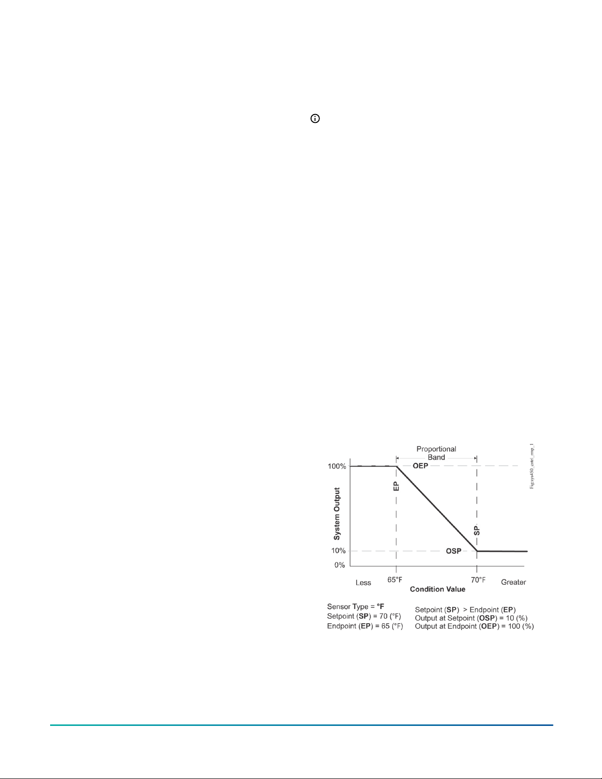
You can set up an analog output to generate a direct
acting or reverse acting proportional output signal. You
can also set up the output signal strength to increase
or decrease in either the direct acting or reverse acting
mode. See the example in Figure 4.
An analog output’s control action is automatically
determined by the setup values you select for the
setpoint, end point, % output at setpoint, and % output at
endpoint values when you set up the output in the UI.
A control ramp indicator appears on the output status
screen for each analog output to represent the analog
output’s control action.
Figure 2: Proportional analog output operation for
reverse acting room heating application
Global design
A System 450 control system is the next generation of
System 350 and System 27 modular controls.
The System 450 modular control system has fewer than
20 model variations and provides far more features and
flexibility than either the System 350 modular control
system with 54 models, or the System 27 modular control
system with 40 models.
The System 450 modules are designed, tested, and
certified for global application and are Underwriters’
Laboratories, Inc. (cULus) Listed and CE compliant.
You can set up the System 450 control systems in the
global standard units of measurement such as Fahrenheit,
Celsius, psi, bar, inches water column (in. W.C.), and
relative humidity (RH).
Control capabilities
The System 450 control system provides a variety of
control capabilities depending on the model you select.
See Table 1 for information on System 450 control
modules with specific features.
System 450 Series Modular Controls Product Bulletin2
See Table 1 for information on the System 450 control
modules with this feature.
Proportional plus integral control
In addition to standard proportional only control analog
signals, a System 450 control system provides integral
control capability and six time integral selections that
you can use to set up analog outputs to generate a
proportional plus integral signal.
Proportional plus integral (PI) control incorporates a
time-integral control action with proportional control
action. If correctly set up, a PI control loop can effectively
eliminate offset error and enable a controlled system to
drive much closer to the preferred setpoint, even under
large constant loads. On a properly sized system with
predictable loads, PI control can maintain the controlled
system very close to the setpoint.
The integration constant that you select establishes the
rate at which the control readjusts the analog output
signal. The faster the integration constant, the faster the
control readjusts the output signal, and the faster the
recovery rate of a properly sized and setup control loop.
See Table 1 for information on the System 450 control
modules with this feature.
Multistage On/Off and proportional control
You can set up multiple outputs to create a variety of
equipment staging control systems. Depending on the
control module and expansion modules, a System 450
multistage application may use On/Off control relay
outputs or proportional control analog outputs. See Table
1 for information on the System 450 control modules with
this feature.
High input signal select
The High Input Signal Selection feature enables a System
450 control system to monitor a temperature, pressure, or
humidity condition with two or three sensors of the same
type and control relay and analog outputs based on the
highest condition value sensed.
See Table 1 for information on the System 450 control
modules with this feature.
Differential control
The Differential Control feature enables a System 450
control system to monitor and maintain a temperature,
pressure, or humidity differential between two sensors
of the same type. This feature also enables the control
system to control relay outputs, analog outputs, or a
combination of relay and analog outputs, based on
the sensed differential value relative to user-selected
differential values. An example is the water pressure drop
across an in-line water filter. See Table 1 for information
on the System 450 control modules with this feature.
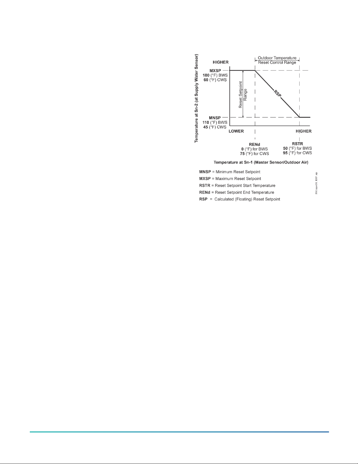
Reset control
The System 450 reset control modules automatically
adjust the setpoint for a supply control loop, based on
input from the outdoor or ambient master sensor and the
user-selected reset setpoint settings. This functions saves
energy by using only the required capacity of the supply
to heat, cool, dehumidify, or humidify the preferred space
or environment.
See Figure 3 for an example of Setpoint Reset Control for
both a chilled water temperature reset application and a
boiler water temperature reset application. See Table 1 for
information on the System 450 control modules with this
feature.
Figure 3: Reset setpoint application for boiler water
supply (BWS) and chiller water supply (CWS) showing
relationships between the reset
Setback scheduling
Use the reset control module’s real-time clock to schedule
outputs by day of week and time of day.
You can also set up setback temperatures and humidity
to create an occupied or unoccupied setback schedule
for the outputs in your control system. You can select a
negative setback value for heating or humidification, or
a positive setback value for cooling or dehumidification
control. See Table 1 for information on the System 450
control modules with this feature.
Run-time balancing
The reset control module’s run-time balancing feature
enables your control system to even out the runtimes of
staged equipment by automatically selecting the stage
with the smallest runtime when it responds to increases in
the system load.
Use run-time balancing to control up to four staged
outputs. See Table 1 for information on the System 450
control modules with this feature.
Analog output signal limiting
The analog output signal limiting feature on the System
450 control modules with communications reduces the
rate at which an analog output updates its output signal
strength in response to input signal changes.
When it controls a device such as a modulating actuator,
the analog output signal limiting feature can help
lengthen actuator life by reducing the actuator position
update frequency. The following parameters control this
feature:
• Output signal update rate: Select the rate in seconds
at which an analog output updates the output signal to
the controlled equipment
System 450 Series Modular Controls Product Bulletin 3
• Output signal dead band: Create a deadband for the
analog output signal within which the output signal
strength remains constant
See Table 1 for information on the System 450 control
modules with the analog output signal limiting feature.
Binary input control for relay outputs
A binary input is a user-supplied pair of dry contacts.
Connect a binary input to any of the three control module
input terminals and control the output relays in your
control system based on whether the binary input’s state
is open or closed. Examples of dry contacts include door
switches, timers, occupancy sensors, and other switching
devices.
A sensor set up as a binary input can be referenced
only by a relay output. Analog outputs cannot reference
sensors set up as binary inputs.
On/Off duration time control
Use the four time control parameters on the control
modules with communications to set up the relay outputs
with On or Off time delays and minimum On or Off times.
You can set each of the four On or Off duration control
parameters from 0 seconds to 300 seconds or 5 minutes,
in 1-second intervals.
Hybrid analog output control
The hybrid analog output control on C450CPW-400 control
modules enables an analog VDC output to transition to a
pulse output at low signal levels.
This function ensures more efficient low-speed control of
variable speed EC motors in condenser fan applications.
Network communications
The System 450 communications control modules provide
network connectivity and communications. Depending
on the communications control module, your controls
system can connect to and communicate over either
Ethernet networks or Modbus networks. See Table 1 for
information on the System 450 control modules with this
feature.
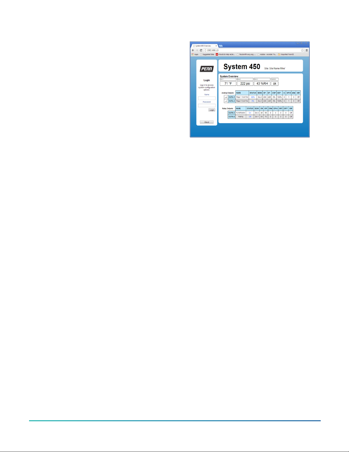
Ethernet communications
The System 450 control modules with Ethernet
communications have an integral web server that delivers
web pages to client browsers on desktop and laptop
computers, as well as smart phones, devices, and tablets.
Use the System 450 web UI to monitor your control
system status and set up or change the configuration
in simple, user-friendly web pages delivered to your
computer through a direct connection, a LAN connection,
or the internet.
Figure 4: System 450 System Overview page example
You can monitor control system status and configure the
control system parameters in both the local UI through
the LCD and four-button touchpad, and the web UI.
Use the System 450 control modules with Ethernet
communications to perform the following tasks:
• Directly connect your computer to the System 450
control module with an Ethernet cable, and set up,
monitor, and modify your control system
• Connect your control system to an existing network
and establish a static IP address or use a Dynamic Host
Configuration Protocol (DHCP) server to provide a
dynamic address
• Set up Dynamic Domain Name Server and browse to
your System 450 control system on a local network or
across the internet using a text-based host name URL
instead of a numeric IP address and port number
The System 450 web UI provides easy remote access to
your System 450 controls systems through your LAN or
the internet. Use the web UI to log on directly, locally, or
remotely and view the web UI system status, system setup
parameters, and parameter values in the UI.
Use the system configuration web pages to set up or
change the parameters for your system outputs in the
web UI. When the remote access lock feature is activated
in the web UI, users can view the control system status
but cannot make system changes.
RS485 Modbus communications
The System 450 control module with Modbus
communications is an RS485, RTU compliant Modbus
subordinate device. You can use it to connect your
System 450 control system to Modbus networks and
communicate over them.
The System 450 Modbus communication control module
also enables your entire control system to respond to data
requests and commands from a Modbus master device on
the Modbus network.
System 450 Series Modular Controls Product Bulletin4
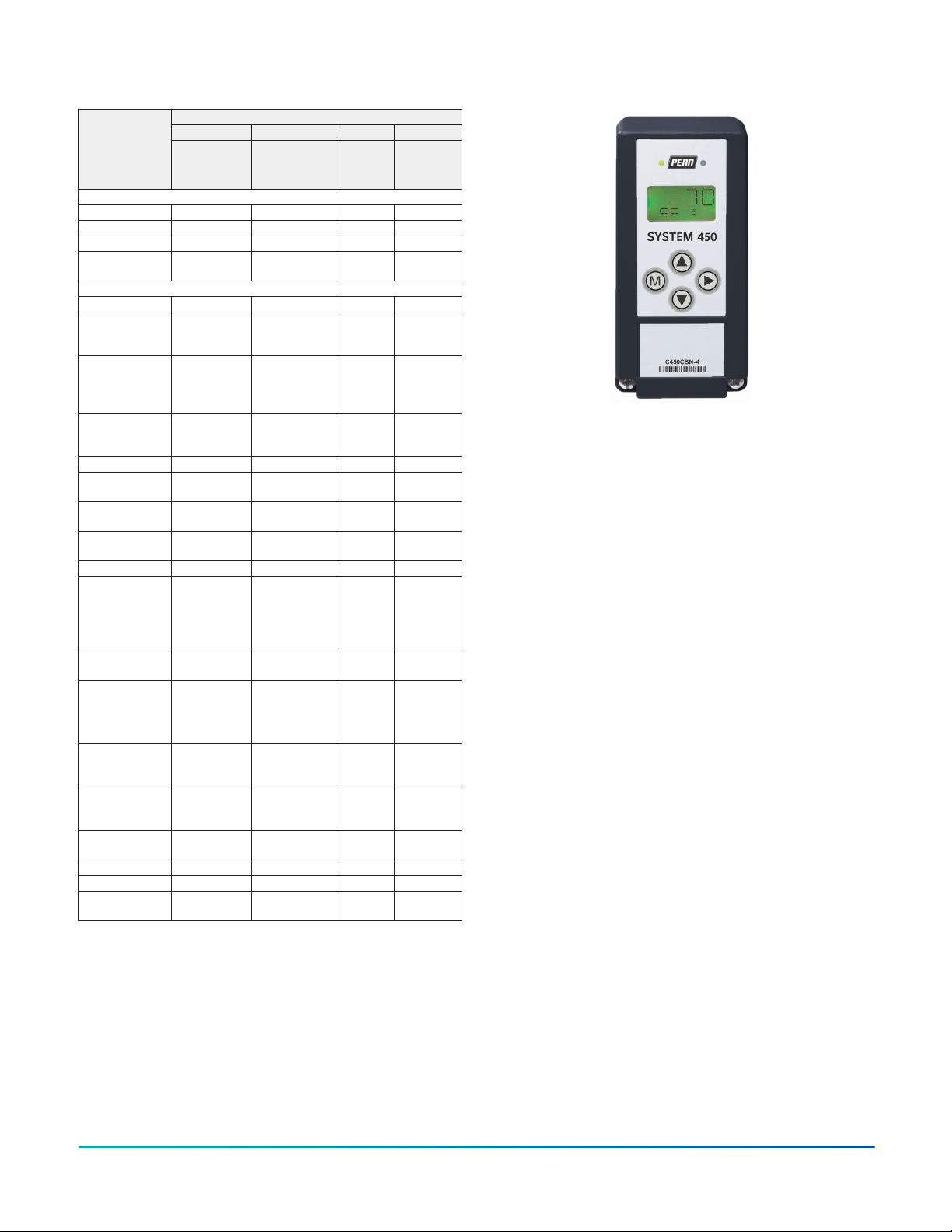
Table 1: System 450 Control Module capabilities
Control by ________
Controlled condition
Temperature X X X X
Pressure X X - X
Humidity X X X X
Combination of
conditions
Control capabilities
On/Off relay control X X X X
Analog proportional
control (direct and
reverse action)
Analog proportional
plus integral control
(direct and reverse
action)
Combination of On/
Off relay and analog
output control
Stand-alone control X - X X
Multi-stage control
(relay or analog)
Network
communications
High input signal
selection
Differential control X X - X
Output signal
limiting
output signal
update rate
Output signal
deadband
Binary input control
for relay outputs
On/Off duration
time control
Minimum On/Off
time
On/Off time delay
Temperature and
humidity reset
control
Scheduling and
temperature
setback control
Reset setpoint
control
Setback scheduling - - X -
Run-time balancing - - X -
Hybrid analog
output control
1 Only on output OUTA1.
System 450 Control Modules
Standard Communications Reset Hybrid
C450CPN-4
C450CQN-4
C450CBN-4
C450CCN-4
C450CEN-1
C450CRN-1
X X X X
X X X X
X X X X
X X X X
X X X X
- X - -
X X - X
X X - -
X X - -
X X - -
- - X -
- - X -
- - X -
- - -
C450RBN-3
C450RCN-3
C450CPW-400
1
1
X
System 450 control modules
The System 450 control module is the supervisor of your
control system and the interface for the system’s inputs,
supply power, and outputs.
Figure 5 shows an example System 450 control module.
See Table 1 and Table 2 for information on all of the
available control modules.
Figure 5: C450CBN Standard control module
All System 450 control systems require a control module
to set up the control system’s inputs and outputs, monitor
the control system’s status, and control the system’s
outputs.
System 450 control modules can monitor up to three
inputs and control up to 10 outputs in any combination of
relay and analog outputs provided by expansion modules.
User-friendly LCD and touchpad UI
The System 450 control modules feature a backlit LCD
screen that displays the real-time status of the sensors
that are set up in your control system during normal
operation. The four-button touchpad enables you to
quickly scroll through and view the output status screens
and access the system setup screens to set up or adjust
the sensors and outputs in your control system.
After you assemble and power your control system, and
select the Sensor Types in the UI, the control module
automatically determines the output numbers and output
types. The control module then generates the menubased setup screens and supplies all of the default setup
values required to set up your custom control system.
System 450 standard control modules
Configure the System 450 standard control modules out
of the box as stand-alone controls that can provide SPDT
control or proportional analog signal control, depending
on the model, for a wide range of HVAC, commercial, and
industrial process applications. The following standard
control modules are available:
• C450CBN-4 control module has one SPDT relay output
• C450CCN-4 control modules have two SPDT relay
outputs
• C450CPN-4 control modules have one analog output
(0VDC to 10 VDC or 4 mA to 20 mA)
• C450CQN-4 control modules have two analog outputs
(0 VDC to 10 VDC or 4 mA to 20 mA)
With a standard control module and the available sensors
and transducers, almost any temperature, pressure, or
humidity control you may encounter in the field can be
System 450 Series Modular Controls Product Bulletin 5
quickly replaced with a System 450 control system. See
Table 1 for capabilities of the standard control modules.
System 450 reset control modules
Reset control modules provide many of the features of the
standard control modules for temperature and humidity
control. In addition, these modules provide temperature
and humidity reset, real-time setback, and run-time
balancing capability. The following reset control modules
are available:
• C450RBN-3 (one SPDT relay output)
• C450RCN-3 (two SPDT relay outputs)
See Table 1 for capabilities of the System 450 reset control
modules.
Reset control modules control temperature and humidity,
but not pressure.
System 450 hybrid analog output control modules
A System 450 hybrid analog output control module
can provide the same control as the standard control
modules, while providing a hybrid analog output control
option for controlling EC motors.
The hybrid analog output control feature enables an
analog VDC output to transition to a pulse output at
low signal levels. This provides more efficient lowspeed control of EC variable speed motors. These EC
variable speed motors are typically used in condenser fan
applications on a wide variety of refrigeration and HVAC
condensing units.
The onboard analog output can also be configured
for High Input Signal Selection, which enables precise
and efficient EC motor speed control on multi-circuit
condensing units.
See Table 1 for capabilities of the System 450 Hybrid
Analog Output control modules.
including multipurpose control systems that control
temperature, pressure, and humidity simultaneously.
You do not need to purchase additional and unnecessary
features and components associated with packaged
control systems, which reduces your control system costs
to just the inputs, outputs, and features required by your
application.
System 450 components allow you to build control
systems that include:
• one to 10 outputs provided by the control module and
expansion modules, each output providing either on/
off control or a proportional analog signal (0 VDC to
10 VDC or 4 mA to 20 mA) to the equipment in your
controlled system
• one to three sensors or transducers, which are hardwired directly to the control module and provide input
signals for monitoring and controlling your system
equipment
• an optional power module to provide power to the
control module, expansion modules, and the input
sensors and transducers
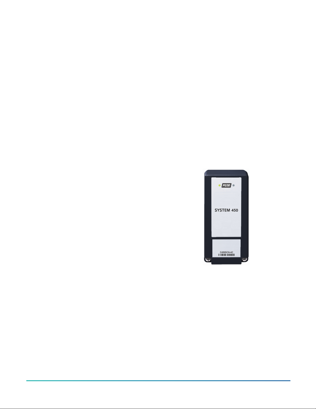
Expansion modules
Figure 6: C450SCN Relay Expansion Module
System 450 control modules with communications
A System 450 control module with communications
provides the same types of control as the standard control
modules. See Table 1 for capabilities of the System 450
control modules with communications.
C450CEN-1 control modules feature an RJ45 Ethernet
network port that enables you to connect your control
system to an Ethernet network and communicate across
it.
C450CRN-1 control modules feature an RS485 terminal
block that enables you to connect your control system to
an RS485 MODBUS network and communicate on it.
System 450 communications control modules do not
provide onboard outputs and require expansion modules
to provide outputs.
Other System 450 components
The System 450 suite of components enables you to
build a wide variety of cost-effective, custom control
systems that meet your specific application requirements;
System 450 Series Modular Controls Product Bulletin6
The System 450 expansion modules allow you to increase
the number of outputs in your control system to meet
your application requirements. The following models are
available:
• C450SBN-4 or C450SBG-4: Relay expansion module with
one relay output
• C450SCN-4 or C450SCG-4: Relay expansion module with
two relay outputs (Figure 6)
• C450SPN-4: Analog expansion module with one analog
output
• C450SQN-4: Analog expansion module with two analog
outputs
For further information, see Ordering Information and
Technical Specifications.

Power module
Figure 7: C450YNN power module
The System 450 modules require 24 VAC - Class 2 power.
The C450YNN-1 Power module (Figure 7) provides a
convenient means of transforming 120/240 VAC to 24 VAC
to power System 450 control systems.
System 450 compatible sensors and transducers
System 450 control modules are designed to operate with
a variety of compatible sensors and transducers. The
System 450 compatible sensors and transducers cover
a wide range of temperature, pressure, and humidity
conditions.
System 450 compatible sensors and transducers come in a
variety of styles and configurations, allowing you to select
the sensor or transducer that best fits your control system
requirements.
For ease of installation and setup, the Sensor Type
that you select in the UI for a sensor or transducer
automatically determines the sensed condition, unit of
measurement, minimum differential, setup value ranges,
and the default setup values for each control system
output that references the sensor or transducer.
See Table 4 for compatible A99 Series Temperature
Sensors (Figure 8). Refer to the A99B Series Temperature
Sensors Product/Technical Bulletin (LIT-125186) for further
information.
Figure 8: A99B Series temperature sensors
See Table 5 for compatible TE-6000 Series temperature
sensing elements (Figure 9). Refer to the TE-6000 Series
Temperature Sensing Elements Product Bulletin (LIT-216288)
for further information.
Figure 9: TE-6000-1 temperature sensing element
See Table 6 for compatible TE-6300 Series Temperature
Sensors (Figure 10). Refer to the TE-6300 Series
Temperature Sensors Product Bulletin (LIT-216320) for
further information.
Figure 10: TE-6300 Series temperature sensors
See Table 7 for compatible TE-6800 Series Wall Mount
Temperature Sensors (Figure 11). Refer to the TE-6800
Series Temperature Sensors Product Bulletin (LIT-12011542)
for more information.
System 450 Series Modular Controls Product Bulletin 7

Figure 11: TE-6800 Series wall mount temperature
sensor
See Table 9 for compatible HE-6800 Series Humidity
Transmitters with Temperature Sensors (Figure 12).
Refer to the HE-6800 Series Humidity Transmitters with
Temperature Sensor Product Bulletin (LIT-12011625) for more
information.
Figure 12: HE-6800 Series humidity transmitter with
temperature sensor
Figure 14: DPT265 Series low pressure differential
pressure transducers
See Table 11, Table 12, and Table 13 for compatible P599
Series pressure transducers (Figure 15). Refer to the P599
Series Electronic Pressure Transducers Product/Technical
Bulletin (LIT-12012446, Part No. 24-7664-3264) for more
information.
Figure 15: P599 Series pressure transducers
See Table 8 for compatible HE-69S0NP Type humidity
sensors with integral A99B temperature sensor (Figure
13). Refer to the HE-69xx Series Duct Probe Humidity and
Temperature Sensors Product Bulletin (LIT-12013478) for
more information.
Figure 13: HE-69SxONP humidity sensor
See Table 10 for compatible DPT265 Series low pressure
differential transducers (Figure 14). For further
information, see the Setra Systems Model DPT265 Very Low
Differential Pressure Transducer Catalog Page.
System 450 applications
You can create a wide variety of custom, applicationspecific control systems with System 450 modules.
The following are some common control application
examples, most of which can be enhanced by using one of
the System 450 control modules with Communication:
• Temperature control
• Pressure control
• Humidity control
• Multipurpose control
• Reset and setback control
• High input-signal selection
• Differential control
Temperature control
• Temperature monitoring and alarming
• On/Off staged control of boilers and chillers
• Proportional stage control of boilers and chillers
• Boiler and chiller pump control
• Heating and cooling control with deadband
• Floating temperature control of damper and valve
actuators
System 450 Series Modular Controls Product Bulletin8

• Cooling tower fan speed/stage control based on water
temperature
• Supply, make-up, and mixed air temperature control
• Temperature actuated valve control
• Supply and make-up air damper and fan control
• Condenser fan staging or speed control based on
condenser temperature
Refrigerant pressure control
• Condenser fan cycling and stage control
• Multispeed condenser fan control
• Floating pressure control of damper and valve
actuators
• Condenser fan speed and damper control
• High and low pressure cutout control
• Staged compressor control
• Cooling tower fan speed control based on high-side
pressure
• Direct speed control of EC condenser fan motors
(C450CPW-400 model)
Other pressure control
• Relief damper and fan control for building
pressurization
• Constant static pressure control
Humidity control
• On/Off humidification and dehumidification control
• Proportional humidification and dehumidification
control
• Multistage humidification and dehumidification control
• Humidity monitoring and alarming
Multipurpose control
• Temperature and pressure-based refrigeration rack
control
• Temperature and humidity control of wine cellars and
greenhouses
• Temperature, humidity, and static pressure control of
clean rooms and greenhouses
• Dehumidification with reheat control
Reset control
• Boiler supply water temperature reset control based on
outside air temperature
• Chiller supply water temperature reset control based
on outside air temperature
• VAV zone temperature control based on outside air
temperature
• Humidity reset based on outside air temperature
• Staged applications with run-time balancing
• Real-time Occupied/Unoccupied setback
Differential control
• Air and fluid pump-flow monitoring and alarming
• Air and fluid filter-status monitoring and alarming
• Chiller barrel flow monitoring, control, and alarming
• Solar air and water heating applications
System 450 control system examples
With System 450 control and expansion modules, you
can build a wide variety of cost-effective, custom control
systems. Each of the following examples is accompanied
by an illustration of the module assembly, including
wiring diagrams for system sensors and outputs.
For menu flow charts showing typical Main screens and
System Status screens, along with System Setup screens
and example setup values, refer to one of the following
technical bulletins:
• For control systems with standard control modules
and the control module with hybrid analog output,
refer to the System 450™ Series Modular Control
Systems with Standard Control Modules Technical Bulletin
(LIT-12011459).
• For control systems with reset control modules, refer
to the System 450™ Series Modular Control Systems with
Reset Control Modules Technical Bulletin (LIT-12011842).
• For control systems with communications control
modules, refer to the System 450™ Series Modular
Control Systems with Communications Control Modules
Technical Bulletin (LIT-12011826).
Note: The physical configurations, wiring, and setup
values shown in the following examples are meant
to illustrate typical control system applications and
control features. Your control applications may
require different modules, module configurations,
sensors, and wiring.
Multipurpose cooling application with Modbus communications
Figure 16 shows an example System 450 control system
with Modbus network communications that controls a
cooling system and provides condenser fan speed control.
Figure 16: Example system 450 Control with Modbus
communications showing a room cooling application
with condenser fan speed control
High input signal selection
• Pressure-based fan speed or fan cycling control on
multi-circuit condensers
• Temperature-based fan speed or fan cycling control on
multi-circuit condensers
System 450 Series Modular Controls Product Bulletin 9

Multipurpose application for a clean room
Figure 17 shows a standard System 450 control system
for a clean room application that controls temperature,
pressure, and humidity with both relay and analog
outputs.
System 450 solar water heating example with differential control
Figure 19 shows a Modbus System 450 control system
example of a solar water heating and storage application
that uses the differential control feature to control two
circulation pumps.
Figure 17: Example system 450 control showing a clean
room application that controls temperature, pressure,
and humidity simultaneously
Boiler water temperature reset example with three-staged boilers
Figure 18 shows a System 450 reset control system that
uses an outdoor air temperature master sensor and a
supply water temperature sensor configured to reset
the boiler supply water temperature relative to the
outdoor air temperature. This control system can also
be configured to use the run-time balancing feature to
equalize the time that each of the three boilers run.
Figure 18: Example System 450 reset control system
for a three-stage boiler with or without run-time
balancing
Figure 19: Example System 450 control system with
Ethernet communications showing a solar water
heating application that uses the differential control
feature
Ordering information
Table 2: System 450 modules and accessories ordering
information
Product code
number
C450CBN-4 Standard control module with LCD, four-button
C450CCN-4 Standard control module with LCD, four-button
C450CPN-4 Standard control module with LCD, four-button
C450CQN-4 Standard control module with LCD and four-
Product description
touchpad UI, and relay output; provides one relay
output (SPDT line-voltage relay) for SPDT control.
touchpad UI, and relay output; provides two
relay outputs (SPDT line-voltage relays) for SPDT
control.
touchpad UI, and analog output; provides
one analog output (0–10 VDC or 4–20 mA selfselecting signal) for proportional control.
button touchpad UI, and analog output; provides
two analog outputs (0–10 VDC or 4–20 mA selfselecting signals) for proportional control.
System 450 Series Modular Controls Product Bulletin10

Table 2: System 450 modules and accessories ordering
information
Product code
number
C450RBN-3 Reset control module with LCD, four-button
C450RCN-3 Reset control module with LCD, four-button
C450CEN-1 Control module with Ethernet communications,
C450CRN-1 Control module with RS485 Modbus
C450CPW-400 Hybrid analog output control module with LCD,
C450SBN-4 Relay output expansion module; provides one
C450SCN-4 Relay output expansion module; provides two
C450SBG-4 Relay output expansion module; provides one
C450SCG-4 Relay output expansion module; provides two
C450SPN-4 Analog output expansion module; provides
C450SQN-4 Analog output expansion module; provides
C450YNN-1 Power module; provides 24 V to System 450
Product description
touchpad UI, and SPDT relay output; provides one
SPDT output relay. One A99BC-25C temperature
sensor with 0.25 m (9-1/4 in.) silicon leads and
one A99BC-300C temperature sensor with 3 m (9
ft 10 in.) silicon leads are included in the box with
the Reset control Module.
touchpad UI, and SPDT relay output; provides two
SPDT output relays. One A99BC-25C temperature
sensor with 0.25 m (9-1/4 in.) silicon leads and
one A99BC-300C temperature sensor with 3 m (9
ft 10 in.) silicon leads are included in the box with
the reset control module.
LCD, and four-button touchpad UI. (No onboard
outputs available on control modules with
network communications capabilities.)
communications, LCD, and four-button touchpad
UI. (No onboard outputs available on control
modules with network communications
capabilities.)
four-button touchpad UI, hybrid analog output
and optional high input signal select; provides
one hybrid analog output and optional high input
signal select primarily used for variable-speed EC
motor speed control.
Only analog output 1 (OUTA1) can be configured
as a hybrid analog output and/or use the high
input signal selection feature. These features
are not available for any of the other outputs
in a System 450 control system that uses the
C450CPW-400C as the control module.
SPDT line-voltage relay output.
SPDT line-voltage relay outputs.
SPDT low voltage/current output.
SPDT low voltage/current relay outputs.
one analog output (0–10 VDC or 4–20 mA selfselecting signal) for proportional control.
two analog outputs (0–10 VDC or 4–20 mA selfselecting signals) for proportional control.
Module Assembly; 120 VAC or 240 VAC supply
power input terminals.
Table 3: System 450 mounting accessories
Product Code
Number
BKT287-1R DIN rail; 0.30 m (12 in.) long
BKT287-2R DIN rail; 1 m (39-1/3 in.) long
BKT287-3R DIN rail; 0.61 m (24 in.) long
BKT287-4R DIN rail; 0.36 m (14 in.) long
PLT344-1R DIN rail end clamps (2 clamps)
WHA-
C450-100C
Product Description
System 450 module connection extension cable,
100 cm (3.3 ft) long
Table 4: System 450 Compatible A99B Temperature
Sensors and accessories ordering information
1
Product code
number
A99BA-200C PTC silicon sensor with shielded cable; cable
A99BB-25C PTC silicon sensor with PVC cable; cable length
A99BB-200C PTC silicon sensor with PVC cable; cable length 2
A99BB-300C PTC silicon sensor with PVC cable; cable length 3
A99BB-500C PTC silicon sensor with PVC cable; cable length 5
A99BB-600C PTC silicon sensor with PVC cable; cable length 6
A99BC-25C PTC silicon sensor with high temperature silicon
Product description
1
length 2 m (6-1/2 ft);
Sensor temperature range: -40 to 120°C (-40 to
250°F)
Cable jacket temperature range: -40 to 100°C
(-40 to 212°F)
0.25 m (9-3/4 in.);
Sensor temperature range: -40 to 120°C (-40 to
250°F)
Cable jacket temperature range: -40 to 100°C
(-40 to 212°F)
m (6-1/2 ft);
Sensor temperature range: -40 to 120°C (-40 to
250°F)
Cable jacket temperature range: -40 to 100°C
(-40 to 212°F)
m (9-3/4 ft);
Sensor temperature range: -40 to 120°C (-40 to
250°F)
Cable jacket temperature range: -40 to 100°C
(-40 to 212°F)
m (16-3/8 ft);
Sensor temperature range: -40 to 120°C (-40 to
250°F)
Cable jacket temperature range: -40 to 100°C
(-40 to 212°F)
m (19-1/2 ft);
Sensor temperature range: -40 to 120°C (-40 to
250°F)
Cable jacket temperature range: -40 to 100°C
(-40 to 212°F)
cable; cable length 0.25 m (9-3/4 in.)
Sensor temperature range: -40 to 120°C (-40 to
250°F)
Cable jacket rated for full sensor temperature
range.
System 450 Series Modular Controls Product Bulletin 11

Table 4: System 450 Compatible A99B Temperature
Sensors and accessories ordering information
1
Product code
number
Product description
1
A99BC-300C PTC silicon sensor with high temperature silicon
cable; cable length 3 m (9-3/4 ft)
sensor temperature range: -40 to 120°C (-40 to
250°F)
Cable jacket rated for full sensor temperature
range.
A99BC-1500C PTC silicon sensor with high temperature silicon
cable; cable length 15 m (49 ft)
Sensor temperature range: -40 to 120°C (-40 to
250°F)
Cable jacket rated for full sensor temperature
range.
BOX10A-600R PVC enclosure for A99 sensor; includes wire nuts
and conduit connector for outdoor sensor
WEL11A-601R Immersion well for A99 sensor liquid sensing
applications
A99-CLP-1 Mounting clip for A99 temperature sensor
ADP11A-600R Conduit adaptor, 1/2 in. snap-fit EMT conduit
adaptor (box of 10)
TE-6001-1 Duct mounting hardware with handy box for
A99 sensor
TE-6001-11 Duct mounting hardware without handy box for
A99 sensor
SHL10A-603R Sun shield for use with outside A99 sensors in
sunny locations
1 Refer to the A99B Series Temperature Sensors Product/
Technical Bulletin (LIT-125186) for more information.
Table 5: System 450 Compatible TE-6000 Series 1,000
Ohm Nickel Temperature Sensors and accessories
ordering information
Product code
number
TE-6000-1
TE-6000-1x
TE-6000-6
Product description
TE6000 Series 1,000 ohms at 21°C (70°F) nickel
temperature sensors (only). Only the TE-6000-6
sensor can be used for the entire HI°C and
HI°F temperature range. Different sensing
element packages are available for various
applications. For a complete list of compatible
1,000 ohm nickel sensors, including sensor
descriptions, technical specifications, and
mounting accessories, refer to theTE-6000 Series
Temperature Sensing Elements Product Bulletin
(LIT-216288). (System 450 Sensor Types HI°C and
HI°F)
Table 6: System 450 Compatible TE-6300 Series 1,000
Ohm Nickel Temperature Sensors and accessories
ordering information
Product code
number
TE-631xx-x TE6300 Series 1,000 ohm at 21°C (70°F) nickel
Product description
averaging and 1,000 ohm thin-film nickel
temperature sensors only. For a complete
list of compatible 1,000 ohm nickel averaging
and thin-film nickel sensors, including sensor
descriptions, technical specifications, and
mounting accessories, refer to the TE-6300 Series
Temperature Sensors Product Bulletin (LIT-216320).
(System 450 Sensor Types HI°C and HI°F.)
Table 7: System 450 Compatible TE-68NT-0N00S 1,000
Ohm Nickel Temperature Sensor ordering information
Product code
number
TE-68NT-0N00S TE6800 Series 1,000 ohm at 21°C (70°F)
Product description
nickel temperature sensor for wall-mount
applications. For more information, including
sensor description, technical specifications,
and mounting accessories, refer to the TE-6800
Series Temperature Sensors Product Bulletin
(LIT-12011542).
Note: For correct readings, set the
temperature sensor to HI°C or HI°F.
Table 8: System 450 Compatible HE-69Sx0NP
Type Humidity Sensors with 100 ohm NTC nickel
temperature sensor ordering information
1
Product code
number
1
HE-69Sx0NP Duct mount humidity sensor with 1,000 ohm
1 The HE-69Sx0NP sensors require 24 VAC input and must
use the 0–5 VDC output. Refer to the HE-69xx Series Duct
Probe Humidity and Temperature Sensors Product Bulletin
(LIT-12013478) for more information, including technical
specifications and mounting accessories.
Product description
NTC nickel temperature sensor: 10% to 90% RH;
0 to 60°C (32 to 140°F)
System 450 Series Modular Controls Product Bulletin12

Table 9: System 450 Compatible HE6800 Series
Humidity Transmitters with Temperature Sensor
ordering information
1
Product code number
HE-68N2-0N00WS Wall mount humidity transmitter
HE-68N3-0N00WS Wall mount humidity transmitter
1 The HE-6800 transmitters require 24 VAC input and must
use the 0–5 VDC output. Refer to the HE-6800 Series Humidity
Transmitters with Temperature Sensor Product Bulletin
(LIT-12011625) for more information, including technical
specifications and mounting accessories.
1
Product description
with nickel temperature sensor:
10 to 90 ±2% RH; 0 to 55°C (32 to
131°F)
with nickel temperature sensor:
10 to 90 ±3% RH; 0 to 55°C (32 to
131°F)
Table 10: System 450 Compatible Low Pressure
Differential Transducer ordering information
1, 2
Product code number
DPT2650-R25B-AB Low pressure differential
DPT2650-0R5D-AB Low pressure differential
DPT2650-2R5D-AB Low pressure differential
DPT2650-005D-AB Low pressure differential
DPT2650-10D-AB Low pressure differential
1 Refer to the Setra Systems Model DPT265 Very Low Differential
Pressure Transducer Catalog Page for more information.
2 The DPT265 sensors require 24 VAC input and must use the
0–5 VDC output. Refer to the Setra Systems Model DPT265 Very
Low Differential Pressure Transducer Catalog Page for more
information.
3 Used only with communications control modules.
1,2
Product description
transducer: -0.25 to 0.25 in. W.C.
3
(System 450 Sensor Type:
ixia_locid="207">P 0.25)
transducer: 0 to 0.5 in. W.C.
(System 450 Sensor Type:
ixia_locid="213">P 0.5)
transducer: 0 to 2.5 in. W.C.
(System 450 Sensor Type:
ixia_locid="218">P 2.5)
transducer: 0 to 5.0 in. W.C.
(System 450 Sensor Type:
ixia_locid="223">P 5)
transducer: 0 to 10 in. W.C.
(System 450 Sensor Type:
ixia_locid="228">P 10)
3
Table 11: System 450 Compatible P599 Series
Transducers with 1/4 in. SAE 45 Flare Internal Thread
with Depressor (Style 47) ordering information
1
Product code
number
1
Product description
P599RCPS100C -10 to 100 psis, sealed for wet and freeze/
thaw applications; order WHA-PKD3 type wire
harness separately
P599RCPS100K -10 to 100 psis, sealed for wet and freeze/thaw
applications; WHA-PKD3-200C wire harness
included
P599RCPS102C 0 to 200 psis, sealed for wet and freeze/thaw
applications; order WHA-PKD3 type wire
harness separately
P599RCPS102K 0 to 200 psis, sealed for wet and freeze/thaw
applications; WHA-PKD3-200C wire harness
included
P599RCPS101C 0 to 100 psig; order WHA-PKD3 type wire
harness separately
P599RCPS101K 0 to 100 psig; WHA-PKD3-200C wire harness
included
P599RCPS105C 0 to 500 psig; order WHA-PKD3 type wire
harness separately
P599RCPS105K 0 to 500 psig; WHA-PKD3-200C wire harness
included
P599RCPS107C 0 to 750 psig; order WHA-PKD3 type wire
harness separately
P599RCPS107K 0 to 750 psig; WHA-PKD3-200C wire harness
included
1 The P599 sensors must be powered with the +5 VDC and C
terminals and the output is 0.5 to 4.5 VDC. Refer to the P599
Series Electronic Pressure Transducers Product/Technical Bulletin
(LIT-12012446, Part No. 24-7664-3264) for more information.
Table 12: System 450 Compatible P599 Series
Transducers with 1/8 in. 27 NPT External Thread (Style
49) ordering information
1
Product code
number
1
P599RAPS100C -10 to 100 psis, sealed for wet and freeze/
P599RAPS100K -10 to 100 psis, sealed for wet and freeze/thaw
P599RAPS102C 0 to 200 psis, sealed for wet and freeze/thaw
P599RAPS102K 0 to 200 psis, sealed for wet and freeze/thaw
P599RAPS101C 0 to 100 psig; order WHA-PKD3 type wire
P599RAPS101K 0 to 100 psig; WHA-PKD3-200C wire harness
Product description
thaw applications; order WHA-PKD3 type wire
harness separately
applications; WHA-PKD3-200C wire harness
included
applications; order WHA-PKD3 type wire
harness separately
applications; WHA-PKD3-200C wire harness
included
harness separately
included
System 450 Series Modular Controls Product Bulletin 13

Table 12: System 450 Compatible P599 Series
Transducers with 1/8 in. 27 NPT External Thread (Style
49) ordering information
1
Product code
number
1
Product description
P599RAPS102C 0 to 200 psig; order WHA-PKD3 type wire
harness separately
P599RAPS105C 0 to 500 psig; order WHA-PKD3 type wire
harness separately
P599RAPS105K 0 to 500 psig; WHA-PKD3-200C wire harness
included
P599RAPS107C 0 to 750 psig; order WHA-PKD3 type wire
harness separately
P599RAPS107K 0 to 750 psig; WHA-PKD3-200C wire harness
included
1 The P599 sensors must be powered with the +5 VDC and C
terminals and the output is 0.5 to 4.5 VDC. Refer to the P599
Series Electronic Pressure Transducers Product/Technical Bulletin
(LIT-12012446, Part No. 24-7664-3264) for more information.
Table 13: WHA-PKD3 Wire Harnesses ordering
information
1
Product code
number
1
WHA-PKD3-200C Plug and 3-Wire Harness for P599 Electronic
WHA-PKD3-400C Plug and 3-Wire Harness for P599 Electronic
WHA-PKD3-600C Plug and 3-Wire Harness for P599 Electronic
1 Refer to the P599 Series Electronic Pressure Transducers
Product/Technical Bulletin (LIT-12012446, Part No.
24-7664-3264) for more information.
Product description
Pressure Transducers: 2.0 m (6-1/2 ft) cable
Pressure Transducers: 4.0 m (13 ft) cable
Pressure Transducers: 6.0 m (19-5/8 ft) cable
System 450 Series Modular Controls technical specifications
Table 14: C450CPN-4 and C450CQN-4 Control Modules
with Analog Output technical specifications
Specification Description
Product C450CPN-4 and C450CQN-4: System 450
Control Module models are sensing controls
and operating controls with LCD, four-button
touchpad, and SPDT analog output
C450CPN-4: Control Module with one analog
output
C450CQN-4: Control Module with two analog
outputs
Power
consumption
Supply power Internal supply power: C450YNN-1 Power
Ambient
operating
conditions
Ambient shipping
and storage
conditions
Input signal 0 VDC to 5 VDC for humidity sensors and
Analog output
C450CPN-4: 1.3 VA maximum using 0 V to 10 V
out; 1.5 VA maximum using 4 mA to 20 mA out
C450CQN-4: 2.0 VA maximum using 0 to 10 V
out; 2.4 VA maximum using 4 mA to 20 mA out
Supply Module
External supply power: 24 VAC (20 VAC –
30 VAC) Safety Extra-Low Voltage (SELV)
(Europe), Class 2 (North America), 50/60 Hz,
10 VA minimum
Note: A System 450 control module or
module assembly can use an internal
or an external supply power source,
but must not be connected to both
simultaneously.
Temperature: -40 to 66°C (-40 to 150°F) when
using 0 VDC to 10 VDC outputs;-40 to 40°C (-40
to 104°F) when using 4 mA to 20 mA outputs
Humidity: Up to 95% RH noncondensing;
maximum dew point 29°C (85°F)
Temperature: -40 to 80°C (-40 to 176°F)
Humidity: Up to 95% RH noncondensing;
maximum dew point 29°C (85°F)
static pressure transducers
0.5 VDC to 4.5 VDC for ratiometric pressure
transducers
1,035 ohms at 25°C (77°F) for A99 PTC
temperature sensors
1,000 ohms at 21.1°C (70°F) for TE-6xxx Nickel
temperature sensors
Voltage Mode (0–10 VDC):
10 VDC maximum output voltage
10 mA maximum output current
Requires an external load of 1,000 ohms or
more
The AO operates in Voltage Mode when
connected to devices with impedance greater
than 1,000 ohms. Devices that fall below
1,000 ohms may not operate as intended with
Voltage Mode applications.
Current mode (4 mA to 20 mA):
Requires an external load between 0–300
ohms
The AO operates in Current Mode when
connected to devices with impedance less
than 300 ohms. Devices that rise above 300
ohms may not operate as intended with
Current Mode applications.
System 450 Series Modular Controls Product Bulletin14

Table 14: C450CPN-4 and C450CQN-4 Control Modules
with Analog Output technical specifications
Specification Description
Analog input
accuracy
Control
construction
Dimensions
(H x W x D)
Weight C450CPN-4: 195 g (0.43 lb)
Compliance United States: cULus Listed; UL 60730-1, File
Resolution: 14 bits
Independently mounted control, surface
mounted with Lexan® 950 enclosure suitable
for DIN rail mounting or direct mounting to a
hard, even surface.
127 x 61 x 61 mm (5 x 2-3/8 x 2-3/8 in.)
C450CQN-4: 195 g (0.43 lb)
E27734; FCC Compliant to CFR47, Part 15,
Subpart B, Class B
Canada: cULus Listed; CAN/CSA-E60730-1, File
E27734; Industry Canada (IC) Compliant to
Canadian ICES-003, Class B limits
Europe: CE Mark – Johnson Controls declares
that this product is in compliance with the
essential requirements and other relevant
provisions of the EMC Directive.
Australia and New Zealand: RCM mark,
Australia/NZ Emissions Compliant
Table 15: C450CEN-1 Control Module with Ethernet
Communications technical specifications
Specification Description
Product C450CEN-1: System 450 control modules are
sensing controls and operating controls with
LCD and four-button touchpad UI, Ethernet
communications capability, and no outputs.
C450CEN-1: Control module with Ethernet
communications capability
Supply power Internal Supply Power: C450YNN-1 Power
Supply Module
External Supply Power: 24 VAC (20 VAC to
30 VAC) Safety Extra-Low Voltage (SELV)
(Europe), Class 2 (North America), 50/60 Hz,
10 VA minimum
Note: A System 450 control module or
module assembly can use an internal
or an external supply power source,
but must not be connected to both
simultaneously.
Ambient
operating
conditions
Ambient shipping
and storage
conditions
Input signal 0–5 VDC; 1,035 ohms at 25°C (77°F) for an A99
Analog input
accuracy
Temperature: -40 to 66°C (-40 to 150°F)
Humidity: Up to 95% RH noncondensing;
maximum dew point 29°C (85°F)
Temperature: -40 to 80°C (-40 to 176°F)
Humidity: Up to 95% RH noncondensing;
maximum dew point 29°C (85°F)
PTC Temperature Sensor
Resolution: 16 bits
Table 15: C450CEN-1 Control Module with Ethernet
Communications technical specifications
Specification Description
Control
construction
Dimensions (H x
W x D)
Weight C450CEN-1: 207 g (0.46 lb)
Compliance United States: cULus Listed; UL 60730-1, File
Independently mounted control, surface
mounted with Lexan® 950 enclosure suitable
for DIN rail mounting or direct mounting to a
hard, even surface.
127 x 63 x 63 mm (5 x 2-3/8 x 2-3/8 in.)
E27734; FCC Compliant to CFR47, Part 15,
Subpart B, Class B
Canada: cULus Listed; CAN/CSA-E60730-1, File
E27734; Industry Canada (IC) Compliant to
Canadian ICES-003, Class B limits
Europe: CE Mark – Johnson Controls declares
that this product is in compliance with the
essential requirements and other relevant
provisions of the EMC Directive.
Australia and New Zealand: RCM mark,
Australia/NZ Emissions Compliant
Table 16: C450CRN-1 Control Module with RS485
MODBUS Communications technical specifications
Specification Description
Product C450CRN-1: System 450 control modules are
sensing controls and operating controls with
LCD and four-button touchpad UI and no
outputs. This control module is an RS485, RTU
compliant MODBUS subordinate device.
Supply power Internal supply power: C450YNN-1 Power
Supply Module
External supply power: 24 VAC (20–30 VAC)
Safety Extra-Low Voltage (SELV) (Europe),
Class 2 (North America), 50/60 Hz, 10 VA
minimum
Note: A System 450 control module or
module assembly can use an internal
or an external supply power source,
but must not be connected to both
simultaneously.
Ambient
operating
conditions
Ambient shipping
and storage
conditions
Input signal 0–5 VDC; 1,035 ohms at 25°C (77°F) for an A99
Analog input
accuracy
Control
construction
Dimensions
(H x W x D)
Temperature: -40 to 66°C (-40 to 150°F)
Humidity: Up to 95% RH noncondensing;
maximum dew point 29°C (85°F)
Temperature: -40 to 80°C (-40 to 176°F)
Humidity: Up to 95% RH noncondensing;
maximum dew point 29°C (85°F)
PTC Temperature Sensor
Resolution: 16 bits
Independently mounted control, surface
mounted with Lexan® 950 enclosure suitable
for DIN rail mounting or direct mounting to a
hard, even surface.
127 x 63 x 63 mm (5 x 2-3/8 x 2-3/8 in.)
System 450 Series Modular Controls Product Bulletin 15

Table 16: C450CRN-1 Control Module with RS485
MODBUS Communications technical specifications
Specification Description
Weight C450CRN-1: 207 g (0.46 lb)
Compliance United States: cULus Listed; UL 60730-1, File
E27734; FCC Compliant to CFR47, Part 15,
Subpart B, Class B
Canada: cULus Listed; CAN/CSA-E60730-1, File
E27734; Industry Canada (IC) Compliant to
Canadian ICES-003, Class B limits
Europe: CE Mark – Johnson Controls declares
that this product is in compliance with the
essential requirements and other relevant
provisions of the EMC Directive; CISPR22, class
B
Australia and New Zealand: RCM mark,
Australia/NZ Emissions Compliant
Table 17: C450CPW-400 Control Module with Hybrid
Analog Output technical specifications
Specification Description
Product C450CPW-400 System 450 control module
is a sensing control and operating control
with LCD, four-button touchpad, and
analog output with pulse-width modulation
capability.
Power
consumption
Supply power Internal supply power: C450YNN-1 Power
Ambient
operating
conditions
Ambient shipping
and storage
conditions
Input signal 0–5 VDC for humidity sensors and static
C450CPW-400: 1.3 VA maximum using 0>–10 V
out; 1.5 VA maximum using 4 mA –20 mA out
Supply Module
External supply power: 24 VAC (20>–30 VAC)
Safety Extra-Low Voltage (SELV) (Europe),
Class 2 (North America), 50/60 Hz, 10 VA
minimum
Note: A System 450 control module or
module assembly can use an internal
or an external supply power source,
but must not be connected to both
simultaneously.
Temperature: -40 to 66°C (-40 to 150°F) when
using 0–10 VDC outputs; -40 to 40°C (-40 to
104°F) when using 4–20 mA outputs
Humidity: Up to 95% RH noncondensing;
maximum dew point 29°C (85°F)
Temperature: -40 to 80°C (-40 to 176°F)
Humidity: Up to 95% RH noncondensing;
maximum dew point 29°C (85°F)
pressure transducers
0.5–4.5 VDC for ratiometric pressure
transducers
1,035 ohms at 25°C (77°F) for A99 PTC
temperature sensors
1,000 ohms at 21.1°C (70°F) for TE-6xxx Nickel
temperature sensors
Table 17: C450CPW-400 Control Module with Hybrid
Analog Output technical specifications
Specification Description
Analog output
Analog input
accuracy
Control
construction
Dimensions
(H x W x D)
Weight C450CPW-400: 195 g (0.43 lb)
Compliance United States: cULus Listed; UL 60730-1, File
Voltage mode (0–10 VDC):
10 VDC maximum output voltage
10 mA maximum output current
Requires an external load of 1,000 ohms or
more
The AO operates in Voltage Mode when
connected to devices with impedance greater
than 1,000 ohms. Devices that fall below
1,000 ohms may not operate as intended with
Voltage Mode applications.
Current mode (4–20 mA):
Requires an external load between 0–300
ohms
The AO operates in Current Mode when
connected to devices with impedance less
than 300 ohms. Devices that rise above 300
ohms may not operate as intended with
Current Mode applications.
Resolution: 14 bits
Independently mounted control, surface
mounted with LEXAN 950 enclosure suitable
for DIN rail mounting or direct mounting to a
hard, even surface.
127 x 61 x 61 mm (5 x 2-3/8 x 2-3/8 in.)
E27734; FCC Compliant to CFR47, Part 15,
Subpart B, Class B
Canada: cULus Listed; CAN/CSA-E60730-1, File
E27734; Industry Canada (IC) Compliant to
Canadian ICES-003, Class B limits
Europe: CE Mark – Johnson Controls declares
that this product is in compliance with the
essential requirements and other relevant
provisions of the EMC Directive.
Australia and New Zealand: RCM mark,
Australia/NZ Emissions Compliant
System 450 Series Modular Controls Product Bulletin16

Table 18: C450CBN-4 and C450CCN-4 Control Modules
with Relay Output technical specifications
Specification Description
Product C450CBN-4 and C450CCN-4: System 450
Control Module models are sensing controls
and operating controls with LCD, four-button
touchpad, and SPDT relay output
C450CBN-4: Control Module with one SPDT
output relay
C450CCN-4: Control Module with two SPDT
output relays
Power
consumption
Supply power Internal supply power: C450YNN-1 Power
Ambient
operating
Conditions
Ambient shipping
and storage
conditions
Input signal 0–5 VDC for humidity sensors and static
contacts
Analog input
accuracy
Control
construction
Dimensions
(H x W x D)
Weight C450CBN-4: 209 g (0.46 lb)
C450CBN-4: 0.9 VA maximum
C450CCN-4: 1.3 VA maximum
Supply Module
External supply power: 24 VAC (20–30 VAC)
Safety Extra-Low Voltage (SELV) (Europe),
Class 2 (North America), 50/60 Hz, 10 VA
minimum
Note: A System 450 control module or
module assembly can use an internal
or an external supply power source,
but must not be connected to both
simultaneously.
Temperature: -40 to 66°C (-40 to 150°F)
Humidity: Up to 95% RH noncondensing;
maximum dew point 29°C (85°F)
Temperature: -40 to 80°C (-40 to 176°F)
Humidity: Up to 95% RH noncondensing;
maximum dew point 29°C (85°F)
pressure transducers
0.5–4.5 VDC for ratiometric pressure
transducers
1,035 ohms at 25°C (77°F) for A99 PTC
temperature sensors
1,000 ohms at 21.1°C (70°F) for TE-6xxx Nickel
temperature sensors
General: 1/2 HP at 120/240 VAC, SPDTOutput relay
Specific:
AC Motor Ratings:
120 VAC
• AC Full-load amperes: 9.8 A
• Locked-rotor amperes: 58.8 A
208/240 VAC
• AC full-load amperes: 4.9 A
• Locked-rotor amperes: 29.4 A
10 amperes AC non-inductive at 24/240 VAC
Pilot duty: 125 VA at 24/240 VAC
Resolution: 14 bits
Independently mounted control, surface
mounted with LEXAN 950 enclosure suitable
for DIN rail mounting or direct mounting to a
hard, even surface.
127 x 61 x 61 mm (5 x 2-3/8 x 2-3/8 in.)
C450CCN-4: 222 g (0.49 lb)
Table 18: C450CBN-4 and C450CCN-4 Control Modules
with Relay Output technical specifications
Specification Description
Compliance United States: cULus Listed; UL 60730-1, File
E27734; FCC Compliant to CFR47, Part 15,
Subpart B, Class B
Canada: cULus Listed; CAN/CSA-E60730-1, File
E27734; Industry Canada (IC) Compliant to
Canadian ICES-003, Class B limits
Europe: CE Mark – Johnson Controls declares
that this product is in compliance with the
essential requirements and other relevant
provisions of the EMC Directive.
Australia and New Zealand: RCM mark,
Australia/NZ Emissions Compliant
Table 19: C450RBN-3 and C450RCN-3 Reset Control
Modules with Real-Time Clock and Relay Output
technical specifications
Specification Description
Product C450RBN-3 and C450RCN-3: System 450 Reset
Control Module models are sensing controls
and operating controls with LCD, four-button
touchpad, and SPDT relay output
C450RBN-3: Control Module with one SPDT
output relay
C450RCN-3: Control Module with two SPDT
output relays
Power
consumption
Supply power Internal supply power: C450YNN-1 Power
Ambient
operating
conditions
Ambient shipping
and storage
conditions
Input signal 0–5 VDC for humidity sensors
C450RBN-3: 0.9 VA maximum
C450RCN-3: 1.3 VA maximum
Supply Module
External supply power: 24 VAC (20–30 VAC)
Safety Extra-Low Voltage (SELV) (Europe),
Class 2 (North America), 50/60 Hz, 10 VA
minimum
Note: A System 450 control module or
module assembly can use an internal
or an external supply power source,
but must not be connected to both
simultaneously.
Temperature: -40 to 66°C (-40 to 150°F)
Humidity: Up to 95% RH noncondensing;
maximum dew point 29°C (85°F)
Temperature: -40 to 80°C (-40 to 176°F)
Humidity: Up to 95% RH noncondensing;
maximum dew point 29°C (85°F)
1,035 ohms at 25°C (77°F) for A99 PTC
temperature sensors
System 450 Series Modular Controls Product Bulletin 17

Table 19: C450RBN-3 and C450RCN-3 Reset Control
Modules with Real-Time Clock and Relay Output
technical specifications
Specification Description
General: 1/2 HP at 120/240 VAC, SPDTOutput relay
contacts
Clock accuracy ±4 minutes per year
Clock backup
power
Setback events One occupied and one unoccupied event per
Analog input
accuracy
Control
construction
Dimensions
(H x W x D)
Weight C450RBN-3: 209 g (0.46 lb)
Compliance United States: cULus Listed; UL 60730-1, File
Specific:
AC Motor ratings
120 VAC
• AC full-load amperes: 9.8 A
• AC locked-rotor amperes: 58.8 A
208/240 VAC
• AC full-load amperes: 4.9 A
• AC locked-rotor amperes: 29.4 A
10 amperes AC non-inductive at 24/240 VAC
Pilot duty: 125 VA at 24/240 VAC
12 hours, capacitor reserve
day; 7 day schedule
Resolution: 14 bits
Independently mounted control, surface
mounted with LEXAN 950 enclosure suitable
for DIN rail mounting or direct mounting to a
hard, even surface.
127 x 61 x 61 mm (5 x 2-3/8 x 2-3/8 in.)
C450RCN-3: 222 g (0.49 lb)
E27734; FCC Compliant to CFR47, Part 15,
Subpart B, Class B
Canada: cULus Listed; CAN/CSA-E60730-1, File
E27734; Industry Canada (IC) Compliant to
Canadian ICES-003, Class B limits
Europe: CE Mark – Johnson Controls declares
that this product is in compliance with the
essential requirements and other relevant
provisions of the EMC Directive.
Australia and New Zealand: RCM mark,
Australia/NZ Emissions Compliant
Table 20: C450SPN-4 and C450SQN-4 Expansion
Modules with Analog Output technical specifications
Specification Description
Product C450SPN-4: System 450 Expansion Module
with one Analog output
C450SQN-4: System 450 Expansion Module
with two Analog outputs
Power
consumption
Supply power Internal supply power: C450YNN-1 Power
Ambient
operating
conditions
Ambient shipping
and storage
conditions
Analog output
Control
construction
Dimensions
(H x W x D)
Weight C450SPN-4: 150 g (0.33 lb)
C450SPN-4: 1.1 VA max using 0–10 V out; 1.3
VA maximum using 4–20 mA out
C450SQN-4: 1.8 VA max using 0–10 V out; 2.2
VA maximum using 4–20 mA out
Supply Module
External supply power: 24 VAC (20–30 VAC)
Safety Extra-Low Voltage (SELV) (Europe),
Class 2 (North America), 50/60 Hz, 10 VA
minimum
Note: A System 450 control module or
module assembly can use an internal
or an external supply power source,
but must not be connected to both
simultaneously.
Temperature: -40 to 66°C (-40 to 150°F) when
using 0 to 10 VDC outputs; -40 to 40°C (-40 to
104°F) when using 4 to 20 mA outputs
Humidity: Up to 95% RH noncondensing;
maximum dew point 29°C (85°F)
Temperature: -40 to 80°C (-40 to 176°F)
Humidity: Up to 95% RH noncondensing;
maximum dew point 29°C (85°F)
Voltage mode (0 to 10 VDC):
10 VDC maximum output voltage
10 mA maximum output current
Requires an external load of 1,000 ohms or
more
Note: The AO operates in Voltage
Mode when connected to devices with
impedance greater than 1,000 ohms.
Devices that drop below 1,000 ohms
may not operate as intended with
Voltage Mode applications.
Current mode (4 to 20 mA):
Requires an external load between 0 to 300
ohms
Note: The AO operates in Current
Mode when connected to devices
with impedances less than 300 ohms.
Devices that exceed 300 ohms may not
operate as intended with Current Mode
applications.
Independently mounted control, surface
mounted with Lexan® 950 enclosure suitable
for DIN rail mounting or direct mounting to a
hard, even surface.
127 x 61 x 61 mm (5 x 2-3/8 x 2-3/8 in.)
C450SQN-4: 150 g (0.33 lb)
System 450 Series Modular Controls Product Bulletin18

Table 20: C450SPN-4 and C450SQN-4 Expansion
Modules with Analog Output technical specifications
Specification Description
Compliance United States: cULus Listed; UL 60730-1, File
E27734; FCC Compliant to CFR47, Part 15,
Subpart B, Class B
Canada: cULus Listed; CAN/CSA-E60730-1, File
E27734; Industry Canada (IC) Compliant to
Canadian ICES-003, Class B limits
Europe: CE Mark - Johnson Controls declares
that this product is in compliance with the
essential requirements and other relevant
provisions the EMC Directive.
Australia and New Zealand: RCM mark,
Australia/NZ Emissions Compliant
Table 21: C450Sxx-4 Expansion Modules with Relay
Output technical specifications
Specification Description
Product C450SBN-4: System 450 Expansion Module
with one SPDT output relay
C450SCN-4: System 450 Expansion Module
with two SPDT output relays
C450SBG-4: System 450 Expansion Module
with one SPDT low current/voltage output
relay
C450SCG-4: System 450 Expansion Module
with two SPDT low current/voltage output
relays
Power
consumption
Supply power Internal supply power: C450YNN-1 Power
Ambient
operating
conditions
Ambient shipping
and storage
conditions
C450SBx-4: 0.8 VA maximum
C450SCx-4: 1.2 VA maximum
Supply Module
External supply power: 24 VAC (20–30 VAC)
Safety Extra-Low Voltage (SELV) (Europe),
Class 2 (North America), 50/60 Hz, 10 VA
minimum
Note: A System 450 control module or
module assembly can use an internal
or an external supply power source,
but must not be connected to both
simultaneously.
Temperature: -40 to 66°C (-40 to 150°F)
Humidity: Up to 95% RH noncondensing;
maximum dew point 29°C (85°F)
Temperature: -40 to 80°C (-40 to 176°F)
Humidity: Up to 95% RH noncondensing;
maximum dew point 29°C (85°F)
Table 21: C450Sxx-4 Expansion Modules with Relay
Output technical specifications
Specification Description
Output relay
contacts
Control
construction
Dimensions
(H x W x D)
Weight C450SBx-4: 172 g (0.38 lb)
Compliance United States: cULus Listed; UL 60730-1, File
C450SxN-4
General: 1/2 HP at 120/240 VAC, SPDT
Specific:
AC motor ratings:
120 VAC
• AC full-load amperes: 9.8 A
• Locked-rotor amperes: 58.8 A
208/240 VAC
• AC full-load amperes: 4.9 A
• Locked-rotor amperes: 29.4 A
10 amperes AC non-inductive at 24/240 VAC
Pilot duty: 125 VA at 24/240 VAC
C450SxG-4
General: 2 amperes resistive at 48 VDC
Pilot duty: 360VA at 120VAC
Recommended dry circuit rating:
400 mW maximum at 28 VAC/VDC
Independently mounted control, surface
mounted with Lexan® 950 enclosure suitable
for DIN rail mounting or direct mounting to a
hard, even surface.
127 x 61 x 61 mm (5 x 2-3/8 x 2-3/8 in.)
C450SCx-4: 186 g (0.41 lb)
E27734; FCC Compliant to CFR47, Part 15,
Subpart B, Class B
Canada: cULus Listed; CAN/CSA-E60730-1, File
E27734; Industry Canada (IC) Compliant to
Canadian ICES-003, Class B limits
Europe: CE Mark - Johnson Controls declares
that this product is in compliance with the
essential requirements and other relevant
provisions the EMC Directive.
Australia and New Zealand: RCM mark,
Australia/NZ Emissions Compliant
Table 22: C450YNN-1 Power Supply Module technical
specifications
Specification Description
Product C450YNN-1: System 450 Power Supply
Module; 120 or 240 VAC stepdown to 24 VAC
Class 2 (North America) or SELV (Europe),
50/60 Hz, 10 VA minimum
Supply power 110/120 VAC or 220/240 VAC at 50/60 Hz (100
mA maximum)
Secondary power 24 VAC, 10 VA
Ambient
operating
Conditions
Ambient shipping
and storage
conditions
Temperature: -40 to 66°C (-40 to 150°F)
Humidity: Up to 95% RH noncondensing;
maximum dew point 29°C (85°F)
Temperature: -40 to 80°C (-40 to 176°F)
Humidity: Up to 95% RH noncondensing;
maximum dew point 29°C (85°F)
System 450 Series Modular Controls Product Bulletin 19

Table 22: C450YNN-1 Power Supply Module technical
specifications
Specification Description
Control
construction
Dimensions
(H x W x D)
Weight C450YNN-1: 390 gm (0.86 lb)
Compliance United States: cULus Listed; UL 60730-1, File
The performance specifications are nominal and conform to
acceptable industry standards. For application at conditions
beyond these specifications, consult Johnson Controls
Application Engineering at (414) 524–5535. Johnson Controls
shall not be liable for damages resulting from misapplication
or misuse of its products.
Independently mounted control, surface
mounted with LEXAN 950 enclosure suitable
for DIN rail mounting or direct mounting to a
hard, even surface.
127 x 61 x 61 mm (5 x 2-3/8 x 2-3/8 in.)
E27734; FCC Compliant to CFR47, Part 15,
Subpart B, Class B
Canada: cULus Listed; CAN/CSA-E60730-1, File
E27734; Industry Canada (IC) Compliant to
Canadian ICES-003, Class B limits
Europe: CE Mark - Johnson Controls declares
that this product is in compliance with the
essential requirements and other relevant
provisions the EMC Directive and the Low
Voltage Directive.
Australia and New Zealand: RCM mark,
Australia/NZ Emissions Compliant
North American emissions compliance
United States
This equipment has been tested and found to comply with
the limits for a Class B digital device, pursuant to Part 15
of the FCC Rules. These limits are designed to provide
reasonable protection against harmful interference in
a residential installation. This equipment generates,
uses and can radiate radio frequency energy and, if not
installed and used in accordance with the instructions,
may cause harmful interference to radio communications.
However, there is no guarantee that interference will
not occur in a particular installation. If this equipment
does cause harmful interference to radio or television
reception, which can be determined by turning the
equipment off and on, the user is encouraged to try to
correct the interference by one or more of the following
measures:
• Reorient or relocate the receiving antenna.
• Increase the separation between the equipment and
receiver.
• Connect the equipment into an outlet on a circuit
different from that to which the receiver is connected.
• Consult the dealer or an experienced radio/TV
technician for help.
Warning (Part 15.21)
Changes or modifications not expressly approved by the
party responsible for compliance could void the user’s
authority to operate the equipment.
Canada
This Class (B) digital apparatus meets all the requirements
of the Canadian Interference-Causing Equipment
Regulations.
Cet appareil numérique de la Classe (B) respecte toutes
les exigences du Règlement sur le matériel brouilleur du
Canada.
Industry Canada Statement(s)
This device complies with Industry Canada licence-exempt
RSS standard(s). Operation is subject to the following two
conditions:
1. This device may not cause interference, and
2. This device must accept any interference, including
interference that may cause undesired operation of
the device.
Le présent appareil est conforme aux CNR d'Industrie
Canada applicables aux appareils radio exempts de
licence. L'exploitation est autorisée aux deux conditions
suivantes :
1. L'appareil ne doit pas produire de brouillage, et
2. L'utilisateur de l'appareil doit accepter tout
brouillage radioélectrique subi, même si le
brouillage est susceptible d'en compromettre le
fonctionnement.
Repair information
If the unit fails to operate within its specifications, replace
the unit. For a replacement unit, contact the nearest
Johnson Controls representative.
Product warranty
This product is covered by a limited warranty, details
of which can be found at www.johnsoncontrols.com/
buildingswarranty.
Software terms
Use of the software that is in (or constitutes)
this product, or access to the cloud, or hosted
services applicable to this product, if any, is
subject to applicable end-user license, open-source
software information, and other terms set forth at
www.johnsoncontrols.com/techterms. Your use of this
product constitutes an agreement to such terms.
Contact information
Contact your local branch office:
www.johnsoncontrols.com/locations
Contact Johnson Controls: www.johnsoncontrols.com/
contact-us
© 2021 Johnson Controls. All rights reserved. All specifications and other information shown were current as of document revision and
are subject to change without notice.
www.penncontrols.com
 Loading...