

Page 1

PenMount Touch screen
9000 Control Board
Installation Guide
Revision 1.7
15 /
November
/’12
Page 2

i
Preface
Disclaimer
The information in this document is subject to change without notice. The
manufacturer makes no representations or warranties regarding the contents of
this manual and specifically disclaims any implied warranties of merchantability
or fitness for any particular purpose. Furthermore, the manufacturer reserves
the right to revise this publication or make changes in the specifications of the
product described within it at any time without notice and without obligation to
notify any person of such revision.
Trademarks
PenMount, Microsoft, Windows and other product names used in this manual
are the properties of their respective owners and are acknowledged.
Copyright
This publication, including all photographs, illustrations and software, is
protected under international copyright laws, with all rights reserved. Neither
this manual, nor any of the material contained herein, may be reproduced
without the express written consent of the manufacturer.
©Copyright 2010
Page 3
ii
Revision Table
Date Revision Changes
28/Dec/‘08 1.0 Initial
21/Jul/‘09 1.1 Chapter 5. PenMount Gesture AP is added.
04/Sep/‘09 1.2 Sections updated are:
3.2.1. Install PenMount Windows Universal Driver (for
2000/XP/2003/VISTA/7)
3.2.2. > 3.2.2.1. > Setting: Pen Input Emulation & Click on
Release are added to Operation Mode.
06/Oct/’09 1.3 Refinement of Installation Diagram in section 2.2.
21/Oct/’09 1.4 Chapter 2 > 2.3 > 2.3.1 PenMount 9036CH: The picture of
PenMount 9036BH Control Board Upside is updated and a
mechanical diagram is added.
Chapter 2 > 2.3 > 2.3.2. PenMount 9026BH: The picture of
PenMount 9026BH Control Board Upside is updated and a
mechanical diagram is added.
27/Nov/’09 1.5 Chapter 2 > 2.2 Installation Diagrams: The installation
diagrams for each 9026BH and 9036BH boards are added.
01/Mar/’10 1.6 The installation diagrams of PenMount 9036BH and 9026BH
Control Boards are to on page 錯誤! 尚未定義書籤。 and 3.
Picture and mechanical diagram of PenMount 9036BH Control
Board are updated on page 錯誤! 尚未定義書籤。.
Section 錯誤! 找不到參照來源。 錯誤! 找不到參照來源。 are
updated reorganized starting from page 錯誤! 尚未定義書籤。.
The screenshots of Edge Compensation and About are
updated on page 48.
The original 3.6.5 PenMount Rotating Function is relocated to
3.6.3.3 on page 44. And “Vista 32/64bit” is deleted from the
description.
The description of section 錯誤! 找不到參照來源。 錯誤! 找不
到參照來源。 is updated on page 錯誤! 尚未定義書籤。.
Linux 錯誤! 找不到參照來源。 table is updated on page 錯誤!
尚未定義書籤。.
To the software function table in Chapter 4 Driver Software
Functions on page 51, VISTA/7 column and an additional
remark are added.
Gesture Enable is added to PenMount Control Panel functions
on page 52.
4 points calibration is deleted from 4.2 Advanced Calibration
on page 52.
“Vista 32/64bit” and “Windows 7 32/64bit” are deleted from the
description of 4.3 Multiple Monitors on page 52.
All screenshots in section 4.3 Multiple Monitors are updated
starting from page 52.
The original section 4.7. Mouse Emulation (Stream Mode) /
Click on Touch (Point Mode) is deleted and replaced by the
new section 4.7 Mouse Operation Mode on page 59.
The screenshots of PenMount Control Panel are updated on
page 63.
The screenshots of PenMount Control Panel and Gesture
Setting are updated on page 63.
Page 4
iii
Date Revision Changes
The screenshots of PenMount Gestures under Windows
XP/Vista/7 are updated on page 錯誤! 尚未定義書籤。 and 64.
Screenshots of Gesture Setting and the description of General
Setting Box are updated on page 65.
Icons of PenMount gestures are updated on page 66.
15/Nov/’12 1.7 PM9036BH is changed to PM9036CH, the pictures and
mechanical diagrams are updated on Chapter 1 and Chapter 2
Updated drivers on Chapter 3.7 and Chapter 4, which support
Windows 8, WinCE 7.0 and new Linux system.
Updated PenMount Windows universal driver installation guide
is on chapter 3.6.
Page 5

Table of Contents
iv
Preface i
Disclaimer i
Trademarks i
Copyright i
Revision Table ............................................................................................................................................. ii
Chapter 1.Introduction ......................................................................................................................... 1
1.1.
About this Manual ................................................................................................................. 1
1.2.
PenMount 9000 Control Boards ............................................................................................ 1
1.3.
Drivers & Utilities ................................................................................................................... 1
1.4.
After Sales Service ................................................................................................................ 1
Chapter 2.Install PenMount 9000 Control Boards ............................................................................. 2
2.1.
Installation Requirements ...................................................................................................... 2
2.1.1.
Computer ............................................................................................................................... 2
2.1.2.
Touch screen ......................................................................................................................... 2
2.1.3.
Control Board ........................................................................................................................ 2
2.2.
Installation Diagrams ............................................................................................................. 3
2.2.1.
The Connection of 9026BH Control Board (RS-232) ............................................................ 3
2.2.2.
The Connection of 9036CH Control Board (RS-232) ............................................................ 4
2.3.
RS-232 Serial Boards (9000 Series) ..................................................................................... 5
2.3.1.
PenMount 9036CH ................................................................................................................ 5
2.3.2.
PenMount 9026BH ................................................................................................................ 6
Chapter 3.Install Drivers for 9000 Boards .......................................................................................... 8
3.1.
Install PenMount DOS Driver ................................................................................................ 8
3.1.1.
Install PenMount DOS Driver ................................................................................................ 8
3.1.2.
PenMount DOS Driver Functions .......................................................................................... 9
3.2.
Install PenMount Windows 3.1 Driver ................................................................................. 13
3.2.1.
Install PenMount Windows 3.1 Driver ................................................................................. 13
3.2.2.
PenMount Windows 3.1 Driver Functions ........................................................................... 14
3.2.2.1.PenMount Control Panel ..................................................................................................... 14
3.2.3.
Uninstall Windows 3.1 Driver .............................................................................................. 15
3.3.
Install PenMount Windows 95 Driver .................................................................................. 15
3.3.1.
Install PenMount Windows 95 Driver .................................................................................. 15
3.3.2.
Configure PenMount Windows 95 Driver ............................................................................ 17
3.3.3.
PenMount Windows 95 Driver Functions ............................................................................ 17
3.3.3.1.PenMount Control Panel ..................................................................................................... 17
3.3.3.2.PenMount Monitor Menu Icon ............................................................................................. 21
3.3.3.3.PenMount Rotating Functions ............................................................................................. 21
3.3.4.
Uninstall PenMount Windows 95 Driver .............................................................................. 22
3.4.
Install PenMount Windows 98/ME Driver ............................................................................ 23
3.4.1.
Install PenMount Windows 98/ME Driver ............................................................................ 23
3.4.2.
Configure PenMount Windows 98/ME Driver ..................................................................... 24
3.4.2.1.PenMount Control Panel ..................................................................................................... 24
3.4.2.2.PenMount Monitor Menu Icon ............................................................................................. 27
3.4.2.3.PenMount Rotating Functions ............................................................................................. 27
3.4.3.
Uninstall PenMount Windows 98/ME Driver ....................................................................... 28
3.5.
Install PenMount Windows NT Driver ................................................................................. 29
3.5.1.
Install PenMount Windows NT Driver ................................................................................. 29
3.5.2.
Configure PenMount Windows NT Driver ........................................................................... 32
3.5.2.1.PenMount Control Panel ..................................................................................................... 32
3.5.2.2.PenMount Monitor Menu Icon ............................................................................................. 34
3.5.2.3.PenMount Rotating Functions ............................................................................................. 35
3.5.3.
Uninstall PenMount Windows NT Driver ............................................................................. 35
3.6.
Install PenMount Windows Universal Driver (for 2000/XP/XPT/ 2003/VISTA/7/ 2008/8) ... 36
3.6.1.
Install PenMount Mouse Driver in Windows 2000/XP/XPT/2003/VISTA/7/ 2008/8 ............ 37
3.6.2.
Install PenMount Digitizer Driver in Windows XPT/VISTA/7/ WES7/2008/ 8 ...................... 38
Page 6

v
3.6.3.
Configure Touch screen In PenMount mouse driver ........................................................... 39
3.6.3.1
PenMount Control Panel ..................................................................................................... 39
3.6.3.2
PenMount Monitor Menu Icon ............................................................................................. 43
3.6.3.3
PenMount Rotating Functions ............................................................................................. 44
3.6.4.
The Touch screen Configure of PenMount Digitizer Driver ................................................. 45
3.6.4.1.PenMount Control Panel ..................................................................................................... 45
3.6.5.
Uninstall PenMount Windows Universal Driver ................................................................... 48
3.7.
Install PenMount Linux X Window RS-232 Driver .............................................................. 49
3.7.1.
Install PenMount Linux X Window RS-232 Driver ............................................................... 49
3.7.2.
Calibration Utilities .............................................................................................................. 50
3.8.
Install PenMount WinCE Driver .......................................................................................... 50
3.8.1.
Install PenMount WinCE Driver ........................................................................................... 50
Chapter 4.Driver Software Functions ............................................................................................... 51
4.1.
Standard Calibration............................................................................................................ 52
4.2.
Advanced Calibration .......................................................................................................... 52
4.3.
Multiple Monitors ................................................................................................................. 52
4.3.1.
Requirements ...................................................................................................................... 53
4.3.2.
An Example for 2 Touch Monitors ....................................................................................... 54
4.4.
Multiple Devices .................................................................................................................. 56
4.4.1.
Compare Functions ............................................................................................................. 57
4.4.2.
Requirements ...................................................................................................................... 57
4.5.
Rotation ............................................................................................................................... 58
4.6.
Draw .................................................................................................................................... 58
4.7.
Mouse Operation Mode ...................................................................................................... 59
4.8.
Beep Sound ........................................................................................................................ 60
4.9.
Beep Sound Adjustable ....................................................................................................... 60
4.10.
Wake Up Function ............................................................................................................... 60
4.11.
Plot Calibration Data ........................................................................................................... 60
4.12.
Right Button ........................................................................................................................ 60
4.13.
Hide Cursor ......................................................................................................................... 60
4.14.
Cursor Offset ....................................................................................................................... 60
4.15.
Double Click Area and Speed ............................................................................................. 60
4.16.
About ................................................................................................................................... 60
4.17.
Edge Compensation ........................................................................................................... 61
4.18.
Refresh ................................................................................................................................ 61
Chapter 5.PenMount Gesture AP for Windows 2000/XP/VISTA/7 .................................................. 62
5.1.
Invoke PenMount Gesture AP ............................................................................................. 62
5.2.
Configure PenMount Gesture AP ........................................................................................ 63
5.3.
PenMount Gestures’ Default Values in Windows XP .......................................................... 66
Page 7
1
Chapter 1. Introduction
PenMount Touch screen Control Board is the most popular touch screen control board on the
market. PenMount control boards, chipsets, and software support a wide range of configurations,
applications, and operating systems. Designed for easy configuration and superior touch screen
performance, the PenMount 9000 control boards are offered for RS-232 interface.
PenMount Touch screen Control Board is a circuit board that you install between a touch screen
and a host computer. The control board converts touch input into digital data, which is then
converted by software into data that emulates the input from a computer’s mouse device.
The control boards are comprised of an interface board for mounting on a host computer, a
controller chip, other supporting components, and software drivers. The bundled software drivers
offer unique functions and support the most popular hardware platforms and operating systems.
PenMount control boards are designed not only to be user-friendly, but also to support engineers.
All PenMount control boards provide a diagnostic LED that allows both users and engineers to
check the touch screen and the control board functions.
1.1. About this Manual
This manual describes the features of the PenMount Touch screen Control Board series,
how to connect a control board, and how to install and use the software drivers and
utilities with your operating system.
This manual is for users who are using the PenMount Touch screen Control Board and
software, as well as for engineers who are integrating and customizing the control board
for use with other products.
1.2. PenMount 9000 Control Boards
PenMount 9000 control boards are configured for use with RS-232 interface. Depending
on design or product requirements, PenMount also provides controller ICs. A 9000
control board connects to a touch screen, a power supply and a computer system’s
RS-232 port. PenMount 9000 offers two control boards:
Model Interface Touch screen Wire Support
PenMount 9026BH RS-232 4,8
PenMount 9036CH RS-232 4,8 or 5
1.3. Drivers & Utilities
Both of the 9000 control boards come bundled with software drivers and utilities that
support the most popular hardware platforms and operating systems. Once you install
the drivers and utilities, you can use this software to configure and calibrate your touch
screen. The PenMount drivers support the following operating systems:
Windows 3.1/95/98/ME/NT/2000/XP/2003/VISTA/7/8,
Windows CE/XPE, DOS, Linux, and QNX.
1.4. After Sales Service
PenMount 9000 control boards and software are modified and updated on a regular
basis. For the updated information, downloads, and technical support, please refer to
our website at: http://www.penmount.com .
Page 8

2
Chapter 2. Install PenMount 9000 Control Boards
The procedures below describe how to install and configure the hardware for each PenMount
9000 Control Board.
2.1. Installation Requirements
You need the following to install a touch screen using a PenMount 9000 Touch screen
Control Board:
2.1.1. Computer
- An IBM-compatible host computer
- A communications port of RS-232
- A Compact Disc drive
- One of the following operating systems installed on the computer:
Windows 3.1/95/98/ME/NT/2000/XP/2003/VISTA/7/8,
Windows CE/XPE, DOS, Linux, and QNX.
2.1.2. Touch screen
- PenMount 9026 board supports 4-wire or 8-wire tail analog resistive
touch screens.
- PenMount 9036CH board supports 4,8-wire or 5-wire tail analog
resistive touch screens.
2.1.3. Control Board
- A PenMount 9000 Touch screen Control Board
- Cables to connect the control board to the touch screen and the
computer’s communications port
- A cable to connect the power supply.
- The PenMount Drivers & Utilities disk.
Page 9
Chapter 2 Install PenMount 9000 Control Boards
3
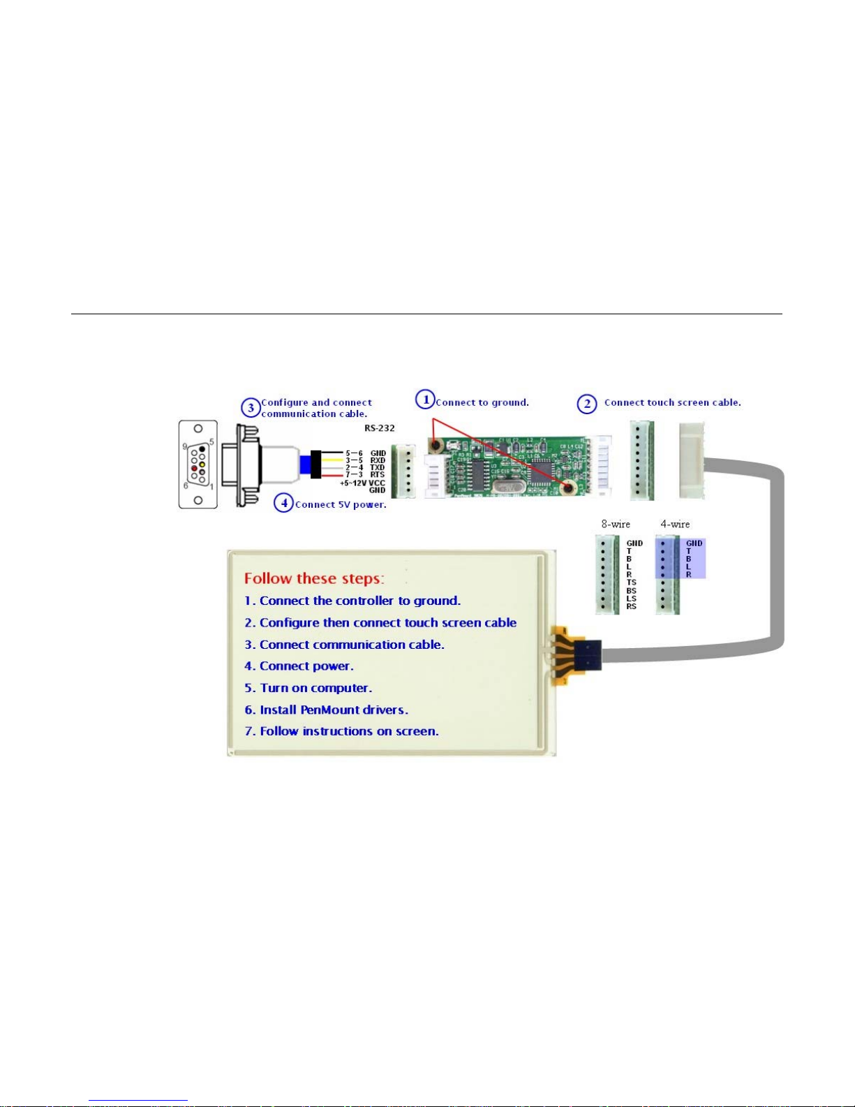
2.2. Installation Diagrams
2.2.1. The Connection of 9026BH Control Board (RS-232)
Page 10
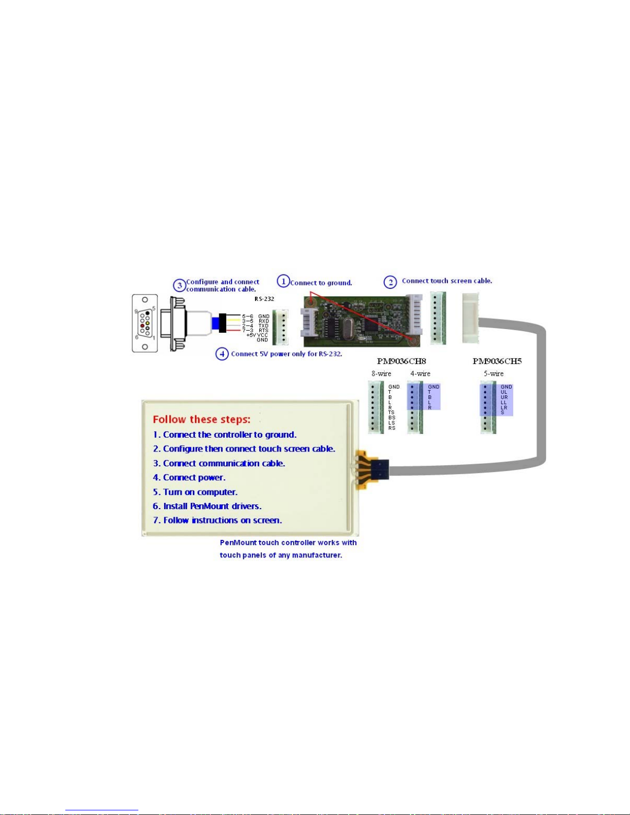
Chapter 3 Installing Software for 9000 Boards
4
2.2.2. The Connection of 9036CH Control Board (RS-232)
Page 11
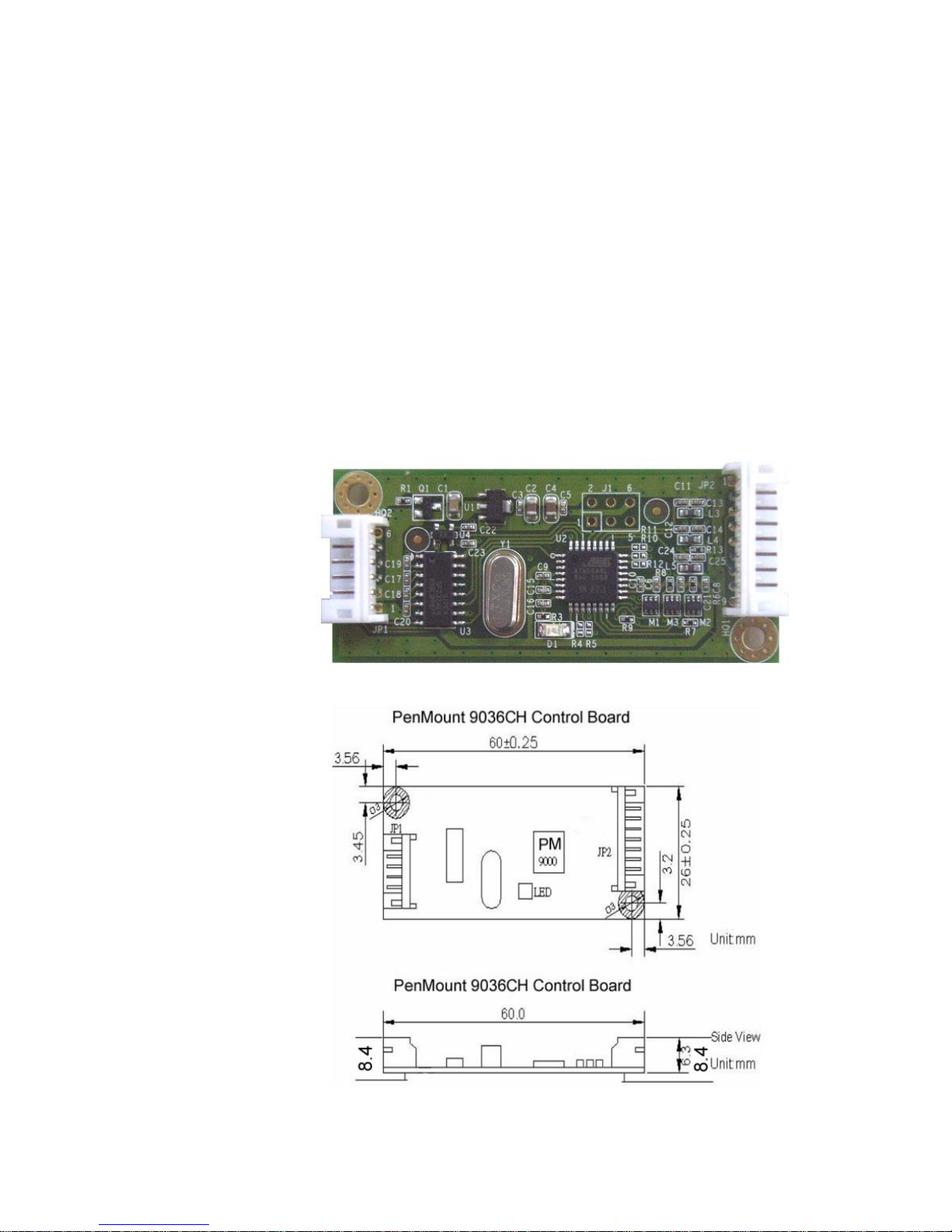
5
2.3. RS-232 Serial Boards (9000 Series)
PenMount 9000 control boards use the RS-232 serial interface. There are currently two
models in the 9000 Series. The general procedure for board installation is similar,
though hardware connection and configuration varies for each board.
2.3.1. PenMount 9036CH
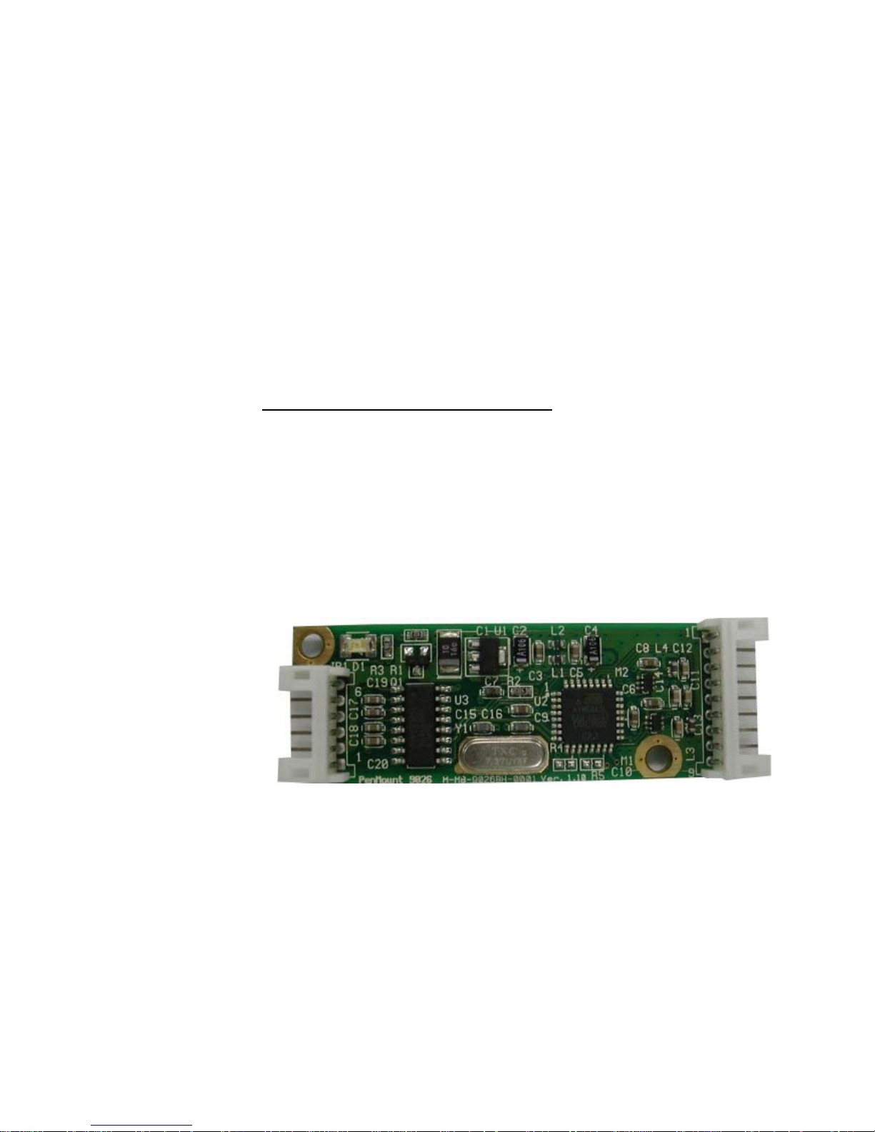
PenMount 9036CH control board is a RS-232 interface touch screen control
board that supports 4,8-wire or 5-wire touch screens. The size of the board
is 60 (L) x 26 (W) x 8.3 (H) mm and it has two connectors and four
dipswitches on-board. Follow the steps below to install 9036CH control
board.
Cut off the power of your computer and display, and then open the case of
the display or the system. Find the space on your system and attach the
control board to your system with screws. The control board has 3φ screw
holes in industrial standard.
PenMount 9036CH Touch screen Control Board Upside
PenMount 9036 Control Board Mechanical Diagram
Page 12
Install Drivers for 9000 Boards
6
Find the white 6-pin right angle connector (on the left in the photo above).
The power cable is pin 1 and pin 2. Solder the power and ground wire to the
system. The RS-232 cable is for pins 3 to 6. Attach the RS-232 cable’s
D-sub connector to a COM port at the back of the computer.
Find the white 9-pin right angle connector (on the right in the photo above).
Attach the female end of the touch screen cable to this connector. If you
have a 4-wire touch screen attach the cable to pins 1~5. If you have a 5-wire
touch screen attach the cable to pins 1~6. If you have an 8-wire touch
screen attach the cable to pins 1~9. Attach the male end of the cable to the
touch screen tail.
Mount your touch screen to the display.
Turn on power to the computer and the display.
Install the software drivers and utilities, then calibrate the touch screen. See
Chapter 3. Install Drivers for 9000 Boards on page 8.
2.3.2. PenMount 9026BH
The PenMount 9026BH control board is an RS-232 interface touch screen
control board that supports 4-wire and 8-wire touch screens. The size of the
board is 60 (L) x 20 (W) x 8.3 (H) mm and it has two connectors on-board.
Follow the steps below to install the 9026BH control board.
Cut off the power of your computer and display, then open the case of the
display or the system. Find the space on your system and attach the
control board to your system with screws. The control board has 3φ screw
holes in industrial standard.
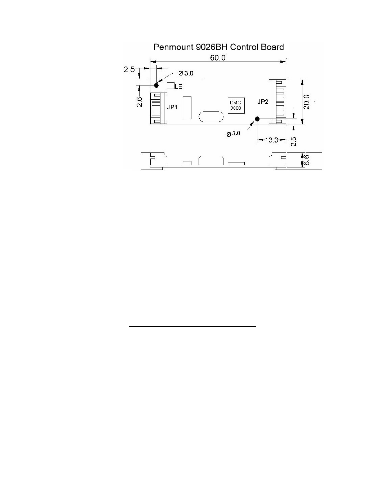
PenMount 9026BH Touch screen Control Board Upside
Page 13
Install Drivers for 9000 Boards
7
Unit:mm
PenMount 9026BH Control Board Mechanical Diagram
Find the white 6-pin right angle connector (on the left in the photo above).
The power cable is pin 1 and pin 2. Solder the power and ground wire to the
system. The RS-232 cable is from pins 3 to 6. Attach the RS-232 cable’s
D-sub connector to a COM port at the back of the computer.
Find the white 9-pin right angle connector (on the right in the photo above).
Attach the female end of the touch screen cable to this connector. If you
have a 4-wire touch screen attach the cable to pins 1~5. If you have an
8-wire touch screen attach the cable to pins 1~9. Attach the male end of the
cable to the touch screen tail.
Mount your touch screen to the display using tape or Velcro.
Turn on power for the computer and the display.
Install the software drivers and utilities, and then calibrate the touch screen.
See Chapter 3. Install Drivers for 9000 Boards on page 8.
Page 14

Install Drivers for 9000 Boards
8
Chapter 3. Install Drivers for 9000 Boards
This chapter describes how to install drivers and other software that will allow your PenMount
9000 Control Boards (RS-232) work with various operating systems.
3.1. Install PenMount DOS Driver
Before installing the DOS driver software, you must have the DOS system installed and
running on your computer. You must also have installed either PenMount 9026BH or
9036CH control board.
3.1.1. Install PenMount DOS Driver
PenMount DOS Driver version 2.10 diskette contains the following files:
INSTALL.EXE -- PenMount installation program
PM2.EXE -- PenMount Utility, to configure or test the PenMount
touch screen
PMOUSE.EXE -- Driver loader, to load or unload driver.
PMTSR.COM -- PenMount DOS Driver
PMOUSE.CFG -- The configuration file for PenMount DOS driver
README.TXT -- The file you're reading now.
PMINIT.BAT -- Reload DOS driver batch file
PMUNLOAD.BAT -- Unload DOS driver batch file
PMTEST.EXE -- PenMount driver test utility to verify PenMount
driver working.
MOUSETST.COM -- Mouse Test utility
If you have an older version of the PenMount DOS driver installed in your
system, please remove it first. PenMount 9000 control board has a 9-pin
D-sub connector. Before installation, plug into the COM port of PC. (e.g.
COM1, COM2, COM3 or COM4)
Follow the steps below to install the PenMount DOS driver.
Step 1
: Decompress the driver package. (e.g. C:\TEMP)
Step 2
: Go to the working directory. (E.g. cd \TEMP)
Step 3
: Run the installation program 'install.exe" at DOS prompt.
Step 4
: The install.exe will lead you to complete the installation.
Step 5
: Restart computer (Recommanded)
or
press 'ESC' key and issue 'SET
PENMOUNT=<penmount_installation_path>' at DOS prompt.
Step 6
: The PenMount driver will be loaded after restarting computer.
Page 15

Install Drivers for 9000 Boards
9
NOTE:
Environment Variable - PENMOUNT
The environment is variable, PENMOUNT needs PenMount driver
v2.10.
The installation program will put the command line 'SET
PENMOUNT=<penmount_install_path>' into the AUTOEXEC.BAT,
like:
SET PENMOUNT=C:\PM2 (e.g. PenMount installation path is
C:\PM2)
The driver can't be loaded, if the environment variable is not
configured properly and the utility can't be run. Issue the command
'set' at DOS prompt to check the environment variable.
Environment Variable - PATH
The installation program will put the installation path into the
environment PATH. You can run program in any working directory at
DOS prompt regardless of where the working directory is.
3.1.2. PenMount DOS Driver Functions
The PenMount DOS driver offers several functions. You can change the
settings with the following utilities:
1. PM2 Panel
Run the batch file 'PM2.EXE'. Type the command at DOS prompt:
PM2
Before running PM2, you must remove PenMount driver or another
mouse driver, if you have installed one.
There are several functions to select, and the launch key is in brackets.
(E.g. press '2' key to do calibration)
Use <arrow key> (up/down) to select, and <Enter> to launch the
following functions:
(1) Draw
(2) Calibrate
(3) Detect
(4) Configure
(5) Packet
(6) Help
(7) Exit
2. Draw
Run the 'Draw' in PM2 Panel, and use the arrow keys or hot keys (A~Y)
Page 16

Install Drivers for 9000 Boards
10
to choose one of 25 video modes.
Video modes:
mode width height colors
0Dh 320 200 16
13h 320 200 256
10Dh 320 200 32K
10Eh 320 200 64K
10Fh 320 200 16M
0Eh 640 200 16
10h 640 350 16
100h 640 400 256
12h 640 480 16
101h 640 480 256
110h 640 480 32K
111h 640 480 64K
112h 640 480 16M
103h 800 600 256
113h 800 600 32K
114h 800 600 64K
115h 800 600 16M
105h 800 768 256
116h 1024 768 32K
117h 1024 768 64K
118h 1024 768 16M
107h 1280 1024 256
119h 1280 1024 32K
11Ah 1280 1024 64K
11Bh 1280 1024 16M
There are several function keys in the drawing screen:
[ESC] - exit
[Space] - clear screen and information
[F1] - help, list the function keys
[F2] - style, toggle line or dot.
Line mode is default.
Dot mode is not to draw line between dot and next dot.
[F3] - frame, show / hide the frame
[F4] - dock, show / dock the status bar at bottom of screen
[F5] - pen color
There are 16 colors of pen color:
rainbow, blue, green, cyan, red, magenta, brown, lightgray,
darkgray, lightblue, lightgreen, lightcyan, lightred,
lightmagenta, yellow and white.
[F6] - highlight, highlight the dot in the line mode.
[F9] - camera, you can get the snapshot, and store it in bitmap file.
The filename is 'PM<HHMMSS>.BMP', <HHMMSS> is hour,
minute and second. The resolution of bitmap file is the
same as video mode, and the color depth is 4 bits.
(16colors)
Status bar:
Page 17

Install Drivers for 9000 Boards
11
640x480 - screen resolution (320x200, 640x480....etc)
S: - number of dots were received per second.
Pen - pen color
P: - the counter of received dots
D: - the counter of pen down
U: - the counter of pen up
(x,y) - current coordinate of dot
x:y: - minimum value of coordinate
X:Y: - maximum value of coordinate
3. Calibrate
Run the 'Calibrate' in PM2 Panel, and choose one of the 25 video
modes.
The purpose of calibration is to adjust the touch screen mapping to
meet the display screen properly.
You will be asked to select a video mode number. Select your display
mode by using keyboard to start calibration.
Touch the upper point, then touch the right point, bottom point and left
point, and press <Enter> key to pass the point. After calibration, the
calibrated data will be shown in the screen.
After calibration, we recommend you to do drawing test to verify the
touch screen and monitor mapped properly.
Function Keys:
[Enter] - pass current point
[F9] - camera, see above.
4. Detect
Detect PenMount automatically. You can press any key to abort the
detection.
Use the following list to detect PenMount:
COM1 (Base 03F8) (Baud 19200): IRQ 3, 4
COM2 (Base 03F8) (Baud 19200): IRQ 3, 4
COM3 (Base 03F8) (Baud 19200): IRQ 3, 4, 5, 6, 7, 8, 9, 10, 11, 12,
13, 14, 15
COM4 (Base 03F8) (Baud 19200): IRQ 3, 4, 5, 6, 7, 8, 9, 10, 11, 12,
13, 14, 15
COM1 (Base 03F8) (Baud 9600): IRQ 3, 4
COM2 (Base 03F8) (Baud 9600): IRQ 3, 4
COM3 (Base 03F8) (Baud 9600): IRQ 3, 4, 5, 6, 7, 8, 9, 10, 11, 12,
13, 14, 15
COM4 (Base 03F8) (Baud 9600): IRQ 3, 4, 5, 6, 7, 8, 9, 10, 11, 12,
13, 14, 15
Page 18

Install Drivers for 9000 Boards
12
If you cannot find the PenMount, come 'configure' to set your COM port.
5. Configure
COM Port: COM5~COM9 is for customized settings.
IRQ no.: IRQ3~IRQ15
I/O base: COM1~COM4 are fixed while COM5~COM9 are for
customization.
Baud: 19200 / 9600
Calibrate: left, right, top, and bottom point.
POMODE: the relationship between touch panel and monitor.
Beep Duration: beep duration time (0ms~5500ms), 0ms = turn off the
beep.
Beep Freq: beep frequency (20Hz ~10000 Hz)
Other configurations for customization in PenMount 9000:
jitter threshold
SSD threshold
Z threshold
pen-up threshold
digital filter
Function Key:
[ESC] - exit
[Tab] - toggle the fields
[up] - increase value
[down]- decrease value
[right]- increase value by 100 (Beep Freq)
[left]- decrease value by 100 (Beep Freq)
[Enter]- save configuration and exit
6. Packet
By using this function, you can get the touch data. Simply touch the
screen and you will see the data gotten.
The output format is as follows:
<counter> : counter of raw data
* : current dot
<raw data> : the raw data of touch
<coordinate> : the X, Y of A/D
<offset> : the offset between last dot
Function Key:
[ESC] - exit
7. Help
See 'README.TXT' file
8. Test
Page 19

Install Drivers for 9000 Boards
13
Before test, make sure the driver is loaded.
<1>. The test program is named 'MOUSETST.EXE'. You can run it with
parameter:
MOUSETST 18
The parameter is video mode number:
mode 18 (12h) : 640x480x16color
mode 19 (13h) : 320x240x256color
....
or run:
MOUSETST
to see what the parameters are
<2>. run pmtest.exe
<3>. edit
You can also run 'EDIT', the editor bundle in MS-DOS.
3.2. Install PenMount Windows 3.1 Driver
Before installing the Windows 3.1 driver software, you must have the Windows 3.1
system installed and running on your computer. You must also have PenMount Serial
Interface either 9026BH or 9036CH control board installed.
3.2.1. Install PenMount Windows 3.1 Driver
Contents of PenMount Windows 3.1 Driver folder are listed below.
COMPRESS.EXE
CTRLPAL.EX$
DETCMD.DL_
DIALOGUE
INSTALL.EXE — Installation program for PenMount Windows 3.1 driver
MPEN.38$
MPEN.DR$
SHOWCUR.EX$
STFSETUP.EX_
STFSETUP.IN_
UNINSTPM.EXE
VER.DL_
If you have an older version of PenMount Windows 3.1 driver installed in
your system, please remove it first. Follow the procedure below to install
the PenMount Windows 3.1 driver.
1. Make sure the Windows 3.1 system is installed in your computer. The
PenMount Windows 3.1 driver lets your touch screen coexist with a
mouse. If you wish to use a mouse and touch screen at the same time,
Page 20
Install Drivers for 9000 Boards
14
plug a mouse into one COM port and the PenMount touch screen to
another COM port before installing the PenMount Windows 3.1 driver.
2. Open the FILE MANAGER and under the MAIN group, run the
"Install.exe" software in the PenMount "WIN31" directory. The first
display shows "Welcome to install the PenMouse Driver." Click
"Continue" to begin installation.
3. Select the COM port you plugged the PenMount touch screen into, and
click "Continue."
4. The next screen is "Set the PORT address for com<x>”, select
"...[default]" or choose "User define". Then "Set the IRQ Number",
select "...[default]" or choose "User define." If you choose "User
define," key in an IRQ number. Click "Continue".
5. The last screen shows “Setup succeeded…" Click ‘EXIT’ to finish setup.
A new “PENMOUNT” group is generated after installing the PenMount
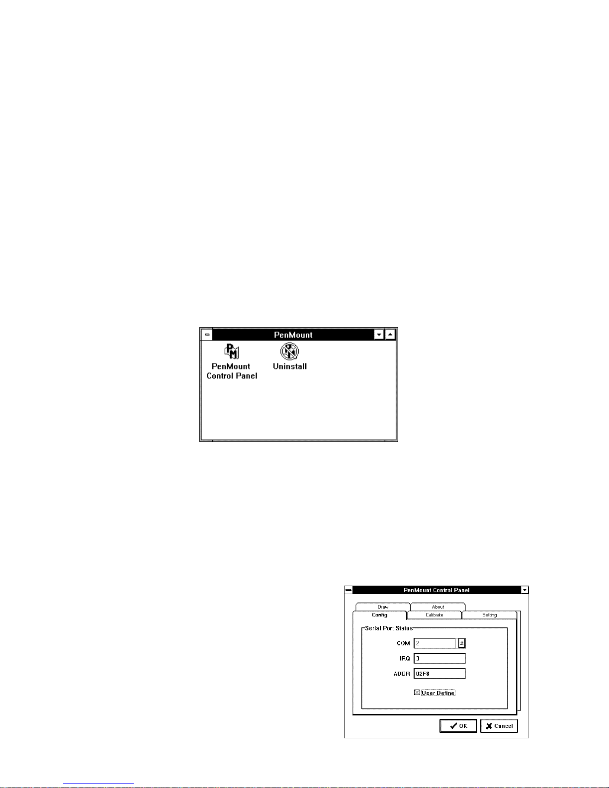
Windows 3.1 driver. Restart Windows 3.1. In the PenMount group, two
icons appear, “PenMount Control Panel” and “UNINSTALL,” The
PenMount Windows 3.1 driver is working concurrently with mouse.
3.2.2. PenMount Windows 3.1 Driver Functions
After installing PenMount the Windows 3.1 driver, the system generates a
Group named "PenMount" with two icons in the Group.
3.2.2.1. PenMount Control Panel
The functions of the PenMount Control Panel are described as
following:
Config
This sets the COM port,
IRQ number and base
address. Select COM
port and a default IRQ
number appears. If the
default IRQ number is
not what you require,
click “USER DEFINE”
and key-in an IRQ
number and base
address.
Page 21
Install Drivers for 9000 Boards
15
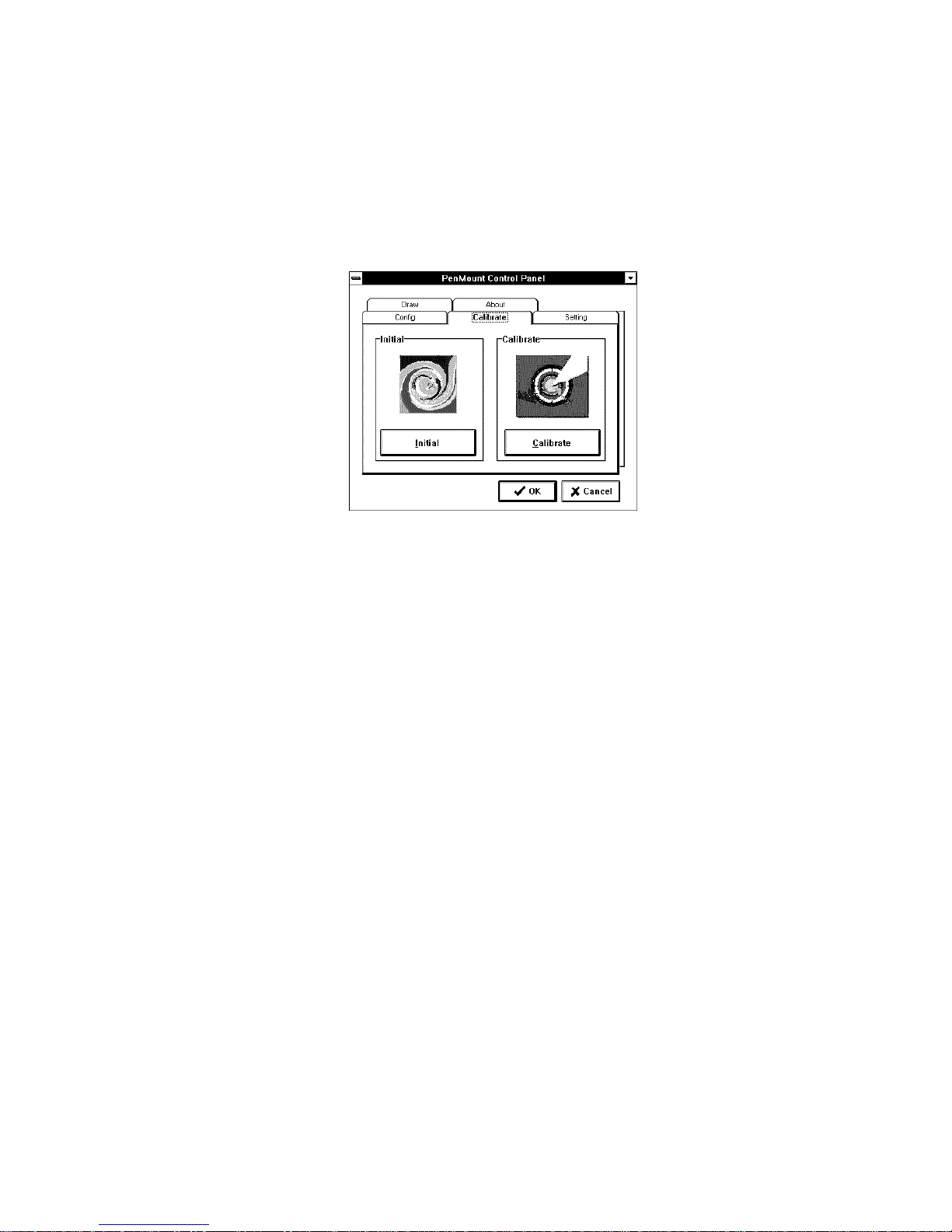
Calibrate
The two screen areas are Initial and Calibrate. Click Calibrate to
map the touch screen. The display shows a circle in the screen’s
upper-center, touch it. The display then shows a circle in the
right-center, bottom-center and left-center of the screen. Touch
these circles to map the touch screen to the display. Press the
Initial button to re-establish the connection with the control board
conveniently if the RS-232 serial port becomes disconnected.
Setting
This sets mouse performance, double click area, speed and testing
area.
Draw
This drawing function tests and demonstrates the touch screen.
Menu items include CLEAR and EXIT.
About
This displays the PenMount controller information.
3.2.3. Uninstall Windows 3.1 Driver
Click this icon and the system removes all utilities and the PenMount group
automatically.
3.3. Install PenMount Windows 95 Driver
Before installing the Windows 95 driver software, you must have the Windows 95
system installed and running on your computer. You must also have installed either
PenMount9026BH or 9036CH control board.
3.3.1. Install PenMount Windows 95 Driver
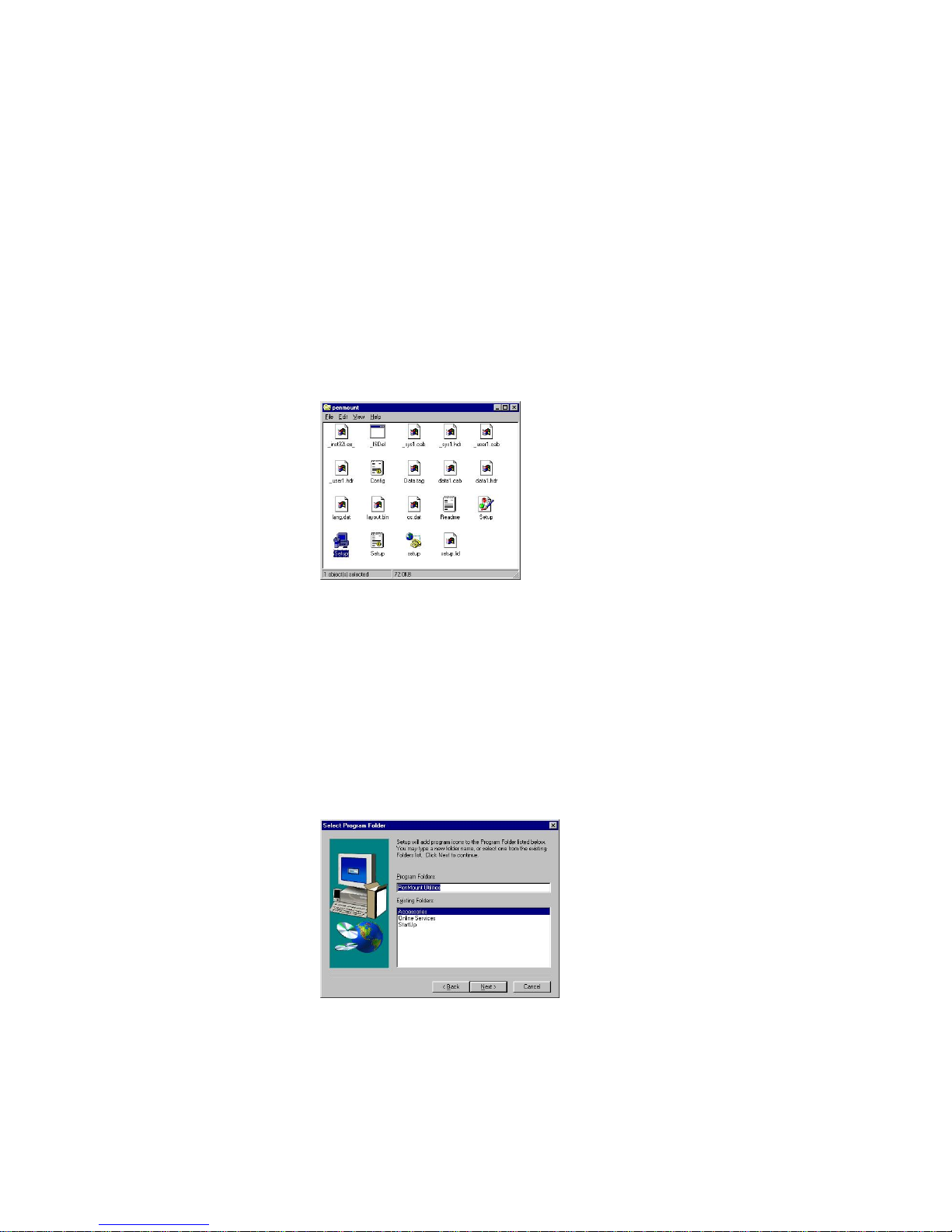
Contents of the PenMount Windows 95 driver folder are listed below.
_INST32I.EX _SETUP.EXE
_ISDEL.EXE OS.DAT
LANG.DAT _SETUP.DLL
SETUP.INS DATA.TAG
SETUP.INI _SYS1.HDR
Page 22
Install Drivers for 9000 Boards
16
_SYS1.CAB _USER1.HDR
_USER1.CAB SETUP.LID
SETUP.BMP DATA1.HDR
DATA1.CAB LAYOUT.BIN
CONFIG.INI README.TXT
If you have an older version of the PenMount Windows 95 driver installed in
your system, please remove it first. Follow the steps below to install the
PenMount Windows 95 driver:
1. When the system first detects the control board, a screen appears that
shows “Unknown Device.” Press Cancel.
2. Select "Run" in the "Start" menu.
3. Find "setup.exe" in the Windows 95 driver folder.
4. The PenMount logo appears, then "Installation Wizard," ‘PenMount
Utilities” and a "Welcome" message appear. Select “Next.”
5. The Software License Agreement screen and Information screen
appear. Select "Yes" and "Next".
6. The Choose Destination Location screen appears. To install PenMount
Utilities into the folder: C:\Program Files\PenMount\Win9x, select
"Next’ or modify the folder name to one you would like to use.
7. The Select Program screen appears. The default is "PenMount
Utilities". Select "Next” or change it.
8. The Start Copying Files screen appears. Select "Next" to copy files to
the system.
9. The Setup Complete screen appears. Select "Finish".
Page 23
Install Drivers for 9000 Boards
17
3.3.2. Configure PenMount Windows 95 Driver
After you install the software, PenMount Control Panel appears. In the
“Configure” panel set the correct COM port, IRQ number and base address.
Each of the functions in the PenMount Control Panel is explained in the
following section.
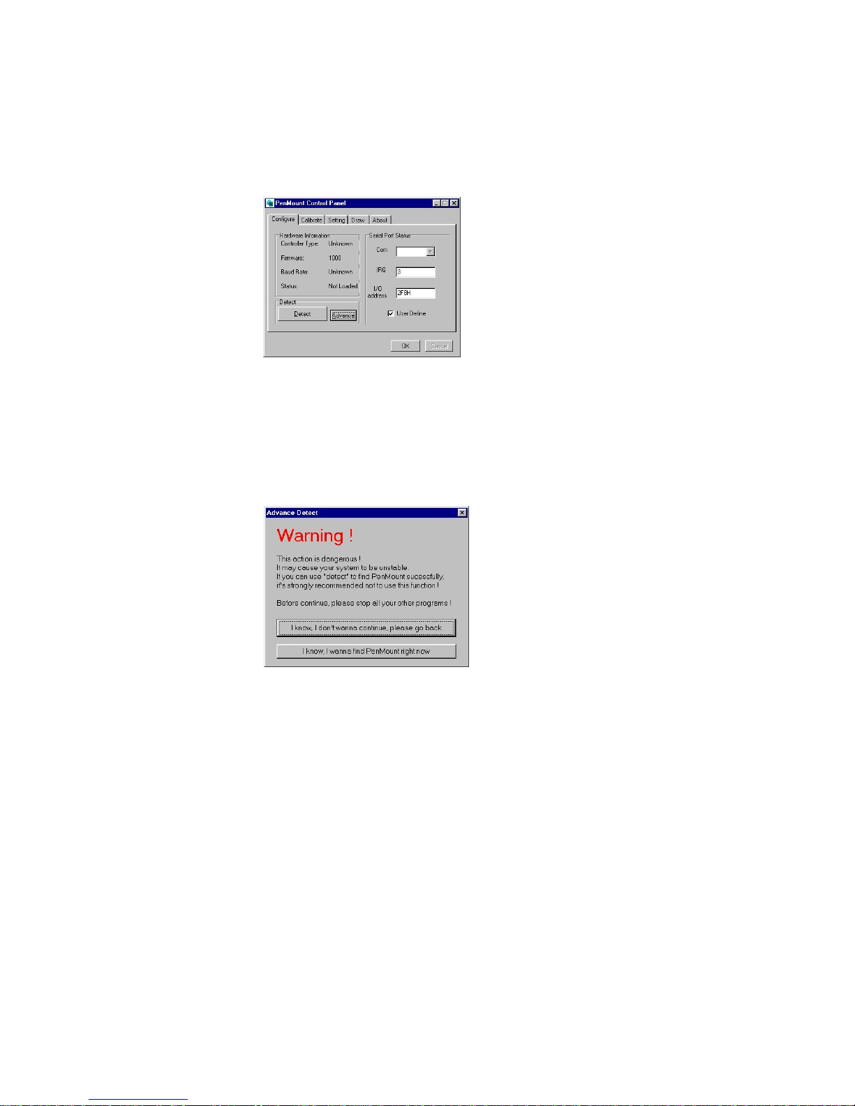
If your touch screen is connected to the COM1 or COM2, use the “Detect”
button to auto-detect the COM port. If you do not know which COM port is
connected, the “Advance” detect button helps you find the correct data.
Before selecting the “Advance” button you must close all other programs
first, otherwise it may cause these programs to crash. A third way to define
the COM port is to input the data directly by selecting “User Define”. After
making selections click OK and the system asks to reboot. Once the
system reboots, the PenMount touch screen should be working.
You must perform a calibration after rebooting the system. Select
‘PenMount Control Panel’ from ‘PenMount Utilities’ that is in ‘Programs’,
or select the ‘PM Control Panel’ by clicking the ‘PM’ icon in the notification
area. Refer to the PenMount Windows 95 Driver Functions below on how to
perform a calibration.
3.3.3. PenMount Windows 95 Driver Functions
Windows 95 driver functions are described below.
3.3.3.1. PenMount Control Panel
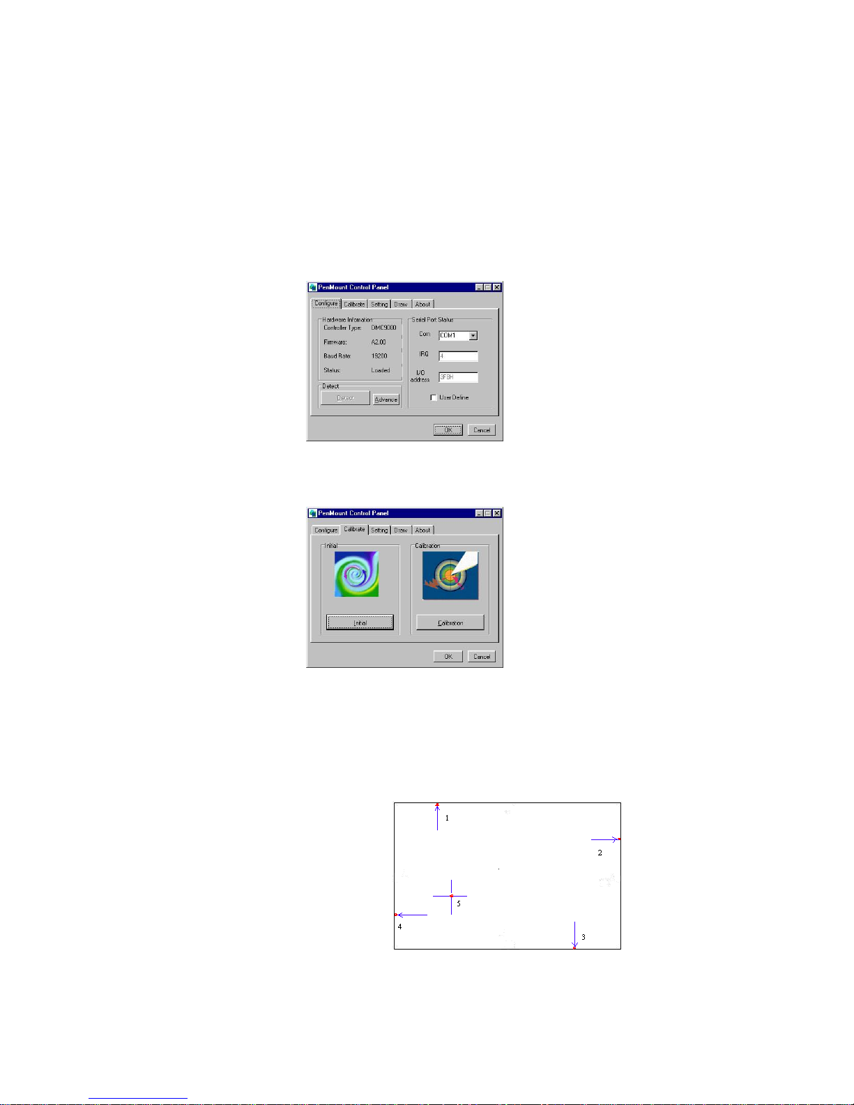
Configure
This item screen sets hardware connections, such as the RS-232
port, the IRQ number and the base address.
Controller Type
This shows the PenMount controller type, which is
DMC9000.
Page 24
Install Drivers for 9000 Boards
18
Baud Rate
Baud rate is fixed at 19200 for DMC9000.
Detect
Detect the connected port only if it is COM1 or
COM2.
Advance
This detects COM1 to COM4 port, detecting the
COM port and IRQ number in sequence. Note that
you must close all other programs running before
you select this function.
User Define
Lets you input this data from your keyboard.
Calibrate
This item provides the Initial and Calibration functions.
Initial
This button conveniently re-establishes connection
with the control board if the RS-232 serial port
becomes disconnected.
Calibration
This button maps the touch panel to the display. Click
Calibration and touch the five points in sequence to
calibrate.
Page 25
Install Drivers for 9000 Boards
19
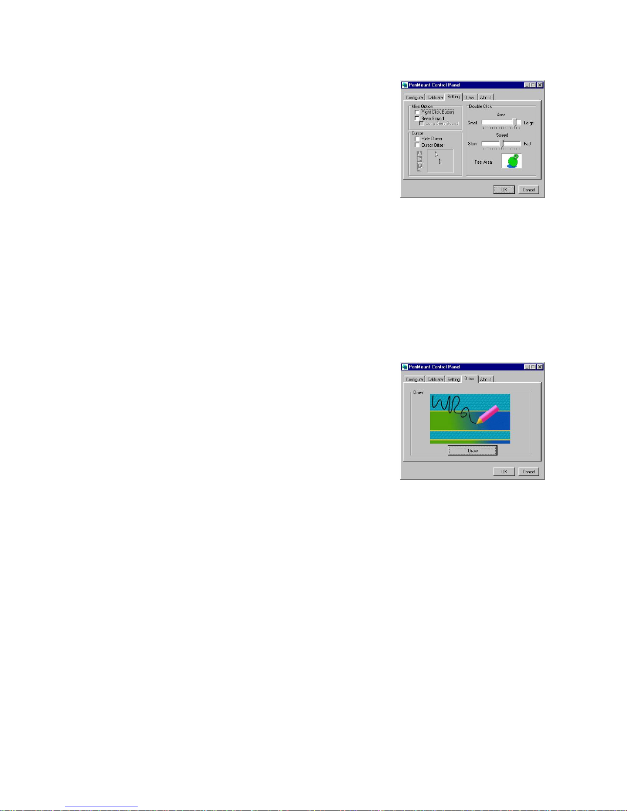
Setting
This item allows setting the
mouse and other interface
functions.
Misc. Option
Set the Right Click Button, Beep Sound and
Long Beep Sound.
Cursor
Set Hide Cursor or Cursor Offset. Use the arrow
keys to adjust cursor offset.
Double Click
Adjusts and tests double click area and speed.
Double click in the test area and the tumbler swings
back and forth.
Draw
Test or demonstrate PenMount
touch screen operation. The
display shows touch location. Click
Draw to start.
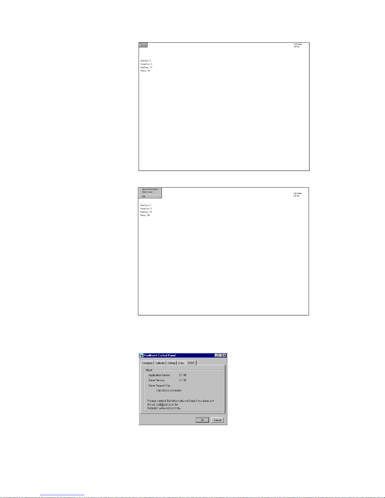
Touch the screen with your finger or a stylus and the drawing screen
registers touch activity such left, right, up, down, pen up, and pen
down.
Page 26
Install Drivers for 9000 Boards
20
Click
Clear Screen to clear the drawing.
About
This panel displays information about PenMount controller and this
driver version.
Page 27
Install Drivers for 9000 Boards
21
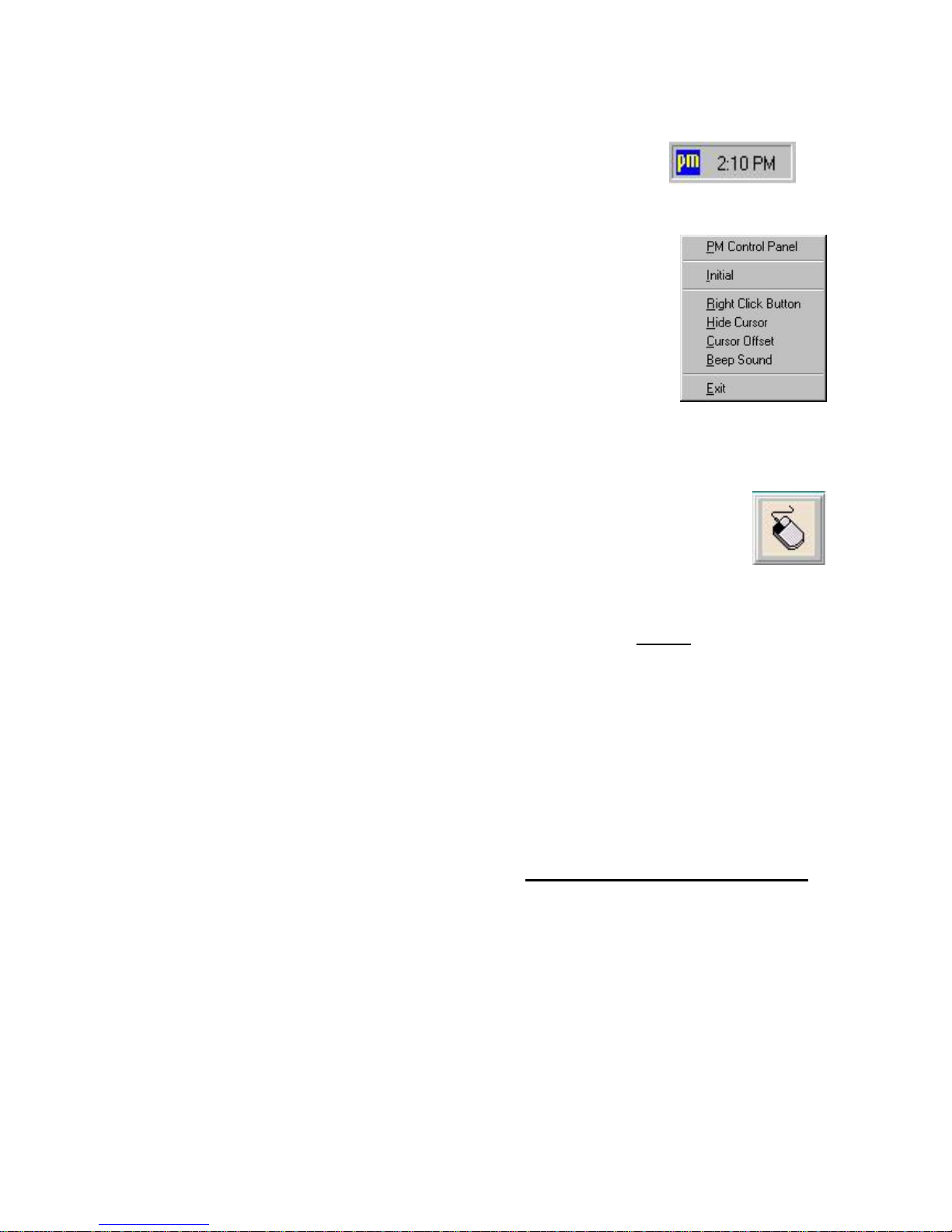
3.3.3.2. PenMount Monitor Menu Icon
PenMount monitor icon (PM) appears in
the notification area of Windows 95 system
when you turn on PenMount Monitor in
PenMount utilities.
PenMount Monitor has the following
functions.
Initial
This resets the PenMount controller chipset. Normally,
you do not need to use this function. The Windows 95
driver checks the controller chipset automatically.
Right
Click
Button
When you select this function, a mouse
icon appears in the right-bottom of the
screen. Click this icon to switch between
Right and Left Button functions.
Hide
Cursor
Set to hide or show cursor.
Cursor
Offset
Adjust the cursor offset. See Setting of PenMount
Control Panel on page 19.
Beep
Sound
Turn on or off the beep.
Exit
Exit PenMount Monitor function.
3.3.3.3. PenMount Rotating Functions
PenMount Windows 95 Driver supports several display rotating
software packages. See Chapter 4. Driver Software Functions
on page 51 for more information. PenMount drivers for Windows 95,
98/ME, NT, and 2000/XP/2003/VISTA/7 support the following
display rotating software packages:
- Portrait’s Pivot Screen Rotation Software
- ATI Display Driver Rotate Function
- nVidia Display Driver Rotate Function
- SMI Display Driver Rotate Function
- Intel Display Driver Rotate Function
Configure Rotate Function
1. Install the rotation software package.
Page 28
Install Drivers for 9000 Boards
22
2. Choose rotate function (0°, 90°, 180°, 270°) in the 3
rd
party
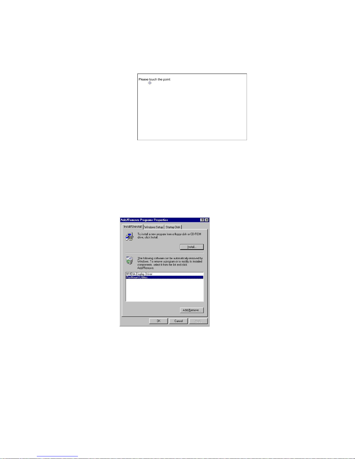
software. The calibration screen appears automatically. Touch
this point and rotation is mapped.
NOTE: Rotate function will be disable if you use Monitor
Mapping.
3.3.4. Uninstall PenMount Windows 95 Driver
1. Exit PenMount Monitor (PM) in the notification area.
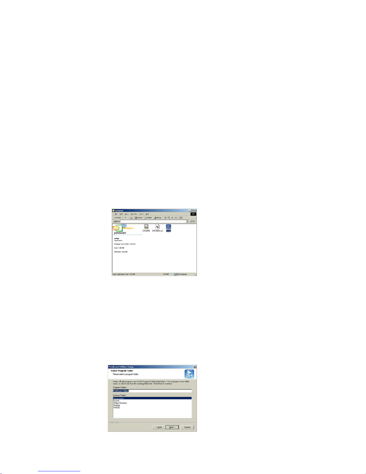
2. From ‘PenMount Utilities’ in ‘Programs’, select the ‘Uninstall’ utility.
3. This message shows up: “Are you sure you want to completely
remove ‘PenMount Utilities’ and all its components?”
4. Select ‘Yes’ to remove PenMount Windows 95 Driver.
5. Reboot system and PenMount Windows 95 Driver is removed from
the system.
Page 29
Install Drivers for 9000 Boards
23
3.4. Install PenMount Windows 98/ME Driver
Before installing PenMount Windows 98/ME Driver, you must have had Windows
98/ME system installed in your computer. You must also have installed either
PenMount 9026BH or 9036CH control board.
3.4.1. Install PenMount Windows 98/ME Driver
The content of PenMount Windows 98/ME Driver folder is listed below:
SETUP.EXE
DMC9000.INF
DMC9000.VXD
If you have an older version of PenMount Windows 98/ME Driver installed
in your system, remove it first and follow the steps below to install
PenMount Windows 98/ME Driver.
When system first detects the control board, a screen appears that shows
“Unknown Device”. Do not use this hardware wizard. Press Cancel.
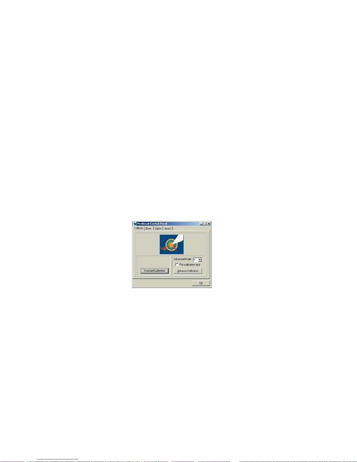
Install PenMount Windows 98/ME Driver to your system from the
CD-ROM:
A welcome message for the PenMount utilities setup program appears.
Select “Next”.
A Software License Agreement screen appears. Select "Yes".
A information screen appears. Select "Next".
Choose Destination Location screen appears. To install PenMount utilities
into the folder: C:\Program Files\PenMount\Win9x, select "Next” or modify
the folder name to one you would like to use.
Select Program Folder screen appears. The default is "PenMount
Utilities". Select "Next” or change it.
Page 30
Install Drivers for 9000 Boards
24
Start Copying Files screen appears. Select "Next" to copy files to the
system.
Setup Complete screen appears. Select "Finish". “Restarting Windows”
screen appears, choose “Yes, I want to restart my computer now,” and
“OK”.
3.4.2. Configure PenMount Windows 98/ME Driver
Upon restarting, the computer finds the new 9000 control board
automatically. The touch screen is connected but not calibrated. Follow the
procedures below to run the calibration.
1. After installation, click PenMount Monitor icon “PM” in the notification
area.
2. When PenMount Control Panel appears, click “Calibrate”.
3.4.2.1. PenMount Control Panel
The functions of PenMount Control Panel are explained in the
following sections.
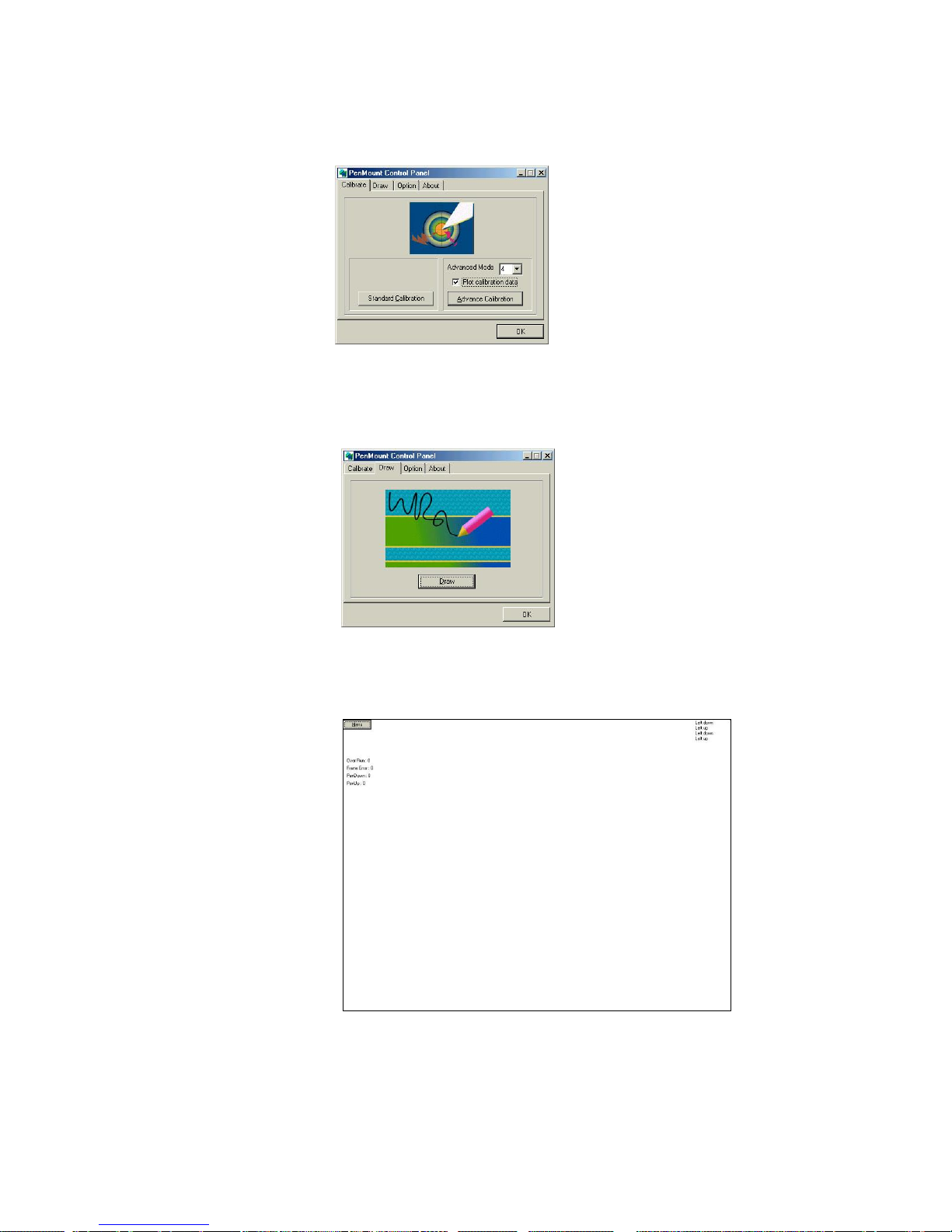
Calibrate
This function offers two ways to calibrate your touch screen.
‘Standard Calibration’ adjusts most touch screens. ‘Advanced
Calibration’ adjusts aging touch screens.
Standard Calibration
Click this button and arrows appear
pointing to red squares. Use your finger
or stylus to touch the red squares in
sequence. After the fifth red dot of
calibration is complete. To skip, press
‘ESC’.
Advanced Calibration
Advanced Calibration uses 4, 9, 16 or
25 points to effectively calibrate touch
panel linearity of aged touch screens.
Click this button and touch the red
squares in sequence with a stylus. To
skip, press ‘ESC’.
NOTE: The older a touch screen is, the more Advanced Mode
calibration points it needs. Use a stylus to make the
Advanced Calibration for the best accuracy.
Page 31
Install Drivers for 9000 Boards
25
Plot Calibration Data
Check this function and a touch
panel linearity comparison graph
shows up when you finish the
Advanced Calibration. The black
lines reflect the ideal linearity
assumed by PenMount’s application
program while the blue lines show
the approximate linearity calculated
by PenMount’s application program
as the result of user’s execution of
Advance Calibration.
Draw
To test or demonstrate PenMount touch screen operations, the
display shows touch location. Click Draw to start.
Touch the screen with your finger or a stylus and the drawing screen
registers touch activity such left, right, up, down, pen up, and pen
down.
Click Clear Screen to clear the drawing.
Page 32
Install Drivers for 9000 Boards
26
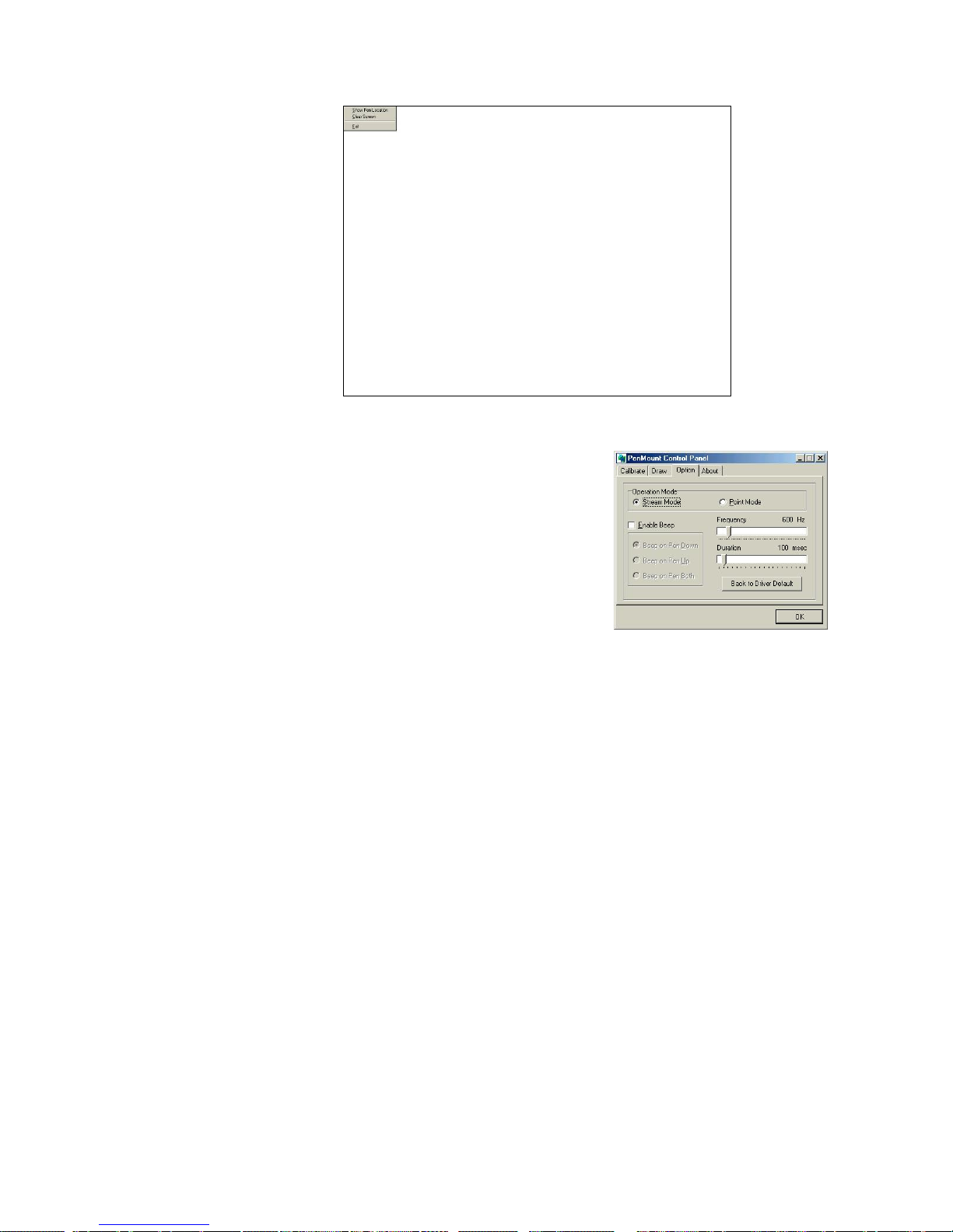
Option
This panel function supports two
modes - Operation Mode and
Beep Sound Mode – which allows
configuration for specific touch
screen applications, such as
point-of-sales (POS) terminals.
Operation Mode
This mode enables and disables the mouse’s
ability to drag on-screen icons—useful for
configuring POS terminals.
Stream Mode – Select this mode and the
mouse functions as normal and allows
dragging of icons.
Point Mode – Select this mode and the
mouse only provides a click function, and
dragging is disabled.
Beep Sound Mode
Enable Beep Sound – turns beep function on
and off
Beep on Pen Down – beep occurs when pen
comes down
Beep on Pen Up – beep occurs when pen is
lifted up
Beep on both of Pen Down/Up – beep
occurs on both
Beep Frequency – modifies sound frequency
Beep Duration – modifies sound duration
Page 33
Install Drivers for 9000 Boards
27
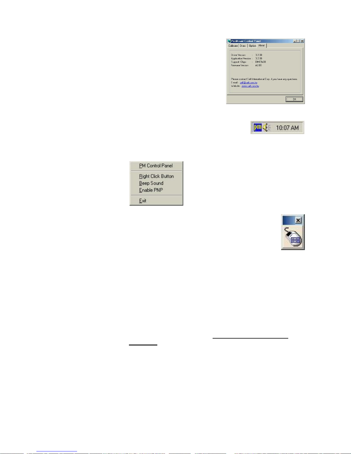
About
This panel displays information
about PenMount controller and this
driver version.
3.4.2.2. PenMount Monitor Menu Icon
PenMount monitor icon (PM) appears in the
notification area of Windows 98/ME system
when you turn on PenMount Monitor in PenMount Utilities.
PenMount Monitor has the following functions.
Right Click Button
When you select this function, a
mouse icon appears in the
right-bottom of the screen. Click
this icon to switch between Right
and Left Button functions.
Beep Sound
Turn on or of the beep.
Enable PNP
Turn on or turn off PNP. When it is not
selected, PNP is off and the RS-232 transfer
signal continues when unplugging and
plugging the cable into the serial port.
Exit
Exit PenMount Monitor function.
3.4.2.3. PenMount Rotating Functions
PenMount Windows 98/ME Driver supports several display rotating
software packages. Please see Chapter 4. Driver Software
Functions on page 51 for more information. PenMount drivers for
Windows 95, Windows 98/ME, as well as 2000/XP/2003/VISTA/7/8
support the following display rotating software packages:
- Portrait’s Pivot Screen Rotation Software
- ATI Display Driver Rotate Function
- nVidia Display Driver Rotate Function
- SMI Display Driver Rotate Function
- Intel Display Driver Rotate Function
Page 34
Install Drivers for 9000 Boards
28
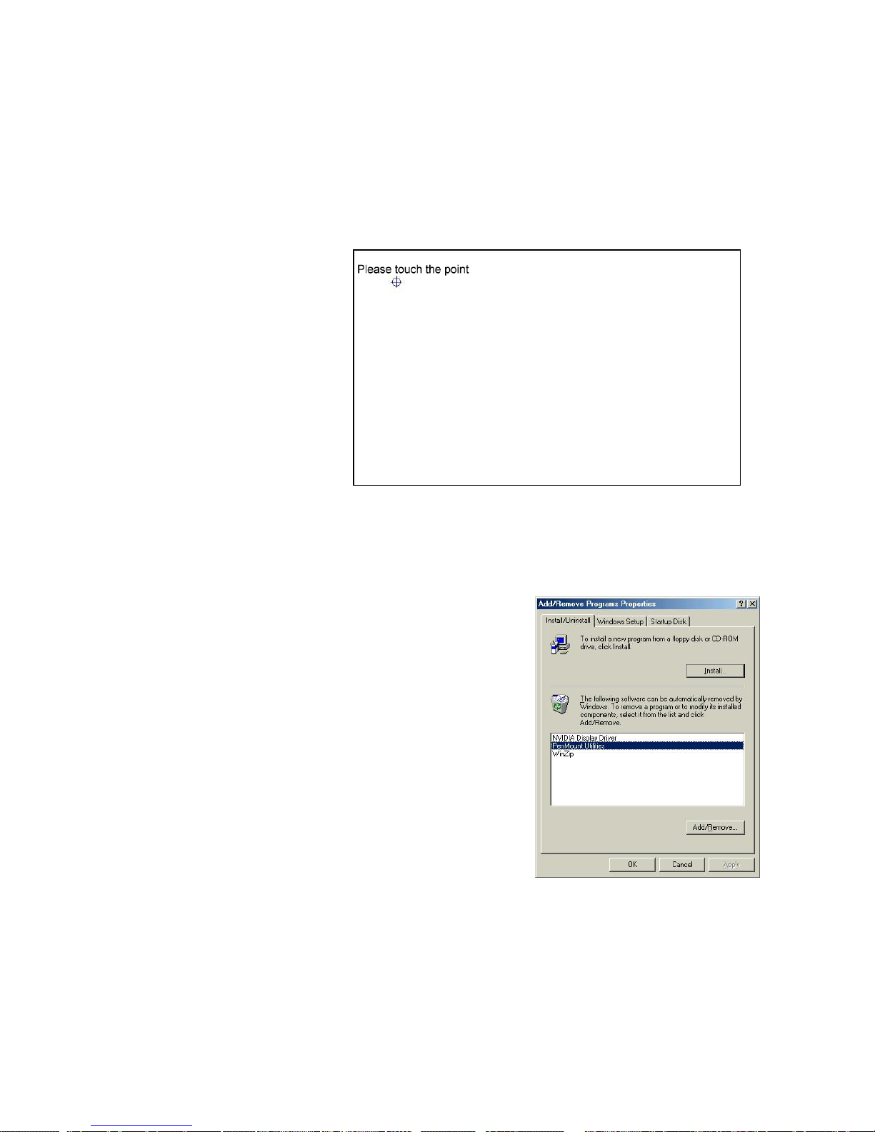
Configure Rotate Function
1. Install the rotation software package.
2. Choose rotate function (0°, 90°, 180°, 270°) in the 3rd party
software. The calibration screen appears automatically. Touch
this point and rotation is mapped.
NOTE: Rotate function will be disable if you use Monitor
Mapping.
3.4.3. Uninstall PenMount Windows 98/ME Driver
1. Exit PenMount Monitor (PM)
from the notification area.
2. Select ‘Uninstall’ utility from
‘Programs’ of ‘PenMount
Utilities’.
3. A message appears: “Are you
sure you want to completely
remove ‘PenMount Utilities’ and
all its components?”
4. Select ‘Yes’ to remove PenMount
Windows 98/ME Driver.
5. Reboot system and PenMount
Windows 98/ME Driver is removed from system.
Page 35
Install Drivers for 9000 Boards
29
3.5. Install PenMount Windows NT Driver
Before installing PenMount Windows NT Driver, you must have had Windows NT
system installed and run in your computer. You must also have PenMount Serial
Interface either 9026BH or 9036CH control board installed.
3.5.1. Install PenMount Windows NT Driver
Content of PenMount Windows NT Driver folder is listed below.
_USER1.HDR _ISDEL.EXE
_SETUP.DLL _SYS1.CAB
_SYS1.HDR _USER1.CAB
_INST32I.EX CONFIG.INI
DATA.TAG DATA1.CAB
DATA1.HDR INFO.TXT
LANG.DAT LAYOUT.BIN
LICENSE.TXT OS.DAT
README.TXT SETUP.LID
SETUP.INS SETUP.INI
SETUP.EXE SETUP.BMP
If you have an older version of PenMount Windows NT Driver installed in
your system, remove it first and follow the steps below to install PenMount
Windows NT Driver.
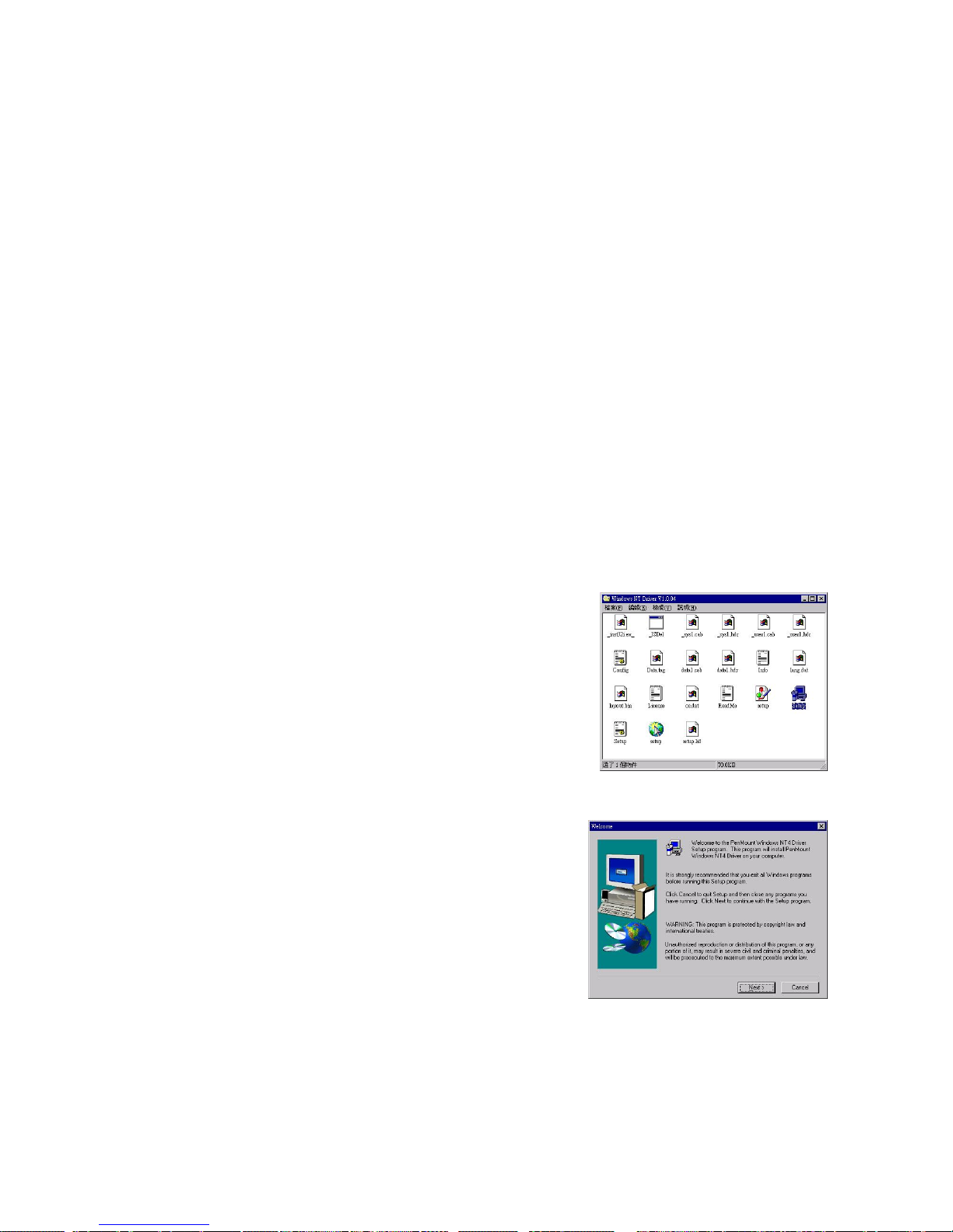
1. Insert PenMount driver CD-ROM.
Go to the Windows NT Driver folder.
Click setup.exe.
2. A welcome message for the
PenMount setup program appears.
Select “Next”.
Page 36
Install Drivers for 9000 Boards
30
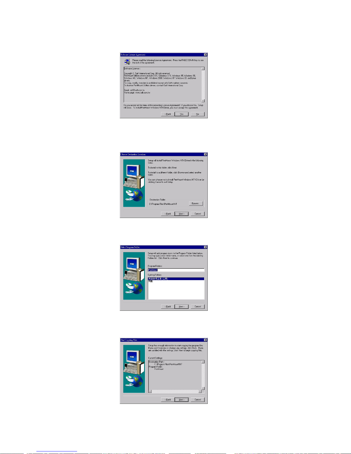
3. Software License Agreement screen appears. Select "Yes".
4. Choose Destination Location screen appears. Then install
PenMount utilities into folder: C:\Program Files\PenMount\NT. Select
"Next’ or modify the folder name to one you would like to use.
5. Select Program Folder screen appears. The default is "PenMount
Utilities". Select "Next” or change it.
6. Start Copying Files screen appears. Select "Next" to copy files to the
system.
Page 37
Install Drivers for 9000 Boards
31
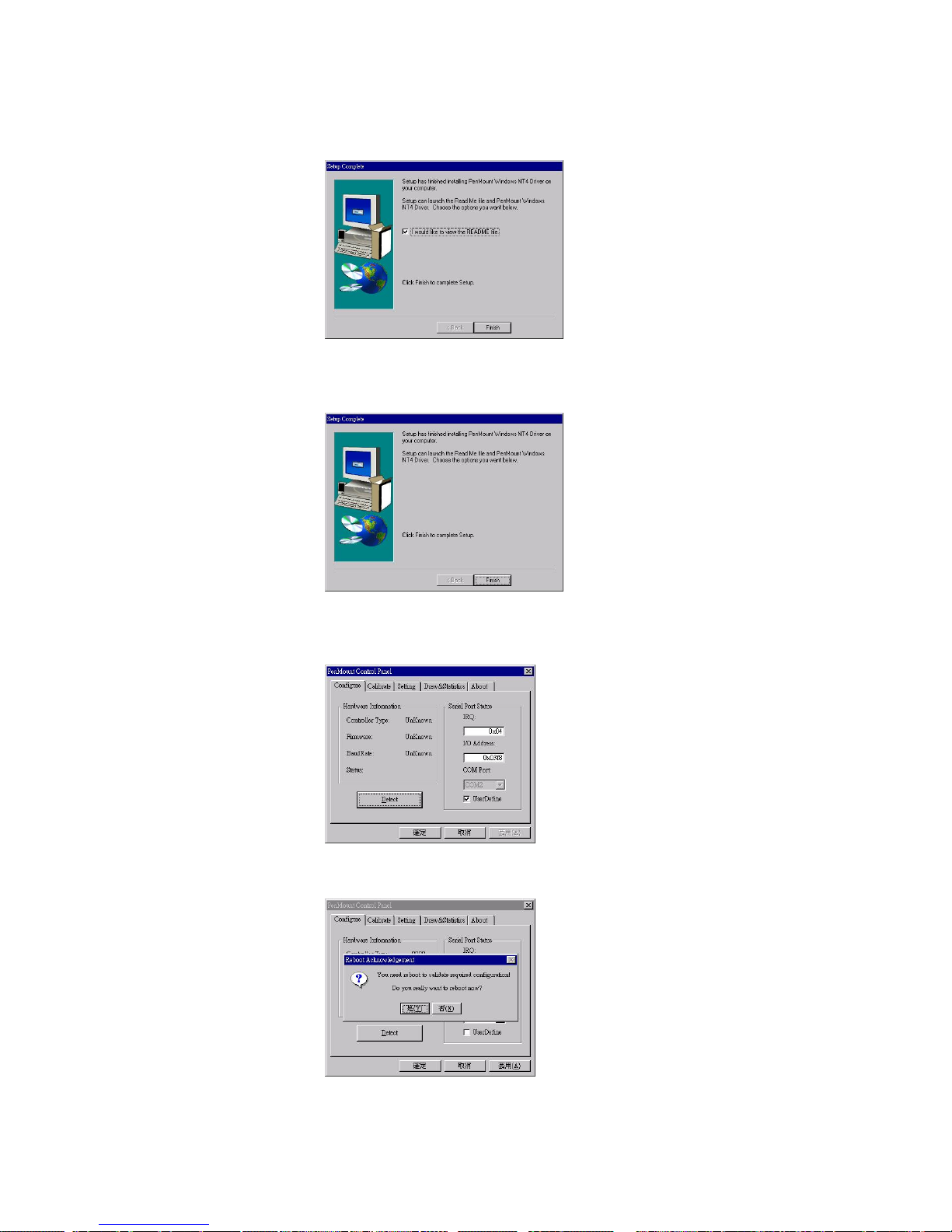
7. Setup Complete screen appears. Check “I would like to view the
README file”. Select "Finish".
8. README file appears. After reading, cancel the window and press
"Finish" again.
9. PenMount Control Panel appears. In Configure panel press the
Detect button to auto-detect the correct COM port.
10. Reboot the system.
Page 38
Install Drivers for 9000 Boards
32
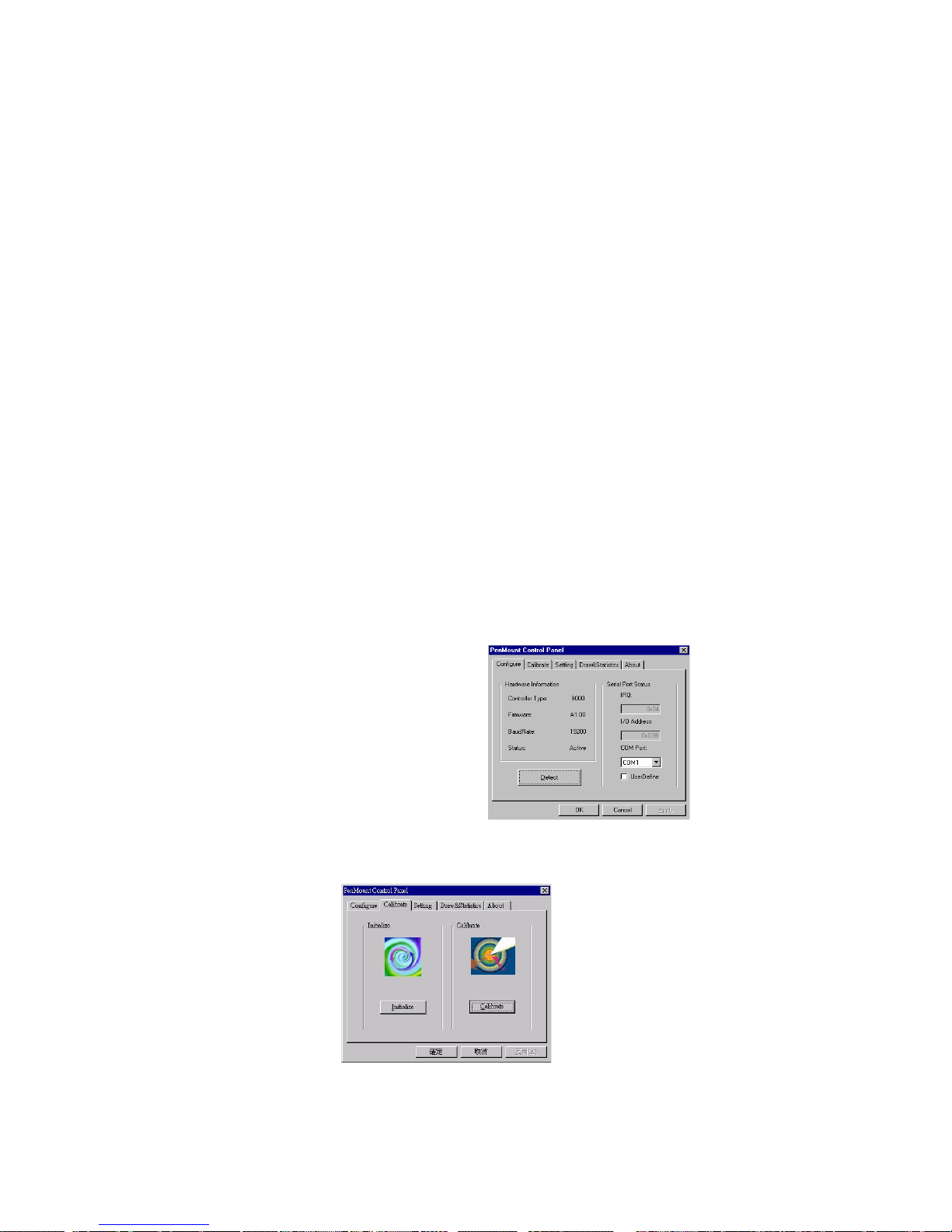
11. After rebooting, go to “Programs”, “PenMount Utilities”, and then
“PenMount Control Panel”. The PenMount Control Panel appears.
Select Calibrate and begin calibration to adjust the mapping of the
touch screen and display.
3.5.2. Configure PenMount Windows NT Driver
While rebooting, the computer finds the new 9000 control board
automatically. The touch screen is connected but not calibrated. Follow the
procedures below to carry out calibration.
3.5.2.1. PenMount Control Panel
You can access the PenMount control panel from the “PM” icon in
the notification area. The functions of PenMount Control Panel are
explained below.
Configure
This item configures the driver to use with the hardware by setting
COM port, IRQ number and I/O address.
Controller Type
This shows the PenMount controller type, which
is DMC9000.
Baud Rate
Baud rate is fixed at 19200 for DMC9000.
Detect
Click this button to auto-detect COM port, IRQ
number, or base address.
User Define
Lets you input this data from your keyboard.
Calibrate:
This item provides Initialize and Calibration functions.
Page 39
Install Drivers for 9000 Boards
33
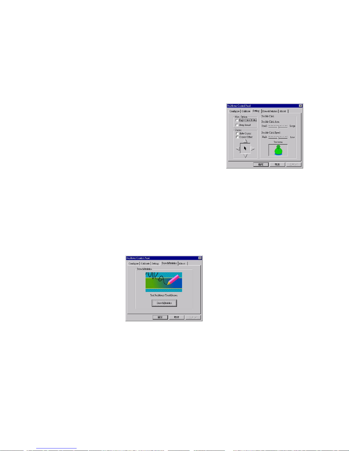
Initialize
This button re-establishes connection with the control
board if the RS-232 serial port becomes disconnected.
Calibration
This button maps the touch panel to the display. Click
Calibration and touch the five points in sequence to
calibrate.
Setting
This item allows setting the mouse
and other interface functions.
Misc. Option
Sets the Right Click Button and Beep Sound
Cursor
Sets Hide Cursor or Cursor Offset. Press the
four triangles with a stylus to adjust cursor offset.
Double Click
Adjusts and tests double click area and speed.
Double click in the test area and the tumbler
swings back and forth.
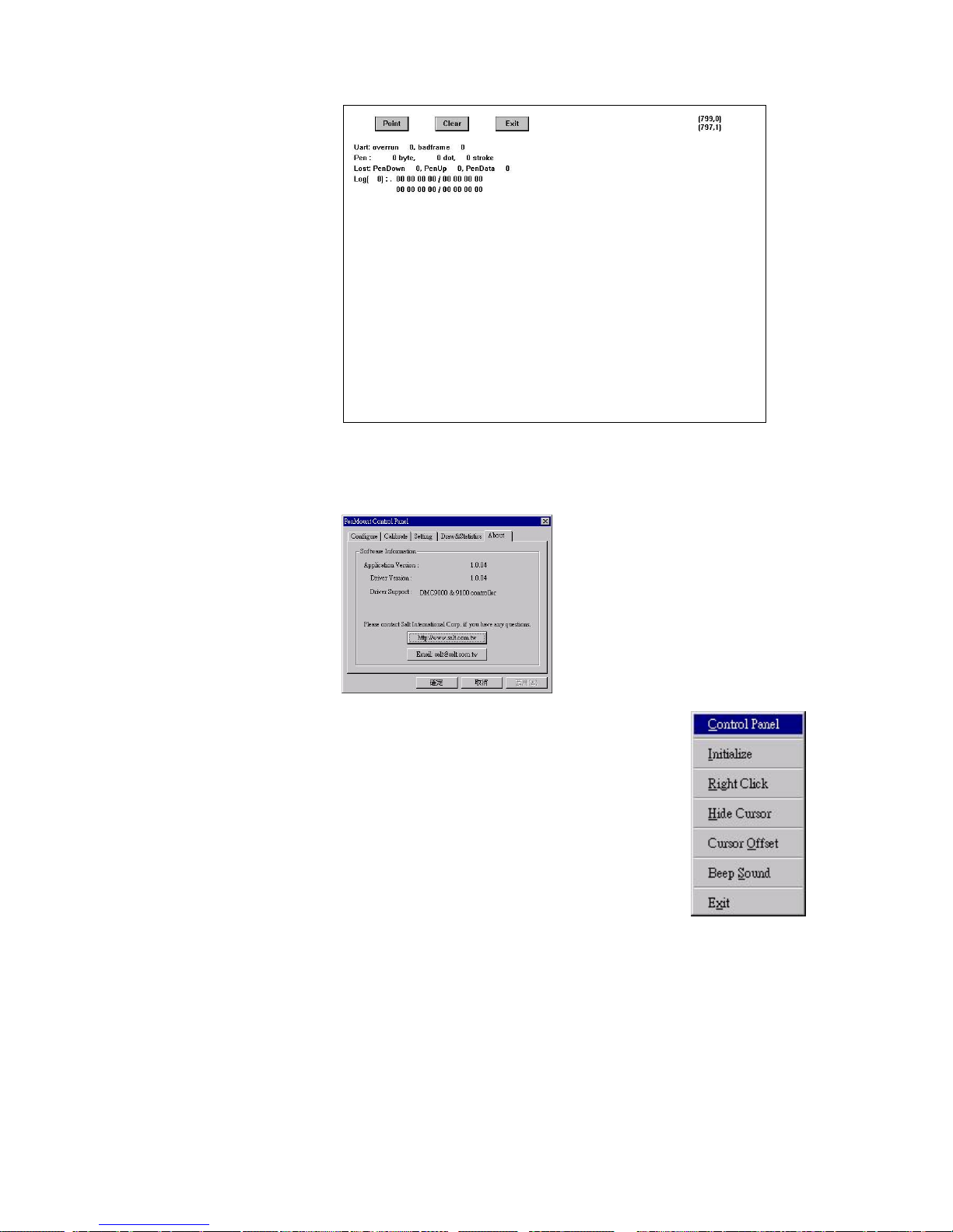
Draw & Statistics
To test or demonstrate PenMount touch screen operations. The
display also shows touch location. Click Draw & Statistics to start.
Page 40
Install Drivers for 9000 Boards
34
About
This panel displays information about PenMount controller and this
driver version.
3.5.2.2. PenMount Monitor Menu Icon
PenMount monitor icon (PM) appears in the
notification area of Windows NT system when
you turn on PenMount Monitor in PenMount
utilities. PenMount Monitor has the following
functions.
Initialize
This resets the PenMount controller chipset.
Normally, you do not need to use this function
because the Windows NT driver checks the
controller chipset automatically.
Right Click
When you select this function, a mouse icon
appears in the right-bottom of the screen. Click
this icon to switch between Right and Left
Button functions.
Page 41

Install Drivers for 9000 Boards
35
Hide Cursor
Set to hide or show cursor.
Cursor Offset
Adjust the cursor offset. See
Setting of the PenMount Control Panel on page
33.
Beep Sound
Turn on or of the beep.
Exit
Exits PenMount Monitor function.
3.5.2.3. PenMount Rotating Functions
PenMount Windows NT Driver supports several display rotating
software packages. Please see Chapter 4. Driver Software
Functions on page 51 for more information. PenMount drivers for
Windows 95, Windows 98/ME as well as Windows
2000/XP/2003/VISTA/7/8 support the following display rotating
software packages:
- Portrait’s Pivot Screen Rotation Software
- ATI Display Driver Rotate Function
- nVidia Display Driver Rotate Function
- SMI Display Driver Rotate Function
- Intel Display Driver Rotate Function
Configure Rotate Function
- Install the rotation software package.
- Choose rotate function (0°, 90°, 180°, 270°) in the 3rd party
software. The calibration screen appears automatically.
Touch this point and rotation is mapped.
NOTE: Rotate function will be disable if you use Monitor
Mapping.
3.5.3. Uninstall PenMount Windows NT Driver
- Exit PenMount Monitor (PM) in the notification area.
- From ‘PenMount Utilities’ in ‘Programs’, select the ‘Uninstall’ utility.
- This message appears: “Are you sure you want to completely remove
‘PenMount Utilities’ and all its components?”
- Select ‘PenMount Windows NT Driver’ and click Remove.
Page 42

Install Drivers for 9000 Boards
36
- Reboot system and PenMount Windows NT Driver is removed from
system.
3.6. Install PenMount Windows Universal Driver (for
2000/XP/XPT/XPE/2003/VISTA/7/WES7/2008/8)
Before installing PenMount Windows Universal Driver, you must have had installed
one of the operating systems from Windows 2000/ XP/ XPT/ XPE/ 2003/ VISTA/ 7/
WES7/ 2008/ 8 in your computer, and either PenMount 9036CH or 9026BH must have
been installed.
Before installing PenMount Windows Universal driver V2.4.0.306, you may modify the
default options from \PenMount Universal Driver V2.4.0.306\Driver\Install.ini:
Install USB 1. Install PenMount USB driver.
0. Uninstall PenMount USB driver.
COM 1. Install PenMount RS232 driver.
0. Uninstall PenMount RS232 driver.
MMonitor 1. Install PenMount driver for multi- device recognition.
0. Uninstall PenMount driver for multi- device recognition.
ENUM 1. Install PenMount driver for Non- pnp device recognition.
0. Uninstall PenMount driver for Non- pnp device recognition.
Option TouchReport 1. The default setting of Windows 2k/XP/Vista/7 is mouse mode.
2. The default setting of Windows 2k/XP is mouse mode;
the default setting of Windows 7/ Vista is digitizer mode.
EdgeOffset 0,5,10,15,20,25,30 are the default values for edge
compensation.
Smoothing 1. Turn on the smoothing function.
0. Turn off the smoothing function.
Operation The default settings of operating mode:
0, Pen Input Emulation
1, Click on Touch
2, Mouse Emulation
3, Click on Release
CalibOffset This function is unable to be modified.
RBtnPressNHold 0. Turn on long- pressed right key function.
1. Turn off long- pressed right key function.
Serial ScanAllPorts 1. Turn on “Scan All Ports” to confirm PenMount RS232 device.
0. Turn off “Scan All Ports” to confirm PenMount RS232 device.
COM3=xxxx,yyyy To set up the permanent system COM port for PenMount RS232
driver.
COM3- to correct it to be correspondent with the actual COM
PORT.
xxxx- the supporting item number: 9000/ 6000 or PCI.
yyyy- the baud rate of 6000 or 9000 is 19200 or 9600;
baud rate 38400 is only for PCI items.
# Please note that the data above must be correct, so that the
device can just work normally, and ENUM must be set as 1.
Page 43
Install Drivers for 9000 Boards
37
Example:
COM1= PCI, 38400
# Permanently install PCI RS232 38400bps at COM1
COM3= 6000,19200
#Permanently install PM6000 RS-232 19200bps at COM3
COM4=9000,9600
#Permanently install PM9000 RS-232 9600bps at COM4
PS. Set the symbol”;” in front of the parameter, which means not to perform the parameter.
Example:
; TouchReport =2,it will not be installed as Digitizer mode directly in Windows Vista/ 7
/
2008/
WES7/ 8, the user can select Digitizer or mouse mode during the installation procedure.
; COM1=PCI,38400,it will not install the driver at COM1 permanently.
3.6.1. Install PenMount Mouse Driver in Windows 2000/XP/XPT/
XPE/2003/VISTA/7/WES7/2008/8
If you have an older PenMount driver installed on your system, uninstall it first
and follow the steps below to install PenMount Windows Universal Driver:
Plug in your PenMount 6000 control board and install PenMount Windows
Universal Driver. Make sure the driver is installed before plugging the control
board. Then the driver will make the assigned COM port or USB port to detect
PenMount device.
To install the driver:
1. In folder PenMount Universal Driver, find “Setup.exe” and run it.
2. A License Agreement window appears. Click “I Agree” and then “Next”.
3. When ready to install the program, click “Install”.
4. Installation takes some time.
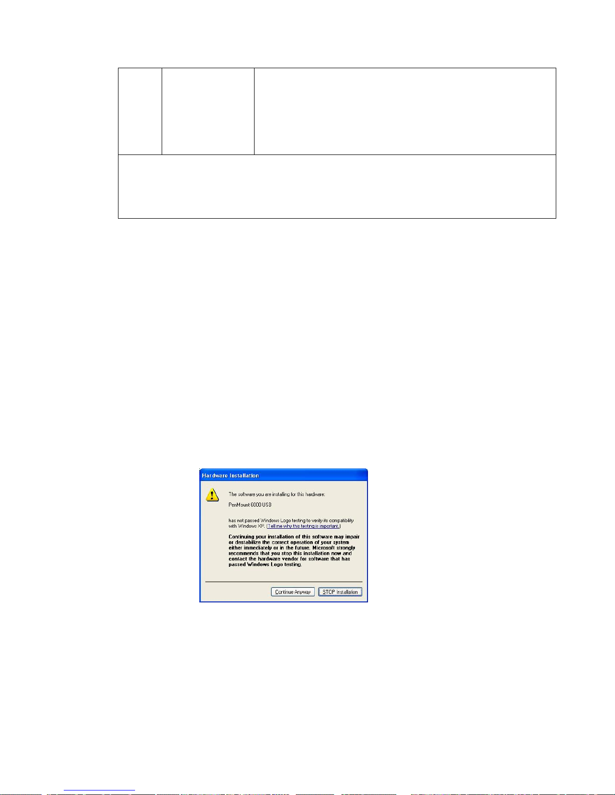
5. When the warning message screen appears, please click “Continue
Anyway” to continue.
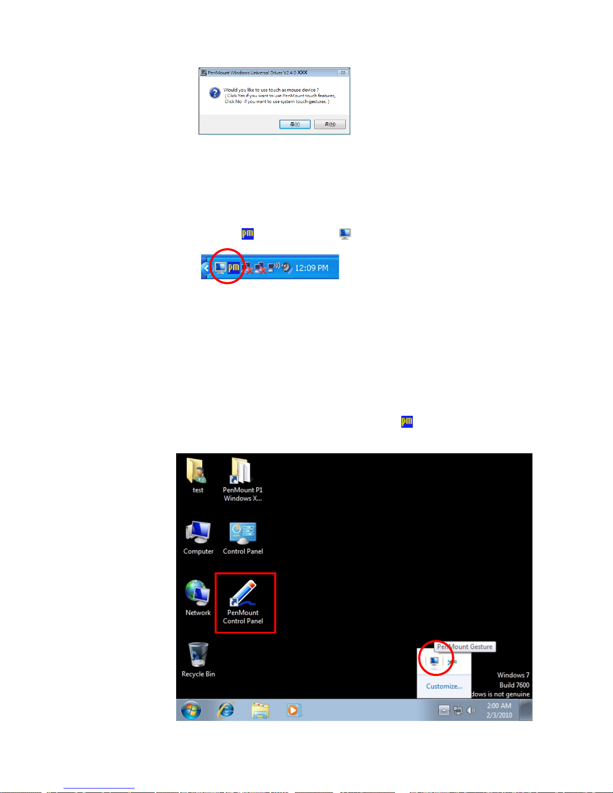
6. When the window below shows up, please select “yes” for installing
PenMount as mouse mode; select “no” for digitizer mode. If your
operating system doesn’t support Windows tablet input, digitizer device
can’t be used, therefore you have to select “yes” here, otherwise after the
installation the touch doesn’t work after re-booting.
Page 44
Install Drivers for 9000 Boards
38
7. A window notifying of installation completion appears. Click “Finish”.
NOTE: If you are installing the driver with Microsoft WHQL, you will see
the screen in step 6 directly instead of step 5.
8. Then restart operating system.
As soon as driver installation finishes, both the icons of PenMount
Monitor
and Gesture AP show up in the notification area.
3.6.2. Install PenMount Digitizer Driver in Windows XPT/VISTA/7/
WES7/2008/ 8
The default installation steps are same as XP. To select “no” in step 6,
PenMount will be installed as a digitizer device; If your operating system
doesn’t support Windows tablet input, digitizer device can’t be used, therefore
you have to select “yes” here, otherwise after the installation the touch doesn’t
work after re-booting.
After the installation,You will see the difference that a PenMount Control
Panel icon shows up on the desktop without the
icon in the notification
area. See the screenshot below:
Page 45
Install Drivers for 9000 Boards
39
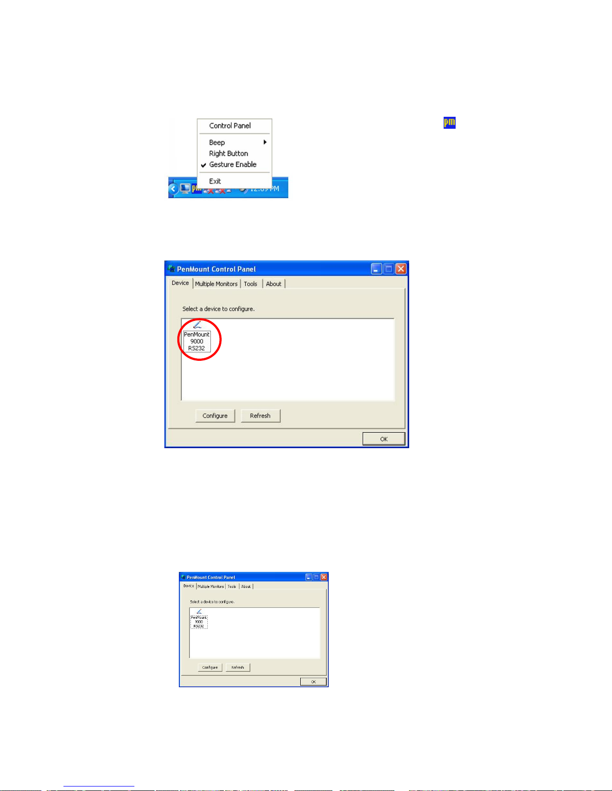
3.6.3. Configure Touch screen In PenMount mouse driver
Click PenMount Monitor icon
at the
notification area and select Control Panel from
the menu.
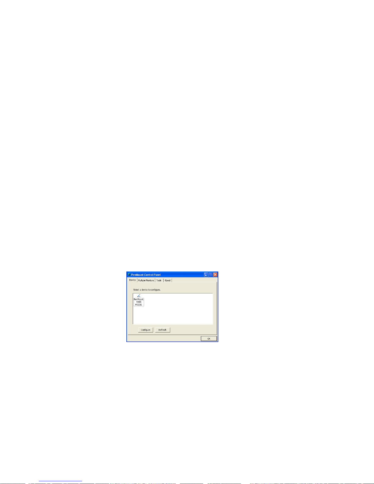
On PenMount Control Panel
you are able to see the device of PenMount
9000 RS-232 detected by your system under
Device
tab. Select a device and
click the
Configure
button.
3.6.3.1 PenMount Control Panel
The functions of PenMount Control Panel are:
Device
In this window, you can find out how many devices are detected in your
system.
Page 46
Install Drivers for 9000 Boards
40
Calibrate
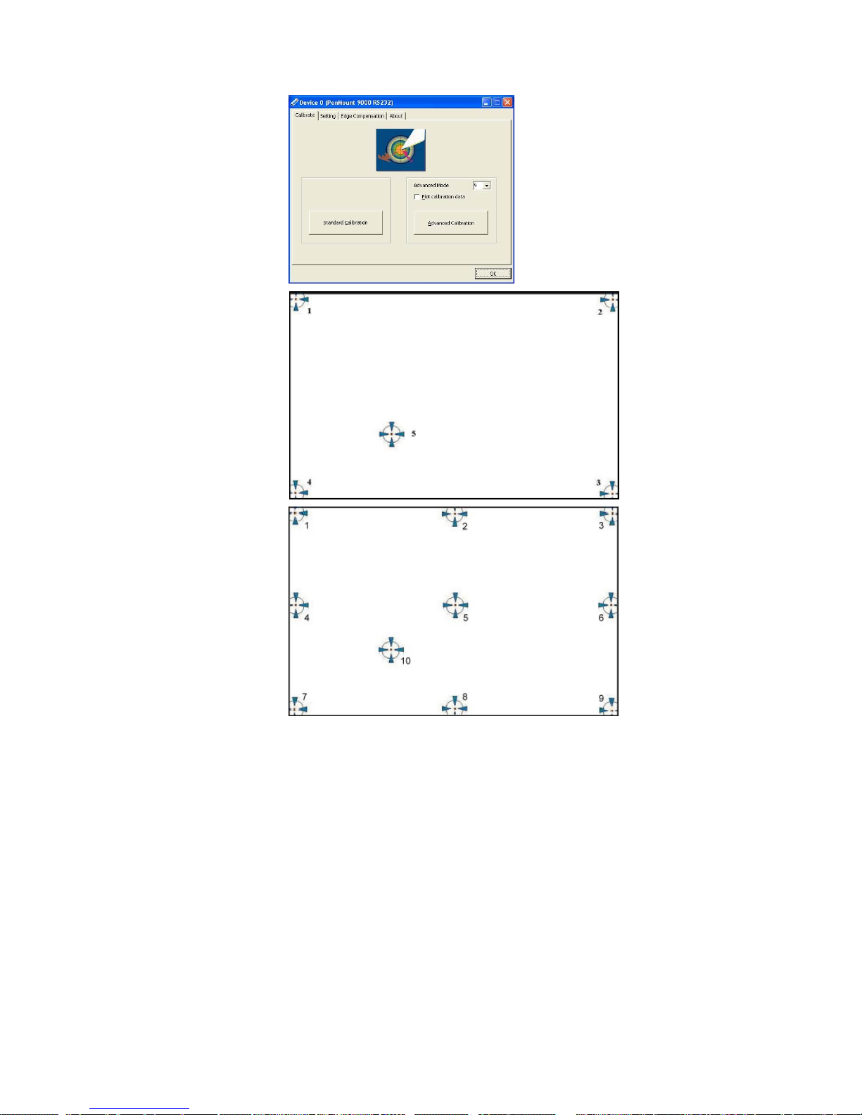
This function offers two ways to calibrate your touch screen. ‘Standard
Calibration’ adjusts most touch screens while ‘Advanced Calibration’
adjusts aging touch screens.
Standard
Calibration
Click this button and arrows appear pointing to red squares.
Use your finger or stylus to touch the red squares in
sequence. After the fifth red point calibration is complete. To
skip, press ‘ESC’.
Advanced
Calibration
Advanced Calibration uses 9, 16 or 25 points to effectively
calibrate touch panel linearity of aged touch screens. Click
this button and touch the red squares in sequence with a
stylus. To skip, press ‘ESC’.
Command
Calibration
Command call calibration function. Use command mode
call calibration function, this can uses 4, 9, 16 or 25
points to calibrate.
E.g. Please run ms-dos prompt or command prompt.
c:\Program Files\PenMount Universal Driver\DMCCtrl.exe
-calibration 4 (Standard Calibration)
DMCCtrl.exe - calibration ($)
4= Standard Calibration 4
9= Advanced Calibration 9
16= Advanced Calibration 16
25= Advanced Calibration 25
To calibrate your touch screen:
1. Please select a device then click “
Configure
”. You can double click the
device too.
2. Click “
Standard Calibration
” to start the standard calibration or
“
Advanced Calibration
” for Advanced Calibration.
Page 47
Install Drivers for 9000 Boards
41
NOTE : The older a touch screen is, the more calibration points of
the Advanced Mode it needs. For an optimal accuracy, we
suggest to use a stylus to make the advanced calibration.
Plot Calibration Data
Check this function to have touch panel
linearity comparison graph appear when you
finish Advanced Calibration. The black lines
reflect the ideal linearity assumed by
PenMount’s application program while the blue
lines show the approximate linearity calculated
by PenMount’s application program as the
result of user’s execution of Advance
Calibration.
Turn off EEPROM
storage
This function disables the write-in of calibration
data in
Controller. This function is enabled by default.
Page 48
Install Drivers for 9000 Boards
42
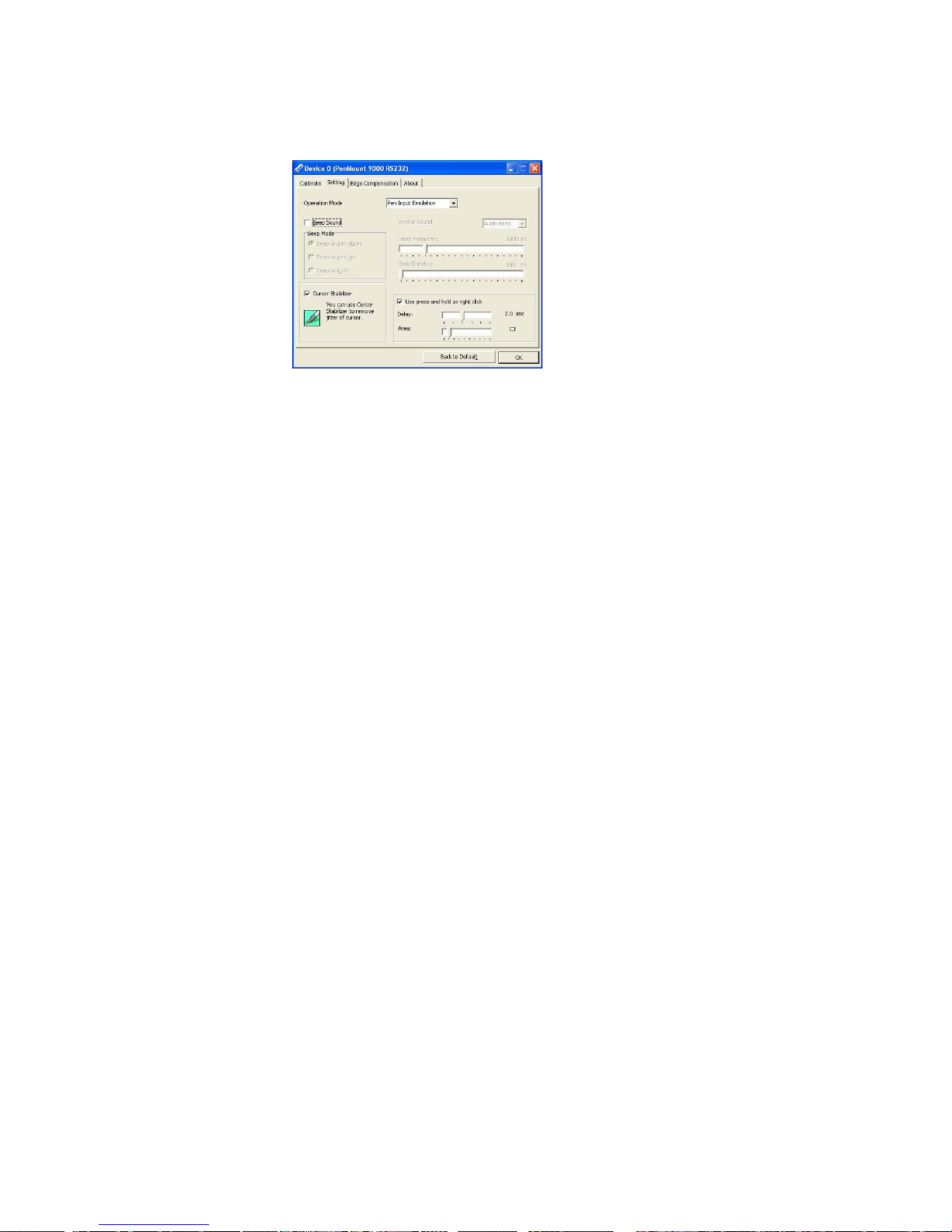
Setting
Operation
Mode
This mode enables and disables mouse’s ability of dragging
on-screen icons—useful for configuring POS terminals.
Pen Input
Emulation
Select this mode and mouse will emulate
Windows Vista pen input device operation, by
which no mouse event will be sent until the
touch is dragged out of range or released
from the screen.
Mouse
Emulation
Select this mode and mouse functions as
normal and allows dragging of icons.
Click on
Touch
Select this mode and mouse only provides a
click function, and dragging is disabled.
Click on
Release
Select this mode and mouse only provides a
click function when the touch is released.
Beep
Sound
Enable Beep Sound – turns beep function on and off.
Beep on Pen Down – beep occurs when pen comes
down.
Beep on Pen Up – beep occurs when pen is lifted
up.
Beep on both – beep occurs when comes down
and is lifted up.
Beep Frequency – modifies sound frequency.
Beep Duration – modifies sound duration.
Cursor Stabilizer
Enable the function support to prevent cursor
shake.
Use press and
hold as right click
You can set the time out and area for you need
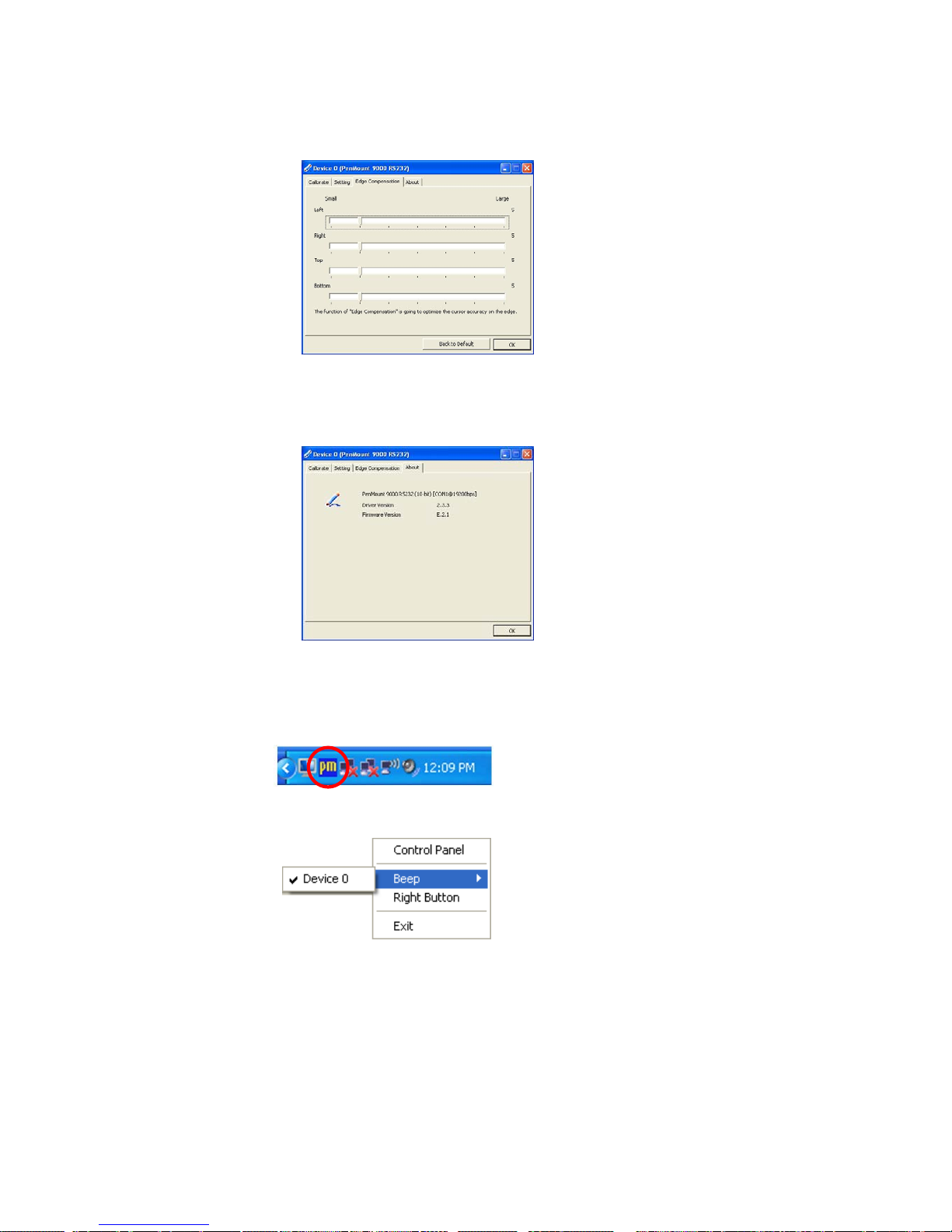
Edge Compensation
This page is the edge compensation settings for the advanced calibration.
Page 49
Install Drivers for 9000 Boards
43
You can adjust the settings from 0 to 30 for accommodating the difference
of each touch panel.
About
This panel displays information about the PenMount controller and driver
version
3.6.3.2 PenMount Monitor Menu Icon
PenMount Monitor icon (PM) appears in the notification area of Windows
system when you turn on PenMount Monitor in PenMount utility.
PenMount Monitor has the following functions:
Control Panel
Open PenMount Control Panel.
Beep
Setting Beep function for each device.
Right Button
When you select this function, a mouse icon
appears in the right-bottom of the screen. Click
this icon to switch between Right and Left Button
functions.
Page 50
Install Drivers for 9000 Boards
44
Exit
Exits the PenMount Monitor function.
3.6.3.3 PenMount Rotating Functions
PenMount Windows Universal Driver supports several display rotating
software packages and auto-detects rotate function (0°, 90°, 180°, 270°).
The display rotating software package supported in Windows 2000, XP 32bit,
Vista 32/64bit are:
1. Intel Display Driver Rotate Function.
2. ATI Display Driver Rotate Function.
3. nVidia Display Driver Rotate Function.
4. SMI Display Driver Rotate Function.
5. Portrait’s Pivot Screen Rotation Software.
Configure Rotate Function in Windows XP 64bit
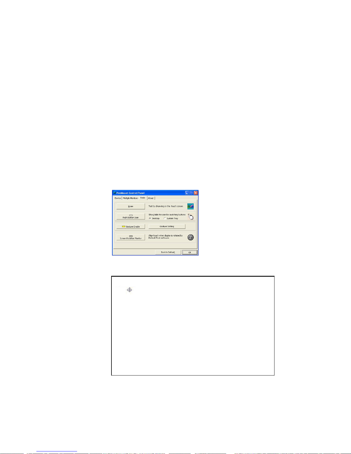
1. There is a “Screen Rotation Monitor” button that appears only in the
PenMount driver utilities for Windows XP 64bit system.
2. On “Screen Rotation Monitor”, you will see a screen like below:
3. Choose rotate function (0°, 90°, 180°, 270°) in the 3
rd
party software. The
calibration screen will appear automatically. Touch this point and rotation
is mapped.
Page 51
Install Drivers for 9000 Boards
45
NOTE: Rotate function will be disable if you use Monitor Mapping.
3.6.4. The Touch screen Configure of PenMount Digitizer Driver
To configure touch screen in PenMount Digitizer driver:
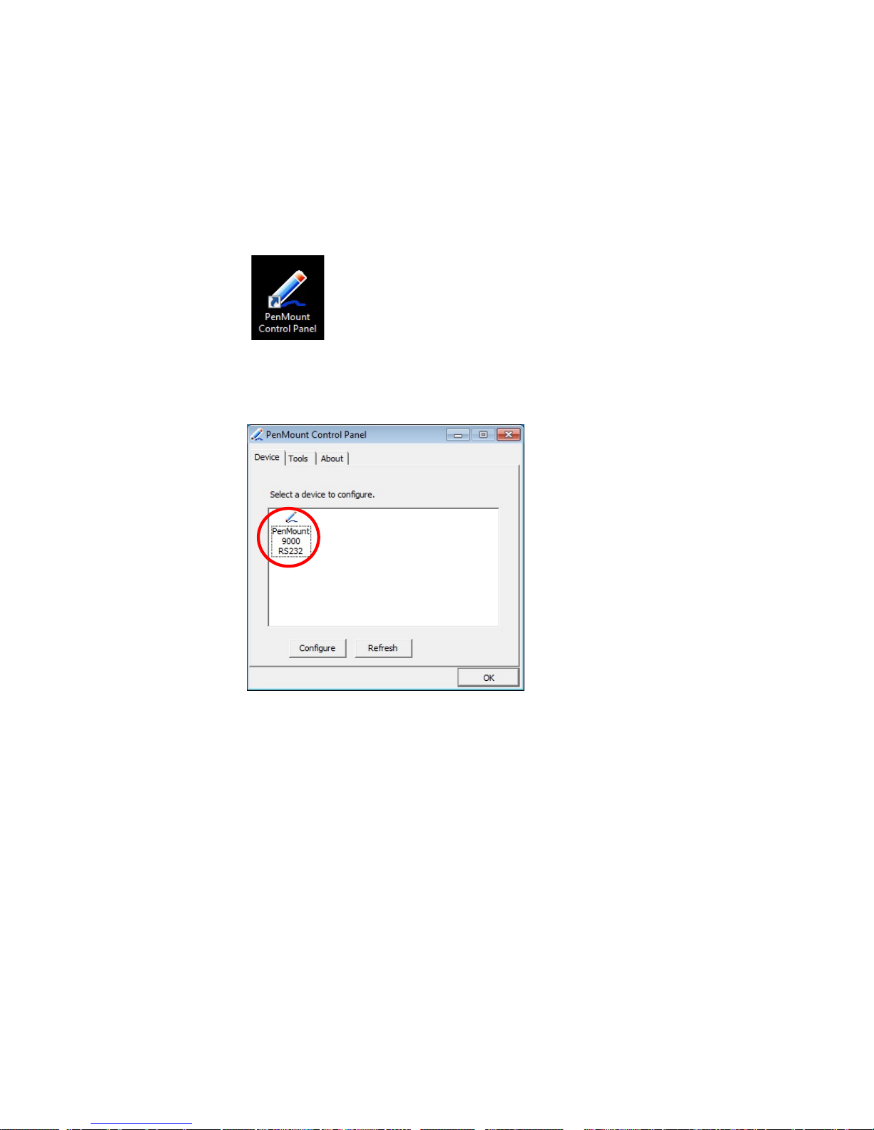
Double-click on the
PenMount Control Panel
icon on the Desktop.
On PenMount Control Panel
you are able to see the device of PenMount
9000 RS-232 detected by your system under
Device
tab. Select a device and
click the
Configure
button to configure it.
3.6.4.1. PenMount Control Panel
The functions under PenMount Control Panel are:
Device
In this tab, you can find out how many devices are detected on your
system. Select any device by clicking on its icon.
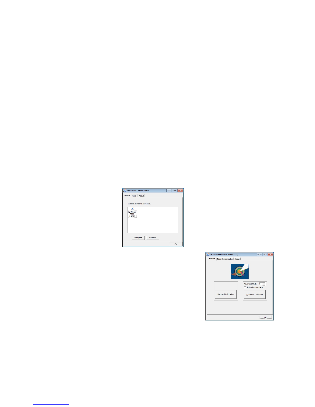
Calibrate
This function offers two ways to calibrate your touch screen. ‘Standard
Calibration’ adjusts most touch screens while ‘Advanced Calibration’
adjusts aging touch screens.
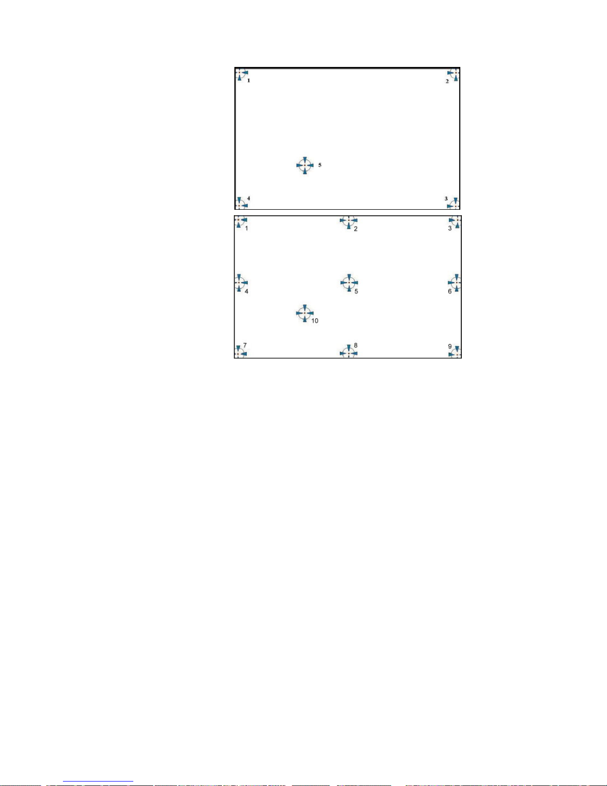
Standard
Calibration
Click this button and arrows appear pointing to red
squares. Use your finger or stylus to touch the red
squares in sequence. After the fifth red point the
calibration is complete. To skip, press ‘ESC’.
Advanced
Advanced Calibration uses 9, 16 or 25 points to
Page 52
Install Drivers for 9000 Boards
46
Calibration
calibrate touch panel linearity of aged touch screens
efficiently. Click this button and touch the red
squares sequencely with a stylus. To skip, press
‘ESC’.
Command
Calibration
Command call calibration function. Use
command mode call calibration function, this
can uses Standard, 4, 9, 16 or 25 points to
calibrate.
E.g. Please run ms-dos prompt or command prompt.
c:\Program Files\PenMount Universal
Driver\DMCCtrl.exe -calibration 0 (Standard
Calibration)
DMCCtrl.exe - calibration ($)
0= Standard Calibration
4=Advanced Calibration 4
9=Advanced Calibration 9
16=Advanced Calibration 16
25=Advanced Calibration 25
To calibrate your touch screen:
1. Please select a device then click “
Configure
”. You can double
click the device too.
2. Click “
Standard Calibration
” to
start the standard calibration.
Page 53
Install Drivers for 9000 Boards
47
NOTE : The older a touch screen is, the more calibration points of
the Advanced Mode it needs. For an optimal accuracy, we
suggest to use a stylus to make the advanced calibration.
Plot Calibration Data
Check this function to have touch panel
linearity comparison graph appear when you
finish Advanced Calibration. The black lines
reflect the ideal linearity assumed by
PenMount’s application program while the blue
lines show the approximate linearity calculated
by PenMount’s application program as the
result of user’s execution of Advance
Calibration.
Turn off EEPROM
storage
This function disables the write-in calibration
data function in Controller. This function is
enabled by default.
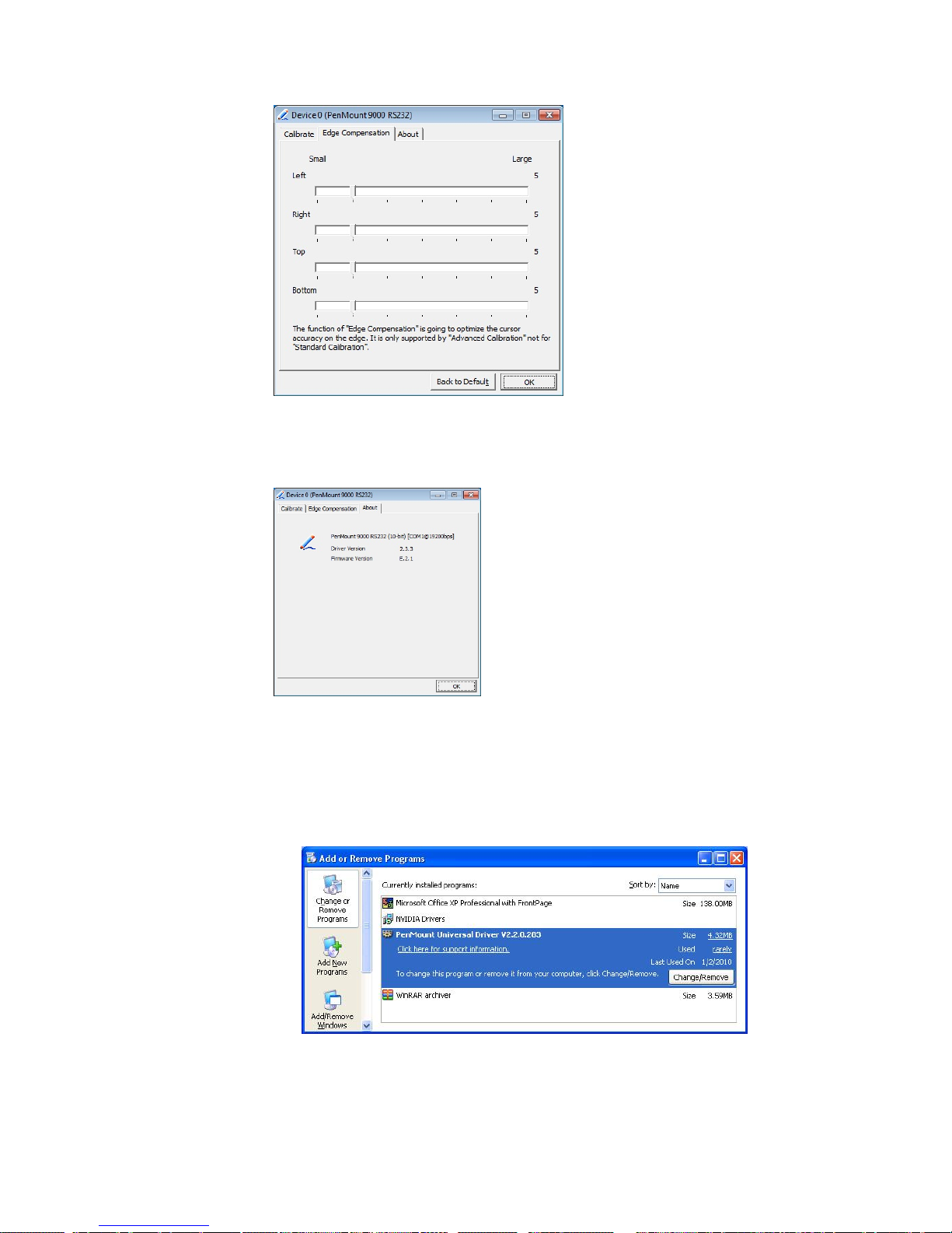
Edge Compensation
This page is the edge compensation settings for the advanced calibration. You
can adjust the settings from 0 to 30 for accommodating the difference of each
touch panel.
Page 54
Install Drivers for 9000 Boards
48
About
This panel displays information about the PenMount controller and driver
version
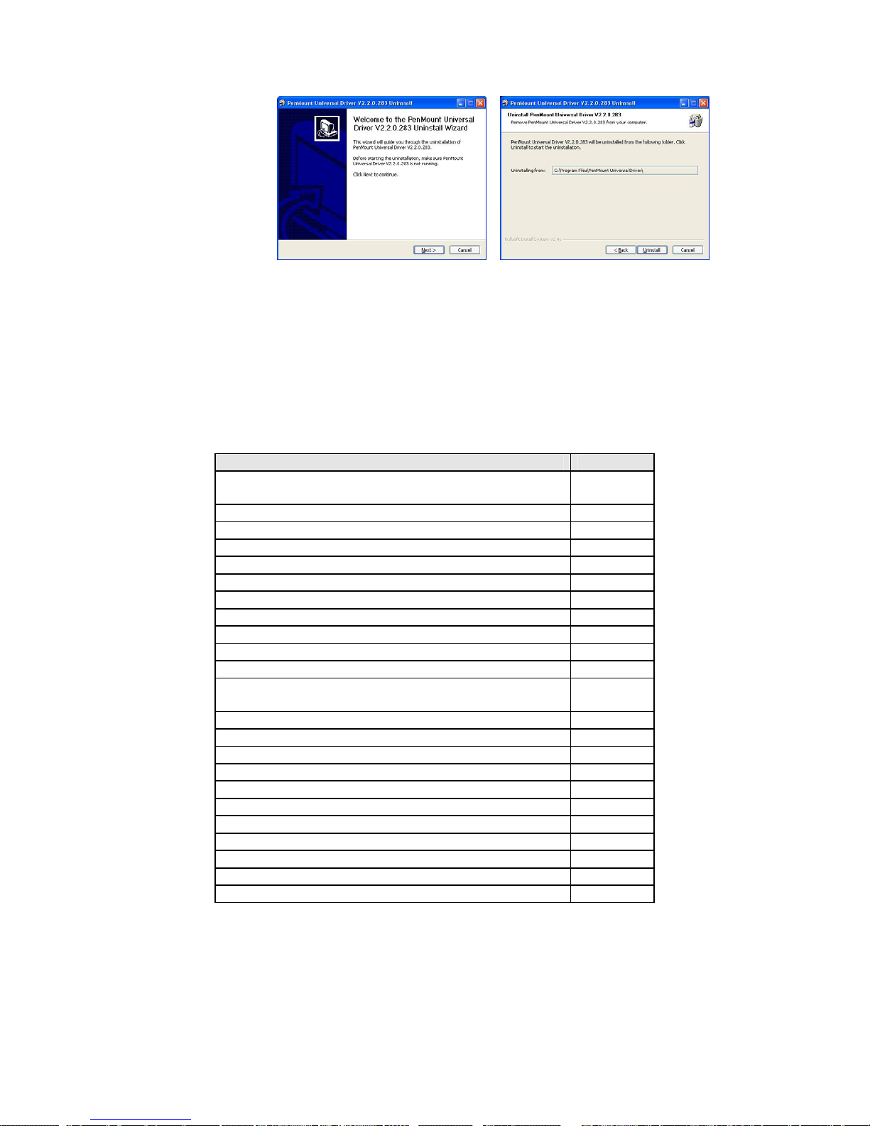
3.6.5. Uninstall PenMount Windows Universal Driver
1. Go to Control Panel. Click “Add/Remove program”. Select ”PenMount
Universal Driver”. Click “Change/Remove” button..
2. Select ‘Uninstall’ to remove PenMount Windows Universal Driver.
Page 55
Install Drivers for 9000 Boards
49
3.7. Install PenMount Linux X Window RS-232 Driver
Before installing PenMount Linux X Window RS-232 Driver, you must have Linux X
Window installed and running on your computer. You must also have PenMount Serial
Interface either 9026BH or 9036CH control boards installed.
PenMount Linux X Window RS-232 Driver supports the following operating systems:
RS232
Ubuntu 6.06/ 6.10/ 7.04/ 7.10/ 8.04/ 8.10/ 9.04/ 9.10/
10.04/ 10.10/ 11.04/ 11.10/12.04 32_64bit
●
Debian 4.0/ 5.0 32_64bit/ 6.0 ●
Debian 3.1
Fedora 4/5/6/7/89/10/11/12/13 /14/15/16/17 32_64bit ●
Fedora Core4_64bit
Fedora Core3 ●
Fedora Core2 ●
Slackware12.0/12.1 ●
Slackware10.0
Red Hat 9.0 ●
Red Hat 7.3/8.0 ●
OpenSuse 10.1/ 10.2/ 10.3/ 11/ 11.1/ 11.2/ 11.3/ 11.4/
12.1 32_64bit
●
Suse 10.0 ●
Suse 9.2/9.3
Suse 8.0/9.0/9.1
Cent OS 5.2/ 5.3/ 5.4/ 5.5/ 6.0/ 6.2 32_64bit ●
Linux XFree86 4.x.x
Linux XFree86 3.3.6
Linux For GPM ●
QNX 6.4.1/ 6.5 ●
QNX 6.3.2
QNX 6.2 ●
Android ●
3.7.1. Install PenMount Linux X Window RS-232 Driver
Please see the readme file included in the driver folder.
Page 56

Install Drivers for 9000 Boards
50
3.7.2. Calibration Utilities
Please see the readme file included in the driver folder.
3.8. Install PenMount WinCE Driver
Before installing PenMount WinCE Driver, you must have WinCE system installed and
running on your device. You must also have PenMount Serial Interface either 9026BH or
9036CH control boards installed.
NOTE: Make sure you can move the WinCE cursor with a serial mouse attached to the
target COM port (e.g. COM2) before connecting the 9000 control board.
3.8.1. Install PenMount WinCE Driver
Please see the readme file included in the driver folder.
Page 57
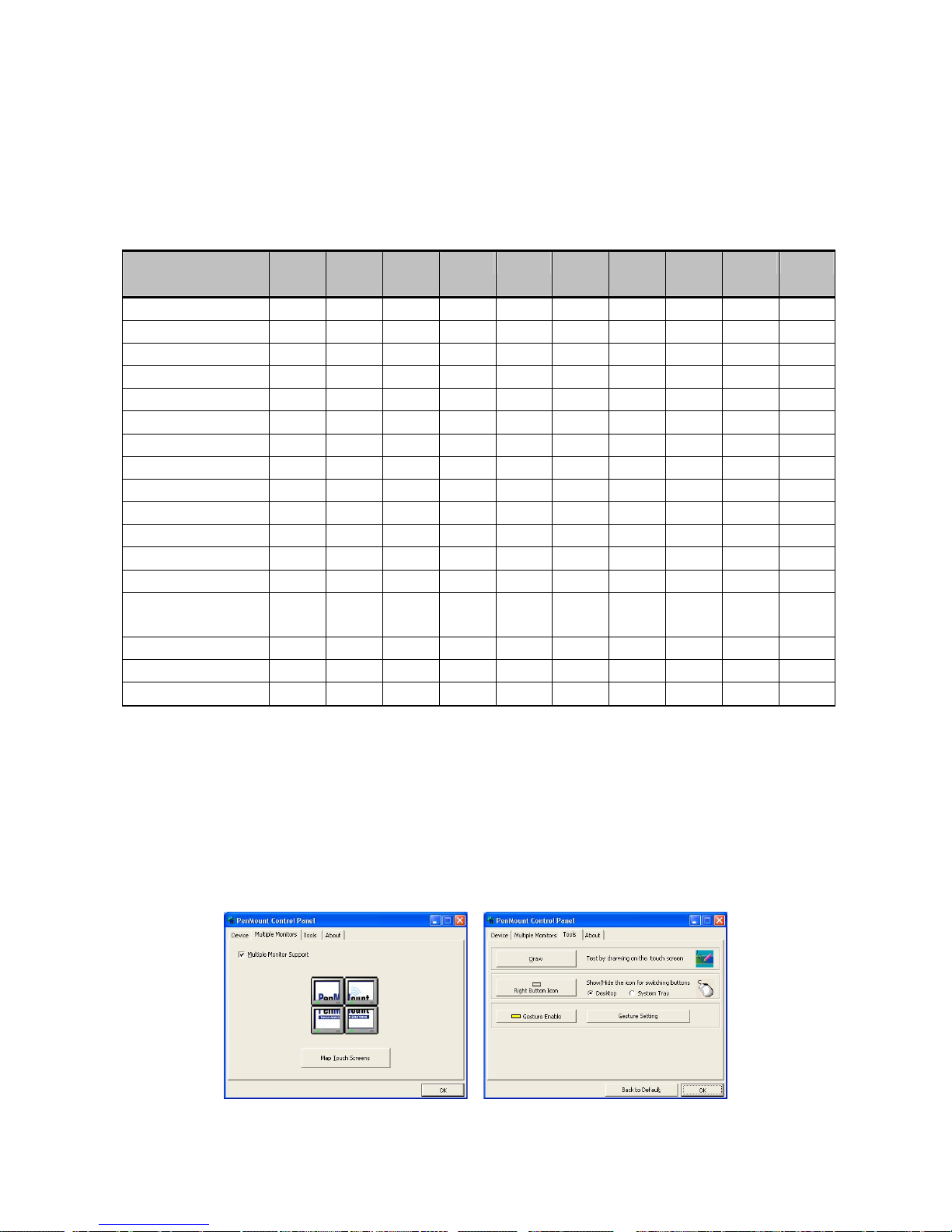
51
Chapter 4. Driver Software Functions
This chapter will guide you to the special software functions that configure and adjust PenMount
control boards and touch screen hardware. Please note that not all of the functions are available for
every driver. See the following table for drivers’ software functions and their availability for specific
interface and systems.
Software Function DOS Win 3.1 95 98/ME NT 2000/XP
/2003/
VISTA/7/8 CE Linux QNX
Standard Calibration ● ● ● ● ● ● ● ● ● ●
Advanced Calibration ● ● ● ● ● ●
Multiple Monitors ● ●
Multi Device ● ●
Rotation ● ● ● ● ●
Operation Mode ● ● ●
Drawing mode ● ● ● ● ● ● ● ●
Beep Sound ● ● ● ● ● ● ● ● ●
Beep sound adjustable ● ● ●
Wake up function ● ● ●
Showing linearity ● ● ●
Right button ● ● ● ● ● ● ● ● ●
Hide cursor ● ● ● ●
Double click area and
speed adjustable
● ● ● ●
About ● ● ● ● ● ●
Edge Compenstation ● ●
Refresh ● ●
Remark:
With PenMount Windows Universal V2.2.0.283 and the versions later, since the touch screen is installed
as a digitizer device in Windows Vista/7/8 automatically, the functions which are built in Windows Vista / 7/
8, such as rotation, multi-monitors, flicks, and context menu function (which launches a context menu by
long-pressing on touch screen rather than clicking the right-mouse button or pressing the application key
on the keyboard will be supported.
The following content in this chapter deals mainly with PenMount Windows Universal Driver (for
2000/XP/2003/VISTA/7/8). When you click PenMount icon in the notification area and select
“Control Panel” from the menu, “PenMount Control Panel” with the four tags “Device”,
“Multiple-Monitors”, “Tools”, “About” will appear as the screenshot below:
Page 58

Driver Software Functions
52
The buttons on “Tools”tab have the following functions:
Draw
Tests or demonstrates the PenMount touch screen
operation.
Right Button Icon
Enable right button function. The icon can be shown on
Desktop or in the notification area.
Gesture Enable
Enable/configure Gesture AP to support PenMount
gestures recognition.
Screen Rotation Monitor
The function supports nVidia, Intel, SMI or ATI and
software such as Portrait Pivot Pro rotation automatic
detection.
4.1. Standard Calibration
Standard Calibration allows touch screen match the display so that the point you where
you touch can be traced accurately on the screen. Standard Calibration only requires
four points for calibration and one point for confirmation. Under normal circumstance,
Standard Calibration is all you need to perform an accurate calibration.
4.2. Advanced Calibration
Advanced Calibration: improve the accuracy of calibration by using the more
complicated engineering calculations. Use this function only if you have tried the
Standard Calibration and there is still a discrepancy in the way the touch screen maps
to the display. You can choose 9, 16 or 25 points to calibrate, though we suggest that you
first try 9 points, if it is still not tracking well then try 16 or 25 points. The more points you
use for calibration, the greater the accuracy. Errors in calibration may occur due to
viewing angle, or individual skill, and there may be little difference in using 16 or 25 points.
A stylus is recommended for the most accurate results.
4.3. Multiple Monitors
PenMount mouse drivers for Windows 2000/XP/XPE/2003/VISTA/72008/WES7/8
support Multiple Monitors. Multiple Monitors supports from two to six touch screen
displays for one system. Each monitor requires its own PenMount touch screen control
board, either installed inside the display or in a central unit. PenMount control boards
must be connected to the computer COM ports via the RS-232 interface. Driver
installation procedures are the same as for a single monitor. Multiple Monitors supports
the following modes:
Windows Extend Monitor Function
Matrox DualHead Multi-Screen Function
nVidia nView Function
NOTE: Multiple Monitors function is for use with multiple displays only. Do not use
this function if you have only one touch screen display. Please note once you
turn on this function Rotating function is disabled.
Page 59
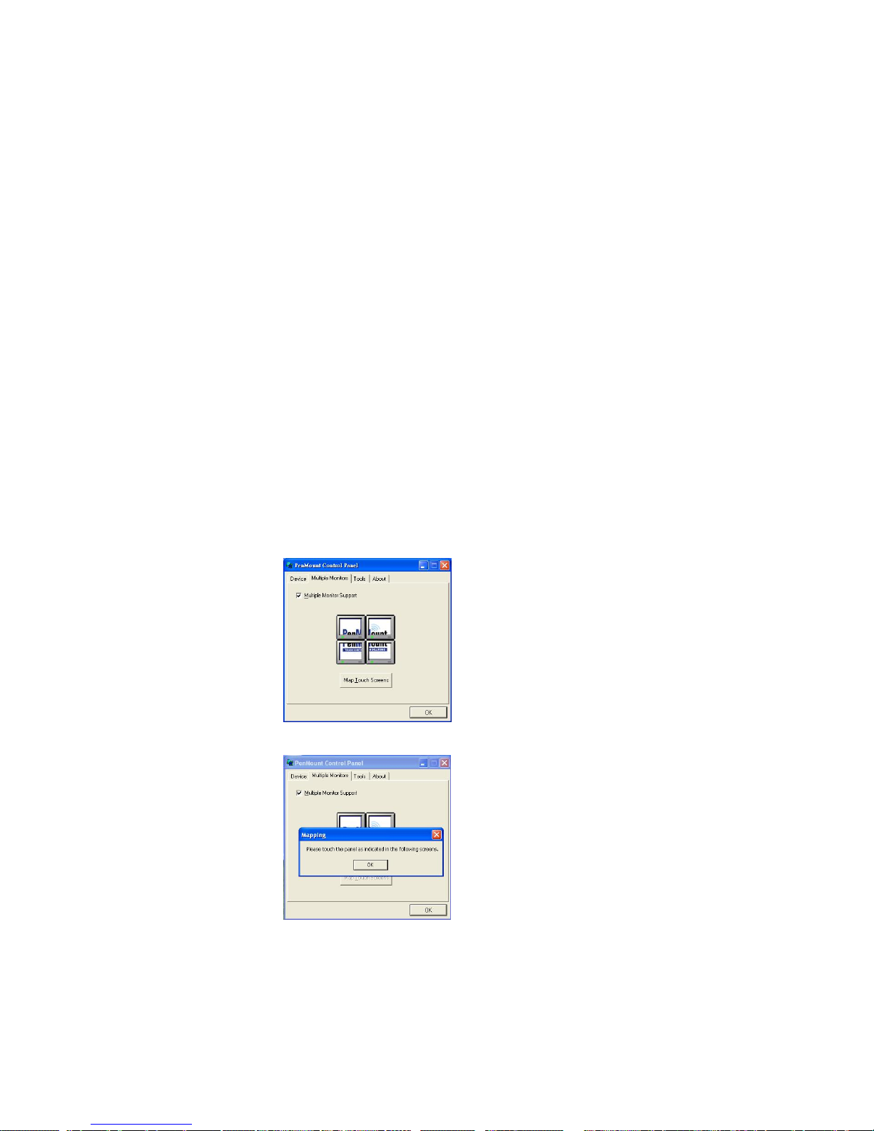
Driver Software Functions
53
4.3.1. Requirements
Before using Multiple Monitors function you need the following:
- A display card that supports multiple monitors such as the Matrox, nVidia,
ATI, etc.
- (Two or more display cards supported by Windows are also ok.)
- Two or more touch screens
- Two or more Serial Ports
- Two or more PenMount 9000 control boards such as the 9036CH or
9026BH.
- PenMount Windows Universal Driver (for 2000/XP/2003/VISTA/7/8).
Before using Multiple Monitors, you must have two or more monitors that are
in extension mode. For display cards that support multiple monitors, we
suggest you consider Matrox, nVidia, or ATI cards and inquire about operation
and usability issues.
Note: Before you can use multiple monitors, you need to map each monitor.
Enable Multiple Monitors
Enable the multiple display function as follows:
1. In PenMount Control Panel, under Multiple Monitors tag, check the
“Multiple Monitor Support” box. Then click “Map Touch screens” to
assign touch controllers to displays.
2. When the mapping screen message appears, click “OK”.
3. Touch each screen as it displays “Please touch this monitor. Press ‘S’
to skip”. Follow this sequence and touch each screen to map the touch
screens.
Page 60
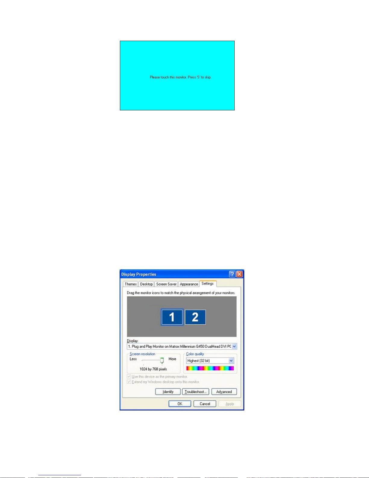
Driver Software Functions
54
4. After the setting procedure is finished, maybe you need to calibrate for
each panel and controller.
NOTE: If you use a single VGA output for multiple monitors, please do
not use Multiple Monitors function. Just follow the regular
procedure for calibration on each of your desktop monitors.
Rotate function will be disable if you use Multiple Monitors
function.
If you change the resolution of display or screen address, you
have to redo Map Touch screens so the system understands
where the displays are.
If you have multiple monitors but only one touch screen, press ‘S’
to skip mapping step.
4.3.2. An Example for 2 Touch Monitors
1. Please make sure 2 touch monitors are plugged in and detected.
Page 61
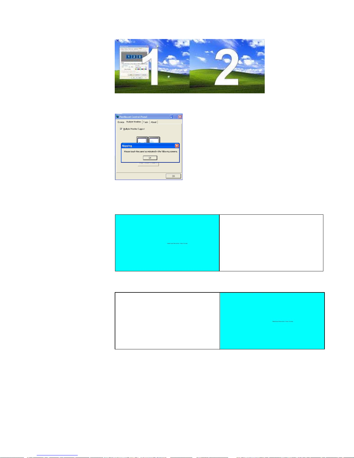
Driver Software Functions
55
2. In PenMount Control Panel, under Multiple Monitors tag, click “Map
Touch screens” then click “OK”.
3. Then follow the screen instructions to match the controller with the touch
screen.
3-1. Click “S” to skip if you don’t use the touch function on that screen.
3-2. When it jumps to screen 2, touch it. If you don’t use touch function
on screen 2, press “S” to skip it.
4. Before calibrating the screens, finish the procedure of “Map touch
screens”.
5. Carry out Calibrate for each device in sequence.
Page 62
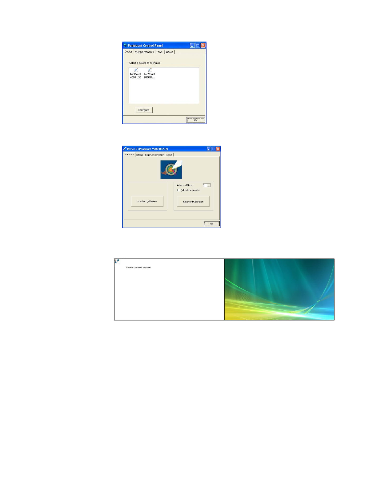
Driver Software Functions
56
6. Press each device & start with Standard Calibrate, for instance, device
0.
7. After you press device 0, one of the screens will show calibration map.
8. Calibrate the other screens with the same way.
4.4. Multiple Devices
Multiple Devices: allow using two or more monitors to display the same image. Software
that supports this function includes the PenMount Windows Universal Driver (for 2000/
XP/XPE/2003/VISTA/7/2008/WES7/8) only. This driver for PenMount can support up to
six control boards.
Page 63
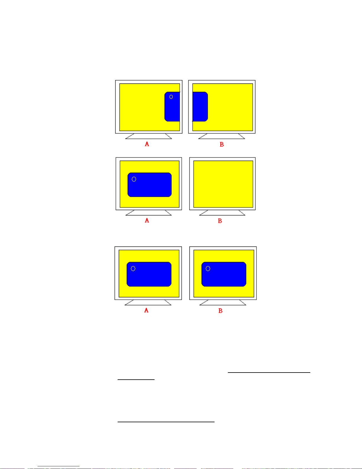
Driver Software Functions
57
4.4.1. Compare Functions
The differences of the functions between Multiple Monitors and Multiple
Devices are illustrated below.
or
Multiple Monitors function shown above extends the screen into 2 or more
monitors.
Multiple Devices function displays the same image on two or more monitors.
4.4.2. Requirements
To u se Multiple Devices with PenMount Control Boards, you need to do the
following:
1. Configure your computer hardware. See Chapter 2: Install PenMount
9000 Control Boards on page 2.
2. Attach each PenMount Control Board to a different computer’s serial or
USB port.
3. Install the appropriate PenMount software driver in each computer— see
Chapter 3. Install Drivers for 9000 Boards on page 8.
Page 64
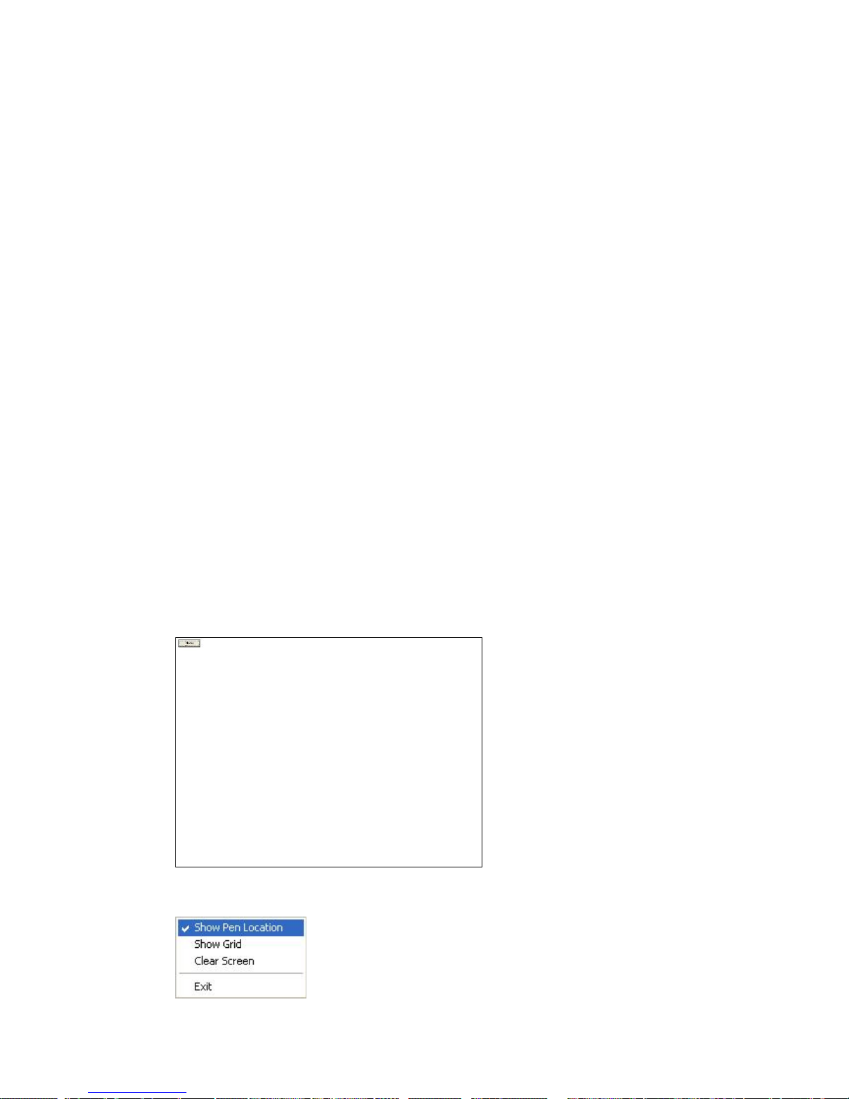
Driver Software Functions
58
4. Use each driver’s Calibrate function to calibrate each computer’s touch
screen.
5. You must calibrate each touch screen before configuration is complete.
4.5. Rotation
There are currently a number of software packages on the market that support rotating
monitors 0°, 90°, 180°, and 270°. However, you will not be able to use a touch screen
unless it is matched to the appropriate rotation. Our rotation configuration function allows
you to match the touch screen easily when you rotate your monitor.
If you use a rotating monitor, you will need a display card such as from nVidia, Intel, SMI
or ATI and software such as Portrait Pivot Pro. For software operation and features,
please refer to your software manual.
Configuring the rotation function is easy. Select this option and a ‘point’ appears for you
to touch. Once the point is touched, the software driver understands which degree you
plan to rotate your display. The rotation function supports 90, 180 and 270-degree
rotation.
4.6. Draw
To test or demonstrate the PenMount touch screen operation. The display shows touch
location. Click Draw to start. Touch the screen with your finger or a stylus and the
drawing screen registers touch activity such left, right, up, down, pen up, and pen
down.
Touch the screen with your finger or a stylus and the drawing screen registers touch
activity such left, right, up, down, pen up, and pen down.
Click Menu button for more functions.
Page 65
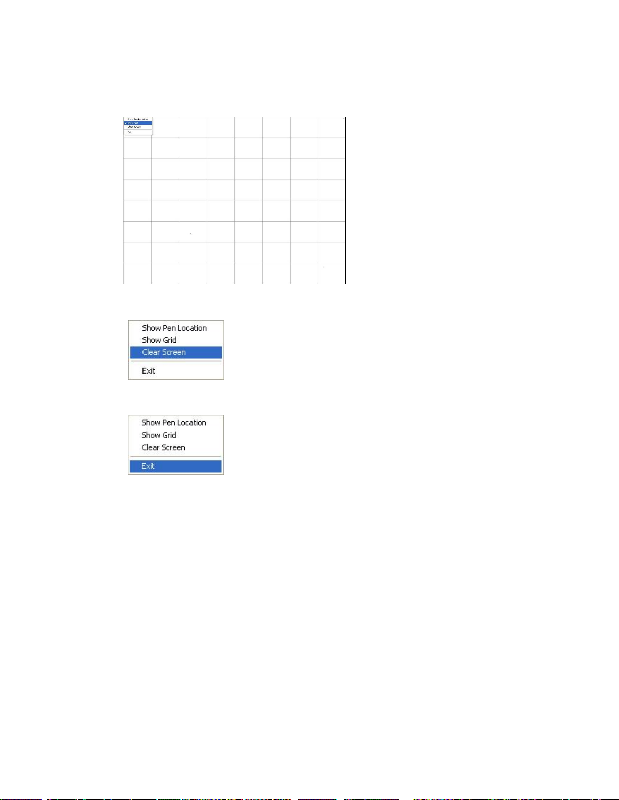
Driver Software Functions
59
Show Pen Location is to show the locations where pen comes down and lifted up on the
monitor.
Show Grid is to show grid on the entire monitor. This is for linearity test.
Select Clear Screen to clear drawing.
Select Exit to quit draw function
4.7. Mouse Operation Mode
Mouse Operation Mode enables and disables mouse’s ability of dragging onscreen
icons, which is applicable to the configuration of POS terminals.
Pen Input Emulation –
Select this mode and mouse will emulate Windows Vista pen
input device operation, by which no mouse event will be sent
until the touch is dragged out of range or released from the
screen.
Mouse Emulation – Select this mode and mouse functions as normal and allows
dragging of icons.
Click on Touch – Select this mode and mouse only provides a click function,
disable dragging function.
Click on Release – Select this mode and mouse only provides a click function
when the touch is released.
Page 66

Driver Software Functions
60
4.8. Beep Sound
All of PenMount’s drivers support the beep sound function; however, some PC systems
may only offer a fixed buzzer sound.
4.9. Beep Sound Adjustable
Software drivers for Windows systems let the user adjust the frequency and length of the
beep sound. The drivers let the user adjust the desired touch screen sound, as well as
turn the sound off.
4.10. Wake Up Function
Wake Up function lets the user touch the screen and wake the system up from ‘suspend’
mode.
4.11. Plot Calibration Data
Plot Calibration Data function displays the touch screen linearity map, which is available
if the PenMount driver provides an Advance Calibration function. Touch panel’s linearity
decreases with panel’s age. This non-linearity is apparent when the touched point on the
touch screen is not the same as the point on the display. Plot Calibration Data function
shows the linearity status of the touch screen. This is only a support function for the user.
The exact linearity of a touch screen requires a linearity test machine.
4.12. Right Button
Right Button function simulates the right button function of a mouse. Click the right
button and the user can only touch the screen once and the driver changes the touch
definition to the left button.
4.13. Hide Cursor
Hide Cursor function keeps the cursor arrow and other cursor symbols from appearing
when using the touch screen. The cursor appears when user turns this function off.
4.14. Cursor Offset
Cursor Offset function lets the user adjust the position of the touch point to a desired
location away from the real touch point.
4.15. Double Click Area and Speed
Double Click Area and Speed function lets the user adjust the double click area and
speed to their personal preference.
4.16. About
This option shows the exact version of the drivers and controller firmware. Updated
drivers are available for downloading on the PenMount website at
http://www.penmount.com/ .
Page 67
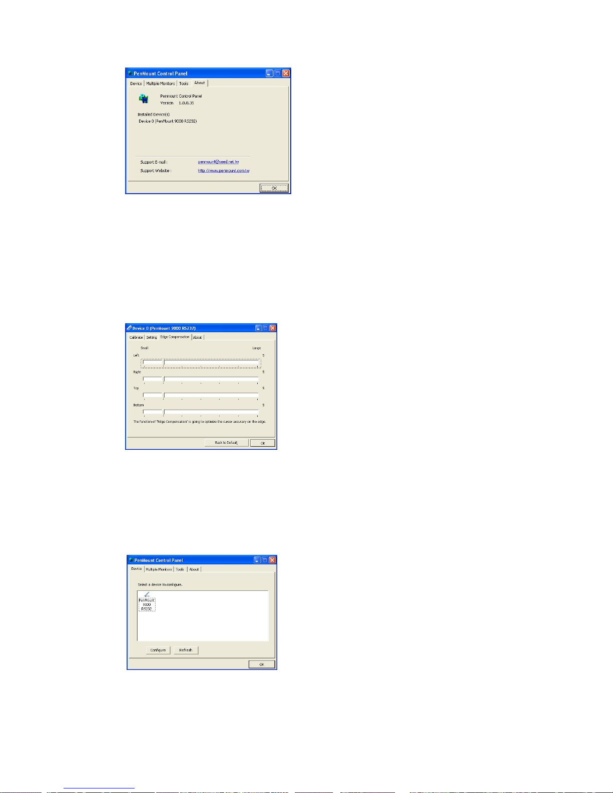
Driver Software Functions
61
4.17. Edge Compensation
In PenMount Control Panel, when any of the detected PenMount device is selected and
the Configure button is clicked, you will be able to see the Edge Compensation tag,
which is for Advanced Calibration. You can adjust the settings from 0 to 30 for
accommodating the difference of each touch panel. (Note: Edge Compensation is only
supported by PenMount Windows Universal Driver (for Windows 2000/ XP/ XPE/ 2003/
VISTA/ 7/ 2008/ WES7/ 8)
4.18. Refresh
If you install PenMount driver package after( includes) 2.1.0.187, you can click the
Refresh button in PenMount Control Panel to detect the newly attached PenMount
devices. (Note: PenMount Windows Universal Driver only supports Refresh (for
Windows 2000/ XP/ XPE/ 2003/ VISTA/ 7/ 2008/ WES7/ 8).
Page 68

62
Chapter 5. PenMount Gesture AP for Windows
2000/XP/VISTA/7/8
This chapter will guide you to the PenMount Gesture AP that is applicable in Windows
2000/XP/Vista/7/8.
5.1. Invoke PenMount Gesture AP
1. Make sure you have installed PenMount touch screen control boards (whether 6000
or 9000 series).
2. Make sure you have installed PenMount Universal Driver V2.1.0.XXX or later
versions to your system.
3. To run PenMount Gesture AP
In the notification, right-click on the PenMount icon and select Gesture Enable from
the menu. A PenMount Gesture AP icon will show up in the notification area. See the
illustration below. PenMount Gesture AP is running.
or
In PenMount Control Panel, select Tools tab and press Gesture Enable button.
PenMount Gesture AP icon shows up in the notification area. PenMount Gesture
AP is running.
PenMount Gesture AP
Enabled Disabled
Page 69
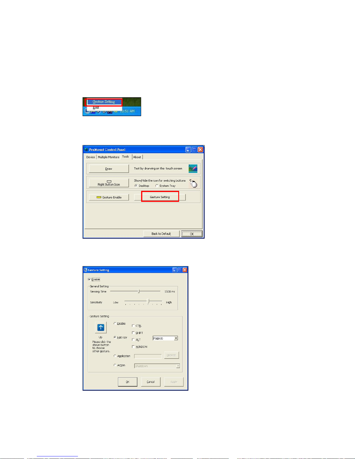
PenMount Gesture AP
63
5.2. Configure PenMount Gesture AP
To configure PenMount Gesture AP
1. Right-click on the PenMount Gesture AP icon in the notification area, select Gesture
Setting from the menu that appears. See the illustration below.
or
Select Tools tab and press Gesture Setting button in PenMount Control Panel.
2. [Gesture Setting] window displays.
Page 70
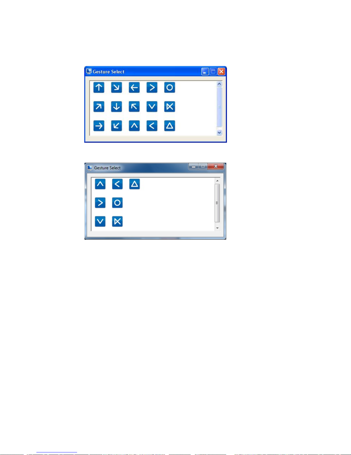
PenMount Gesture AP
64
3. 15 PenMount Gestures are provided in total.
For Windows XP
For Windows Vista / 7/ 8
4. In the [Gesture Setting] window, you can proceed to configure PenMount Gesture
AP:
Page 71
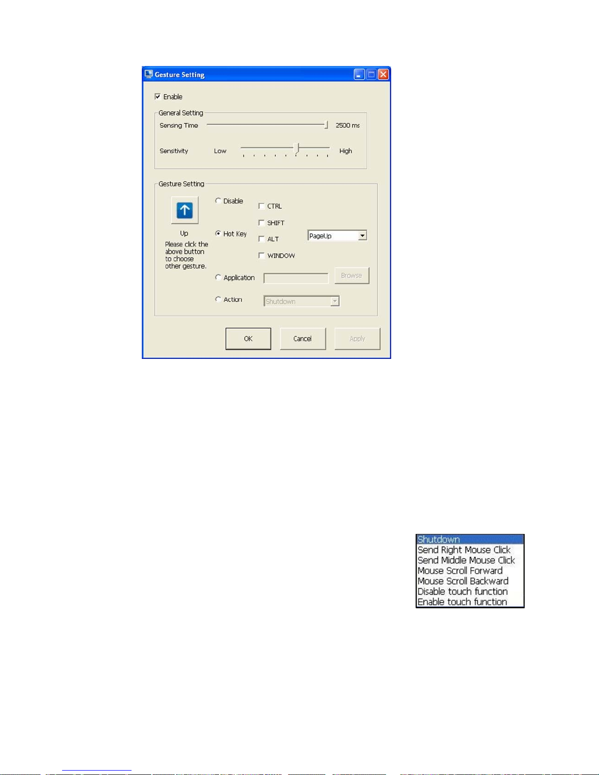
PenMount Gesture AP
65
a. Enable/disable
Check Box.
Select/deselect the
box to enable/disable
PenMount Gestures.
b. General Setting Box
b-1. Sensing Time -
Move the slider to
adjust PenMount
Gestures Sensing
Time between 200
ms (0.2 sec) and
2500 (2.5 sec). The
shorter the sensing
time is configured,
the faster the gesture
has to be done.
b-2. Sensitivity – Move
the slider to adjust
how sensitive you
want your finger
stroke on the
touchsceen to be
sensed.
c. Gesture Settings Group Box. This group box allows you to individually
configure each gesture.
d. Gesture Select Button. Press this button to select the specific gesture you are
going to configure. When the gesture icon turns to blue, it is enabled. When it is
gray, it is disabled. See the following for details.
d-1. Disable Button. When this button is selected, the gesture is disabled.
d-2. Hot-key Configure Button. Configure the hot-keystrokes for specific gesture.
The hot-key can include up to 5 keystrokes. When that gesture is sensed, the
configured keystrokes will be reported.
d-3. Application Invoke Button. Configure to invoke a specific application with
particular gesture. So that when the gesture is sensed, the specific application
will run.
d-4. Action Configure Button. Configure to make use of
PenMount Gesture AP’s built-in shortcuts. So that
when a particular gesture is sensed, a specific action
will be taken. PenMount Gesture AP have the
following shortcuts built in:
Note: For Disable touch function, after touch function is disabled, the
mouse-pointer won’t move following your finger sliding on the touch screen
and your finger tapping won’t trigger any action, however, gestures will still
be sensed.
(Note: If you select
Disable touch function
, the curser will not react
to finger movement on the touch screen and the tapping will not
trigger any program action. However, the gesture recognition is still
functioning.)
b
d-4
d-3
d-2
d-1
c
d
a
b-1
b-2
Page 72
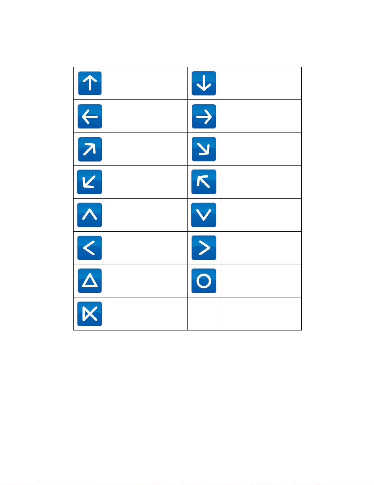
PenMount Gesture AP
66
5.3. PenMount Gestures’ Default Values in Windows XP
Page Up
Page Down
Backward
(Left Arrow)
Forward
(Right Arrow)
Copy
(Ctrl + C)
Paste
(Ctrl + V)
Undo
(Ctrl + Z)
Delete
Zoom in
([Pad] +)
Zoom out
([Pad] -)
Rotate Counter Clockwise
(Ctrl + L)
Rotate Clockwise
(Ctrl + K)
Open On-Screen
Keyboard
(Execute OSK.EXE)
Save Document
(Ctrl + S)
Close Program
(Alt + F4)
 Loading...