

Page 1
PENKO Engineering B.V.
Your Partner for Fully Engineered Soluons
Manual:
SGM800 Digizer
Scan for manual
For more information visit
www.penko.com - technical support - literature library
Page 2

SGM800 Digizer
IMPORTANT SAFETY INFORMATION
READ THIS PAGE FIRST!
Penko Engineering manufactures and tests
its products to meet all applicable naonal
and internaonal standards. It is vital that
this instrument is correctly installed, used,
and maintained to ensure it connues to
operate to its opmum specicaon.
The following instrucons must be adhered
to and incorporated into your safety
program when installing, using, and
maintaining Penko products. Failure to
follow the recommended instrucons can
aect the system’s safety and may increase
the risk of serious personal injury, property
damage, damage to this instrument and
may invalidate the product’s warranty.
• Read the instrucons fully prior to
installing, operang, or servicing the
product. If this Instrucon Manual is not the
correct manual for the Penko product you
are using, call 0031(0)318-525630 for a
replacement copy. Keep this Instrucon
Manual in a safe place for future reference.
• If you do not fully understand these
instrucons, contact your Penko
representave for claricaon.
• Pay careful aenon to all warnings,
cauons, and instrucons marked on and
supplied with the product.
• Inform and educate your personnel about
the correct installaon, operaon, and
maintenance procedures for this product.
• Install your equipment as specied in the
installaon instrucons of the appropriate
Instrucon Manual and as per applicable
local and naonal codes. Connect all
products to the proper electrical sources.
• To ensure correct performance, use qualied personnel to install, operate, update,
program, and maintain the product.
• When replacement parts are required,
ensure that qualied technicians use repla-
cement parts specied by Penko. Unauthorized components and procedures can aect
the product's performance and may aect
the connued safe operaon of your
processes. The use of non-specied ‘lookalike’ substuon parts may result in the
risk of re, electrical hazards, or improper
operaon.
• Ensure that all equipment doors are closed
and protecve covers are in place, except
when maintenance is being performed by
qualied persons, to prevent electrical
shock and personal injury.
2
Page 3

SGM800 Digizer
WARNING
ELECTRICAL SHOCK HAZARD
Installing cable connecons and servicing this instrument require access to shock hazard
level voltages which can cause death or serious injury.
Disconnect separate or external power sources to relay contacts before commencing any
maintenance.
The electrical installaon must be carried out in accordance with CE direcons and/or any
other applicable naonal or local codes.
Unused cable conduit entries must be securely sealed by non-ammable blanking plates or
blind grommets to ensure complete enclosure integrity in compliance with personal safety
and environmental protecon requirements.
To ensure safety and correct performance this instrument must be connected to a
properly grounded, three-wire power source.
Proper relay use and conguraon is the responsibility of the user.
Do not operate this instrument without the front cover being secured. Refer any
installaon, operaon or servicing issues to qualied personnel.
WWW.PENKO.COM
Penko is an ETC Company
e-mail: [email protected]
3
Page 4

SGM800 Digizer
TABLE OF CONTENT
Chapter Page
1. Loadcell power connection 6
1.1 SGM800 basic digitizer
1.2 SGM810 digitizer analog
1.3 SGM820 digitizer Ethernet
1.4 SGM830 digitizer CAN
1.5 SGM840 digitizer Profibus
1.6 SGM850 digitizer Serial
2.Indication of display 12
3. Explanation of front keys 13
4. First use of Indicator 14
4.1 Configuration menu structure 14
4.2 Display indication at startup 15
4.3 Weigher Setting 16
4.4 Calibration 18
4.5 First use by using PI Mach II software 22
5. Main Menu 30
5.1 Setpoints (not for SGM810)
5.2 TAC (Traceable Acces Code) 31
5.2 CAL (Calibration counter) 32
6. Configuration Menu 33
6.1 Setpoint function settings (not for SGM810)
6.2 Setpoint action settings (not for SGM810)
6.3 Analog output settings 37
6.4 Local bus communication settings (RS485) 41
6.5 Ethernet settings (SGM820 only) 42
6.6 Can bus port settings (SGM830 only) 48
6.7 Profibus settings (SGM840 only) 51
6.8 RS232 port settings (SGM850 only) 53
6.9 RS422 port settings (SGM850 only) 57
6.10 Indicator settings 61
6.11 Multi range/interval settings 68
6.12 Filter settings 71
6.13 Digital filter settings 75
6.14 Pre-calibration settings 77
6.15 Calibration settings 80
6
7
8
9
10
11
30
34
35
4
Page 5

SGM800 Digitizer
TABLE OF CONTENT
Chapter Page
6.16 Theoretic calibration 85
6.17 Geographic calibration 90
6.18 Date and time configuration (SGM850 only) 93
6.19 Recall 94
6.17 Firmware update 95
7. Firmware update 96
8. Event Log 98
9. Alibi Memory 99
9.1 SGM800 Indicator Alibi Memory 100
9.2 SGM800 Controller CHK Alibi Memory 101
9.3 SGM800 Controller MFL Alibi Memory 102
10. Error codes 103
10.1 Weigher error codes
11. ASCII
11.1 ASCII protocol format
11.2 ASCII protocol commands
12. Profibus protocol description
13. Standard factory settings
Appendix I 111
104
104
104
105
107
108
5
Page 6
SGM800 Digizer
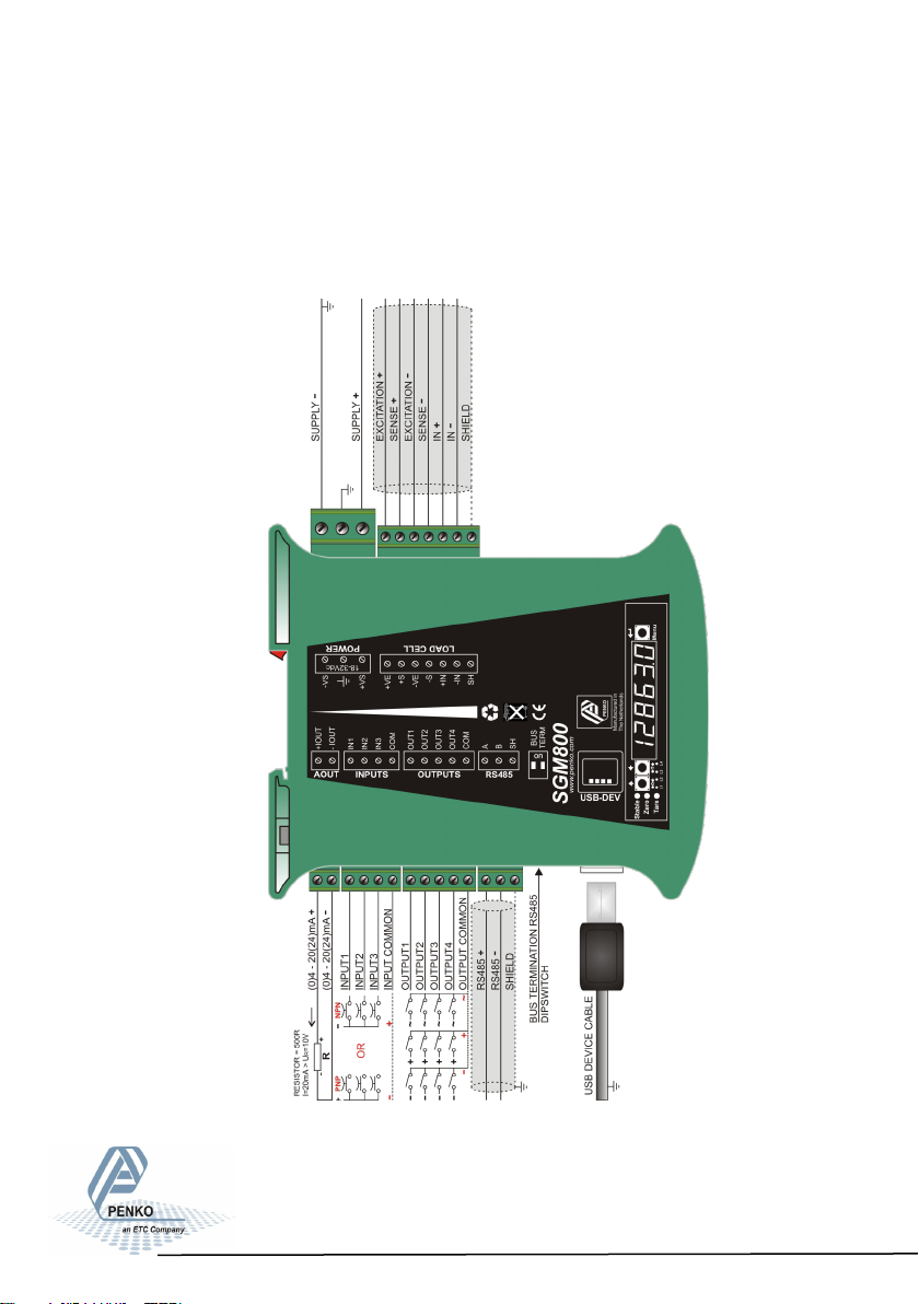
1. Load cell / power connection
1.1 SGM800 basic digitizer
DC POWER SUPPLY
18-32Vdc
6-Wire load cell
connection Vexc=5Vdc
- 32 Vdc, 0.2A@24Vdc.
This product is intended to be supplied by a Class 2 or
Limited Power Source, rate 18
Analoge output (option) Counter
’t work.
Outputs
25V/0.5A
iputs ,=1kHz
@VDC with
50% duty
cycle
AC/DC
Local bus
When the SGM800 is powered by USB
(not 24Vdc) the loadcell interface and
the analog output don
To PC
Config
software
6
Page 7
SGM800 Digizer
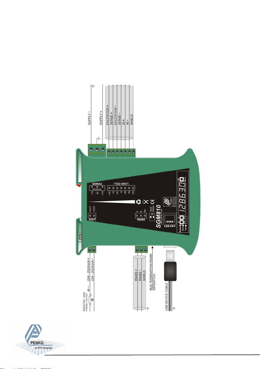
1. Load cell / power connecon
1.2 SGM810 digitizer analog
- 32 Vdc, 0.2A@24Vdc.
DC POWER SUPPLY
18-32Vdc
6-Wire load cell
connection Vexc=5Vdc
This product is intended to be supplied by a Class 2 or
Limited Power Source, rate 18
Analoge output (option)
’t work.
Local bus
When the SGM800 is powered by USB
(not 24Vdc) the loadcell interface and
the analog output don
To PC
Config
software
7
Page 8
SGM800 Digizer
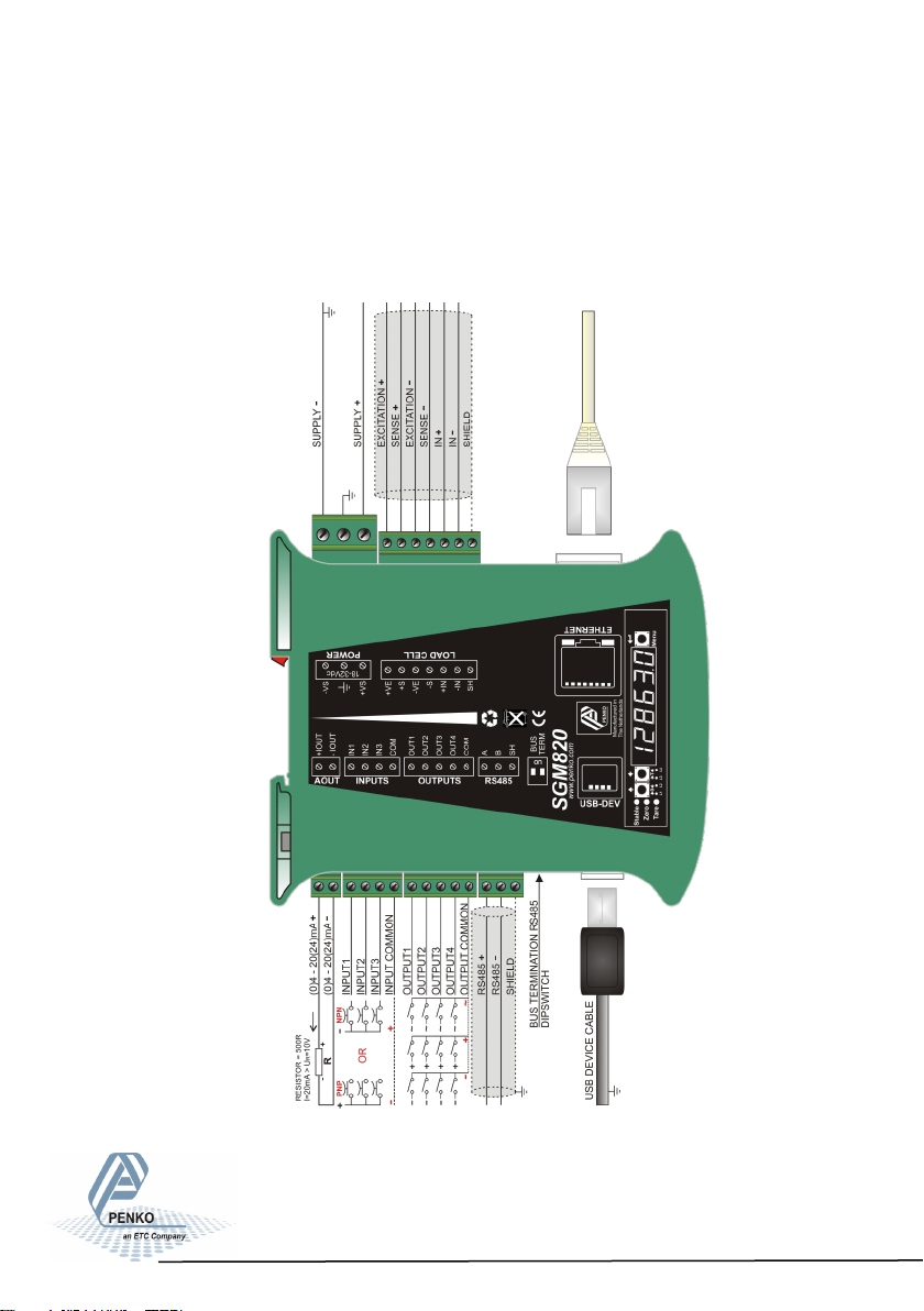
1. Load cell / power connecon
1.3 SGM820 digitizer ethernet
- 32 Vdc, 0.2A@24Vdc.
DC POWER SUPPLY
18-32Vdc
6-Wire load cell
connection Vexc=5Vdc
This product is intended to be supplied by a Class 2 or
Limited Power Source, rate 18
Analoge output (option)
’t work.
ounter
iputs ,=1kHz
@VDC with
50% duty
Outputs
cycle
Local bus
25V/0.5A
AC/DC
When the SGM800 is powered by USB
(not 24Vdc) the loadcell interface and
the analog output don
To PC
Config
software
8
Page 9
SGM800 Digizer
1. Load cell / power connecon
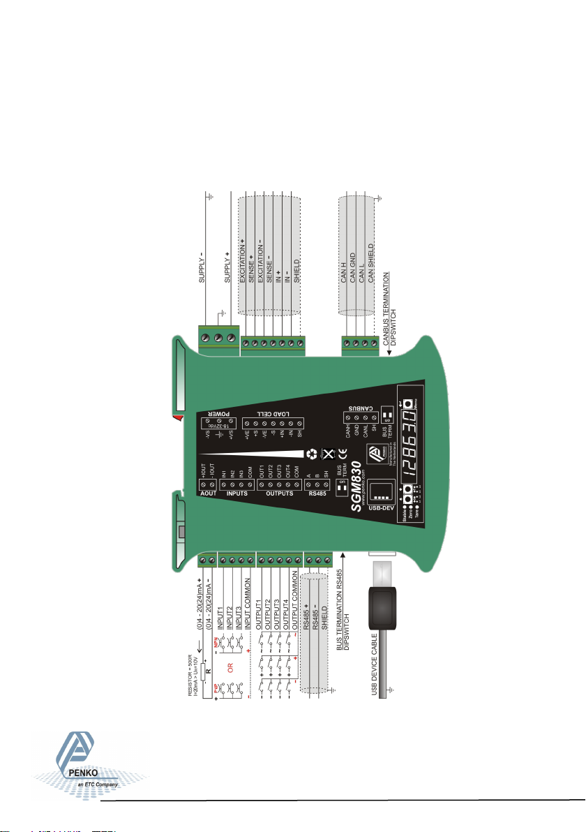
1.4 SGM830 digitizer CAN
- 32 Vdc, 0.2A@24Vdc.
DC POWER SUPPLY
18-32Vdc
6-Wire load cell
connection Vexc=5Vdc
Remote
canbus
This product is intended to be supplied by a Class 2 or
Limited Power Source, rate 18
Analoge output (option)
’t work.
Inputs
Input 1=5khz
18-28Vdc
Outputs 25V/0.5A
Local bus
AC/DC
When the SGM800 is powered by USB
(not 24Vdc) the loadcell interface, the
analog output and CAN bus don
To PC
Config
software
9
Page 10
SGM800 Digizer
1. Load cell / power connecon
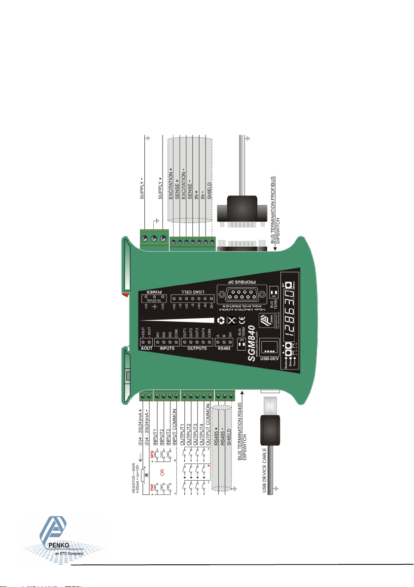
1.5 SGM840 digitizer Profibus
- 32 Vdc, 0.2A@24Vdc.
DC POWER SUPPLY
18-32Vdc
6-Wire load cell
connection Vexc=5Vdc
Profibus DP
This product is intended to be supplied by a Class 2 or
Limited Power Source, rate 18
Analoge output (option)
’t work.
Inputs
Input 1=5khz
18-28Vdc
Outputs 25V/0.5A
Local bus
AC/DC
When the SGM800 is powered by USB
(not 24Vdc) the loadcell interface, the
analog output and Probus don
To PC
Config
software
10
Page 11
SGM800 Digizer
1. Load cell / power connecon
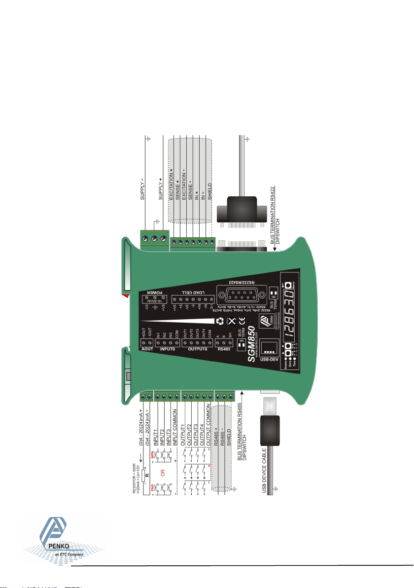
1.6 SGM850 digitizer Serial
DC POWER SUPPLY
- 32 Vdc, 0.2A@24Vdc.
18-32Vdc
6-Wire load cell
connection Vexc=5Vdc
RS232/RS422
This product is intended to be supplied by a Class 2 or
Limited Power Source, rate 18
Analoge output (option)
Inputs
Input 1=5khz
18-28Vdc
Outputs 25V/0.5A
Local bus
AC/DC
When the SGM800 is powered by USB
(not 24Vdc) the loadcell interface, the
analog output and Serial communicaon
don’t work.
To PC
Config
software
11
Page 12
SGM800 Digizer
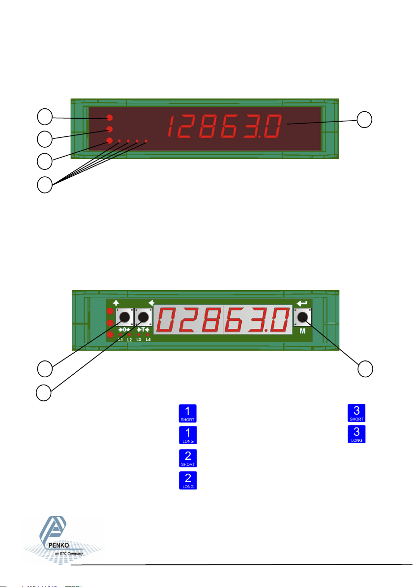
2. Indicaon of Display
With cover closed
1
2
3
4
1. Weigher stable
2. Zero active
3. Tare active
4. Output active 1-4
5. Weigher value
5
With cover opened
1
2
3
1. key 1 press <2sec.=
key 1 press >2sec.=
2. key 2 press <2sec.=
key 2 press >2sec.=
Functions of these keys will be described on the next page.
3. key 2 press <2sec.=
key 2 press >2sec.=
12
Page 13
SGM800 Digizer
3. Explanaon of front keys
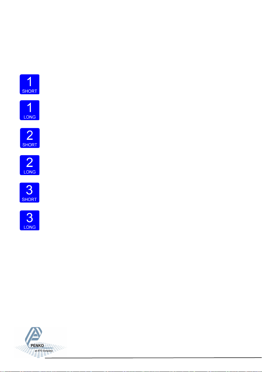
All keys have different functions depending if you are in weighing or
menu mode.
Pressing key 1 “short”.
In Weighing mode: create a new zero level.
In Menu mode: increase value by 1 or move up in menu.
Pressing key 1 “long”.
In Weighing mode: reset zero level to the original zero level.
In Menu mode: decrease value by 1 or move down in menu.
Pressing key 2 “short”.
In Weighing mode: set/ reset tare and reset preset tare.
In Menu mode: go into sub-menu or move cursor 1 position to the left.
Pressing key 2 “long”.
In Weighing mode: set preset tare.
In Menu mode: move cursor 1 position to the right.
Pressing key 3 “short”.
In Weighing mode: enter menu.
In Menu mode: escape move back in menu without saving changes.
Pressing key 3 “long”.
In Weighing mode: enter configuration menu.
In Menu mode: Confirm made changes.
Menu will jump back one level every 30 seconds of inactivity.
13
Page 14

SGM800 Digizer
4. First use of indicator
4.1 First use of indicator -Configuration menu structure-
- - - Fun setpoint function settings (not for SGM810 or controller)
- - - ACn setpoint action settings (not for SGM810 or controller)
- - - dAC Analog output settings
- - - 485 Local bus communication settings (RS485)
- - - Eth Ethernet settings (SGM820 only)
- - - CAn Can bus port settings (SGM830 only)
- - - - Pb Profibus settings (SGM840 only)
- - - 232 RS232 port settings (SGM850 only)
- - - 422 RS422 port settings (SGM850 only)
- - - Ind Indicator settings
- - - rng Multi range/interval settings
- - - FIL Filter settings
- - - dSF Digital filter settings
- - - PCL Pre-calibration settings
- - - CAL Calibration settings
- - - tCL Theoretic calibration
- - - gCL Geographic calibration
- - - CLo Date and time configuration
- - - rcL Recall
- - - SoF Firmware update
14
Page 15
SGM800 Digizer
4. First use of indicator
4.2 Display indication at startup
The start
Turn the indicator on by connecting it to the power supply.
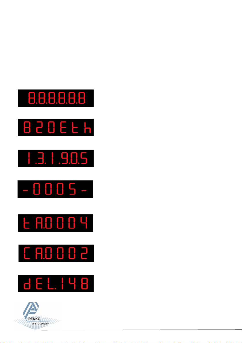
A series of display will appear:
Dislay test. Al l LED will turn o n to confirm that
the device display is functioning correctly.
Model Name. This shows the model name of
the device (in this case a SGM820 Ethernet).
Software version. This is the software version
installed in the device.
Software update counter. Th e number of times
that the software of the device is updated.
TAC code. The Traceable Acces s Code is the cou nter that keeps track ho w
many times
indicator setting are changed.
CAL Code. The Calibration co de is t he
counter that keeps track how many times the
calibration setting are changed.
Delay time. The delay time is warming up.
This is needed for certification. The counter will
count back from 180 to 0.
15
Page 16
SGM800 Digizer
4. First use of indicator
4.3 First use of indicator -Weigher settings-
Set up the correct indicator setting (step size and decimal point position).
Turn the indicator on by connecting it to the power supply.
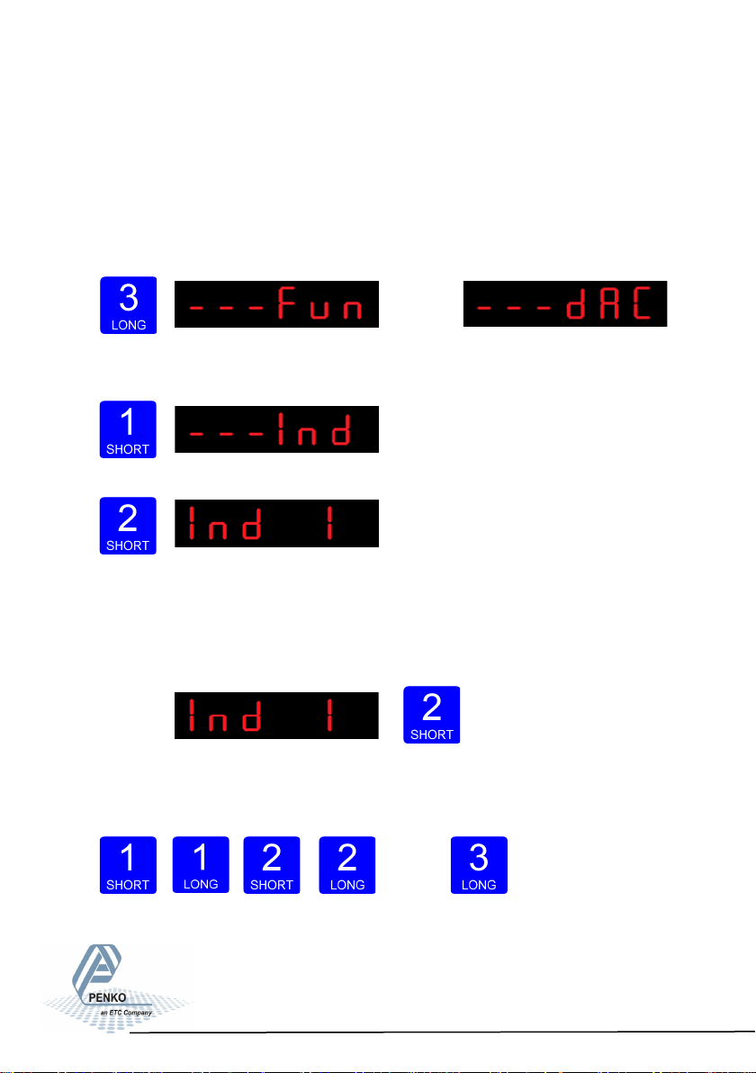
Press key 3 for >2
sec. to get in to
Con-
figuration Menu.
(In SGM810 or
controller)
Go to the Indicator parameters pressing key
1 <2 sec.
Go into the Indicator parameters pressing key 2.
Use Ind 1 to set the maximum net weight
value. Set maximum load to prevent
overload by the user. The indicator will not show any weight above the
filled in value. Range: 0 – full display.
To change the value, press key 2
<2 sec.
Use key 1 and 2 to change the value. Key 1 is for changing the number
(1-9), key 2 is for changing the position of the cursor. Confirm by pressing
16
Page 17
SGM800 Digizer
First use of indicator -connue-
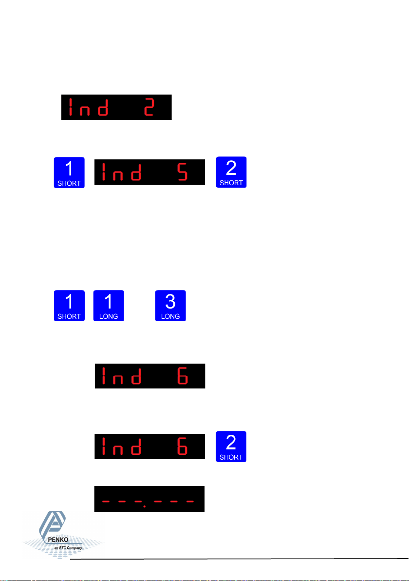
When the maximum net weight value is set succesfully, the following screen is
visible:
Dis- play step size
Press key 1 <2 sec. untill you see Ind 5 and press key 2 <2 sec.
Use Ind 5 to set the display step size. The step size
defines the scaled parts of the weight value. The display value will be rounded off
to the nearest value with a valid step size.
Use key 1 to select the correct step size.
Choose between 1, 2, 5, 10, 20, 50, 100, 200, 500 and confirm by pressing key 3
for >2 sec.
Up Down Confirm
Done succesfully, the following screen is visible:
Decimal point
To set the Decimal point position, enter Ind 6 by pressing key 2 <2 sec.
The following screen is visible:
17
Page 18
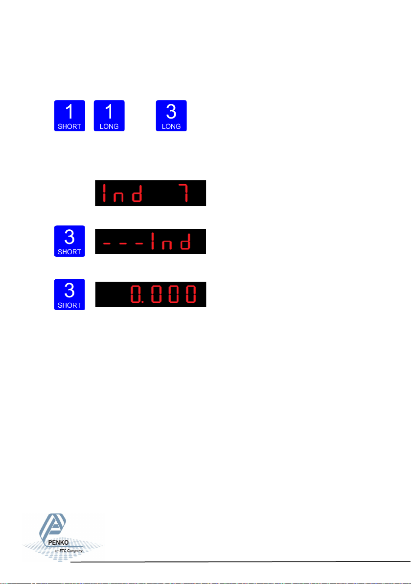
SGM800 Digizer
First use of indicator -connue-
Press key 1 to define the point position and confirm by pressing key 3
for >2 sec.
Left Right Confirm
Done succesfully, the following screen is visible:
Press key 3 <2 sec to go back to Configuration
Menu.
Press key 3 <2 sec to go back to main weigher display.
18
Page 19
SGM800 Digizer
First use of indicator -connue-
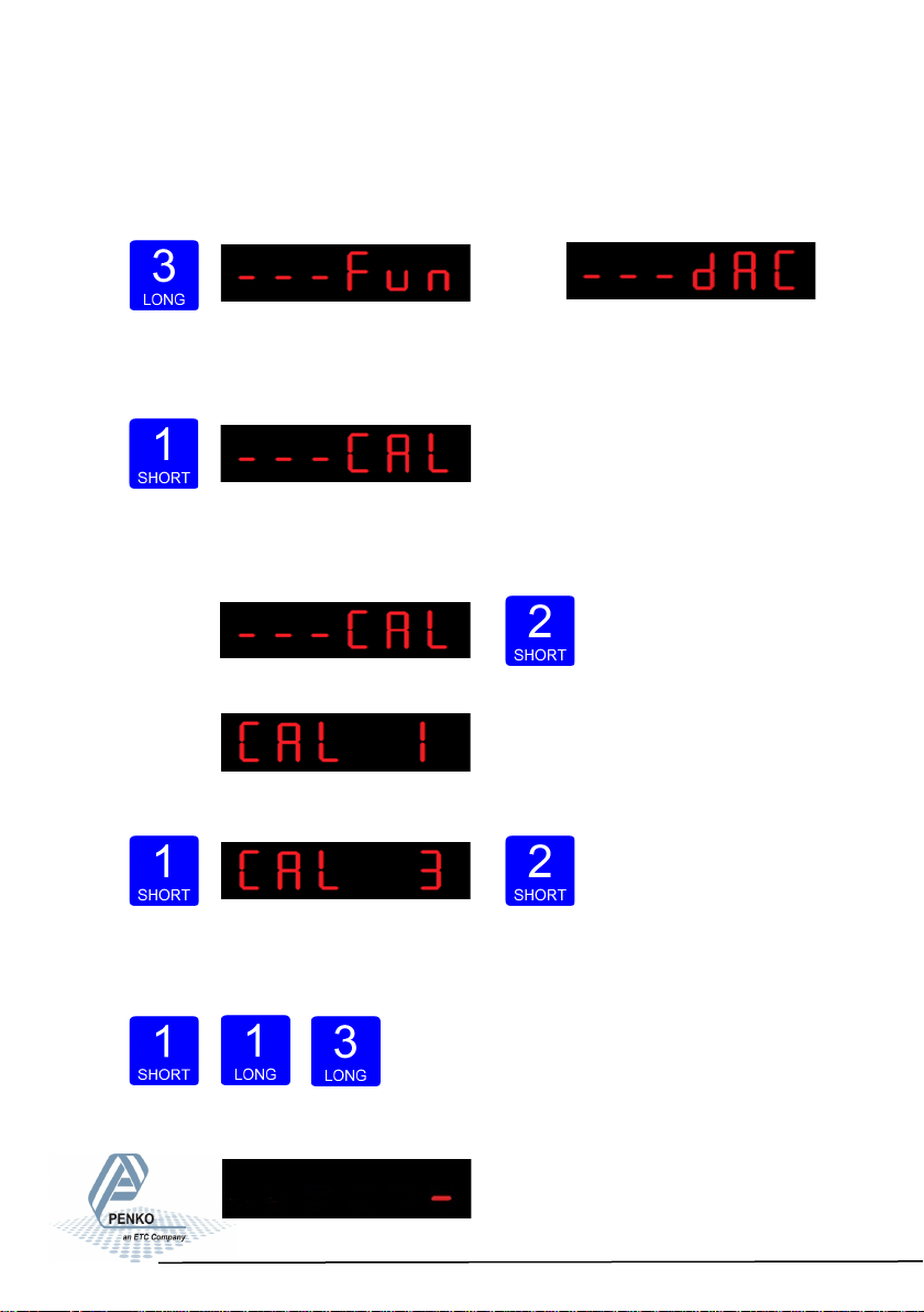
4.4 First use of indicator -CalibrationPress key 3 for >2sec. t o get in to Configuration Menu.
(In SGM810
or controller)
Go to the Calibration parameters by pressing
key 1 <2 sec. until you see - - - CAL
Check and delete calibration points.
To enter the Calibration settings, press
key 2 <2 sec.
The following screen is visible:
Press key 1 <2 sec. to go to CAL 3
and press key 2 <2 sec.
Use CAL 3 to check and delete all existing cali-
bration points. Step through the calibration
points with key 1. Delete a calibration point by pressing
key 3 >3 sec.
19
Page 20
SGM800 Digizer
First use of indicator -connue-
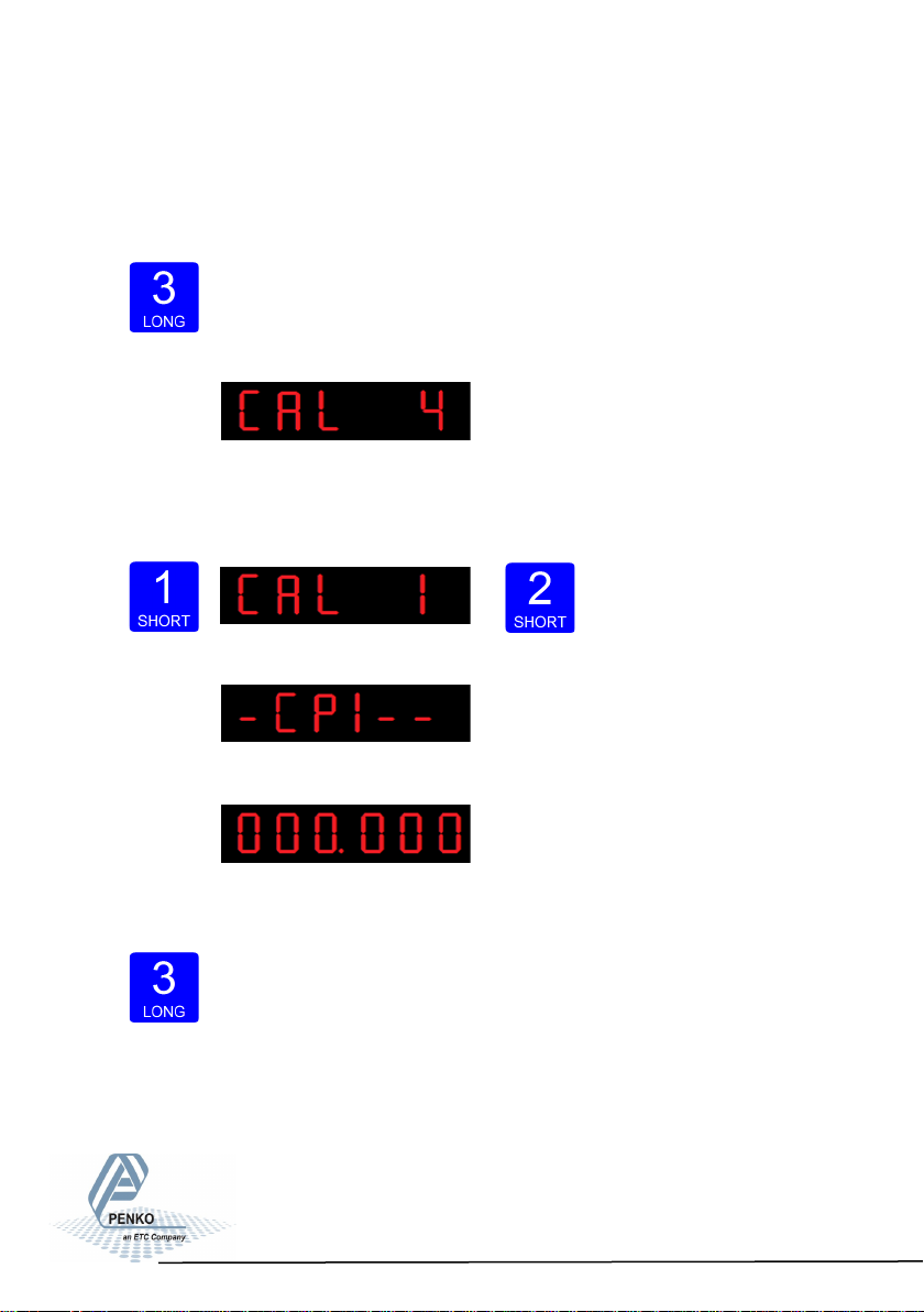
Calibration Settings -continue-
When a number is shown, the deletion of one calibration point is completed and
more points need to be deleted. Press key 3 >3 sec to do so.
>3 sec.
When all calibration points are deleted, the following screen is visible:
Entering new calibration points.
Use key 1 <2 sec. to go to CAL 1 and press key 2 <2 sec.
After entering, the following
screen is visible:
And will automatically jump to:
First calibrate the zero point (CP1). Make sure the weigher is unloaded and press
key 3 >2 sec.
20
Page 21
SGM800 Digizer
First use of indicator -connue-
Calibration Settings -continue-
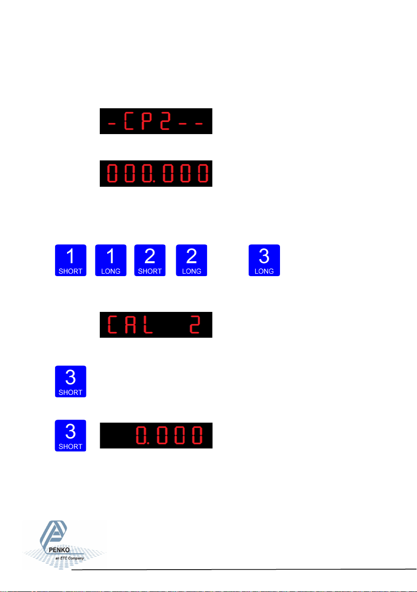
The indicator now shows CP2 to calibrate the gain point (CP2).
And will automatically jump to:
Use key 1 and key 2 to enter the reference value. Key 1 is used for changing the
number (1-9), key 2 is used for changing the position of the cursor. Load the
weigher with the reference value and press key 3 >2 sec.
Up Down
Left Right Confirm
Done succesfully the following screen is visible:
Press key 3 <2 sec. to go back to Configuration Menu.
Press key 3 <2 sec. to go back to main weigher display.
21
Page 22
SGM800 Digizer
First use of indicator -connue-
4.5 First use by using PI Mach II software
The SGM can also be configured for first use by using PI mach II software.
Download Penko Suite from the PENKO website (http://www.penko.com/db/
downloads/) and install Penko Suite. The following items will be installed:
*Pi Mach II Program Interface to configure all Penko devices
*Job Manager XE Version Control System for Pi Mach II projects
*Drivers USB drivers for latest series Penko devices
*Manuals Product manuals and protocol descriptions
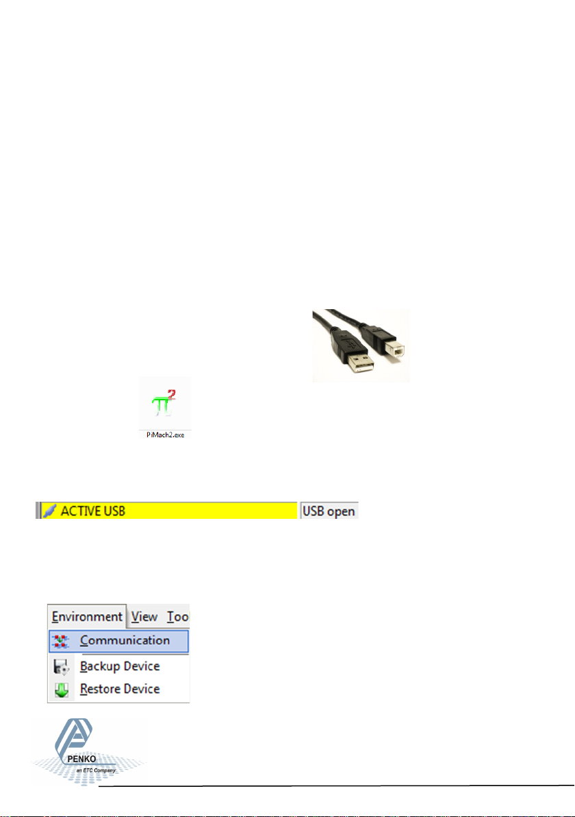
After installing, connect the SGM800 to
the computer using an A-B USB cable.
Start Pi Mach II.
The SGM800 will be found and connected. This is shown in the sta-
tus bar (lower left corner).
If there appears a USB error, connect the device manually:
Go to Environment - Communication
22
Page 23
SGM800 Digizer
First use of indicator -connue-
First use by using PI Mach II software -continue-
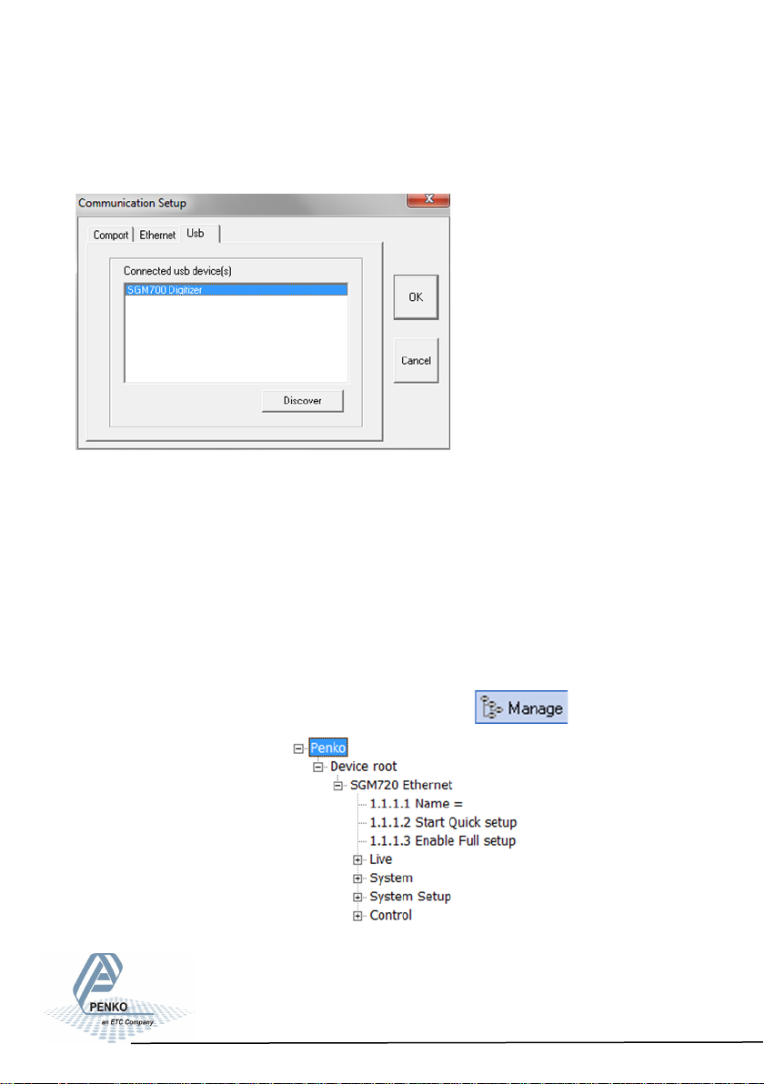
The following screen appears:
In the Usb tab sheet click Discover, select the SGM800 Digitizer and click OK.
If this doesn’t work, make sure other USB devices like mobile phones are
disconnected from the PC.
In case of Windows 8, a USB driver manual is available in the Penko Suite.
In the communication setup it’s also possible to connect the SGM820 through
Ethernet. Set the IP-address of the SGM820 in range with the PC (see chapter
6.5 of this manual) and fill in the IP-address in tab “Ethernet”.
When communication is established go to Manage.
The following tree is shown:
23
Page 24
SGM800 Digizer
First use of indicator -connue-
First use by using PI Mach II software -continue-
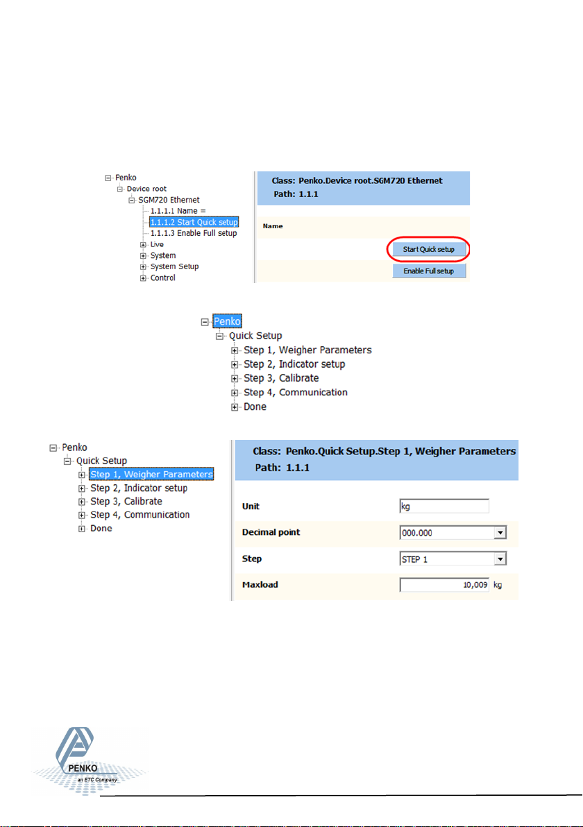
Go to Start Quick setup and click the button:
The follo- wing tree
is shown:
Use step 1 to set the Weigher Parameters:
The settings you can make are:
Unit: set the weigh er unit (kg, lbs, T, etc.) this will be show n in PI.
Decimal point: Set the decimal point to show the correct weigher value.
Step: Cho ose between 1, 2, 5, 10, 20, 50, 100, 200, 500
Maxload: Set maximum load to prevent ov erload b y the user. The ind icator
will not show any weight above the filled in value. Range: 0 – 999999.
24
Page 25
SGM800 Digizer
First use of indicator -connue-
First use by using PI Mach II software -continue-
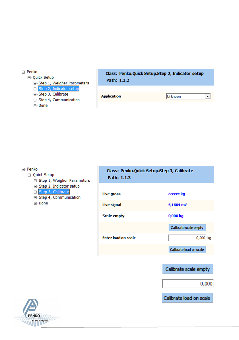
Use step 2 to select the type of indicator:
Set the type of weighing the SGM will be used for.
This will automaticly set the most common filter settings to get a stable weigher
signal. The options are: Unknown, Standard indicator, Fast indicator, Silo,
Platform, Belt slow, Belt fast, Filling slow, Filling fast, Checkweigher slow or
Checkweigher fast.
Use step 3 to calibrate the indicator:
First make sure the weigher is empty and press :
Put a refrence weight on the weigher and fill in the weight:
And confirm by pressing:
25
Page 26
SGM800 Digizer
First use of indicator -connue-
First use by using PI Mach II software -continue-
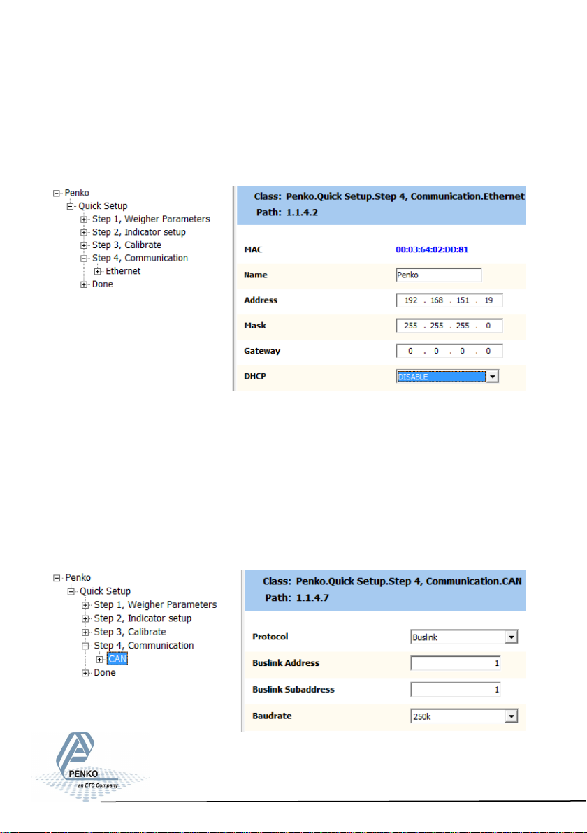
Use step 4 to set the communication (different for every type):
SGM820 (Ethernet):
Here you can set:
Name: here you can give the SGM820a name. Example “platform 1”.
Address: set the IP-address for the SGM820.
Mask: set t he subnetmask for the SGM820.
Gateway: set the Gateway for the SGM820.
DHCP: Disable/enable DHCP. When enabled the SGM820 will genarate an
IP-address for itself.
26
Page 27
SGM800 Digizer
First use of indicator -connue-
First use by using PI Mach II software -continue-
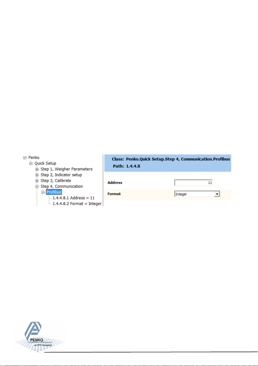
Here you can set:
Protocol: set t he Proto col fo r CANBUS. op tions are None or Buslink.
Buslink Address: Set the Buslin k Address for the comm unication between
PENKO devices.
Buslink Subaddress: Set the Buslin k Subadd ress for the co mmuni cation
between PENKO devices.
Baudrate: Set the commication speed of t he SGM830 options are: 100k, 125k,
250k, 500k. (the speed of all PENKO devices in the communication bus must be
the same).
SGM840 (PROFIBUS):
Here you can set:
Address: Set the Profibus address of the SGM840
Format: Set the format of the values sen t over Pro fibus (Integer or Floating
Point)
27
Page 28
SGM800 Digizer
First use of indicator -connue-
First use by using PI Mach II software -continue-
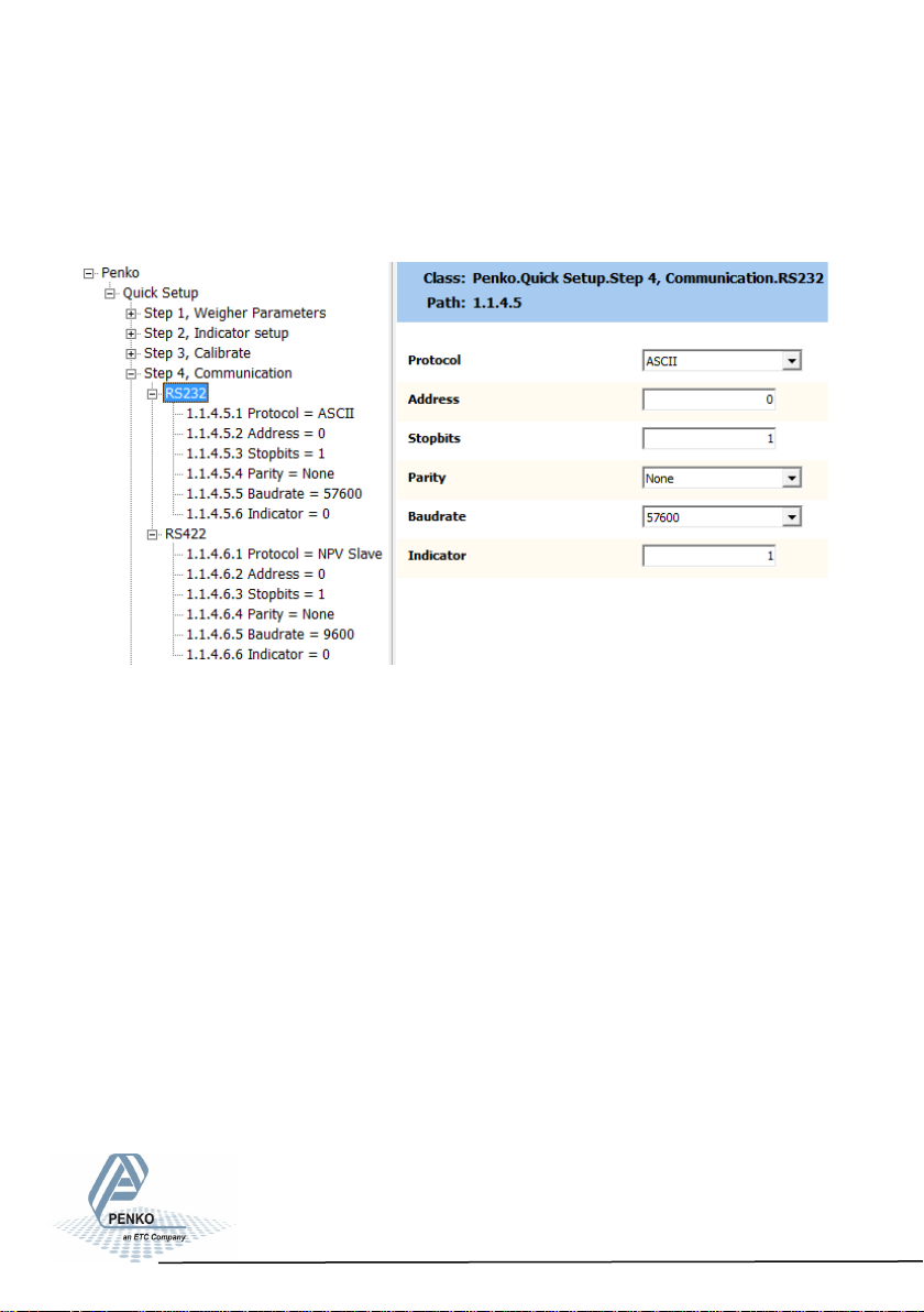
SGM850 (Serial):
Here you can set (for both RS232 and RS422):
Protocol: Set the Protocol that is used on the serial port. Options are: None,
Printerm ASCII, NPV Slave, Mudbus RTU, Modbus ASCII.
Address: set the addres s of the SGM850 on the co mmuni cation bus.
Stopbits: set the sto pbits of the SGM850 on the com munication bus.
Paritiy: set the pari t y of the SGM850 on the communi cation bus. Options ar e:
None, Odd, Even, Mark, Space.
Baudrate: set the speed c ummunicatio n of th e SGM850. Opt ions are: 1200,
2400, 4800, 9600, 19200, 38400, 57600, 115200.
Indicator: Set th e Indicat or that is sent out ov er the co mmuni cation bus.
28
Page 29
SGM800 Digitizer
First use of indicator -connue-
First use by using PI Mach II software -continue-
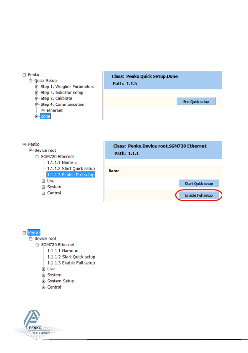
Use Done to finish the quick setup. Click End Quick setup:
Click Enable Full setup to gain access to all settings (optional):
The following tree is shown and gives access to all settings:
29
Page 30
SGM800 Digizer
5. Main Menu
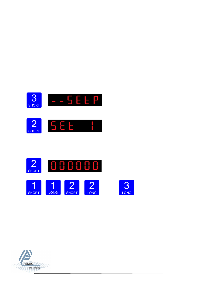
In the Main menu you can change the Setpoints (this option is not available in
the SGM810 or controllers), display the TAC code and display the CAL code.
5.1 Setpoints. (this option is not available in the SGM810)
The SGM800 has four outputs that can switch on/off on different levels.
These levels have to be filled in at the setpoint menu.
Press key 3 <2 sec. to go into the Main menu.
Press key 2 <2sec. to the setpoint change menu.
Press key 1 <2 sec. to select a diffrent set-
point (1-4). Press key 2 <2 sec. to change the selected setpoint. Key 1 is used for
changing the number (1-9), key 2 is used for changing the position of the cursor.
Press key 3 >2sec. to confirm.
Up Down
Left Right Confirm
When the selected setpoint is changed, the display changes to the next setpoint.
30
Page 31
SGM800 Digizer
Main Menu -connue-
When done with changing the setpoints press key 3 <2 sec to go back to the
main weigher display
5.2 TAC code (Traceable Acces Code).
The SGM800 has a TAC code inside. TAC code is number of times the indicator
data is changed. When an indicator gets certified this number will be written on
the device and is used by the controlling agency to see if the settings aren’t
changed after sealing.
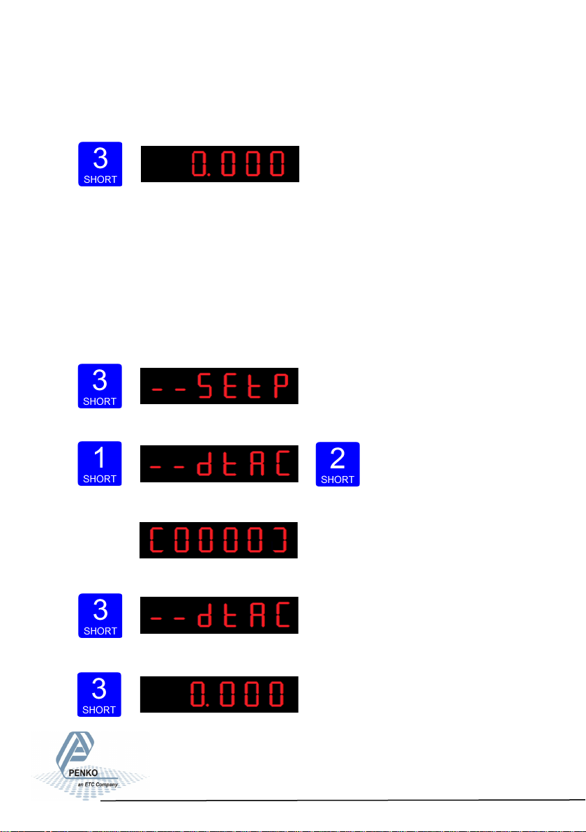
To check out the TAC code Press key 3 <2 sec. to go into the Main menu.
Press key 1 <2sec. to the dtAC menu and
press key 2 <2sec. to enter.
The following screen will show the actual TAC code.
Press Key 3 <2 sec. to go back to the main menu.
Press key 3 <2 sec. to go back to the main weigher display.
31
Page 32
SGM800 Digizer
Main Menu -connue-
5.2 CAL code (Calibration counter).
The SGM800 has a CAL code inside. CAL code is the number of times the
calibration is changed. When an indicator gets certified this number will be written
on the device and is used by the controlling agency to see if the settings aren’t
changed after sealing.
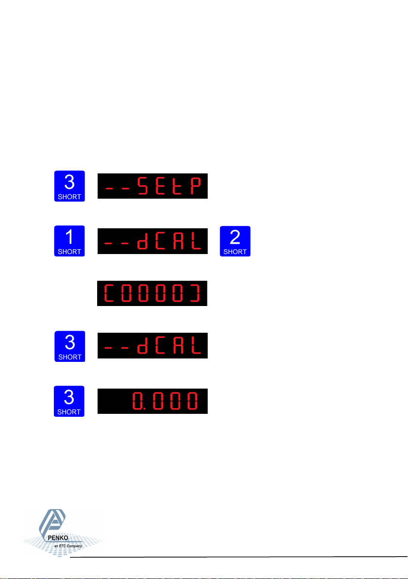
To check out the CAL code Press key 3 <2 sec. to go into the Main menu.
Press key 1 <2sec. 2x to the dCAL menu
and press key 2 <2sec. to enter.
The following screen will show the actual CAL code.
Press Key 3 <2 sec. to go back to the main menu.
Press key 3 <2 sec. to go back to the main weigher display.
32
Page 33
SGM800 Digizer
6. Conguraon Menu
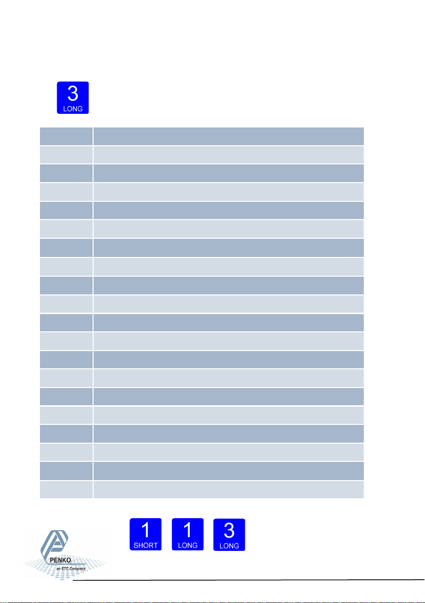
Press button 3 >2 sec to enter the Configuration Menu.
In the Configuration Menu the following options are available:
- - - Fun setpoint function settings (not for SGM810)
- - - Fun setpoint function settings (not for SGM810 or controller)
- - - ACn setpoint action settings (not for SGM810)
- - - ACn setpoint action settings (not for SGM810 or controller)
- - - dAC Analog output settings
- - - dAC Analog output settings
- - - 485 Local bus communication settings (RS485)
- - - 485 Local bus communication settings (RS485)
- - - Eth Ethernet settings (SGM820 only)
- - - Eth Ethernet settings (SGM820 only)
- - - CAn Can bus port settings (SGM830 only)
- - - CAn Can bus port settings (SGM830 only)
- - - - Pb Profibus settings (SGM840 only)
- - - - Pb Profibus settings (SGM840 only)
- - - 232 RS232 port settings (SGM850 only)
- - - 232 RS232 port settings (SGM850 only)
- - - 422 RS422 port settings (SGM850 only)
- - - 422 RS422 port settings (SGM850 only)
- - - Ind Indicator settings
- - - Ind Indicator settings
- - - rng Multi range/interval settings
- - - rng Multi range/interval settings
- - - FIL Filter settings
- - - FIL Filter settings
- - - dSF Digital filter settings
- - - dSF Digital filter settings
- - - PCL Pre-calibration settings
- - - PCL Pre-calibration settings
- - - CAL Calibration settings
- - - CAL Calibration settings
- - - tCL Theoretic calibration
- - - tCL Theoretic calibration
- - - gCL Geographic calibration
- - - gCL Geographic calibration
- - - CLo Date and time configuration (SGM850 only)
- - - CLo Date and time configuration
- - - rcL Recall
- - - rcL Recall
- - - SoF Firmware update
- - - SoF Firmware update
Scroll thru the menu options pressing key 1 and en-
ter a sub-menu pres- sing
key 2 <2 sec.
33
Page 34
SGM800 Digitizer
Conguraon Menu -Fun-
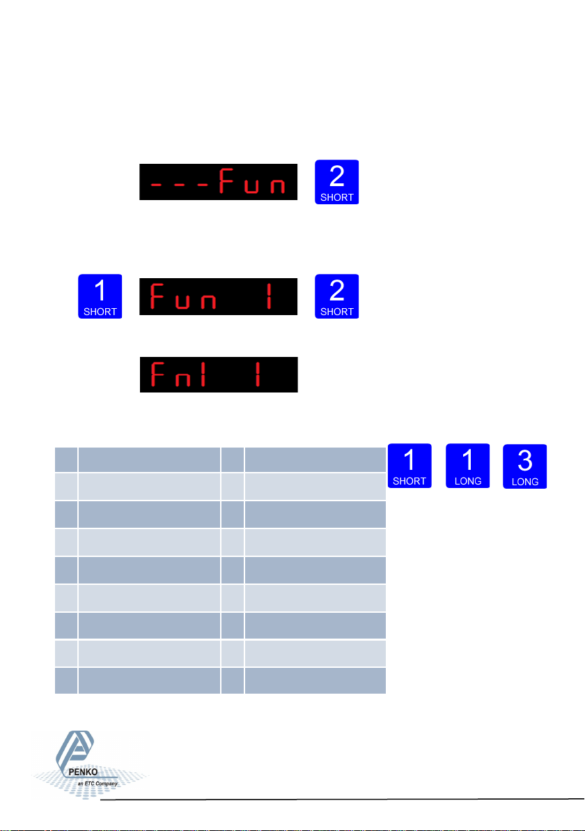
6.1 - - - Fun setpoint function settings (not for SGM810 or controller)
Configure the weiger mode the outputs has to switch on press key 2 <2 sec to
enter the setpoint function settings menu.
Select the output you want to configure pressing key 1 <2 sec. Fun 1= output 1,
Fun 2= output 2, Fun 3= output 3 and Fun 4= output 4. Confirm the selected output
by pressing key 2 <2 sec.
The following screen is visible:
Scroll thru the weigher function options pressing key 1
and select which weigher mode is needed by pressing key 3 >2sec. (options are: 1
-17)
1 Weigher 10 Fast gross x 10
2 Fast gross 11 Fast Net x 10
3 Fast net 12 Display Gross x 10
4 Display Gross 13 Display Net x 10
5 Display Net 14 Tare x 10
6 Tare 15 Peak x 10
7 Peak 16 Valley x 10
8 Valley 17 Sample
9 Weigher x 10
For further detais on the weigher functions check appendix I
Up Down Confirm
34
Page 35
SGM800 Digizer
Conguraon Menu -ACn-
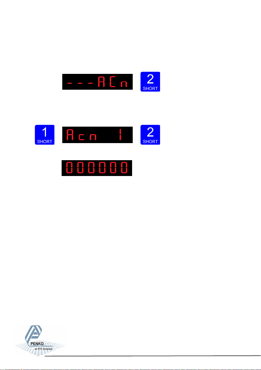
6.2 - - - ACn setpoint action settings (not for SGM810 or controller)
To set the hysteresis for the outputs press key 2 <2 sec to enter the setpoint
function settings menu.
Select the output you want to configure pressing key 1 <2 sec. Acn 1= output 1,
Acn 2= output 2, Acn 3= output 3 and Acn 4= output 4. Confirm the selected out-
put by pressing key 2 <2 sec.
The following screen is vissable:
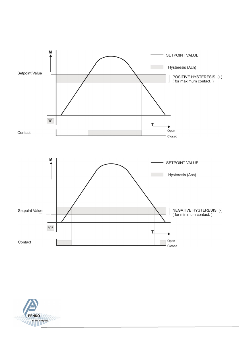
Fill in the hyste- resis for the outputs. Use key 1 and 2
to change the value. Key 1 is for changing the number (1-9), key 2 is for changing
the position of the cursor. Confirm by pressing key 3 for >2 sec.See diagram next
page.
Choose value between -99999 and 999999.
35
Page 36
SGM800 Digizer
Conguraon Menu -ACn- -connue-
Positive hysteresis
Negative hysteresis
36
Page 37
SGM800 Digizer
Conguraon Menu -dAC-
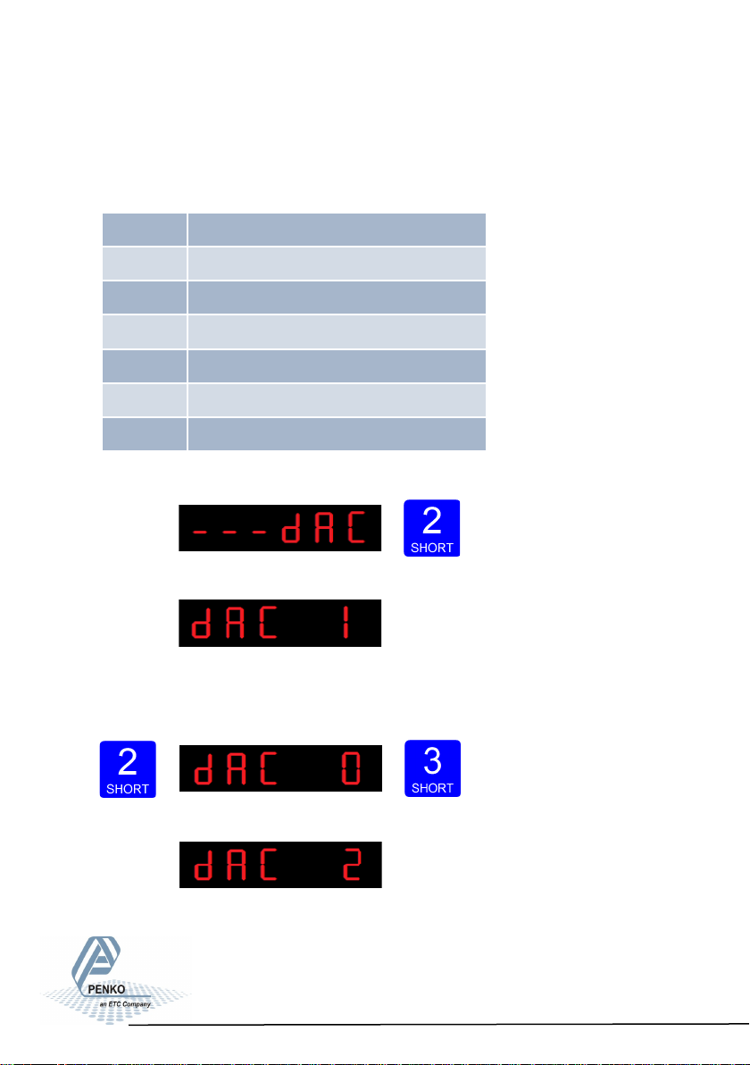
6.3 - - - dAC Analog output settings
In this menu, all analog output parameters can be set (only for SGM810 or when
the analog output option is installed).Options are:
Press key 2 <2 sec to enter the
analog output settings.
The following screen is visible:
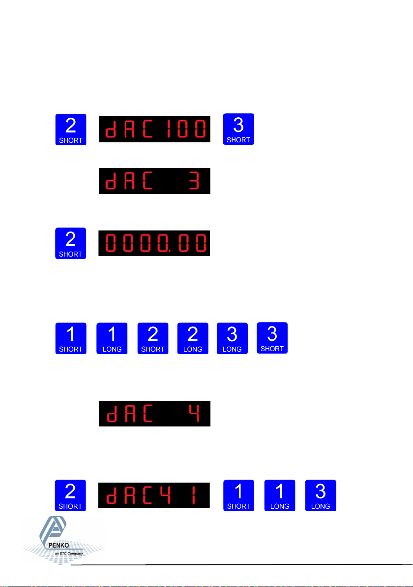
In dAC 1 you can set the analog output to its minimum level for testing
purpose.Press key 2 <2 sec to set the analog output to minimum.
Press key 3 <2 sec to go back.
The following screen is vissable:
dAC 1 Set analog output to minimum level
dAC 2 Set analog output to maximum level
dAC 3 Set analog output to level in percetage
dAC 4 Analog output weigher mode
dAC 5 Zero value for minimum analog output
dAC 6 End value for maximum analog output
dAC 7 Analog output range
37
Page 38
SGM800 Digizer
Conguraon Menu -dAC- -connue-
In dAC 2 you can set the analog output to its maximum level for testing purpo-
se.Press key 2 <2 sec to set the analog output to maximum. Press key 3 <2 sec
to go back.
The following screen is vissable:
In dAC 3 you can set the analog output to a level
you want for testing purpose.
Press key 2 <2 sec.
Fill in the wanted percentage (0000,00-0100,00 using key 1 and key 2. Key 1 is
for changing the number (1-9), key 2 is for changing the position of the cursor.
Confirm by pressing key 3 >2 sec. Press key 3 <2 sec. to go back and reset the
analog output.
Increase Decrease
Left Right Confirm Go back
The following screen is vissable:
In dAC 4 you set the weigher mode that the analog output is based on. Press key
2 < 2sec. to enter dAC 4. Scroll thru the weigher function options pressing key 1
and select
which weigher
mode is needed by pres-
sing key 3 >2sec. (options are: 1-17)
38
Page 39
SGM800 Digizer
Conguraon Menu -dAC- -connue-
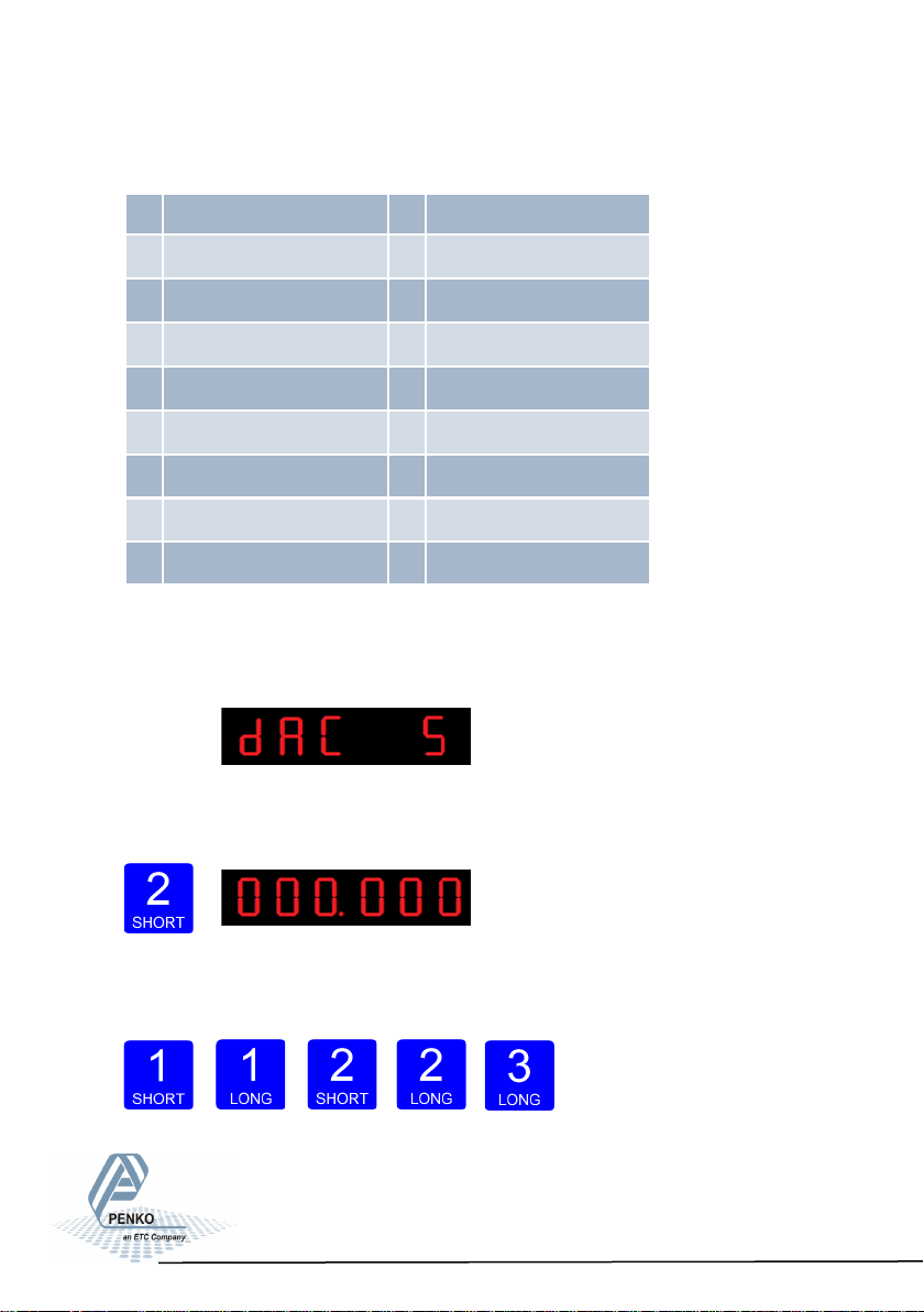
The options are:
For further detais on
the weigher functions check appendix I
The following screen will be vissable:
In dAC 5 you set the weigher start value for the analog output. At this value the
analog output starts with its minimum value. Press key 2 < 2sec. to enter dAC 5.
Fill in the wanted start weight using key 1
and key 2. Key 1 is for changing the number (1-9), key 2 is for changing the position of the cursor.
Confirm by pressing key 3 >2 sec.
Increase Decrease Left Right Confirm
1 Weigher 10 Fast gross x 10
2 Fast gross 11 Fast Net x 10
3 Fast net 12 Display Gross x 10
4 Display Gross 13 Display Net x 10
5 Display Net 14 Tare x 10
6 Tare 15 Peak x 10
7 Peak 16 Valley x 10
8 Valley 17 Sample
9 Weigher x 10
39
Page 40
SGM800 Digizer
Configuration Menu -dAC- -continue-
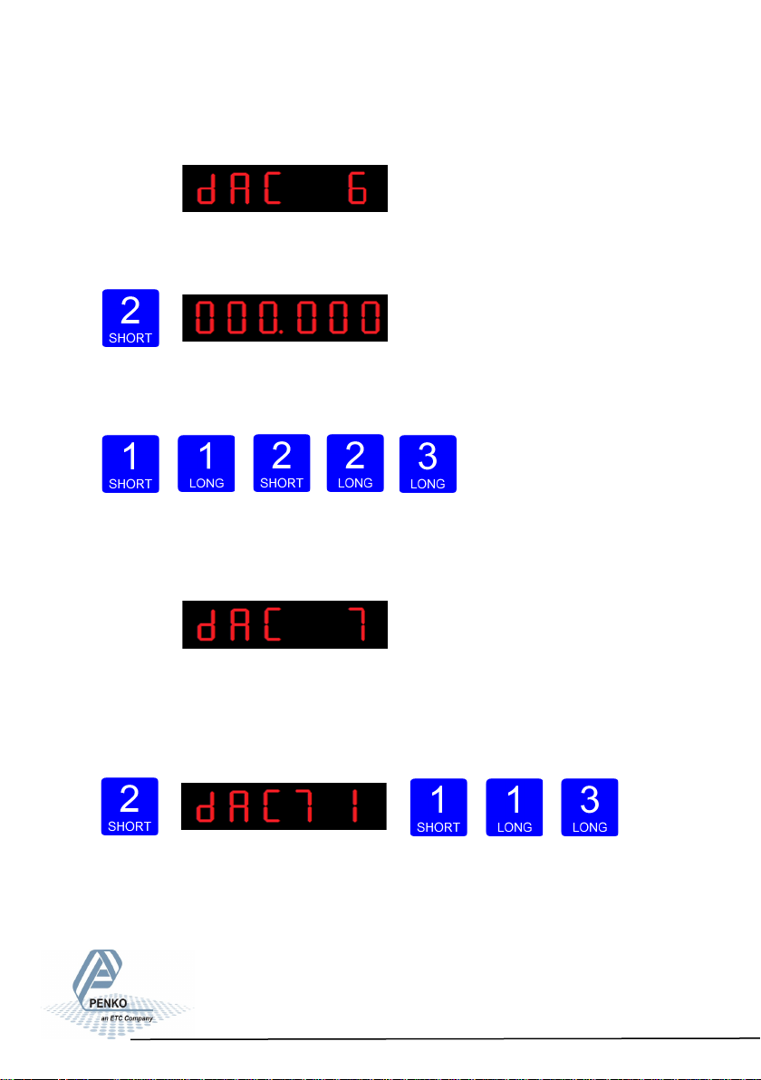
The following screen will be vissable:
In dAC 6 you set the weigher end value for the analog output. At this value the
analog output stops with its maximum value. Press key 2 < 2sec. to enter dAC 6.
Fill in the wanted end value using key 1 and
key 2. Key 1 is for changing the number (1-9), key 2 is for changing the position
of the cursor. Confirm by pressing key 3 >2 sec.
Increase Decrease Left
Right Confirm
The following screen will be vissable:
In dAC 7 you set analog output mode. Press key 2 < 2sec. to enter dAC 7. Scroll
thru the weigher function options pressing key 1 and select which analog output
mode is needed by pressing key 3 >2sec. (options are: 1-5).
Increase Decrease Confirm
40
Page 41
SGM800 Digizer
Conguraon Menu -dAC- -connue-
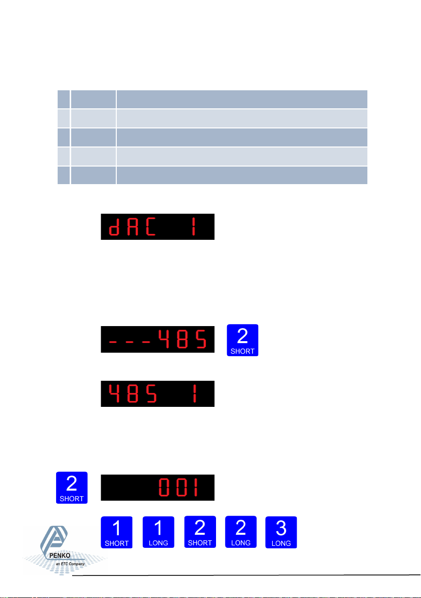
Options are:
When confirmed the following screen will be vissable:
Configura- tion Menu -485-
6.4 - - - 485 Local bus communication settings (RS485)
In this menu, the communication address can be set for communication with
multiple devices. Press key 2 <2 sec to enter the settings.
The following screen will be vissable:
In 485 1 you set the address of the SGM800. Press
key 2 < 2sec. to enter 485 1. Set the address using key 1 and key 2.. Key 1 is for
changing the number
(1-9), key 2 is for changing the position of the cursor. Confirm by pressing
key 3 >2sec. (options are: 1-32).
Increase
Decrease Left Right Confirm
1 RAW Register value 65535 parts
2 0-24mA input value 0 to 24 mA will be calculated from 0 to 100,00%
3 0-20mA input value 0 to 20 mA will be calculated from 0 to 100,00%
4 4-20mA input value 4 to 20 mA will be calculated from 0 to 100,00%
5 4-24mA input value 4 to 24 mA will be calculated from 0 to 100,00%
41
Page 42
SGM800 Digizer
Conguraon Menu -Eth-
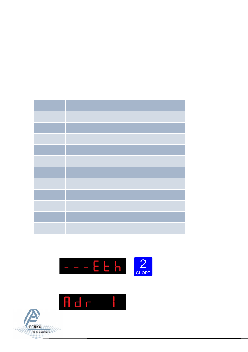
6.5 - - - Eth Ethernet settings (SGM820 only)
Protocols that can be used are Ethernet IP, Omron Fins and Modbus TCP.
For protocol description please download PENKO Suite from www.penko.com
In this menu, the communication settings can be set for the ethernet port.
Options are:
Press key 2 <2 sec to
enter the ethernet settings.
The following screen is vissable:
Adr 1 First three numbers of the IP address
Adr 2 Second three numbers of the IP address
Adr 3 Third three numbers of the IP address
Adr 4 Fourth three numbers of the IP address
Sub 1 First three numbers of the Subnet address
Sub 2 Second three numbers of the Subnet address
Sub 3 Third three numbers of the Subnet address
Sub 4 Fourth three numbers of the Subnet address
gAt 1 First three numbers of the Gateway address
gAt 2 Second three numbers of the Gateway address
gAt 3 Third three numbers of the Gateway address
gAt 4 Fourth three numbers of the Gateway address
42
Page 43
SGM800 Digizer
Conguraon Menu -Eth- -connue-
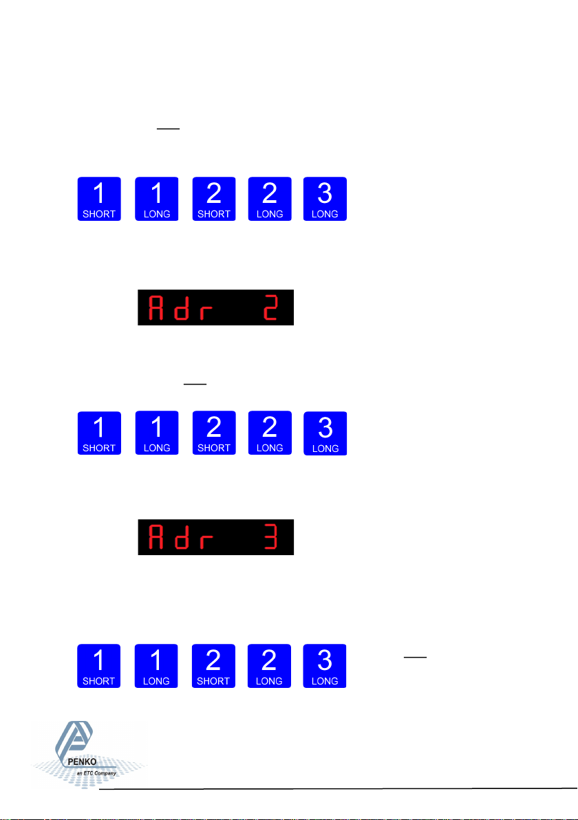
In Adr 1 you set the first three numbers of the IP address you want to give the
SGM820 (example: 192.168.151.112). Use key 1 and key 2 to change the
number Key 1 is for changing the number (1-9), key 2 is for changing the position
of the cursor. Confirm by pressing key 3 >2 sec.
Increase Decrease Left
Right Confirm
When confir- med the following screen will be visi-
ble:
In Adr 2 you set the second three numbers of the IP address you want to give the
SGM820 (example: 192.168.151.112). Use key 1 and key 2 to change the num-
ber Key 1 is for changing the number (1-9), key 2 is for changing the position of
the cursor. and confirm by pres-
sing key 3 >2 sec.
Increase Decrease Left Right Confirm
When confir- med the following screen will be visi-
ble:
In Adr 3 you set the third three numbers of the IP address you want to give the
SGM820 (example:
192.168.151.112). Use key 1
and key 2 to change the
num- ber Key 1 is for changing the
number (1-9), key 2 is for changing the position of the cursor. Confirm by pressing key 3 >2 sec.
43
Page 44
SGM800 Digizer
Conguraon Menu -Eth- -connue-
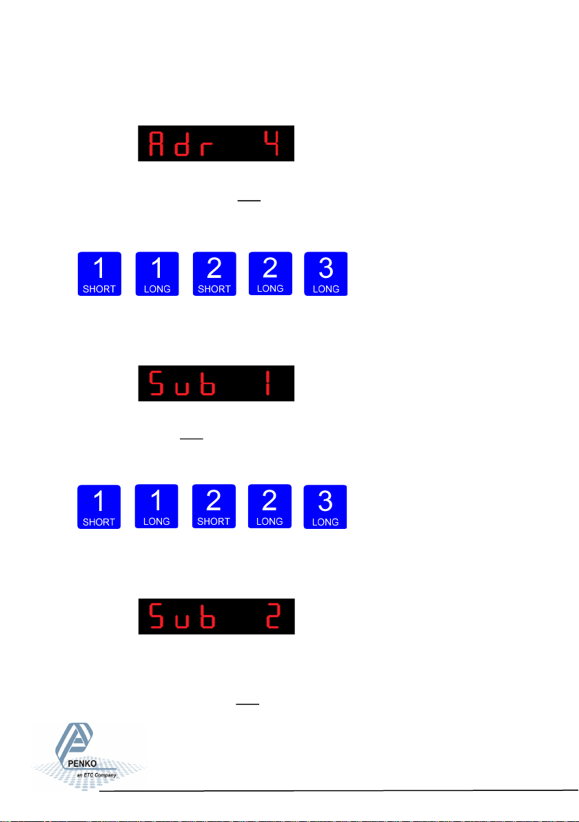
When confirmed the following screen will be visible:
In Adr 4 you set the fourth three numbers of the IP address you want to give the
SGM820 (example: 192.168.151.112). Use key 1 and key 2 to change the num-
ber Key 1 is for changing the number (1-9), key 2 is for changing the position of
the cursor. Confirm by pressing key 3 >2 sec.
Increase Decrease Left
Right Confirm
When confirmed the following screen will be visible:
In Sub 1 you set the first three numbers of the Subnet address you want to give
the SGM820 (example: 255.255.255.000). Use key 1 and key 2 to change the
number Key 1 is for changing the number (1-9), key 2 is for changing the position
of the cursor. Confirm by pressing key 3 >2 sec.
Increase Decrease Left
Right Confirm
When confir- med the following screen will be visi-
ble:
In Sub 2 you set the second three numbers of the Subnet address you want to
give the SGM820 (example: 255.255.255.000). Use key 1 and key 2 to change
the number Key 1 is for changing the number (1-9), key 2 is for changing the po-
sition of the cursor. Confirm by pressing key 3 >2 sec.
44
Page 45
SGM800 Digizer
Conguraon Menu -Eth- -connue-
Increase Decrease Left Right Confirm
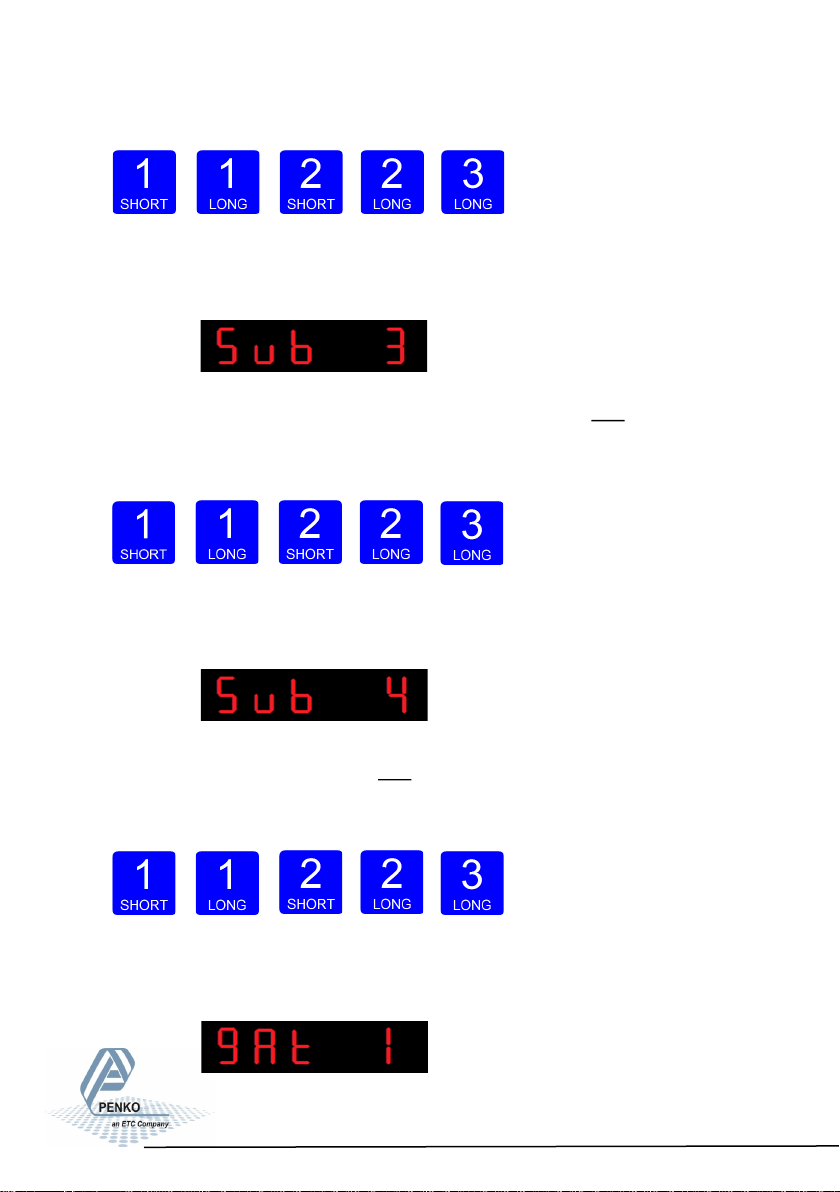
When confirmed the following screen will be visible:
In Sub 3 you set the third three numbers of the Subnet
address yo u want to give the SGM820 (example: 255.255.255.000). Use key 1
and key 2 to change the number Key 1 is for changing the number (1-9), key 2 is
for changing the position of the cursor. Confirm by pressing key 3 >2 sec.
Increase Decrease Left
Right Confirm
When confirmed the following screen will be visible:
In Sub 4 you set the fourth three numbers of the Subnet address you want to give
the SGM820 (example: 255.255.255.000). Use key 1 and key 2 to change the
number Key 1 is for changing the number (1-9), key 2 is for changing the position
of the cursor. Confirm by pressing key 3 >2 sec.
Increase Decrease Left
Right Confirm
When confirmed the following screen will be visible:
45
Page 46
SGM800 Digizer
Conguraon Menu -Eth- -connue-
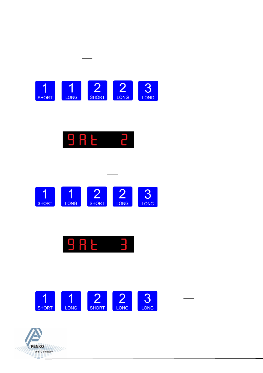
In gAt 1 you set the first first numbers of the Gateway address you want to give
the SGM820 (example: 192.168.001.001). Use key 1 and key 2 to change the
number Key 1 is for changing the number (1-9), key 2 is for changing the position
of the cursor. Confirm by pressing key 3 >2 sec.
Increase Decrease Left
Right Confirm
When confir- med the following screen will be visi-
ble:
In gAt 2 you set the second three numbers of the Gateway address you want to
give the SGM820 (example: 192.168.001.001). Use key 1 and key 2 to change
the number Key 1 is for changing the number (1-9), key 2 is for changing the po-
sition of the cursor. Confirm by
pres- sing key 3 >2 sec.
Increase Decrease Left Right Confirm
When confir- med the following screen will be visi-
ble:
In gAt 3 you set the third three numbers of the Gateway address you want to give
the SGM820 (example:
192.168.001.001). Use key 1
and key 2 to change the number
Key 1 is for changing the number (1
-9), key 2 is for changing the position of the cursor. Confirm by pressing key 3 >2
sec.
46
Page 47
SGM800 Digizer
Conguraon Menu -Eth- -connue-
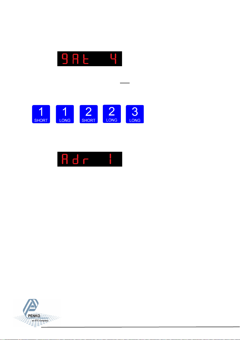
When confirmed the following screen will be visible:
In gAt 4 you set the fourth three numbers of the Gateway address you want to
give the SGM820 (example: 192.168.001.001). Use key 1 and key 2 to change
the number Key 1 is for changing the number (1-9), key 2 is for changing the po-
sition of the cursor. Confirm by pressing key 3 >2 sec.
Increase Decrease Left
Right Confirm
When confirmed the following screen will be visible:
Starting at firmware version 1.5.0.9.0.1 the PENKO ASCII protocol is available
over TCP at port 23.
47
Page 48

SGM800 Digizer
Conguraon Menu –Can-
6.6 - - - Can Canbus settings (SGM830 only)
The protocol that can be used is PENKO CAN Buslink
(CANopen is not supported).
For protocol description please download PENKO Suite from www.penko.com
In this menu, the communication settings can be set for profibus.
Options are:
Press key 2 <2 sec to
enter the Canbus settings.
The following screen will be vissable:
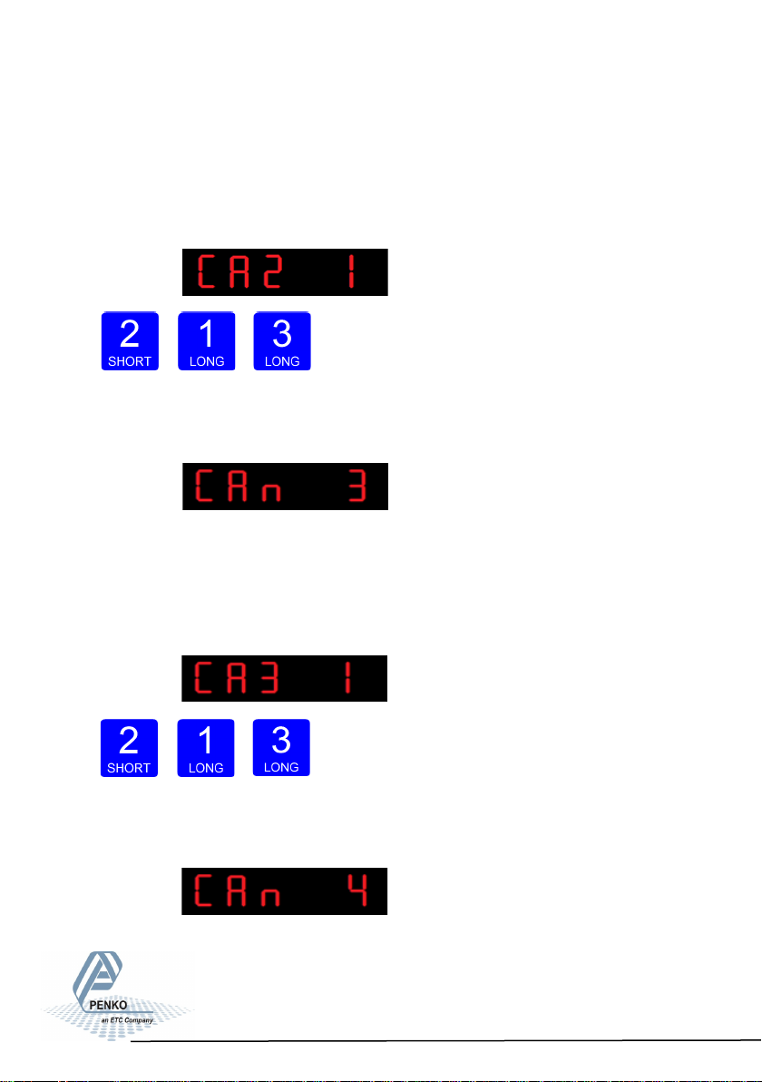
In CAn 1 you set the Canbus protocol of the SGM800. Press key 2 <2 sec. to enter
CAn 1. Set the protocol using key 1 and key 2 confirm by pressing key 3 >2 sec. 1=
none, 2= Buslink
Increase Decrease Confirm
When confirmd the following screen will be vissable:
CAn 1 Communicaon protocol
CAn 2 Busslink address
CAn 3 Busslink subaddress
CAn 4 Baudrate
48
Page 49
SGM800 Digizer
Conguraon Menu –Can- -connue-
In CAn 2 you set the Canbus address of the SGM800. Up to 8 devices can com-
municate with eachother, sharing inputs, outputs, markers and indicators. Press
key 2 <2 sec. to enter CAn 2. Set the address using key 1 and key 2 confirm by
pressing key 3 >2 sec. (options are: 1-8).
Increase Decrease Confirm
When confirmd the following screen will be vissable:
In CAn 3 you set the Canbus subaddress of the SGM800. When using a subad-
dress, up to 40 devices can communicate with each other. Press key 2 <2 sec. to
enter CAn 2. Set the address using key 1 and key 2 confirm by pressing key 3
>2 sec. (options are: 1-5).
Increase Decrease Confirm
When confirmd the following screen will be vissable:
49
Page 50
SGM800 Digizer
Conguraon Menu –Can- -connue-
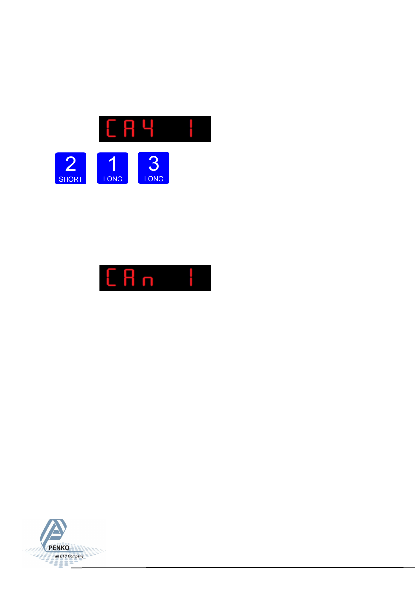
In CAn 4 you set the Canbus Baudrate of the SGM800. Set the communication
speed using key 1 and key 2 confirm by pressing key 3 >2 sec. (options are: 1=
100kbps, 2=125kbps, 3=250kbps and 4=500kbps).
Increase Decrease Confirm
When confirm the following screen will be vissable:
50
Page 51
SGM800 Digizer
Conguraon Menu –Pb-
6.7 - - - - Pb Profibus settings (SGM840 only)
For GSD file and protocol description please download PENKO Suite from
www.penko.com.
In this menu, the communication settings can be set for profibus.
Options are:
Press key 2 <2 sec to enter the profibus settings.
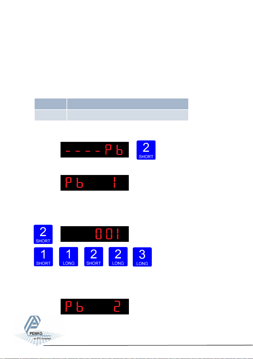
The following screen will be vissable:
In Pb 1 you set the profibus address of the SGM840.
Press key 2 <2 sec. to enter Pb 1. Set the address using key 1 and key 2 confirm
by pressing key 3 >2 sec. (options are: 0-255).
Increase Decrease Left
Right Confirm
When confirmd the following screen will be vissable:
Pb 1 Probus address
Pb 2 Value mode
51
Page 52
SGM800 Digizer
Conguraon Menu -Pb- -connue-
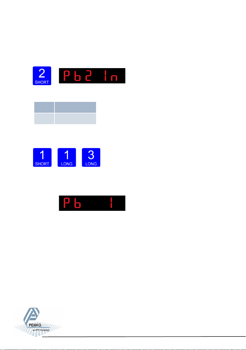
In Pb 2 you set the profibus Value mode. The profibus value can be shown as
Integer (direct value without decimal point) or as Floating Point (real value with
decimal point). Press key 2 <2 sec. to change the mode.
The oprions are:
Select the option you want to use by pressing key 1 and
confirm by pressing
key 3 >2 sec.
Increase Decrease Confirm
The following screen will be vissable:
Note: after a recall or a firmware update, the Profibus needs to be reset. This is
done by power down the device and power it up again.
Pb2 FL Floang point
Pb2 In Integer
52
Page 53
SGM800 Digizer
Conguraon Menu –232-
6.8 - - - 232 RS232 Port settings (SGM850 only)
In this menu, the communication settings can be set for RS232 communication.
Options are:
Press key 2 <2 sec to
enter the RS232 port settings.
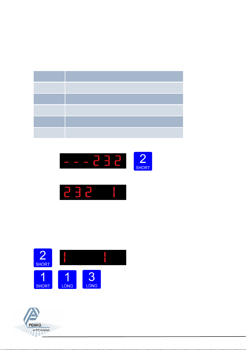
The following screen will be vissable:
In 232 1 you set the RS232 Protocol of the SGM850. Press key 2 <2 sec. to en-
ter 232 1. Set the Prot using key 1 and key 2 confirm by pressing key 3 >2 sec.
(options are: 1= None, 2= Printer, 3= ASCII, 4= NPV Slave, 5= Modbus-RTU, 6=
Modbus ASCII). For protocol descriptions please download PENKO Suite from
www.penko.com
Increase Decrease Confirm
232 1 Protocol
232 2 Address
232 3 Stopbits
232 4 Parity
232 5 Baudrate
232 6 Indicator
53
Page 54
SGM800 Digizer
Conguraon Menu –232- -connue-
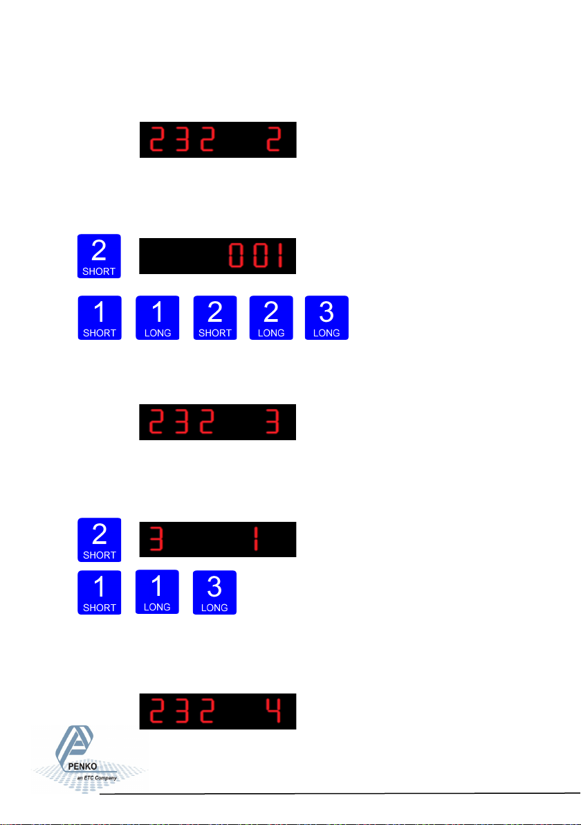
When confirmd the following screen will be vissable:
In 232 2 you set the RS232 address of the SGM850. Press key 2 <2 sec. to enter
232 2 Set the address using key 1 and key 2 confirm by pressing key 3 >2 sec.
(options are: 0-255).
Increase Decrease Left
Right Confirm
When confirmd the following screen will be vissable:
In 232 3 you set the RS232 stopbits of the SGM850. Press key 2 <2 sec. to enter
232 3. Set the number of stopbits the protocol needs by using key 1 and key 2
confirm by pressing key 3 >2 sec. (options are: 1-2).
Increase De- crease Confirm
When confirmd the following screen will be vissable:
54
Page 55
SGM800 Digizer
Conguraon Menu –232- -connue-
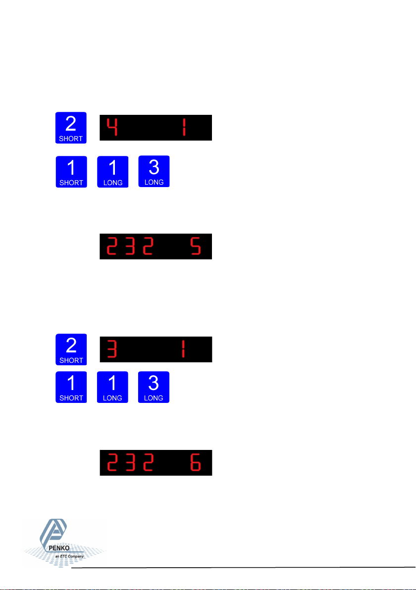
In 232 4 you set the RS232 Parity of the SGM850. Press key 2 <2 sec. to enter
232 4 Set the Parity using key 1 and key 2 confirm by pressing key 3 >2 sec.
(options are: 1= none, 2= odd, 3= even, 4= mark, 5=space).
Increase Decrease Confirm
When confirmd the following screen will be vissable:
In 232 5 you set the RS232 Baudrate of the SGM850. Press key 2 <2 sec. to en-
ter 232 5. Set the speed of the protocol by using key 1 and key 2 confirm by pressing key 3 >2 sec. (options are: 1=1200, 2= 2400, 3= 4800, 4= 9600, 5= 19200,
6= 38400, 7= 57600, 8= 115200 kbps).
Increase Decrease Confirm
When confirmd the following screen will be vissable:
55
Page 56
SGM800 Digizer
Conguraon Menu –232- -connue-
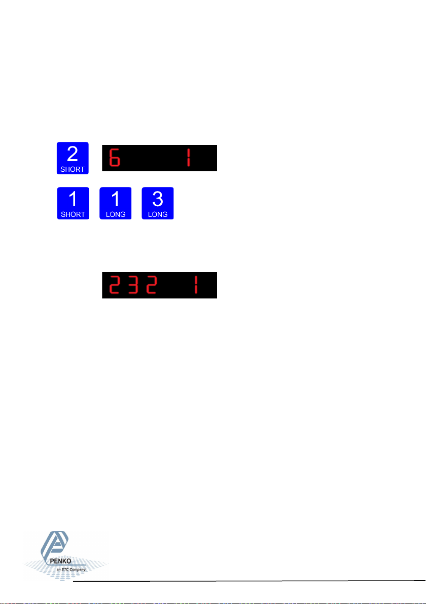
In 232 6 you set the RS232 ASCII Indicator of the SGM850. This setting only ta-
kes effect when using the ASCII protocol. Press key 2 <2 sec. to enter 232 6 Set
the Indicator numer that you want to sent out over the RS232 port by using key 1
and key 2 confirm by pressing key 3 >2 sec. (options are: 1-100).
Increase Decrease Confirm
When confirmd the following screen will be vissable:
56
Page 57
SGM800 Digizer
Conguraon Menu –422-
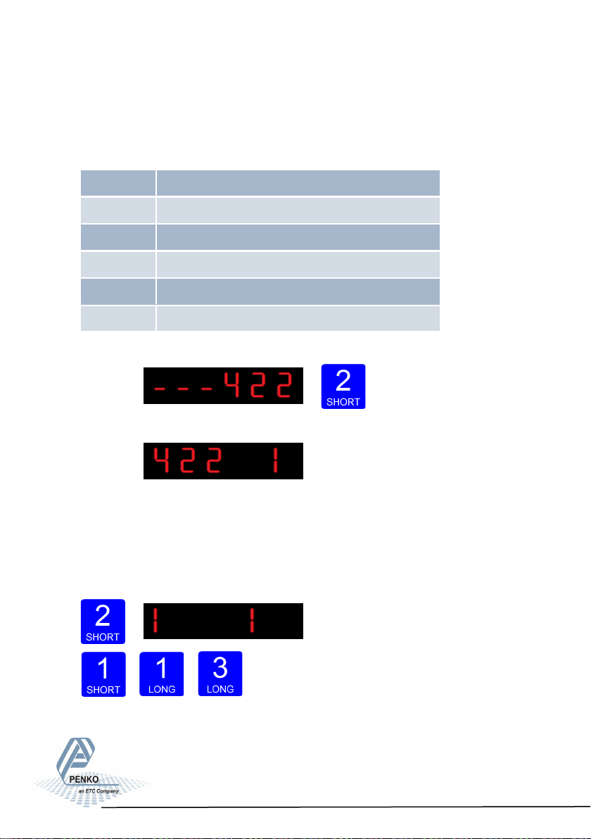
6.9 - - - 422 RS422 Port settings (SGM850 only)
In this menu, the communication settings can be set for RS422 communication.
Options are:
Press key 2 <2 sec to
enter the RS422 port settings.
The following screen will be vissable:
In 422 1 you set the RS422 Protocol of the SGM850. Press key 2 <2 sec. to en-
ter 422 1. Set the Prot using key 1 and key 2 confirm by pressing key 3 >2 sec.
(options are: 1= None, 2= Printer, 3= ASCII, 4= NPV Slave, 5= Modbus-RTU, 6=
Modbus ASCII).For protocol descriptions please download PENKO Suite from
www.penko.com
Increase Decrease Confirm
422 1 Protocol
422 2 Address
422 3 Stopbits
422 4 Parity
422 5 Baudrate
422 6 Indicator
57
Page 58
SGM800 Digizer
Conguraon Menu –422- -connue-
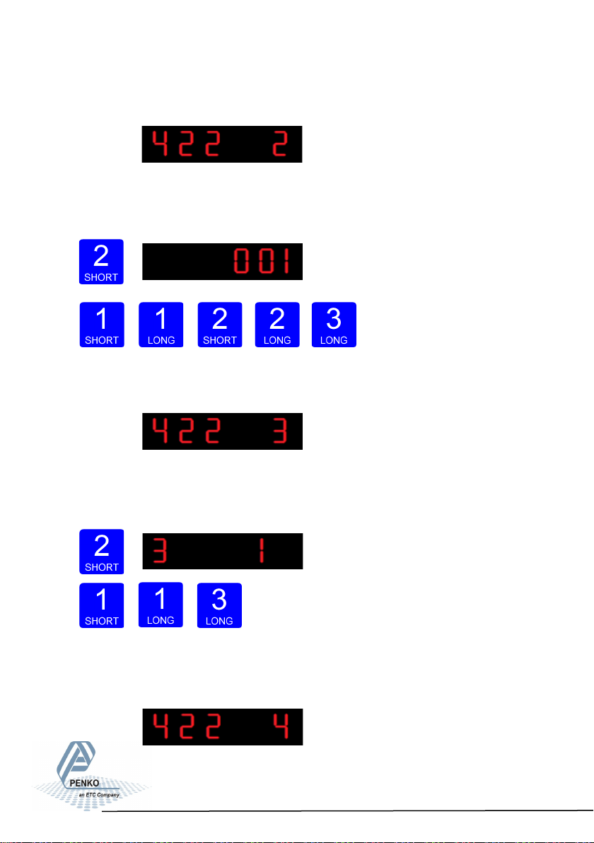
When confirmd the following screen will be vissable:
In 422 2 you set the RS422 address of the SGM850. Press key 2 <2 sec. to enter
422 2 Set the address using key 1 and key 2 confirm by pressing key 3 >2 sec.
(options are: 0-255).
Increase Decrease Left
Right Confirm
When confirmd the following screen will be vissable:
In 422 3 you set the RS422 stopbits of the SGM850. Press key 2 <2 sec. to enter
422 3. Set the number of stopbits the protocol needs by using key 1 and key 2
confirm by pressing key 3 >2 sec. (options are: 1-2).
Increase De- crease Confirm
When confirmd the following screen will be vissable:
58
Page 59
SGM800 Digizer
Conguraon Menu –422- -connue-
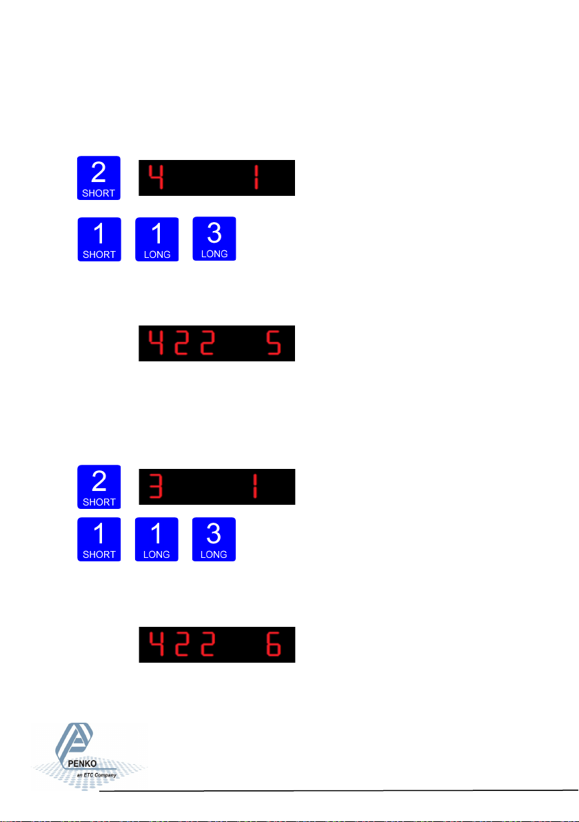
In 422 4 you set the RS422 Parity of the SGM850. Press key 2 <2 sec. to enter
422 4 Set the Parity using key 1 and key 2 confirm by pressing key 3 >2 sec.
(options are: 1= none, 2= odd, 3= even, 4= mark, 5=space).
Increase Decrease Confirm
When confirmd the following screen will be vissable:
In 422 5 you set the RS422 Baudrate of the SGM850. Press key 2 <2 sec. to en-
ter 422 5. Set the speed of the protocol by using key 1 and key 2 confirm by pressing key 3 >2 sec. (options are: 1=1200, 2= 2400, 3= 4800, 4= 9600, 5= 19200,
6= 38400, 7= 57600, 8= 115200 kbps).
Increase Decrease Confirm
When confirmd the following screen will be vissable:
59
Page 60
SGM800 Digizer
Conguraon Menu –422- -connue-
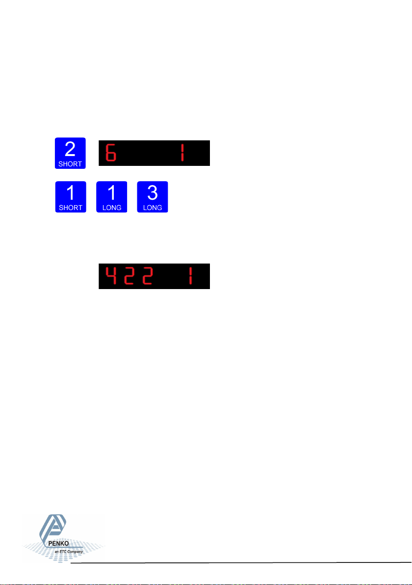
In 422 6 you set the RS422 ASCII Indicator of the SGM850. This setting only ta-
kes effect when using the ASCII protocol. Press key 2 <2 sec. to enter 422 6 Set
the Indicator numer that you want to sent out over the RS424 port by using key 1
and key 2 confirm by pressing key 3 >2 sec. (options are: 1-100).
Increase Decrease Confirm
When confirmd the following screen will be vissable:
60
Page 61
SGM800 Digizer
Conguraon Menu -Ind-
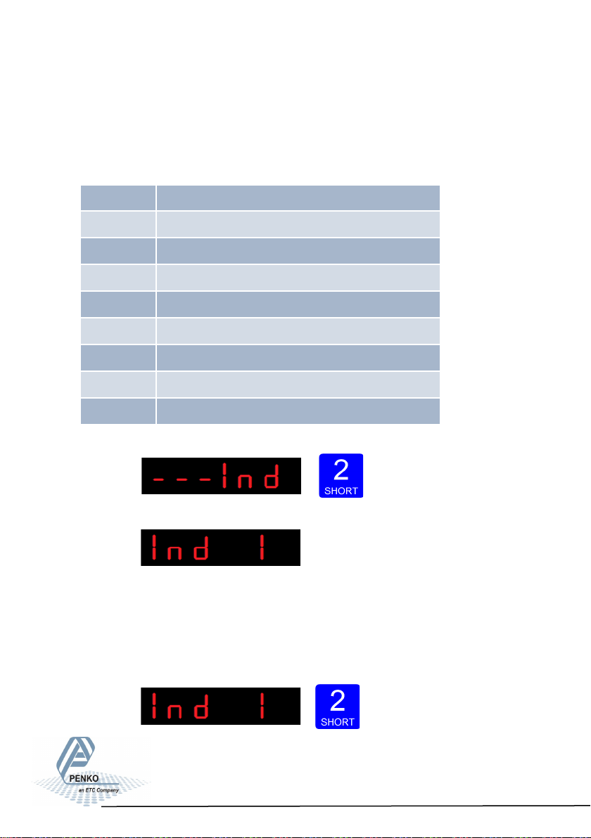
6.10 - - - Ind Indicator settings
In this menu, the Indicator settings can be set.
Options are:
Press key 2 <2 sec to
enter the indicator settings.
The following screen is vissable:
In Ind 1 you set the maximum net weight value. Set maximum load to prevent
overload by the user. The indicator will not show any weight above this value.
Range: 0 – full display.
To change the value press key 2 < 2 sec.
Ind 1 Maximum display value
Ind 2 No moon band
Ind 3 Stable me
Ind 4 Digital overall lter
Ind 5 Display step size
Ind 6 Decimal point posion
Ind 7 Display refreshment speed
Ind 8 Operaon mode
Ind 9 Sample me
61
Page 62
SGM800 Digizer
Conguraon Menu -Ind- -connue-
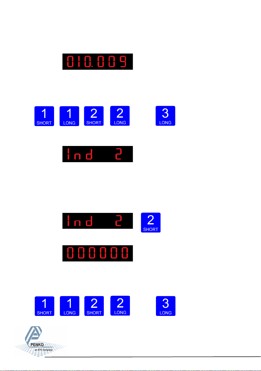
The following screen is vissable:
Use key 1 and 2 to change the value. Key 1 is for changing the number
(1-9), key 2 is for changing the position of the cursor. Confirm by pressing
key 3 for >2 sec.
In- crease Decrease Left
Right Confirm
The following screen is vissable:
In Ind 2 you set the No motion band Indicator gives stable signal when weigher
value is stable within this range and time set with Ind 3.
Choose a value between: 0 – 999999.
To change the value press key 2 < 2 sec.
The following screen is vissable:
Use key 1 and 2 to change the value. Key 1 is for changing the number
(1-9), key 2 is for changing the position of the cursor. Confirm by pressing
key 3 for >2 sec.
In- crease Decrease Left
Right Confirm
62
Page 63
SGM800 Digizer
Conguraon Menu -Ind- -connue-
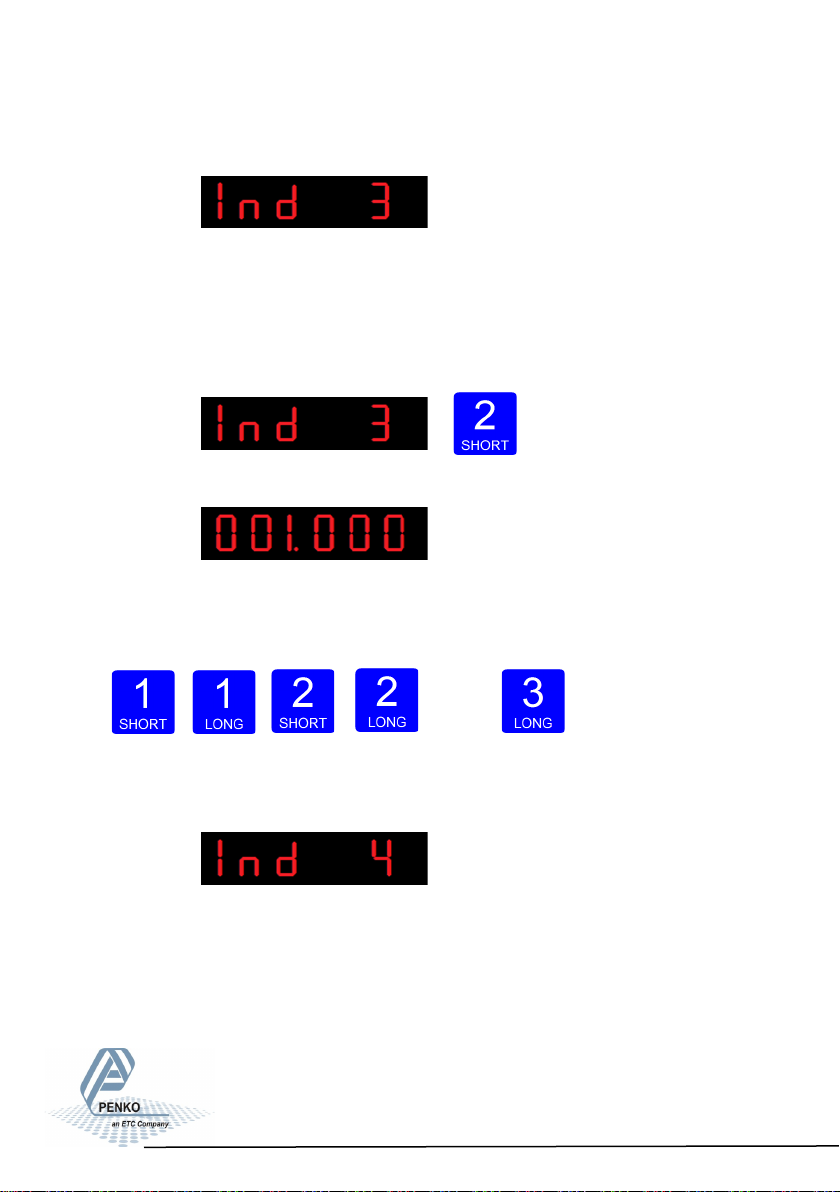
The following screen is vissable:
In Ind 3 you set the Stable time Indicator gives stable signal when weigher value
is stable within the range set in Ind 2 and time set with Ind 3.
Choose a value between: 000.000 – 16.959 seconds.
To change the value press key 2 < 2 sec.
The following screen is vissable:
Use key 1 and 2 to change the value. Key 1 is for
changing the number
(1-9), key 2 is for changing the position of the cursor. Confirm by pressing
key 3 for >2 sec.
In- crease Decrease Left
Right Confirm
The following screen is vissable:
In Ind 4 you set the Digital overall lter. Set the overall filter to effect all indicator
signals used in the device. 0dB means no effect and –50dB is the strongest
damping. Choose between -: 0dB, 1: -6dB, 2: -12dB, 3: -24dB, 4: -30dB,
5: -36dB, 6: -42dB and 7: –50dB.
To prevent a loss of information or accuracy, don’t
set the overall filter higher than 24dB. When no
accuracy is needed, a higher filter setting is allowed
to enable extreme filtering.
63
Page 64
SGM800 Digizer
Conguraon Menu -Ind- -connue-
To change the filter press key 2 < 2 sec.
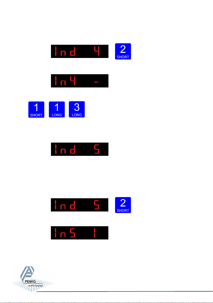
The following screen is vissable:
Use key 1 change the filter. Confirm by pressing key 3 for >2 sec.
Up Down Confirm
The following screen is vissable:
In Ind 5 you set the display step size. The step size
defines the scaled parts of the weight value. The display value will be rounded off
to the nearest value with a valid step size.
To change the display step size press key 2 < 2 sec.
The following screen is vissable:
64
Page 65
SGM800 Digizer
Conguraon Menu -Ind- -connue-
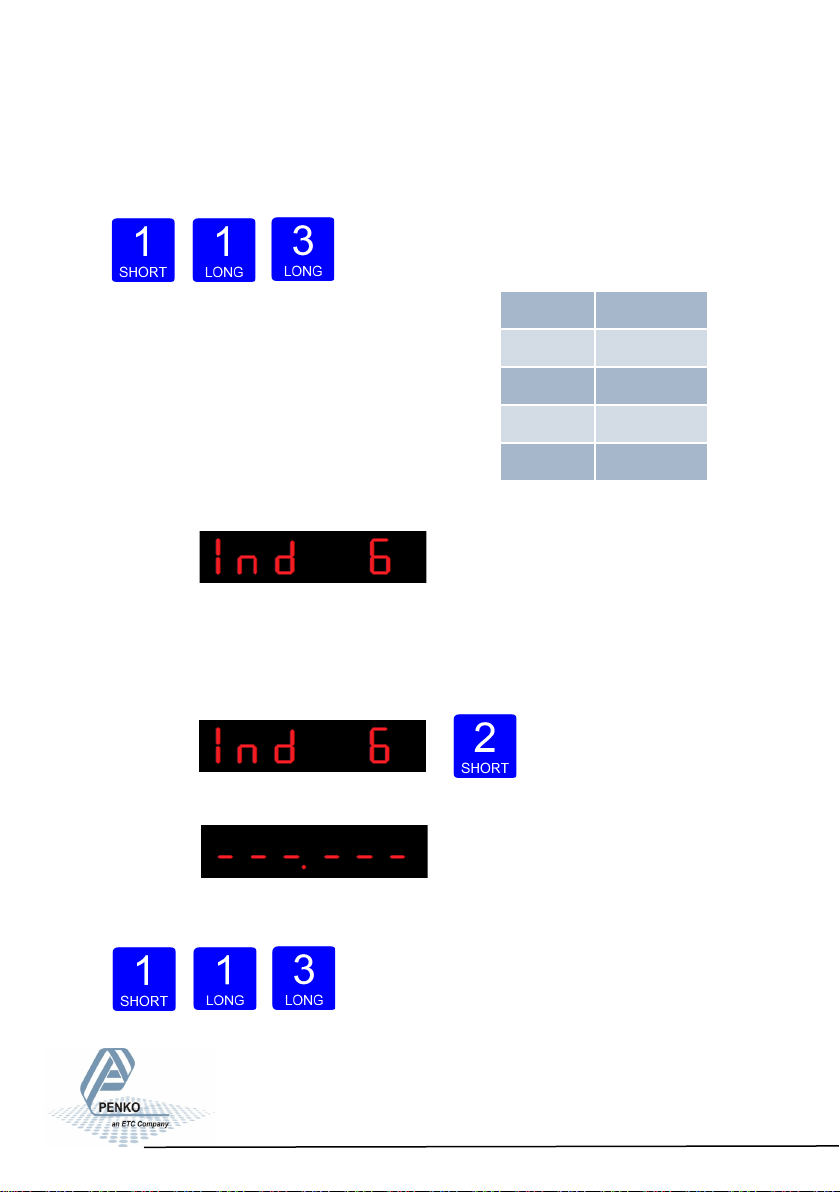
Use key 1 to select the correct step size.
Choose between 1, 2, 5, 10, 20, 50 and confirm by pressing key 3 for >2 sec.
Example step size:
weigher value is 2005 kg
Up Down Confirm
The following screen is vissable:
In Ind 6 you set the decimal point. The decimal point
defines the point position of the weight value.
To change the decimal point press key 2 < 2 sec.
The following screen is vissable:
Press key 1 to define the point position and confirm
by pressing key 3 for >2 sec.
Step Size Weight (kg)
1 2005
2 2006
5 2005
10 2010
Left Right Confirm
65
Page 66
SGM800 Digizer
Conguraon Menu -Ind- -connue-
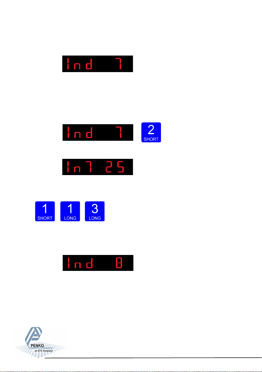
The following screen is vissable:
In Ind 7 you set the Display refreshment speed. The Display refreshment speed
defines the times the weigher value is refresht per second. Options are: 1, 2, 3, 5,
10, 25, 50.
To change the display refreshment speed press key 2 < 2 sec.
The following screen is vissable:
Press key 1 to choose the display refreshment speed
and confirm by pressing key 3 for >2 sec.
The following screen is vissable:
Up Down Confirm
66
Page 67
SGM800 Digizer
Conguraon Menu -Ind- -connue-
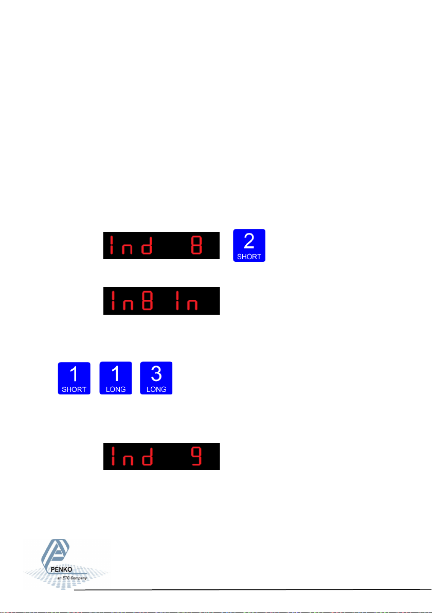
In Ind 8 you set the operation mode of the SGM800. Set the operation mode of
the unit to Industrial or Certified. In Industrial mode it’s always possible to change
the indicator parameters and calibration. In certified mode the unit will be sealed
by marks and also the weighing parameters will be blocked to satisfy to the calibration laws. A weighing unit must be certified when it’s used for measuring for
trade aims. Note: In certified mode the zero band = 4% (+2 and -2%). Also zero
suppressing (FIL 3) is disabled.
Opons are: In = Industrial mode, CE = Cered mode.
To change the operation mode press key 2 < 2 sec.
The following screen is vissable:
Press key 1 to choose the operation mode and con-
firm by pressing key 3 for >2 sec.
Up Down Confirm
The following screen is vissable:
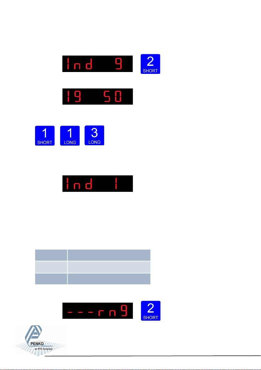
In Ind 9 you set the sample rate of the indicator. The
sample rate is the refreshment speed of the weigher signal.
Options are: 10, 20, 25, 50, 100, 200, 400, 800, 1600 samples/sec.
67
Page 68
SGM800 Digizer
Conguraon Menu -Ind- -connue-
To change the sample rate press key 2 < 2 sec.
The following screen is vissable:
Press key 1 to choose the sample rate and confirm by pressing key 3 for >2 sec.
Up Down Confirm
The following screen is vissable:
Configura- tion Menu -rng-
6.11 - - - rng Multi range/interval settings
In this menu, the multi range/interval can be set.
Options are:
Press key 2 <2 sec to enter the multi
Rng 1 Number of display divisions
Rng 2 Maximum auto range step size
Rng 3 Auto range reset opon
range/interval settings.
68
Page 69
SGM800 Digizer
Conguraon Menu -rng- -connue-
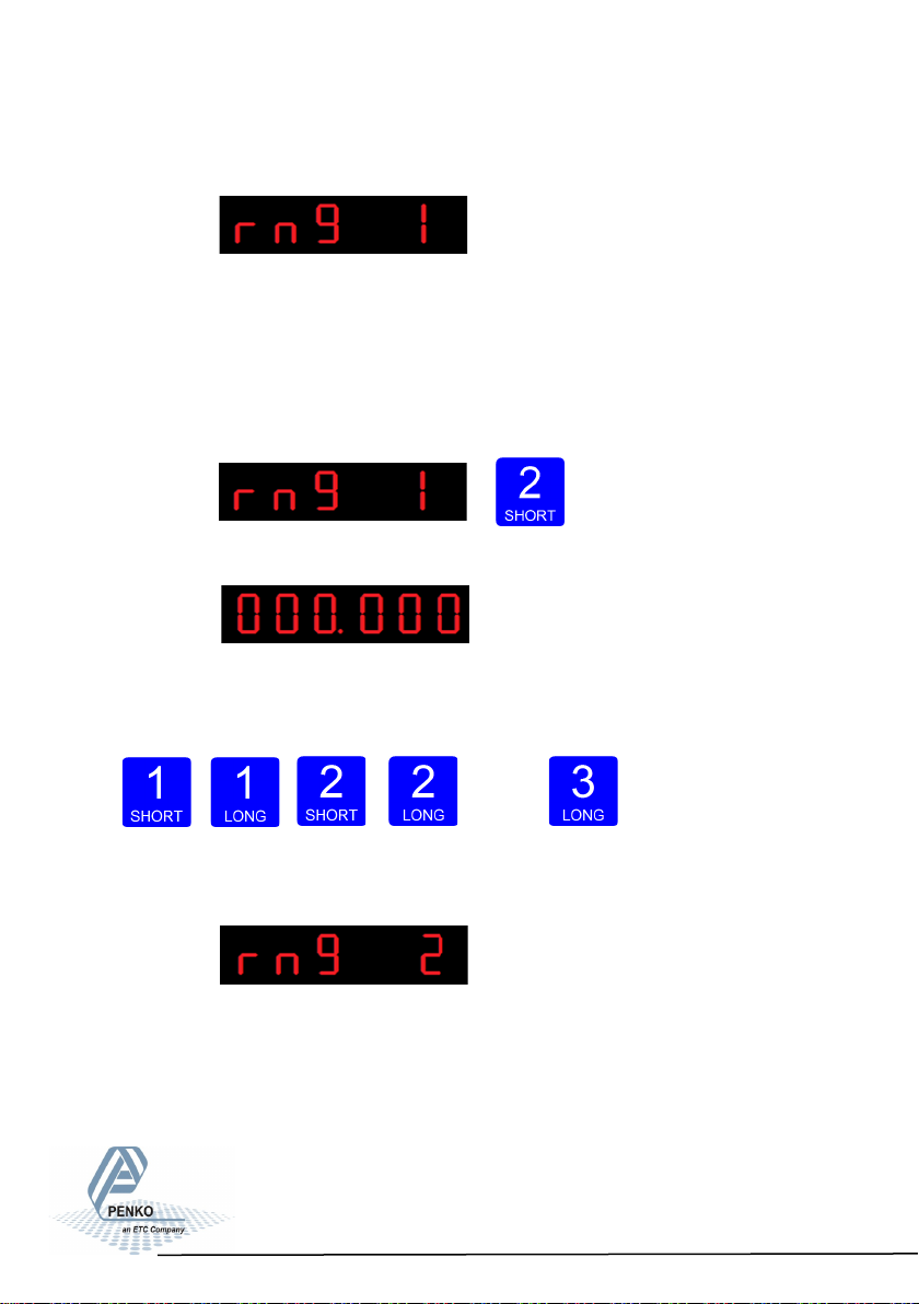
The following screen is visable:
In rng 1 you set the number of display divisions. Set the number of divisions when
the indicator has to display with the next step size. Auto ranging starts with step
size set at Ind 5 and is disabled when range size is set to 0. Choose a value be-
tween 000.00 and 999.999.
To change the value press key 2 < 2 sec.
The following screen is vissable:
Use key 1 and 2 to change the value. Key 1 is for
changing the number
(1-9), key 2 is for changing the position of the cursor. Confirm by pressing
key 3 for >2 sec.
Up Down
Left Right Confirm
The following screen is vissable:
In rng 2 you set the maximum auto range step size. Set the biggest step size al-
lowed. Choose between 1, 2, 5, 10, 20, 50, 100, 200 and 500.
69
Page 70
SGM800 Digizer
Conguraon Menu -rng- -connue-
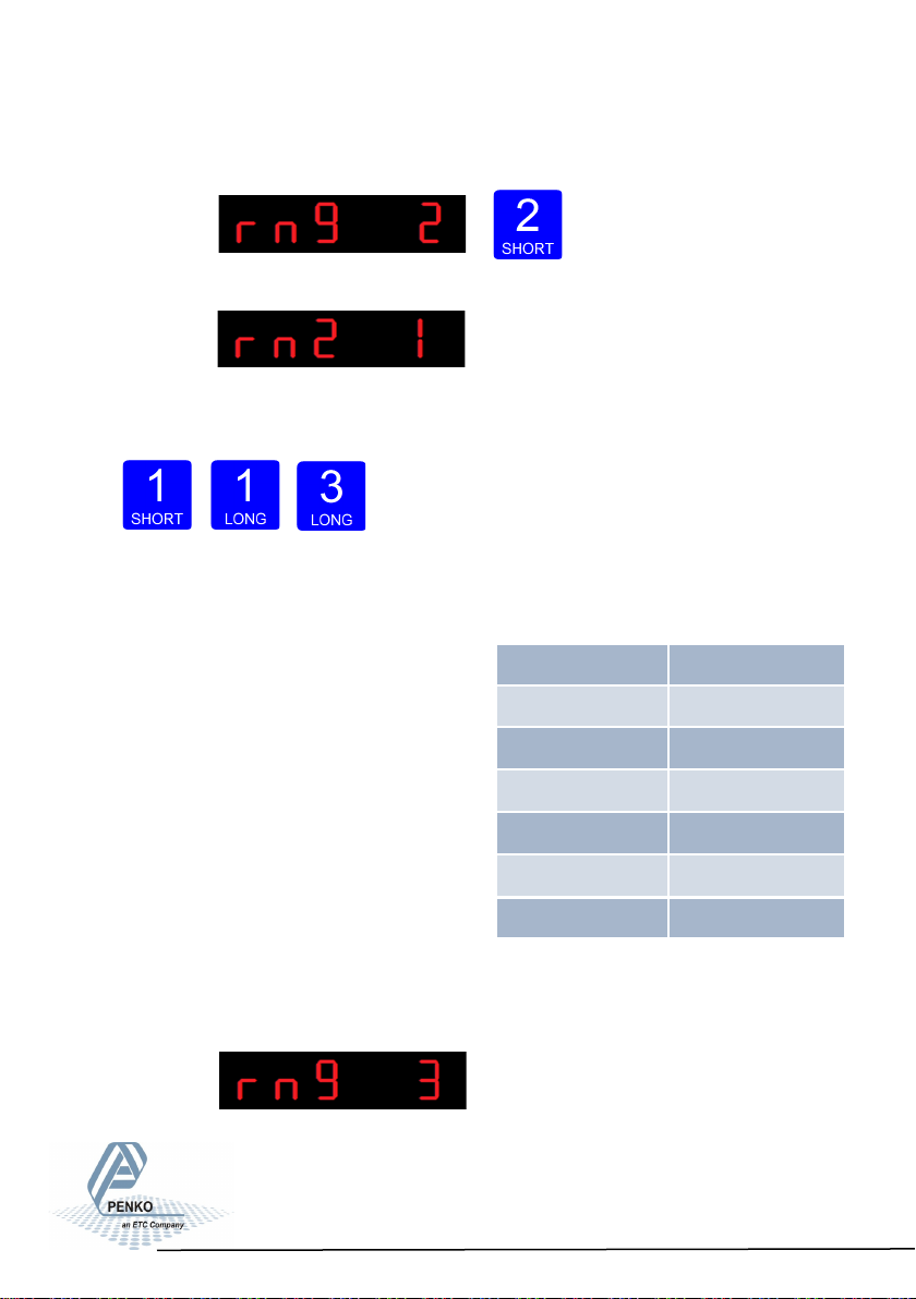
To change the maximum step size press key 2 < 2 sec.
The following screen is vissable:
Use key 1 change the filter. Key 1 is for changing the number.
Confirm by pressing key 3 for >2 sec.
Up Down Confirm
Example Max Step:
If the settings are:
Step size = 1, Range = 100 and Max.
Step = 50, the table on the right shows the
accompanying step size with which the
weigher values reduces within the displayed
ranges.
Displayed range Step size
0-100 1
100-200 2
200-500 5
When the indicator is set certified, the
maximum preset tare is equal to the first
level of the autorange. In this example the
preset tare is valid to 100.
The following screen is vissable:
500-1000 10
1000-2000 20
2000-5000+ 50
70
Page 71
SGM800 Digizer
Conguraon Menu -rng- -connue-
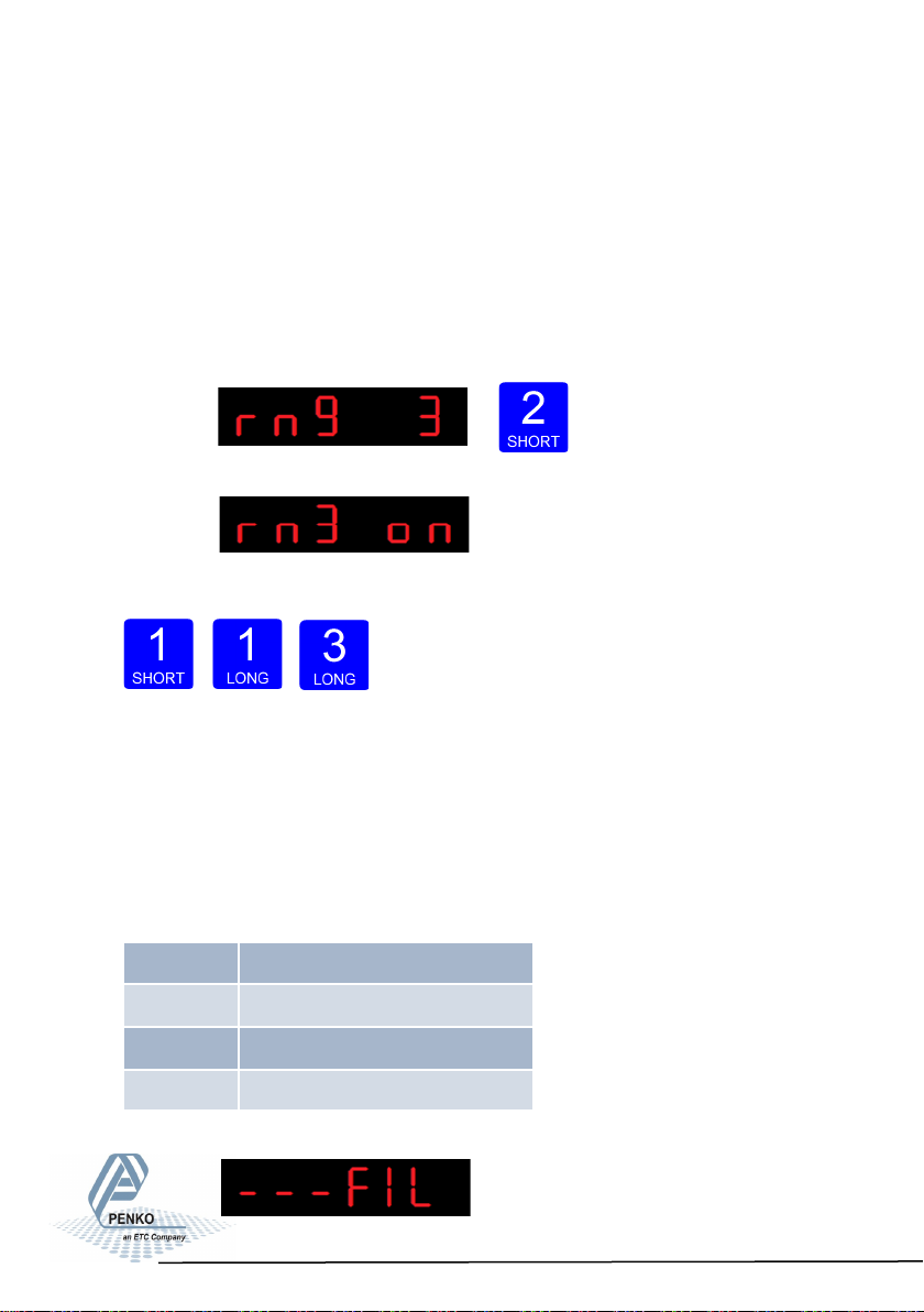
In rng 3 you set the auto range reset option. Choose between:
oF: Multi Range = the highest shown step size will be reseted after the signal has
been lower or equal to zero
on: Mulit Interval = the highest shown step size will be reseted after the signal
reaches the previous range.
To change the auto range reset option press key 2 < 2 sec.
The following screen is vissable:
Use key 1 change the reset option. Confirm by
pressing key 3 for >2 sec.
Up Down Confirm
Configuration Menu -FIL-
6.12 - - FIL Filter settings
In this menu, the filter settings can be set. The display filter will damp the weigher
signal to the display to get a calm display view.
Options are:
Press key 2 <2 sec to enter the filter
settings.
FIL 1 Display lter band
FIL 2 Display lter factor
FIL 3 Zero suppressing
FIL 4 Shown indicator on display
71
Page 72
SGM800 Digizer
Conguraon Menu -FIL- -connue-
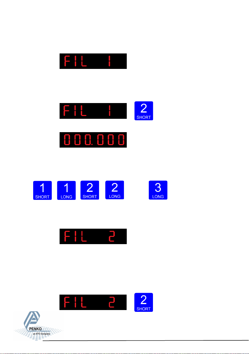
The following screen is visible:
In FIL 1 you can set the display filter band. Set the band where the filter is
active. This parameter works together wit FIL 2. Choose a value between –99999
kg and 999999 kg. Press key 2 <2 sec. to change the filter band.
The following screen is visible:
Use key 1 and 2 to change the value. Key 1 is for
changing the number
(1-9), key 2 is for changing the position of the cursor. Confirm by pressing
key 3 for >2 sec.
Up Down Left Right Con-
firm
The following screen is visible:
In FIL 2 you can set the display filter factor. Set the strength of the filter.
0dB means no effect and –50 is the strongest damping. This parameter works
together wit FIL 1. Choose between -: 0dB, 1: -6dB, 2: -12dB, 3: -18dB, 4: -24dB,
5: -30dB, 6: -36dB, 7: -42dB and 8: -50dB.
Press key 2 <2 sec. to change the filter factor.
72
Page 73
SGM800 Digizer
Conguraon Menu -FIL- -connue-
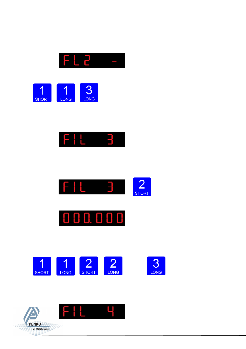
The following screen is visible:
Use key 1 change the filter. Confirm by pressing key 3 for >2 sec.
Up Down Confirm
.
The following screen is visible:
In FIL 3 you set the band within the indicator will show
0. When the indicator is certified, this parameter will be disabled. Choose a value
between 000000 and 999999. Press key 2 <2 sec. to change the zero suppress-
ing band.
The following screen is visible:
Use key 1 and 2 to change the value. Key 1 is for changing the number
(1-9), key 2 is for changing the position of the cursor. Confirm by pressing
key 3 for >2 sec.
Up Down
Left Right Confirm
The following screen is visible:
73
Page 74
SGM800 Digizer
Conguraon Menu -FIL- -connue-
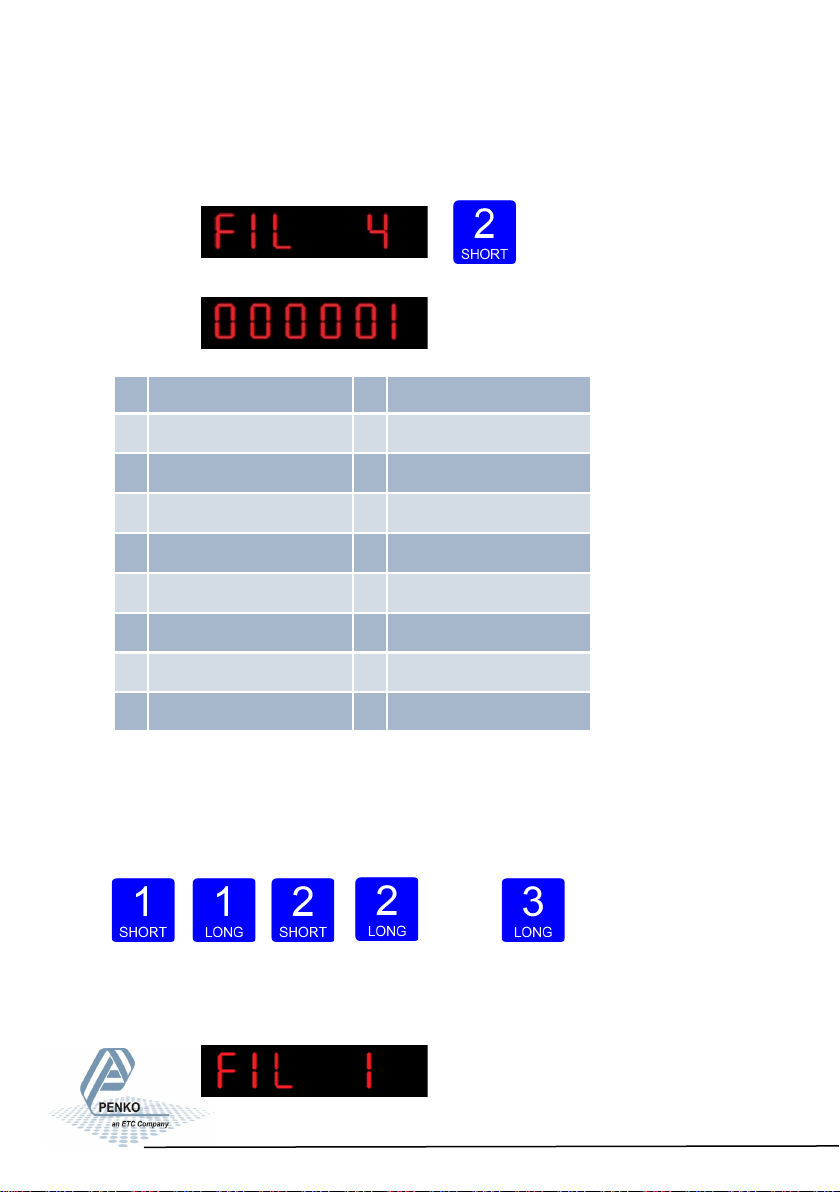
In FIL 4 you can set the number of the indicator shown in the display. Choose a
number between 1 and 17. When using the FIL parameters use 4, 5, 12 or 13.
The following screen is visible:
The options are:
For further detais on
the weigher functions
check appendix I
Use key 1 and 2 to change the value. Key 1 is for changing the number
(1-9), key 2 is for changing the position of the cursor. Confirm by pressing
key 3 for >2 sec.
Up Down Left Right Confirm
The following screen is visible:
1 Weigher 10 Fast gross x 10
2 Fast gross 11 Fast Net x 10
3 Fast net 12 Display Gross x 10
4 Display Gross 13 Display Net x 10
5 Display Net 14 Tare x 10
6 Tare 15 Peak x 10
7 Peak 16 Valley x 10
8 Valley 17 Sample
9 Weigher x 10
74
Page 75
SGM800 Digizer
Conguraon Menu -dSF-
6.13 - - - dSF Digital filter settings
In this menu, the digital filter settings can be set. This filter is a 2nd order filter. The
filter effects all signals up to and including the cutoff frequency. Options are:
Press key 2 <2 sec to enter the
digital filter set- tings.
The following screen is visible:
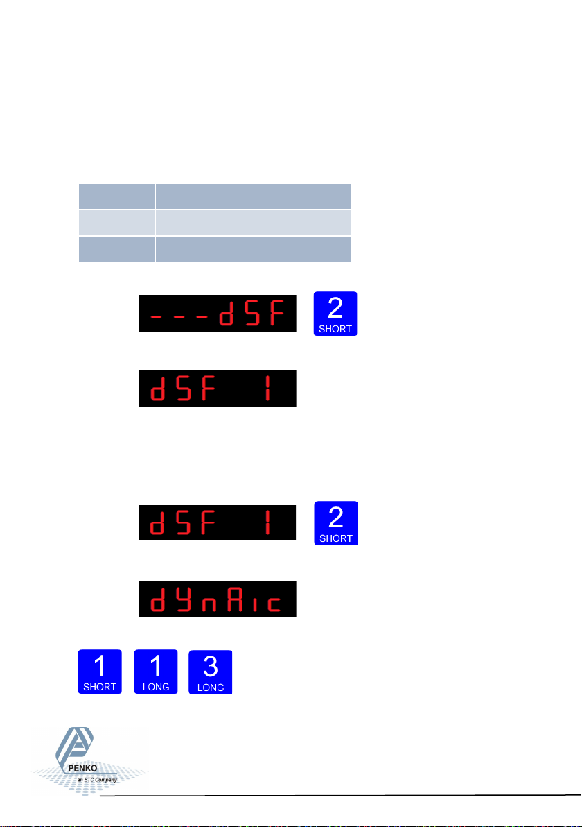
In dSF 1 you can set the filter type.
Choose between None, Dynamic and Static. Dynamic application = used when
the weighing signal is constantly changing. Static application = used when the
weighing signal is stable . Press key 2 <2 sec. to change the filter band.
The following screen is visible:
Use key 1 change the filter type. Confirm by
press- ing key 3 for >2 sec.
Up Down Confirm
dSF 1 Filter type
dSF 2 Cuto frequency
dSF 3 Moving average cuto frequency
75
Page 76
SGM800 Digizer
Conguraon Menu -dSF- -connue-
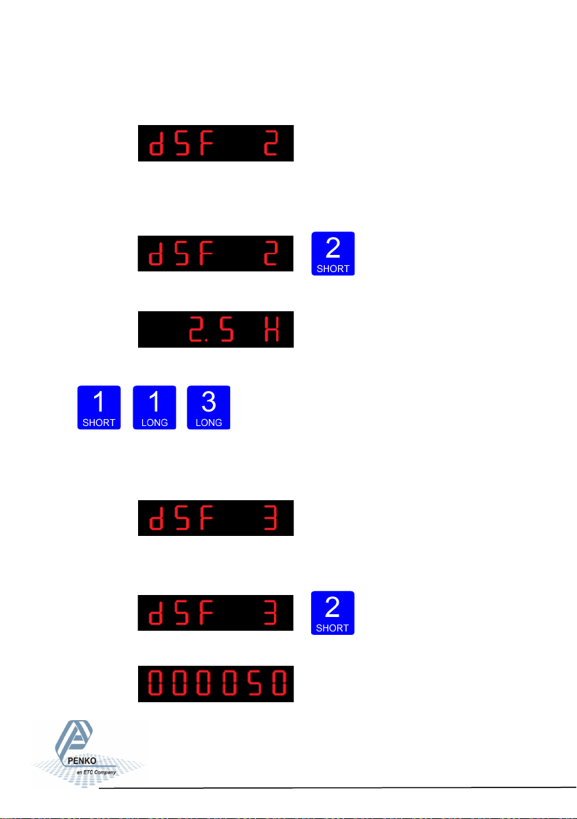
The following screen is visible:
In dSF 2 you can set the Cutoff frequency. Determines the range used for
filtering the signal. Choose between oFF, 1.0Hz, 1.4Hz, 2.5Hz, 5.0Hz, 10.0Hz,
20.0Hz and 40Hz. Press key 2 <2 sec. to change the cutoff frequency range.
The following screen is visible:
Use key 1 change the cutoff frequency. Confirm
by pressing key 3 for >2 sec.
Up Down Confirm
The following screen is visible:
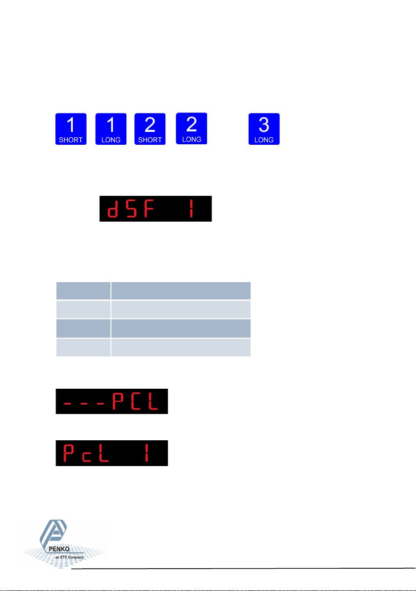
In dSF 3 you can set the moving average cutoff
frequency. Choose a value between 0-320 Hz. Press key 2 <2 sec. to change
the cutoff frequency range.
The following screen is visible:
76
Page 77
SGM800 Digizer
Conguraon Menu -PCL-
Use key 1 and 2 to change the value. Key 1 is for changing the number
(1-9), key 2 is for changing the position of the cursor. Confirm by pressing
key 3 for >2 sec.
Up Down
Left Right Confirm
The following screen is visible:
6.14 - - - PCL Pre-calibration settings
In this menu, the Pre-calibration settings can b e set. Options are:
Press key 2 <2 sec to enter the pre-calibration settings.
The following screen is visible:
Pcl 1 Polarity of input range
PcL 2 Amplier sensivity
PcL 3 Input oset
PcL 4 Recall pre-calibraon
77
Page 78
SGM800 Digizer
Conguraon Menu -PCL- -connue-
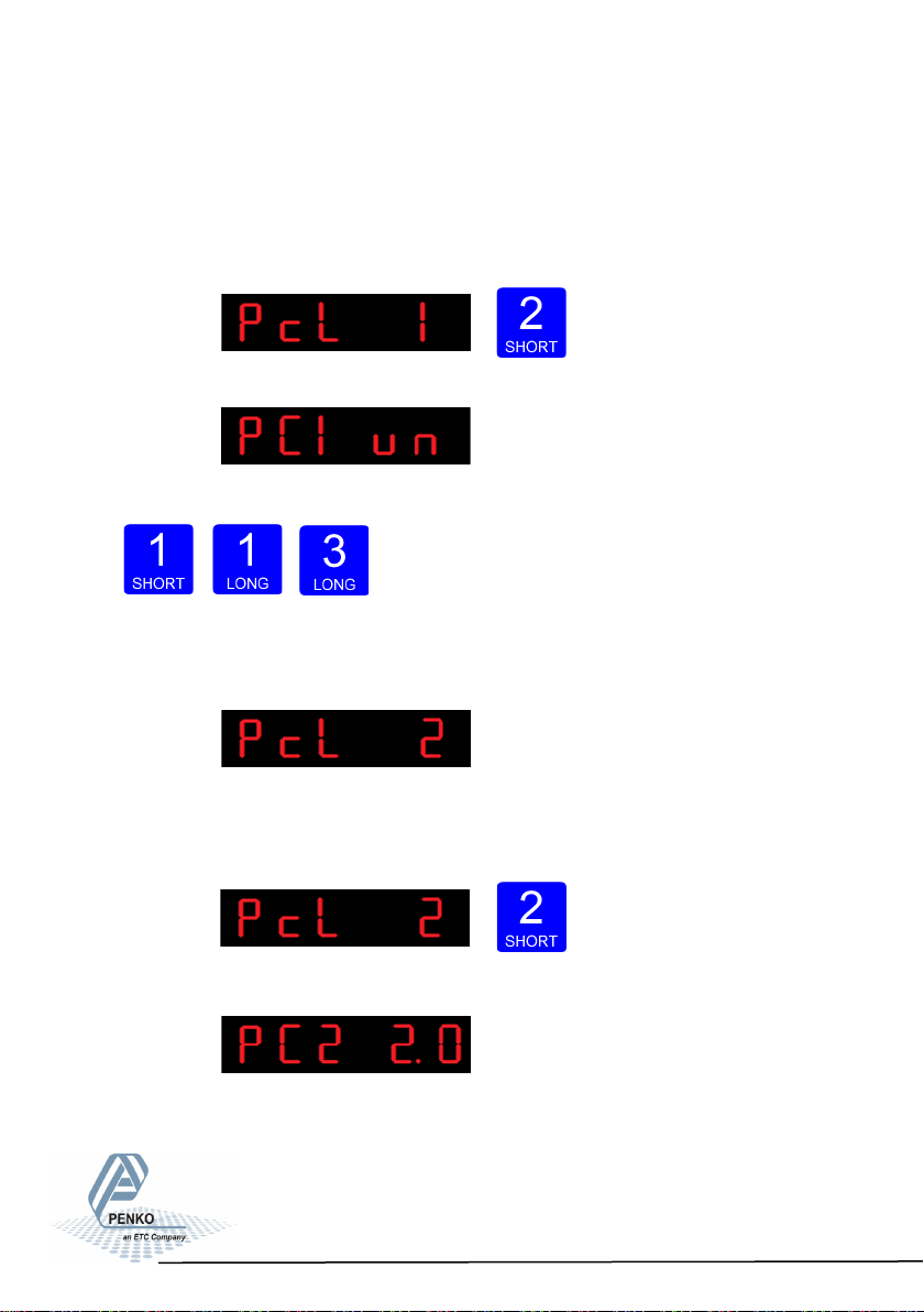
In PcL 1 you can set the polaritiy of the input range. Un=Unipolar mode the input
range for load cells is –0.2 mV/V to + value set at Range. Bi=Bipolar mode the
input range for load cells is –value set at Range to + value set at Range.Press
key 2 <2 sec. To change the polaritity og the input range.
The following screen is visible:
Use key 1 change the polarity. Confirm by pressing key 3 for >2 sec.
Up Down Confirm
The following screen is visible:
In PcL 2 you can set the Amplifier sensitivity.
Choose between 1.0mV/V, 1.5mV/V, 2.0mV/V, 2.5mV/V and 3.0mV/V. Press key
2 <2 sec. to change the amplifier sensitivity.
The following screen is visible:
78
Page 79
SGM800 Digizer
Conguraon Menu -PCL- -connue-
Use key 1 change the sensitiviy. Confirm by pressing key 3 for >2 sec.
Up Down Confirm
The following screen is visible:
In PcL 3 you can set the Input offset. Choose bet-
ween choose a sample value between –50000 and 50000. Press key 2 <2 sec. to
change the in- put offset
The following screen is visible:
Use key 1 and 2 to change the value. Key 1 is for changing the number
(1-9), key 2 is for changing the position of the cursor. Confirm by pressing
key 3 for >2 sec.
Up Down
Left Right Confirm
The following screen is visible:
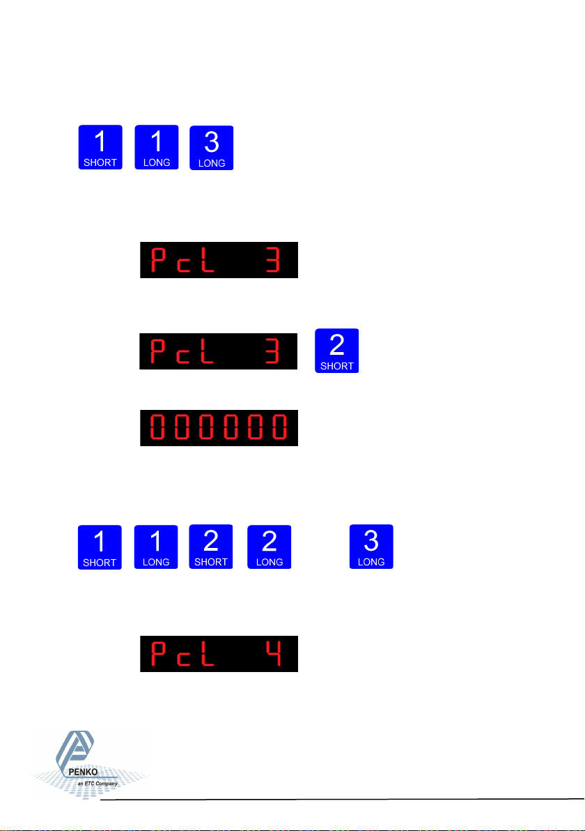
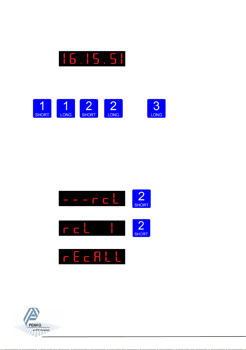
In PcL you can Recall the Pcl parameters.The PcL parameters will be reset to its
factory settings. Press key 2 <2 sec. to recall to factory settings
79
Page 80
SGM800 Digizer
Conguraon Menu -PCL- -connue-
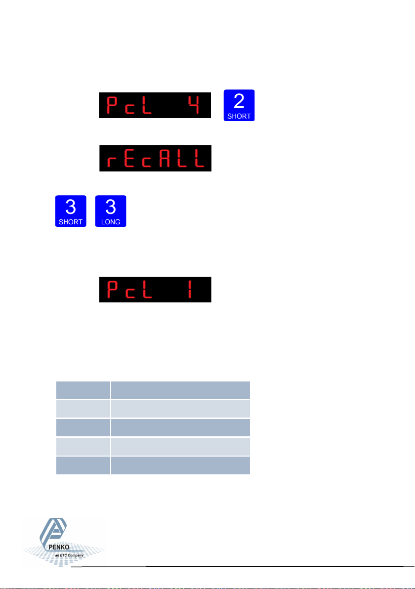
The following screen is visible:
The following screen is visible:
To recall the factory settings press key 3 >2 sec.
To cancel press key 3 <2 sec.
Cancel Recall
The following screen is visible:
Configuration Menu -CAL-
6.15 - - - CAL Calibration settings
In this menu, the Calibration settings can be set. Options are:
CAL 1 Add calibraon point
CAL 2 Check weiger informaon
CAL 3 Show/remove calibraon points
CAL 4 Deadload compensaon
CAL 5 Show CAL code
80
Page 81
SGM800 Digizer
Conguraon Menu -CAL- -connue-
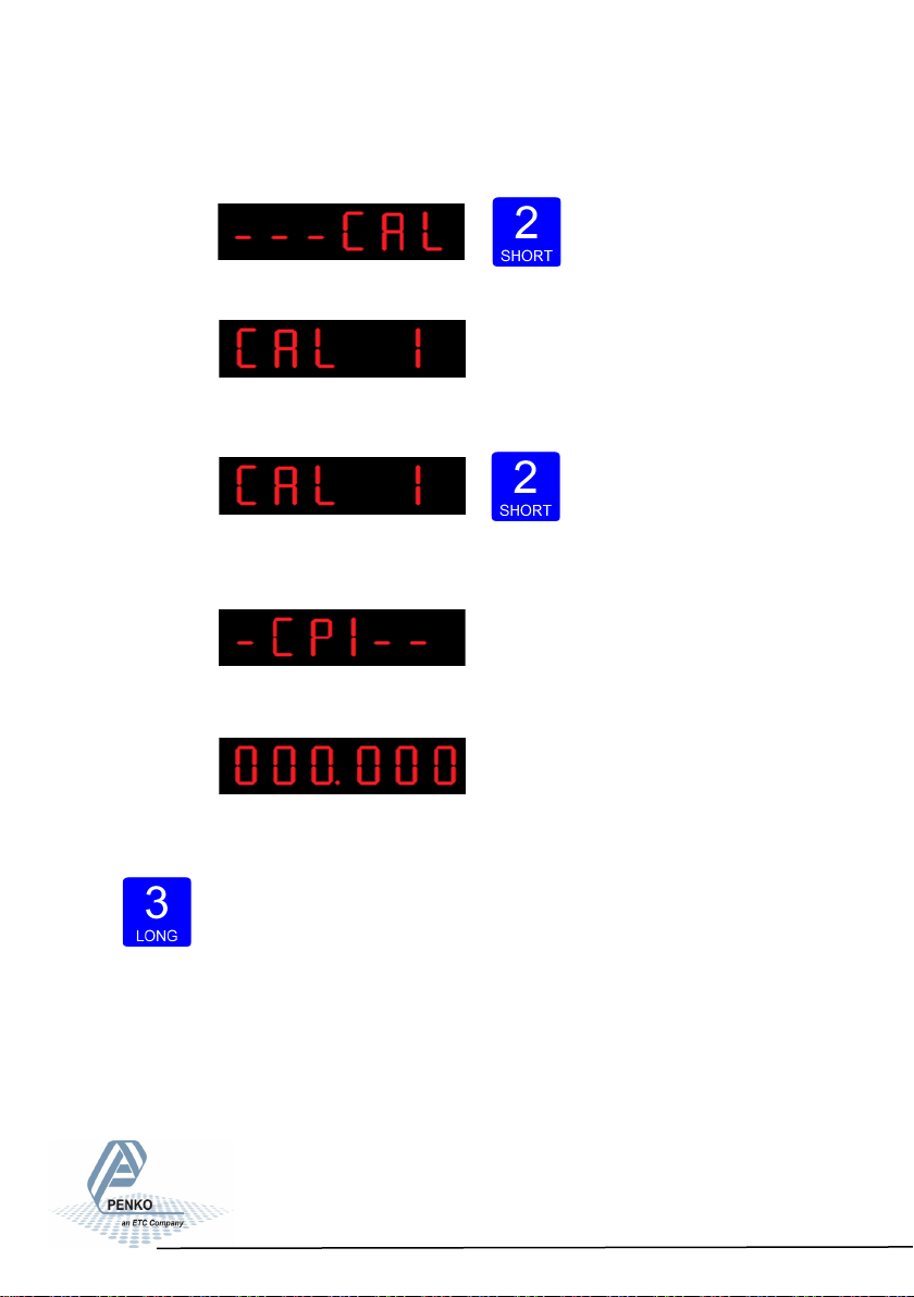
Press key 2 <2 sec to enter the calibration settings.
The following screen is visible:
In CAL 1 you can set the calibration points for the
weigher. Press key 2 <2 sec. to set the calibration points.
After entering, the following screen is visible (if there are no calibration
points available):
And will auto- matically jump to:
First calibrate the zero point (CP1). Make sure the
weigher is unloaded and press key 3 >2 sec.
81
Page 82
SGM800 Digizer
Conguraon Menu -CAL- -connue-
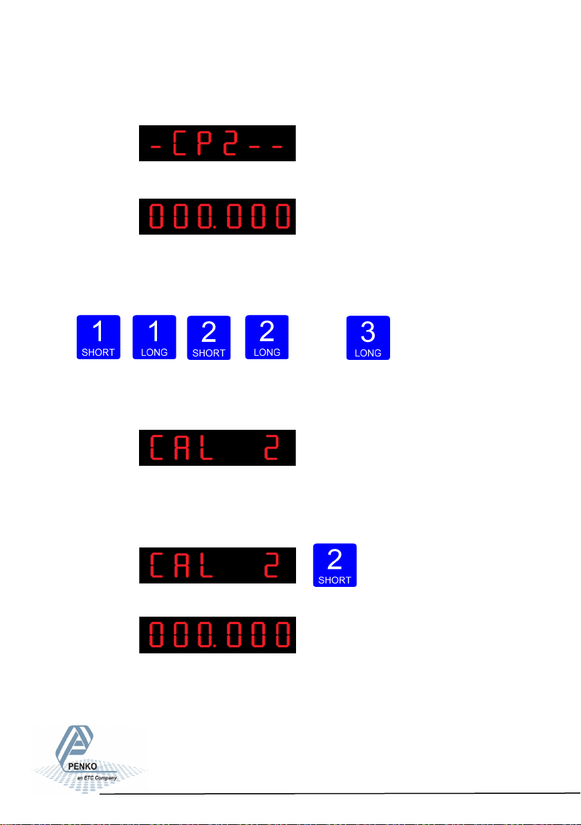
The indicator now shows CP2 to calibrate the gain point (CP2).
And will automatically jump to:
Use key 1 and key 2 to enter the reference value. Key 1 is used for changing the
number (1-9), key 2 is used for changing the position of the cursor. Load the
weigher with the reference value and press key 3 >2 sec.
Up Down
Left Right Confirm
Done succesfully the following screen is visible:
In CAL 2 you can check the weiger information. You can check out the, actual
weigher value, actual weigher value x10 and the actual ADC value.
Press key 2 <2 sec. to check out the weigher information.
The following screen is visible:
82
Page 83
SGM800 Digizer
Conguraon Menu -CAL- -connue-
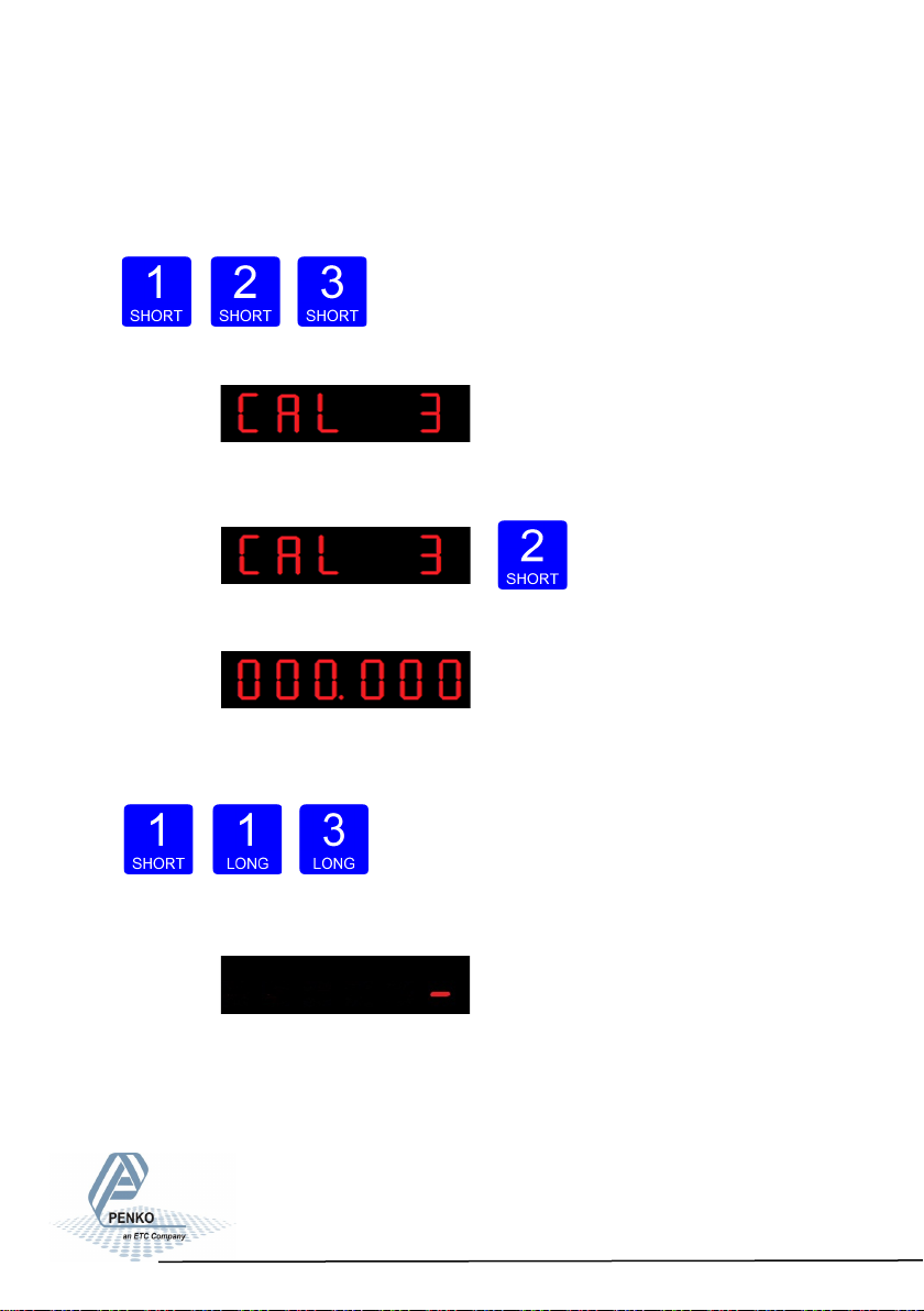
Use key 1 <2 sec. to toggle between the actual weight and the actual weight x10.
Use key 2 <2 sec. to toggle between the actual weight and the ADC value.
When finished press key 3< 2 sec.
The following screen is visible:
Use CAL 3 to check and delete all existing cali-
bration points.
Press key 2 <2 sec. to enter CAL 3.
The following screen is visible:
Step through the calibration points with key 1. Delete a calibration point by
pressing key 3 >3 sec.
Up Down Delete
During deletions, the following screen is visible:
83
Page 84
SGM800 Digizer
Conguraon Menu -CAL- -connue-
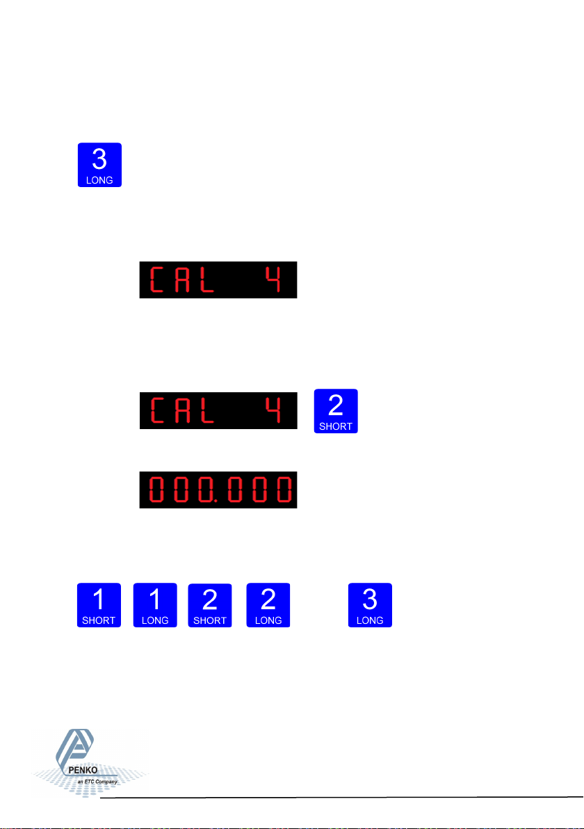
When a number is shown, the deletion of one calibration point is completed and
more points need to be deleted. Press key 3 >3 sec to do so.
>3 sec.
When all calibration points are deleted, the following screen is visible:
In CAL 4 you can set a Deadload compensation. In
this menu, the deadload can be set to pull the whole weighing line back to zero.
The zero point could be different because of some modification on the scale or
dirt. Press key 2 <2 sec. to set a new deadload compensation.
The following screen is visible:
Use key 1 and key 2 to enter the weight that is in/on
the weigher. Key 1 is used for changing the number (1-9), key 2 is used for changing the position of the
cursor. And press key 3 >2 sec.to set the new deadload.
Up Down
Left Right Confirm
84
Page 85
SGM800 Digizer
Conguraon Menu -CAL- -connue-
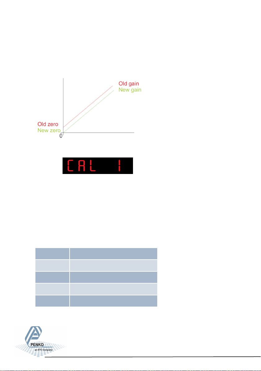
Normally, the deadload is zero, but it is possible to change the line position if
there is weight on the scale. To do so, edit the actual weigh value to the new
known value.
When the new dead load is set the follo-
wing screen is visible:
Configuration Menu -tCL-
6.16 - - - tCL Theoretic calibration
In this menu, the Theoretic calibration settings can be set. Here you can set a
calibration without using a refrence weight. For this you only need the specificati-
on sheets of the used loadcells. Options are:
tCL 1 Maximum load loadcells
tCL 2 Sensivity loadcell 1
tCL 3 Sensivity loadcell 2
tCL 4 Sensivity loadcell 3
tCL 5 Sensivity loadcell 4
85
Page 86
SGM800 Digizer
Conguraon Menu -tCL- -connue-
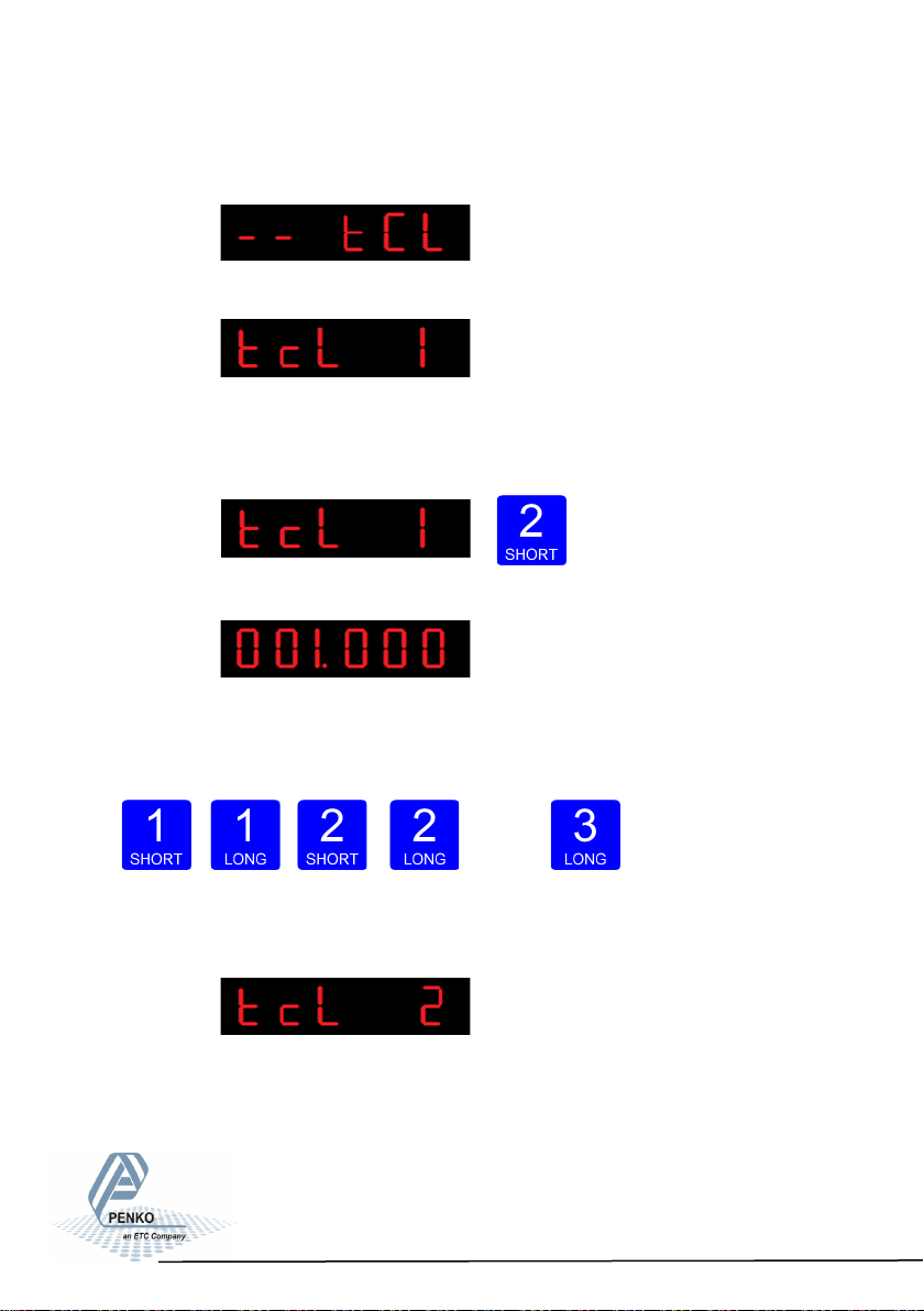
Press key 2 <2 sec to enter the theoreatic calibration settings.
The following screen is visible:
In tcL 1 you can set the maximum loadcell load. When more then one loadcell is
used all loadcells should have the same maximum load. Press key 2 <2 sec. to
set the maximum load.
The following screen is visible:
Use key 1 and key 2 to enter the maximum load of
the loadcell(s). Key 1 is used for changing the number (1-9), key 2 is used for
changing the position of the
cursor. And press key 3 >2 sec.to set the maximum load.
Up Down
Left Right Confirm
The following screen is visible:
In tcL 2 you can set the loadcell sensitivity for loadcell 1. This information can be
found on the datasheet deliverd with the loadcell. Press key 2 <2 sec. to set the
loadcell sensitivity.
86
Page 87
SGM800 Digizer
Conguraon Menu -tCL- -connue-
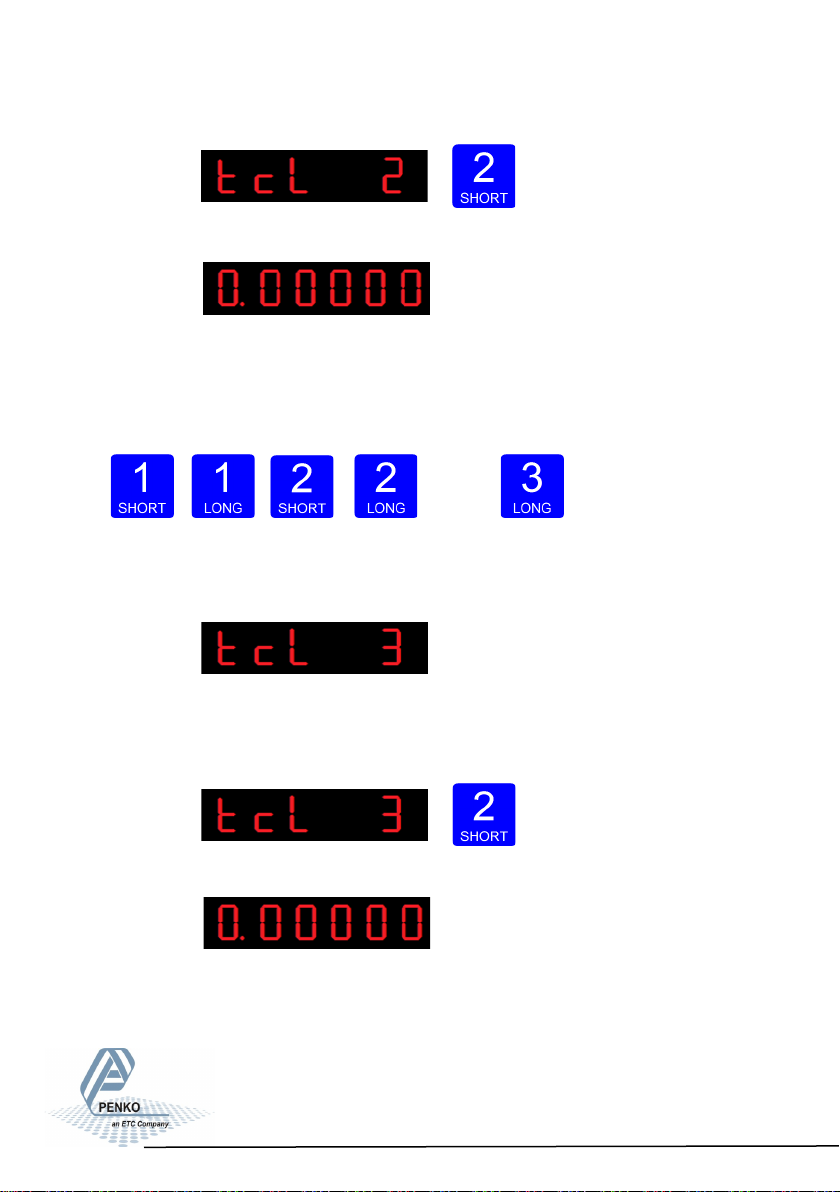
The following screen is visible:
Use key 1 and key 2 to enter the sensitivitiy of loadcell 1. Key 1 is used for
changing the number (1-9), key 2 is used for changing the position of the
cursor. Sensitivity has to be filled in as 0.00000 mV/V. Press key 3 >2 sec. to set
the sensitivity of the loadcell.
Up Down
Left Right Confirm
The following screen is visible:
In tcL 3 you can set the loadcell sensitivity for loadcell 2. This information can be
found on the datasheet deliverd with the loadcell. Press key 2 <2 sec. to set the
loadcell sensitivity.
The following screen is visible:
87
Page 88
SGM800 Digizer
Conguraon Menu -tCL- -connue-
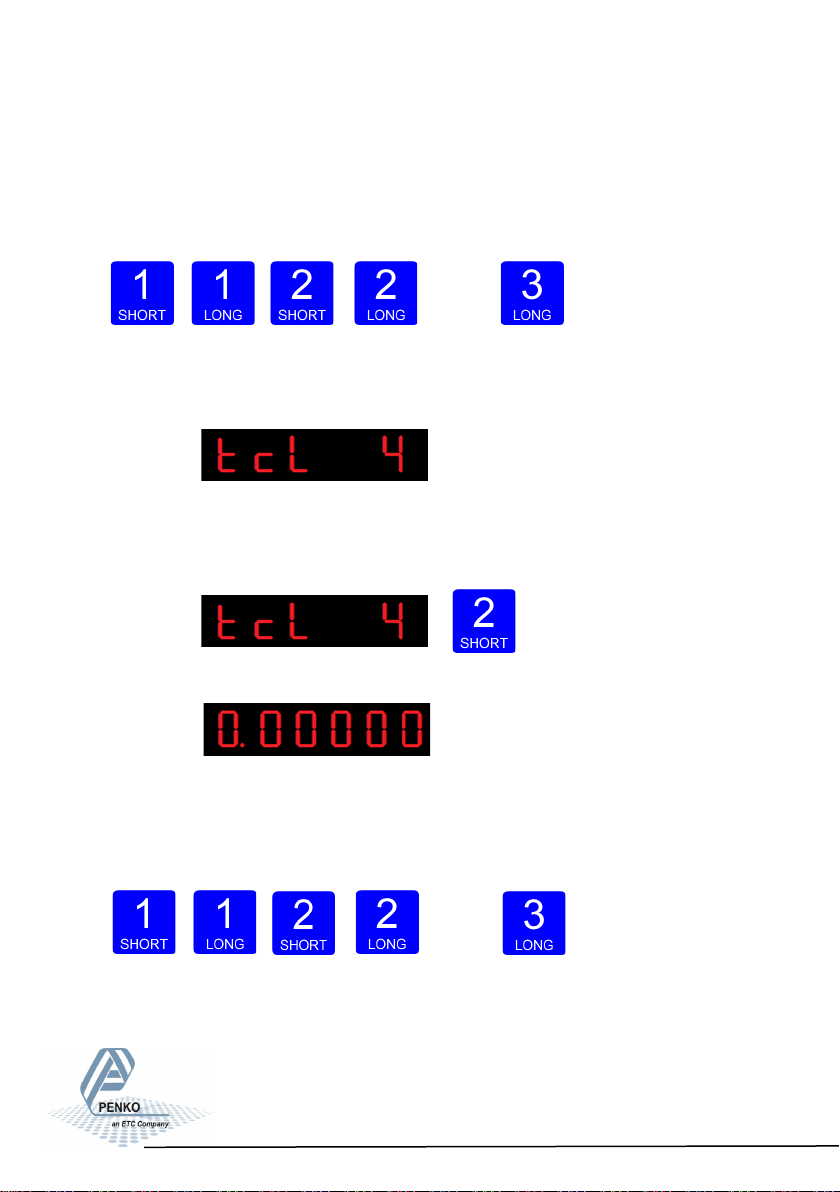
Use key 1 and key 2 to enter the sensitivitiy of loadcell 2. Key 1 is used for
changing the number (1-9), key 2 is used for changing the position of the
cursor. Sensitivity has to be filled in as 0.00000 mV/V. Press key 3 >2 sec. to set
the sensitivity of the loadcell.
Up Down
Left Right Confirm
The following screen is visible:
In tcL 4 you can set the loadcell sensitivity for loadcell 3. This information can be
found on the datasheet deliverd with the loadcell. Press key 2 <2 sec. to set the
loadcell sensitivity.
The following screen is visible:
Use key 1 and key 2 to enter the sensitivitiy of loadcell 3. Key 1 is used for
changing the number (1-9), key 2 is used for changing the position of the
cursor. Sensitivity has to be filled in as 0.00000 mV/V. Press key 3 >2 sec. to set
the sensitivity of the loadcell.
Up Down
Left Right Confirm
88
Page 89
SGM800 Digizer
Conguraon Menu -tCL- -connue-
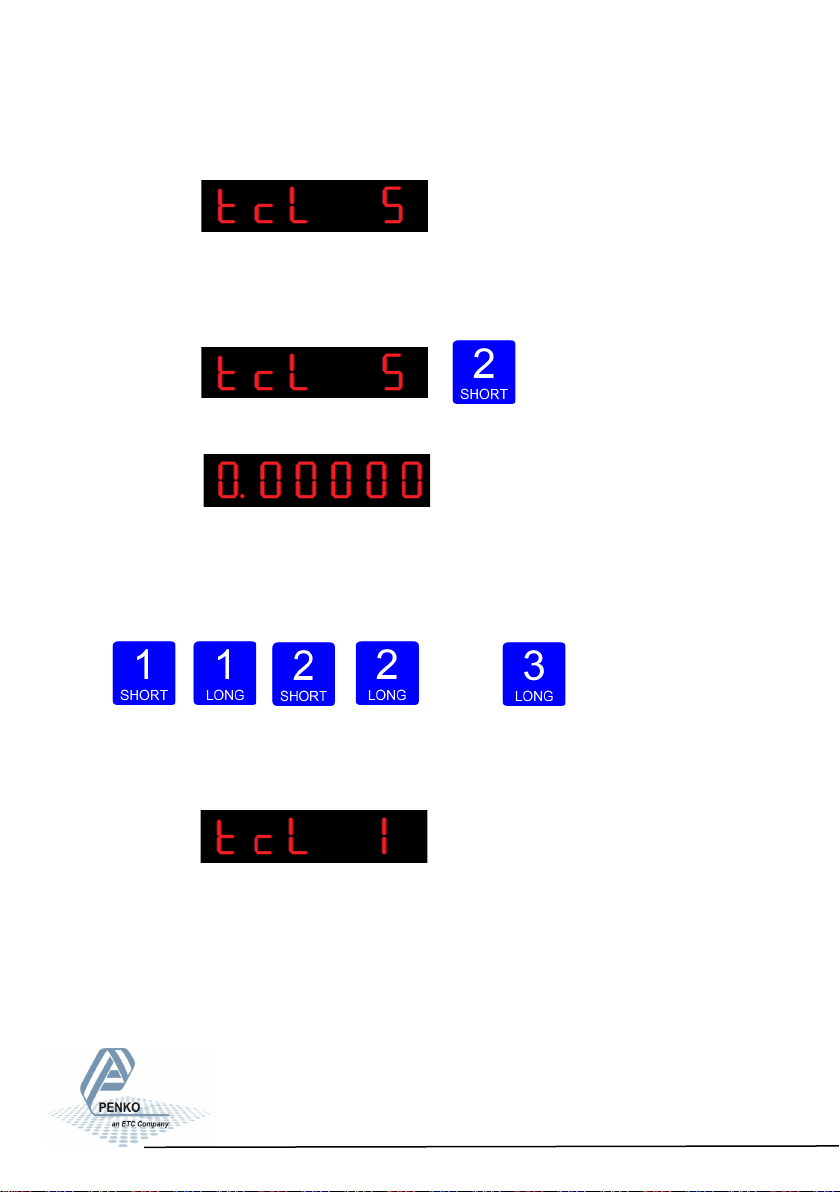
The following screen is visible:
In tcL 5 you can set the loadcell sensitivity for loadcell 4. This information can be
found on the datasheet deliverd with the loadcell. Press key 2 <2 sec. to set the
loadcell sensitivity.
The following screen is visible:
Use key 1 and key 2 to enter the sensitivitiy of load-
cell 4. Key 1 is used for
changing the number (1-9), key 2 is used for changing the position of the
cursor. Sensitivity has to be filled in as 0.00000 mV/V. Press key 3 >2 sec. to set
the sensitivity of the loadcell.
Up Down Left Right Confirm
The following screen is visible:
When using a theoretical calibration, note that the
2mV/V and 3mV/V range are calibrated ranges.
89
Page 90
SGM800 Digizer
Conguraon Menu -gCL-
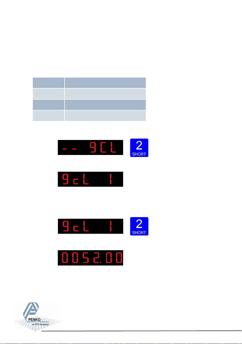
6.17 - - - gCL Geographic calibration
In this menu, the Geographic calibration settings can be set. Here you can set a
geographic information of the loadcells filled in al tCL. Options are:
Press key 2 <2 sec to enter the Geographic calibration settings.
The following screen is visible:
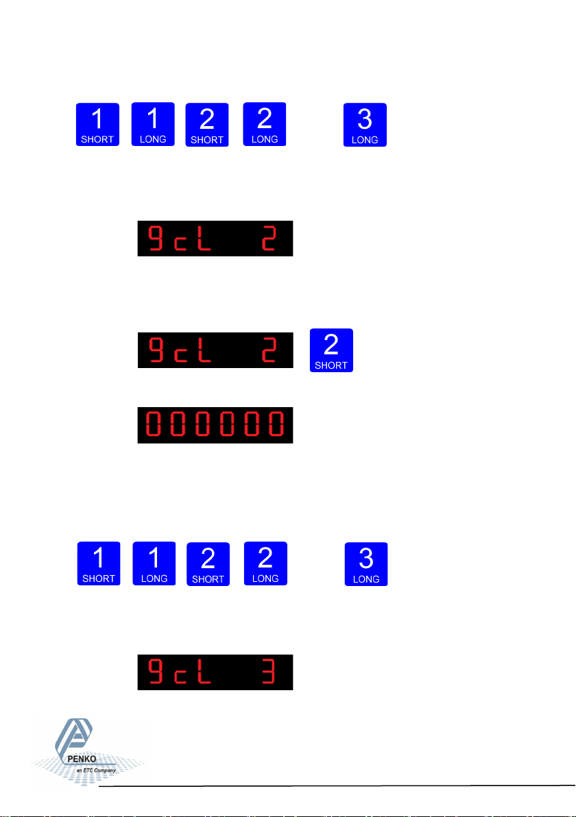
In gcL 1 you can set the origin latitude of the load-
cell. This is the geographic latitude of where the loadcell is manufactured. Press
key 2 <2 sec. to set the origin latitude.
The following screen is visible:
Use key 1 and key 2 to enter the origin latitide of the
loadcell(s). Key 1 is used for changing the number (1-
9), key 2 is used for changing the position of the
cursor. And press key 3 >2 sec.to set the origin latitude. Choose value
gCL 1 Origin latude
gCL 2 Origin elevaon
gCL 3 Locaon latude
gCL 4 Locaon elevaon
between –90,00 and 90,00°
90
Page 91
SGM800 Digizer
Conguraon Menu -gCL- -connue-
Up Down Left Right Confirm
The following screen is visible:
In gcL 2 you can set the origin elevation of the
loadcell. This is the geographic elevation of where the loadcell is manufactured.
Press key 2 <2 sec. to set the origin elevation.
The following screen is visible:
Use key 1 and key 2 to enter the origin elavation of
the loadcell(s). Key 1 is used for changing the number (1-9), key 2 is used for
changing the position of the
cursor. And press key 3 >2 sec.to set the origin elevation. Choose value
between –1000 and 30000 meter.
Up Down
Left Right Confirm
The following screen is visible:
91
Page 92
SGM800 Digizer
Conguraon Menu -gCL- -connue-
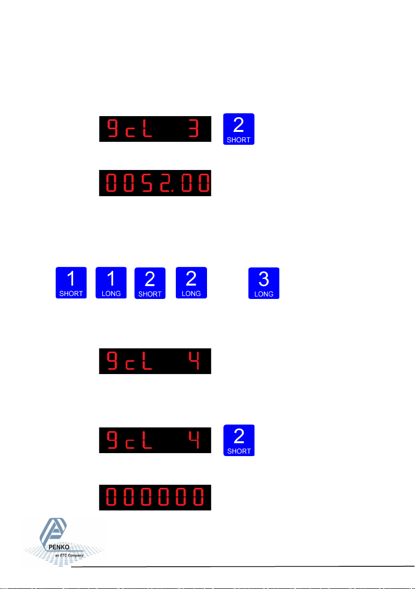
In gcL 3 you can set the location latiude of the loadcell(s). This is the
geographic latitude of where the loadcell is going to be used. Press key 2 <2 sec.
to set the location latitude.
The following screen is visible:
Use key 1 and key 2 to enter the location latitude of
the loadcell(s). Key 1 is used for changing the number (1-9), key 2 is used for
changing the position of the
cursor. And press key 3 >2 sec.to set the location latitude. Choose value
be- tween –
Up Down Left Right Confirm
The following screen is visible:
In gcL 4 you can set the location elevation of the loadcell. This is the
geographic elevation of where the loadcell is going to be used. Press key 2 <2
sec. to set the location elevation.
The following screen is visible:
90,00 and 90,00°
92
Page 93
SGM800 Digizer
Conguraon Menu -gCL- -connue-
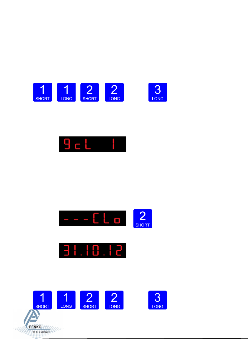
Use key 1 and key 2 to enter the location elevation of the loadcell(s). Key 1 is
used for changing the number (1-9), key 2 is used for changing the position of the
cursor. And press key 3 >2 sec.to set the location latitude. Choose value
between –1000 and 30000 meter.
Up Down Left Right Confirm
The following screen is visible:
Configura- tion Menu –CLo-
6.18 - - - CLo Date and time configuration
In Clock, you can set the internal date and time.
Press key 2 <2 sec to enter Clock.
The following screen is visible:
Set the date. Use key 1 and key 2 to change the
number Key 1 is for changing the number (1-9), key 2 is for changing the position
of the cursor. Confirm by pressing key 3 >2 sec. Format DD.MM.YY
Up Down
Left Right
Confirm
93
Page 94
SGM800 Digizer
Conguraon Menu -CLo- -connue-
The following screen is visible:
Set the time. Use key 1 and key 2 to change the number Key 1 is for changing
the number (1-9), key 2 is for changing the position of the cursor. Confirm by
pressing key 3 >2 sec. Format HH.MM.SS
Up Down
Left Right Confirm
Configuration Menu -rcl-
6.19 - - - rcL Recall
In Recall, you can reset all parameters back to facatory settings.
Press key 2 <2 sec to enter Recall.
The following screen is visible. Press key 2 <2 sec.
The following screen is visible.
There are two recalls available. Parameters back to
factory, or an erase of the file system. Use the erase function only when a normal
recall does not solve the problem.
94
Page 95
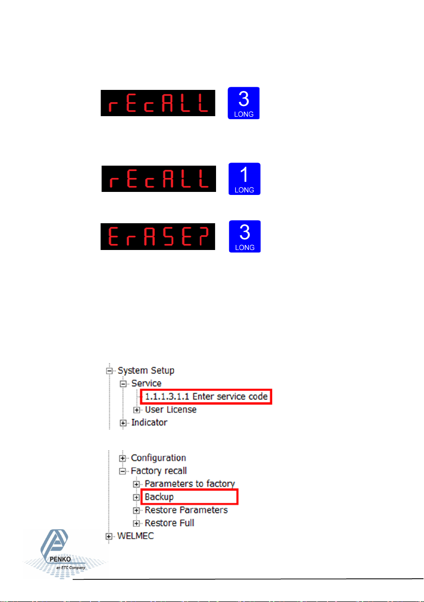
SGM800 Digizer
Conguraon Menu -rcl- -connue-
To set all parameters back to factory settings Press key 3 >2 sec
The device will reboot.
To reset the file system Press key 1 >2 sec.
The following screen is visible. Confirm by pressing key 3 >2 sec.
The device will reboot.
Starting at firmware version 1.6.0.9.0.3 a backup of the device configuration can
be made within the device. A password is required for the backup.
Contact PENKO for this password.
The backup can only be made using Pi Mach II manage. Enter the password in
the service code field.
The backup can be made in the Factory
Recall menu.
95
Page 96
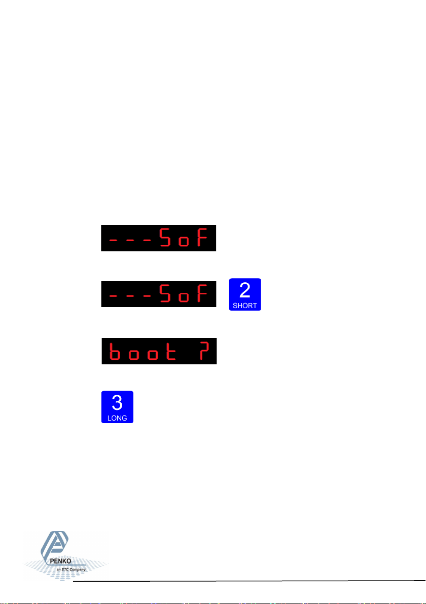
SGM800 Digizer
Conguraon Menu -rcl- -connue-
Restore Parameters only restor es the non -certified parameters. This option is
also available in the device menu, RCL menu, option RCL 2.
Restore Full rest ores all p arameters . Th is option is also av ailable in the de-
vice menu, RCL menu, option RCL 3.
The device restarts after a restore action.
Configuration Menu -SoF-
6.20 - - - SoF Firmware update
In SoF, you can set the SGM800 in boot mode for software update.
Press key 2 <2 sec to enter Boot mode.
The following screen is visible:
Press key 3 >2 sec to set the SGM800 in Boot mode.
96
Page 97
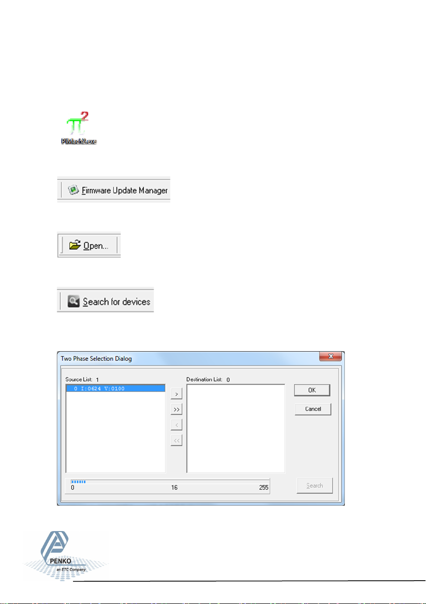
SGM800 Digizer
7. Firmware update
Connect the SGM to the computer through USB. Start PI Mach II. Set communi-
cation to USB.
Start the Firmware Update Manager.
Click Open and select the PIP file.
Click Search For Devices and select the device with source “0”.
Use double click or the arrow button to put the address
in the Destination List and click OK.
97
Page 98
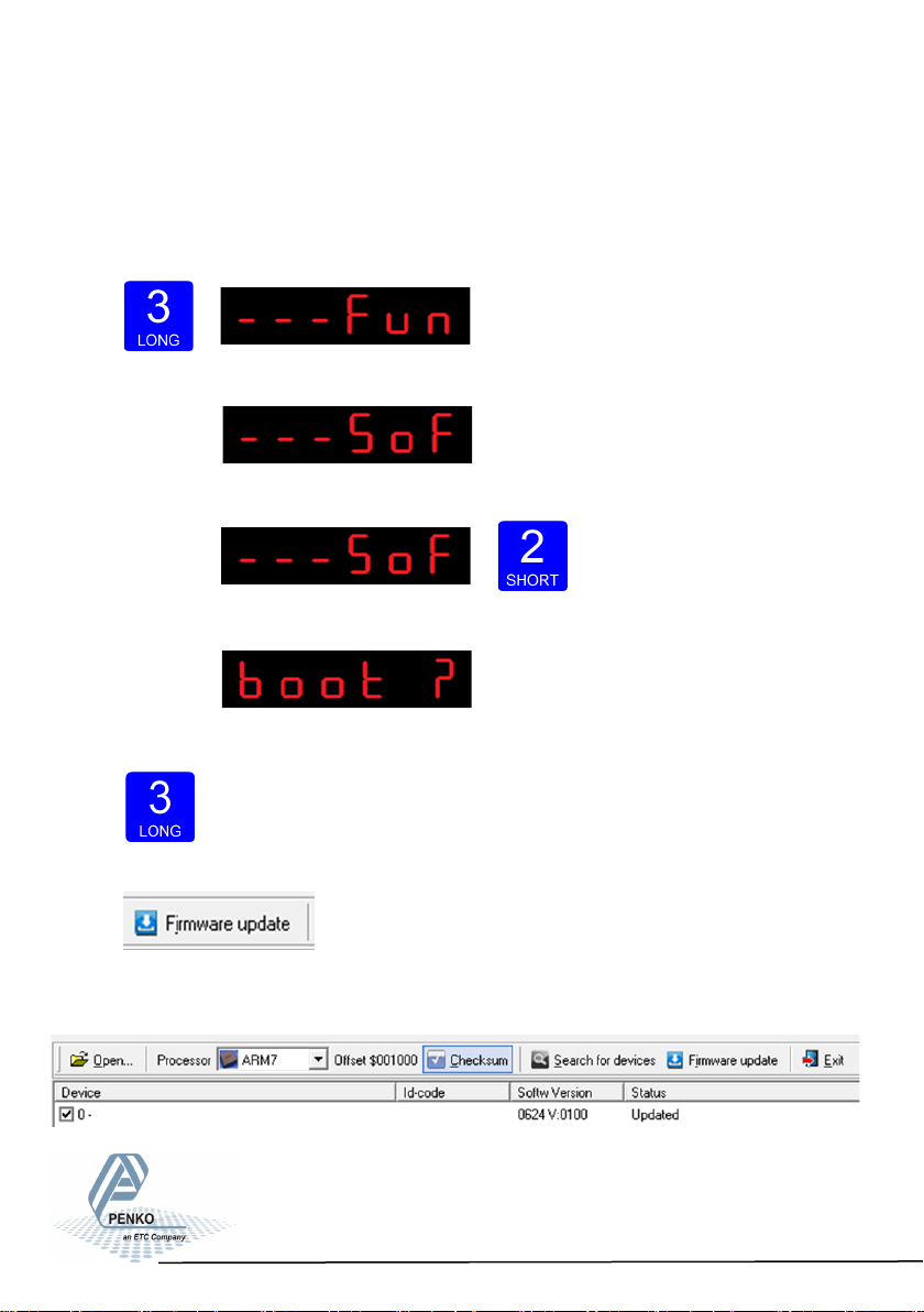
SGM800 Digizer
Firmware update -connue-
Now set the SGM in boot mode:
Go into the configuration menu by pressing key 3 >2 sec.
The following screen will appear:
Go to- - - SoF by pressing key 1 <2 sec un tll yo u see - - - SoF
Press key 2 <2 sec to enter Boot mode.
The following screen is visible:
Press key 3 >2 sec to set the SGM800 in Boot mode.
Now click Firmware Update to start the update.
The SGM will reboot automatically and the Firmware Up-
date Manager wil show Updated.
98
Page 99
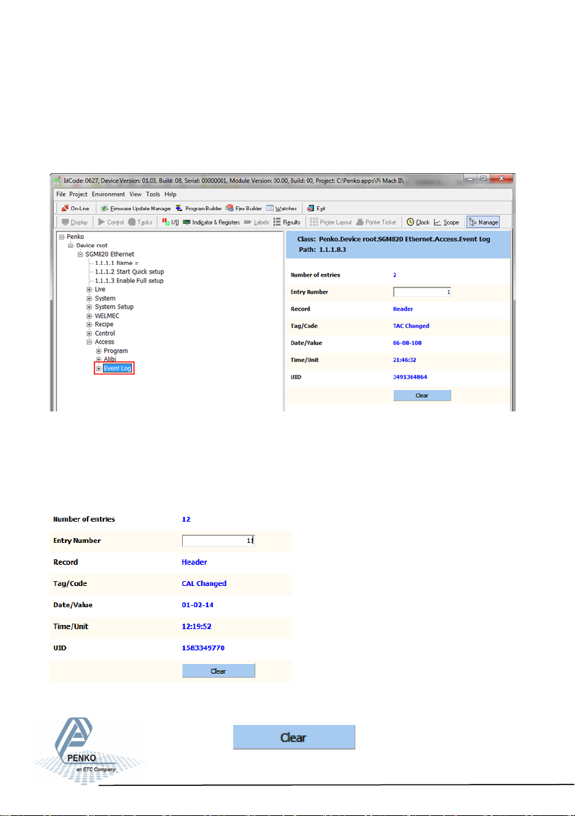
SGM800 Digizer
8. Event Log
Event Log automatically records various system events like Software Updates
and Calibrations.
Event Logs can be viewed via Pi Mach II Manage:
How you can connect your SGM800 to PI Mach II Manage is explained in chapter
4.4 of this manual. Enter the Event number at “Entry Number” and confirm with
Enter or the Apply button. The event is shown.
In this example you can see that Entry 11 is a Calibration change on Februari 1st
2014 at 12:19:52 and it gest the Unique Identification Code (UID) 1583349770.
Events can only be printed with the
SGM850 Serial.
Pressing the button will erase the
complete Event log memory.
99
Page 100
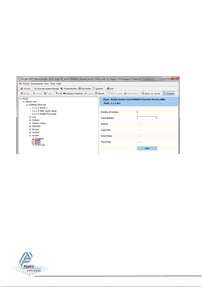
SGM800 Digizer
9. Alibi Memory
The SGM800 has a Alibi Memory function inside. This saves information about
Dosed weight of the SGM800 MFL, checked weight of the SGM800 CHK and
actual weigher value of the SGM800 Indicator. In the SGM800 Belt the Alibi
Memory has no function.
The Alibi memory can be viewed via Pi Mach II Manage:
How you can connect your SGM800 to PI Mach II Manage is explained in chapter
4.4 of this manual.
Events can only be printed with the SGM850 Serial.
100
 Loading...