

Page 1
PENKO Engineering BV
The Leading Experts In Weighing & Dosing
Manual
SGM700
Digitizer
For more information visit
www.penko.com - technical support - literature library
Page 2

SGM700 Digitizer
IMPORTANT SAFETY INFORMATION
READ THIS PAGE FIRST!
Penko Engineering manufactures and tests
its products to meet all applicable naonal
and internaonal standards. It is vital that
this instrument is correctly installed, used,
and maintained to ensure it connues to
operate to its opmum specicaon.
The following instrucons must be adhered
to and incorporated into your safety
program when installing, using, and
maintaining Penko products. Failure to
follow the recommended instrucons can
aect the system’s safety and may increase
the risk of serious personal injury, property
damage, damage to this instrument and
may invalidate the product’s warranty.
• Read the instrucons fully prior to
installing, operang, or servicing the
product. If this Instrucon Manual is not the
correct manual for the Penko product you
are using, call 0031(0)318-525630 for a
replacement copy. Keep this Instrucon
Manual in a safe place for future reference.
• If you do not fully understand these
instrucons, contact your Penko
representave for claricaon.
• Pay careful aenon to all warnings,
cauons, and instrucons marked on and
supplied with the product.
• Inform and educate your personnel about
the correct installaon, operaon, and
maintenance procedures for this product.
• Install your equipment as specied in the
installaon instrucons of the appropriate
Instrucon Manual and as per applicable
local and naonal codes. Connect all
products to the proper electrical sources.
• To ensure correct performance, use quali-
ed personnel to install, operate, update,
program, and maintain the product.
• When replacement parts are required,
ensure that qualied technicians use repla-
cement parts specied by Penko. Unauthori-
zed components and procedures can aect
the product's performance and may aect
the connued safe operaon of your
processes. The use of non-specied ‘look-
alike’ substuon parts may result in the
risk of re, electrical hazards, or improper
operaon.
• Ensure that all equipment doors are closed
and protecve covers are in place, except
when maintenance is being performed by
qualied persons, to prevent electrical
shock and personal injury.
2
Page 3

SGM700 Digitizer
WARNING
ELECTRICAL SHOCK HAZARD
Installing cable connecons and servicing this instrument require access to shock hazard
level voltages which can cause death or serious injury.
Disconnect separate or external power sources to relay contacts before commencing any
maintenance.
The electrical installaon must be carried out in accordance with CE direcons and/or any
other applicable naonal or local codes.
Unused cable conduit entries must be securely sealed by non-ammable blanking plates or
blind grommets to ensure complete enclosure integrity in compliance with personal safety
and environmental protecon requirements.
To ensure safety and correct performance this instrument must be connected to a
properly grounded, three-wire power source.
Proper relay use and conguraon is the responsibility of the user.
Do not operate this instrument without the front cover being secured. Refer any
installaon, operaon or servicing issues to qualied personnel.
WWW.PENKO.COM
Penko is an ETC Company
e-mail: [email protected]
3
Page 4

SGM700 Digitizer
TABLE OF CONTENT
Chapter Page
1.Indication of display
2. Explanation of front keys
3. Loadcell power conection
3.1 SGM700 basic digitizer
3.2 SGM710 digitizer analog
3.3 SGM720 digitizer Ethernet
3.4 SGM730 digitizer CAN
3.5 SGM740 digitizer Profibus
3.6 SGM750 digitizer Serial
4. First use of Indicator
4.1. Weigher Setting
4.2. Calibration
5. Main Menu
5.1 Setpoints
5.2 TAC (Traceable Acces Code)
5.2 CAL (Calibration conter)
6. Configuration Menu
6.1 Setpoint function settings
6.2 Setpoint action settings
6.3 Analog output settings
6.4 Local bus communication settings
6.5 Profibus settings (SGM740 only)
6.6 Ethernet serrings (SGM720 only)
6.7 Indicator settings
6.8 Multi range/interval settings
6.9 Filter settings
6.10 Digital filter settings
6.11 Pre-calibration settings
6.12 Calibration settings
6.13 Theoretic calibration
6.14 Geographic calibration
6.15 Date and time configuration (SGM750 only)
6.16 Recall
6
7
8
8
9
10
11
12
13
14
14
17
20
20
21
22
23
24
25
26
30
31
33
39
46
49
52
54
57
62
67
70
71
4
Page 5

SGM700 Digitizer
TABLE OF CONTENT
Chapter Page
6.17 Firmware update
7. Firmware update
8. Error codes
8.1 Weigher error codes
9. ASCII
9.1 ASCII protocol format
9.2 ASCII protocol commands
10. Profibus protocol description
11. Standard factory settings
Appendix I
72
73
75
76
76
76
77
79
80
83
5
Page 6
SGM700 Digitizer
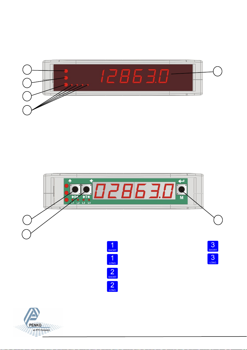
1. Indication of Display
With cover closed
1
2
3
4
1. Weigher stable
2. Zero active
3. Tare active
4. Output active 1-4
5. Weigher value
5
With cover opened
1
2
3
1. key 1 press <2sec.=
key 1 press >2sec.=
2. key 2 press <2sec.=
key 2 press >2sec.=
Functions of these keys will be described on the next page.
3. key 2 press <2sec.=
key 2 press >2sec.=
6
Page 7

SGM700 Digitizer
2. Explanation of front keys
All keys have different functions depending if you are in weighing or
menu mode.
Pressing key 1 “short”.
In Weighing mode: create a new zero level.
In Menu mode: increase value by 1 or move up in menu.
Pressing key 1 “long”.
In Weighing mode: reset zero level to the original zero level.
In Menu mode: decrease value by 1 or move down in menu.
Pressing key 2 “short”.
In Weighing mode: set/ reset tare and reset preset tare.
In Menu mode: go into sub-menu or move cursor 1 position to the left.
Pressing key 2 “long”.
In Weighing mode: set preset tare.
In Menu mode: move cursor 1 position to the right.
Pressing key 3 “short”.
In Weighing mode: enter menu.
In Menu mode: escape move back in menu without saving changes.
Pressing key 3 “long”.
In Weighing mode: enter configuration menu.
In Menu mode: Confirm made changes.
Menu will jump back one level every 30 seconds of inactivity.
7
Page 8

SGM700 Digitizer
3. Load cell / power connection
3.1 SGM700 basic digitizer
DC POWER
SUPPLY
18-32Vdc
6-Wire load cell
connection
Vexc=5Vdc
Inputs
Input 1=5khz
18-28Vdc
Outputs
25V/0.5A
Analoge
output
AC/DC
Local bus
To PC
Config
software
8
Page 9

SGM700 Digitizer
3. Load cell / power connection
3.2 SGM710 digitizer analog
DC POWER
SUPPLY
18-32Vdc
6-Wire load cell
connection
Vexc=5Vdc
To PC
Config
Analoge
output
Local bus
software
9
Page 10
SGM700 Digitizer
3. Load cell / power connection
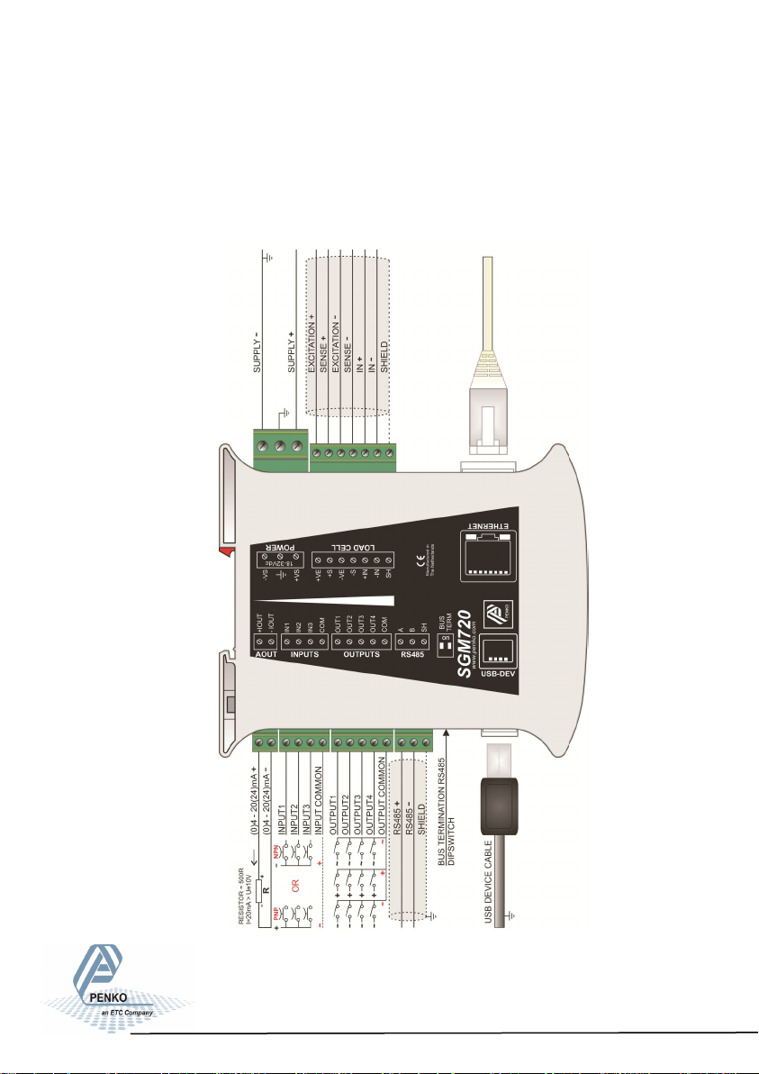
3.3 SGM720 digitizer ethernet
DC POWER
SUPPLY
18-32Vdc
6-Wire load cell
connection
Vexc=5Vdc
Analoge
output
Inputs
Input 1=5khz
18-28Vdc
Outputs
Local bus
25V/0.5A
AC/DC
To PC
Config
software
10
Page 11

SGM700 Digitizer
3. Load cell / power connection
3.4 SGM730 digitizer CAN
DC POWER
SUPPLY
18-32Vdc
6-Wire load cell
connection
Vexc=5Vdc
Remote
canbus
To PC
Config
Analoge
output
Inputs
Input 1=5khz
18-28Vdc
Outputs
Local bus
25V/0.5A
AC/DC
software
11
Page 12
SGM700 Digitizer
3. Load cell / power connection
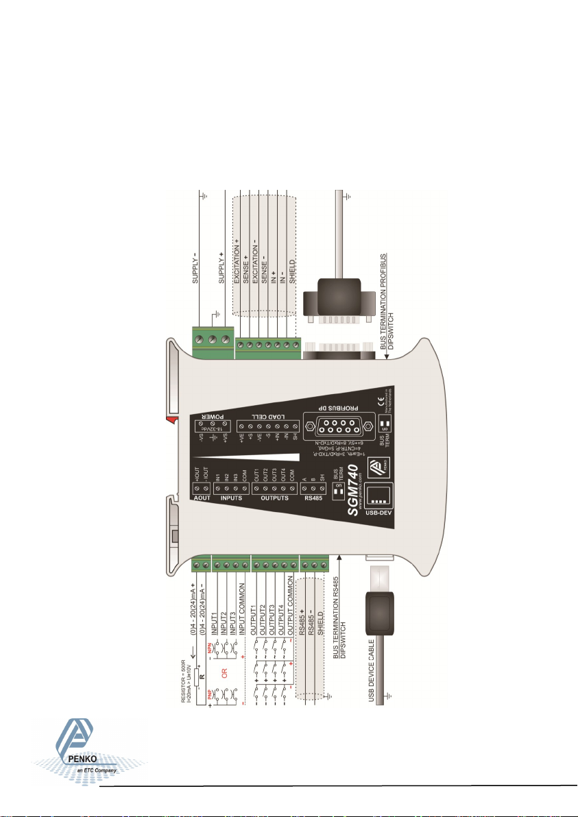
3.5 SGM740 digitizer Profibus
DC POWER
SUPPLY
18-32Vdc
6-Wire load cell
connection
Vexc=5Vdc
Profibus DP
Analoge
output
Inputs
Input 1=5khz
18-28Vdc
Outputs
Local bus
25V/0.5A
AC/DC
To PC
Config
software
12
Page 13

SGM700 Digitizer
3. Load cell / power connection
3.6 SGM740 digitizer Serial
DC POWER
SUPPLY
18-32Vdc
6-Wire load cell
connection
Vexc=5Vdc
RS232/RS422
To PC
Config
Analoge
output
Inputs
Input 1=5khz
18-28Vdc
Outputs
Local bus
25V/0.5A
AC/DC
software
13
Page 14

SGM700 Digitizer
4. First use of indicator
4.1 First use of indicator -Weigher settings-
Set up the correct indicator setting (step size and decimal point position).
The start
Turn the indicator on by connecting it to the power supply.
Press key 3 for >2 sec. to get in to Configuration Menu.
Go to the Indicator parameters pressing key 1 <2 sec. 5 times.
x5
Go into the Indicator parameters pressing key 2.
Use Ind 1 to set the maximum net weight value. Set maximum load to prevent
overload by the user. The indicator will not show any weight above the filled in
value. Range: 0 – full display.
To change the value, press key 2 <2 sec.
Use key 1 and 2 to change the value. Key 1 is for changing the number
(1-9), key 2 is for changing the position of the cursor. Confirm by pressing
key 3 for >2 sec.
Up Down Left Right Confirm
14
Page 15

SGM700 Digitizer
First use of indicator -continue-
When the maximum net weight value is set succesfully, the following screen is
visible:
Display step size
Press key 1 <2 sec. untill you see Ind 5 and press key 2 <2 sec.
Use Ind 5 to set the display step size. The step size defines the scaled parts of
the weight value. The display value will be rounded off to the nearest value with a
valid step size.
Use key 1 to select the correct step size.
Choose between 1, 2, 5, 10, 20, 50 and confirm by pressing key 3 for >2 sec.
Up Down Confirm
Done succesfully, the following screen is visible:
Decimal point
To set the Decimal point position, enter Ind 6 by pressing key 2 <2 sec.
The following screen is visible:
15
Page 16
SGM700 Digitizer
First use of indicator -continue-
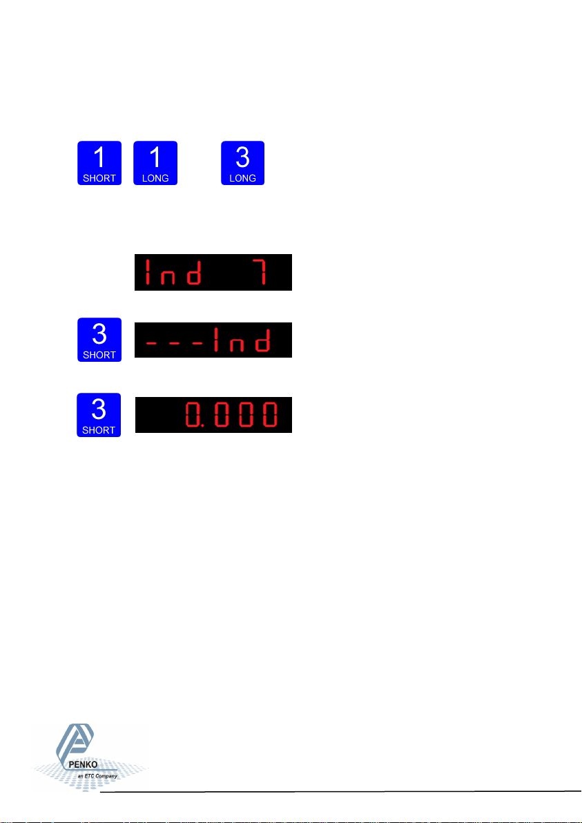
Press key 1 to define the point position and confirm by pressing key 3
for >2 sec.
Left Right Confirm
Done succesfully, the following screen is visible:
Press key 3 <2 sec to go back to Configuration Menu.
Press key 3 <2 sec to go back to main weigher display.
16
Page 17
SGM700 Digitizer
First use of indicator -continue-
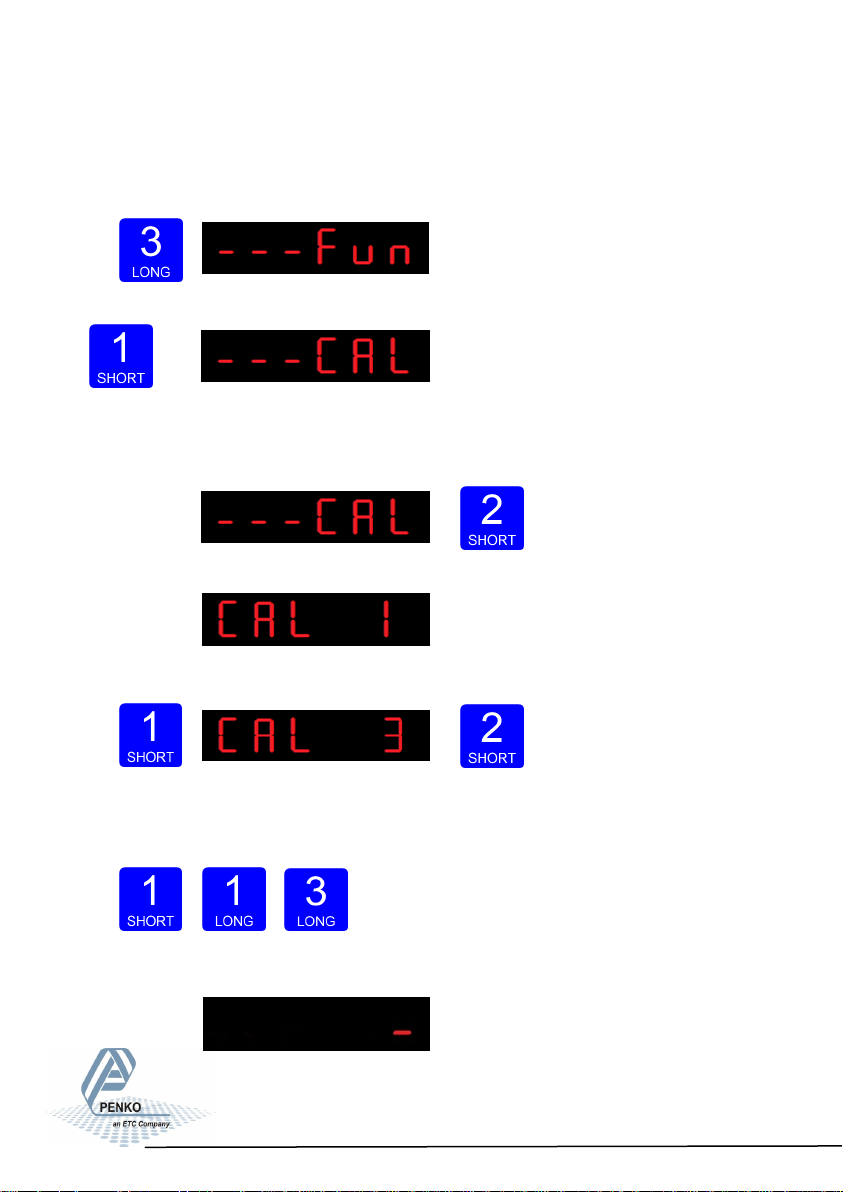
4.2 First use of indicator -CalibrationPress key 3 for >2sec. to get in to Configuration Menu.
Go to the Calibration parameters by pressing key 1 <2 sec. until you see - - - CAL
x10
Check and delete calibration points.
To enter the Calibration settings, press key 2 <2 sec.
The following screen is visible:
Press key 1 <2 sec. to go to CAL 3 and press key 2 <2 sec.
Use CAL 3 to check and delete all existing calibration points. Step through the
calibration points with key 1. Delete a calibration point by pressing
key 3 >3 sec.
Up Down Delete
During deletions, the following screen is visible:
17
Page 18

SGM700 Digitizer
First use of indicator -continue-
Calibration Settings -continue-
When a number is shown, the deletion of one calibration point is completed and
more points need to be deleted. Press key 3 >3 sec to do so.
>3 sec.
When all calibration points are deleted, the following screen is visible:
Entering new calibration points.
Use key 1 <2 sec. to go to CAL 1 and press key 2 <2 sec.
After entering, the following screen is visible:
And will automatically jump to:
First calibrate the zero point (CP1). Make sure the weigher is unloaded and
press key 3 >2 sec.
18
Page 19

SGM700 Digitizer
First use of indicator -continue-
Calibration Settings -continue-
The indicator now shows CP2 to calibrate the gain point (CP2).
And will automatically jump to:
Use key 1 and key 2 to enter the reference value. Key 1 is used for changing the
number (1-9), key 2 is used for changing the position of the cursor. Load the
weigher with the reference value and press key 3 >2 sec.
Up Down Left Right Confirm
Done succesfully the following screen is visible:
Press key 3 <2 sec. to go back to Configuration Menu.
Press key 3 <2 sec. to go back to main weigher display.
19
Page 20

SGM700 Digitizer
5. Main Menu
In the Main menu you can change the Setpoints, display the TAC code and
display the CAL code.
5.1 Setpoints.
The SGM700 has four outputs that can switch on/off on different levels.
These levels have to be filled in at the setpoint menu.
Press key 3 <2 sec. to go into the Main menu.
Press key 2 <2sec. to the setpoint change menu.
Press key 1 <2 sec. to select a diffrent setpoint (1-4). Press key 2 <2 sec. to
change the selected setpoint. Key 1 is used for changing the number (1-9), key 2
is used for changing the position of the cursor. Press key 3 >2sec. to confirm.
Up Down Left Right Confirm
When the selected setpoint is changed, the display changes to the next setpoint.
20
Page 21
SGM700 Digitizer
Main Menu -continue-
When done with changing the setpoints press key 3 <2 sec to go back to the
main weigher display
5.2 TAC code (Traceable Acces Code).
The SGM700 has a TAC code inside. TAC code is number of times the indicator
data is changed. When an indicator gets certified this number will be written on
the device and is used by the controlling agency to see if the settings aren’t
changed after sealing.
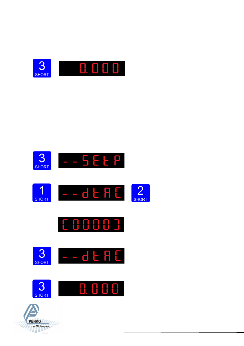
To check out the TAC code Press key 3 <2 sec. to go into the Main menu.
Press key 1 <2sec. to the dtAC menu and press key 2 <2sec. to enter.
The following screen will show the actual TAC code.
Press Key 3 <2 sec. to go back to the main menu.
Press key 3 <2 sec. to go back to the main weigher display.
21
Page 22
SGM700 Digitizer
Main Menu -continue-
5.2 CAL code (Calibration counter).
The SGM700 has a CAL code inside. CAL code is the number of times the
calibration is changed. When an indicator gets certified this number will be written
on the device and is used by the controlling agency to see if the settings aren’t
changed after sealing.
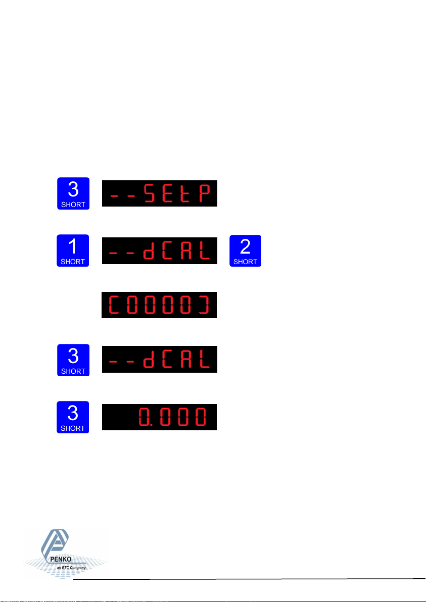
To check out the CAL code Press key 3 <2 sec. to go into the Main menu.
Press key 1 <2sec. 2x to the dCAL menu and press key 2 <2sec. to enter.
The following screen will show the actual CAL code.
Press Key 3 <2 sec. to go back to the main menu.
Press key 3 <2 sec. to go back to the main weigher display.
22
Page 23
SGM700 Digitizer
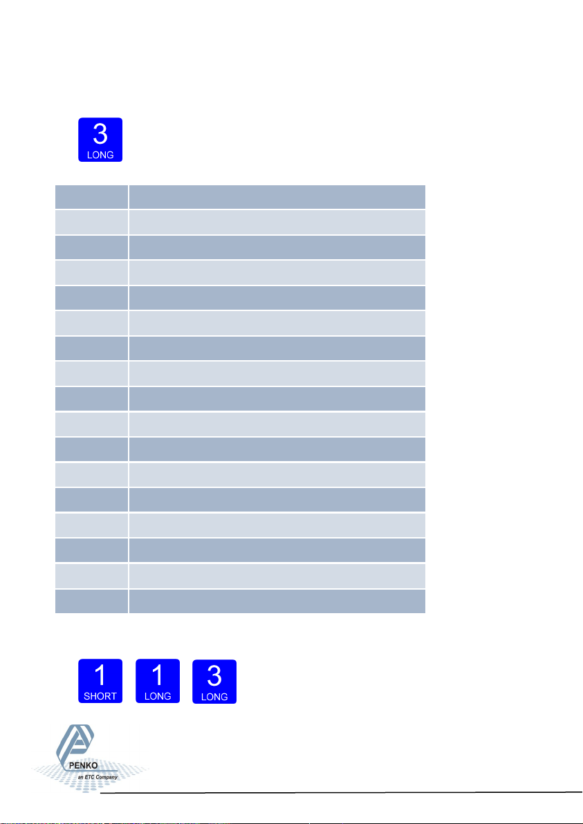
6. Configuration Menu
Press button 3 >2 sec to enter the Configuration Menu.
In the Configuration Menu the following options are available:
- - - Fun setpoint function settings
- - - ACn setpoint action settings
- - - dAC Analog output settings
- - - 485 Local bus communication settings (RS485)
- - - - Pb Profibus settings (SGM740 only)
- - - Eth Ethernet settings (SGM720 only)
- - - Ind Indicator settings
- - - rng Multi range/interval settings
- - - FIL Filter settings
- - - dSF Digital filter settings
- - - PCL Pre-calibration settings
- - - CAL Calibration settings
- - - tCL Theoretic calibration
- - - gCL Geographic calibration
- - - CLo Date and time configuration (SGM750 only)
- - - rcL Recall
- - - SoF Firmware update
Scroll thru the menu options pressing key 1 and enter a sub-menu pressing
key 2 <2 sec.
Up Down Enter
23
Page 24

SGM700 Digitizer
Configuration Menu -Fun-
6.1 - - - Fun setpoint function settings
Configure the weiger mode the outputs has to switch on press key 2 <2 sec to en-
ter the setpoint function settings menu.
Select the output you want to configure pressing key 1 <2 sec. Fun 1= output 1,
Fun 2= output 2, Fun 3= output 3 and Fun 4= output 4. Confirm the selected output
by pressing key 2 <2 sec.
The following screen is visible:
Scroll thru the weigher function options pressing key 1 and select which weigher
mode is needed by pressing key 3 >2sec. (options are: 1-17)
1 Weigher 10 Fast gross x 10
2 Fast gross 11 Fast Net x 10
3 Fast net 12 Gross x 10
4 Gross 13 Net x 10
5 Net 14 Tare x 10
6 Tare 15 Peak x 10
7 Peak 16 Valley x 10
8 Valley 17 Sample
9 Weigher x 10
For further detais on the weigher functions check appendix I
Up Down Confirm
24
Page 25
SGM700 Digitizer
Configuration Menu -ACn-
6.2 - - - ACn setpoint action settings
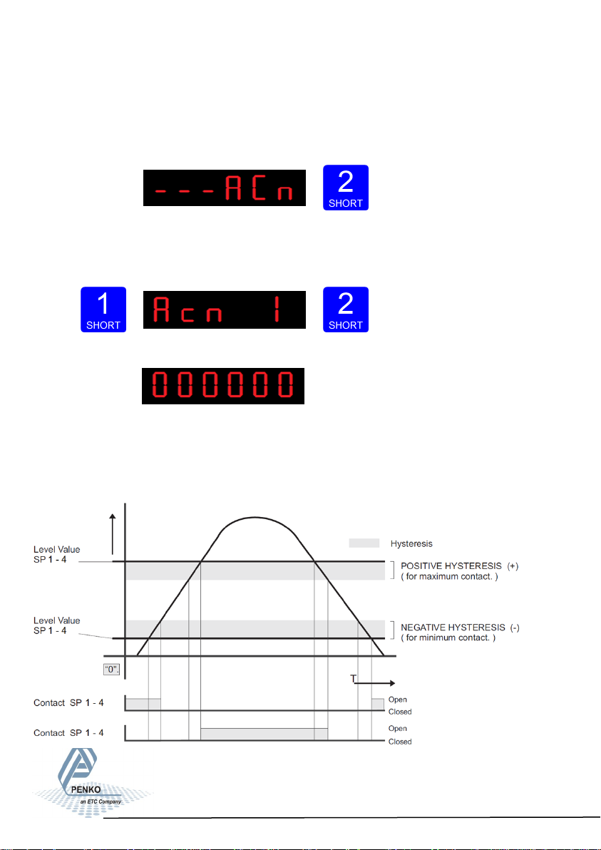
To set the hysteresis for the outputs press key 2 <2 sec to enter the setpoint
function settings menu.
Select the output you want to configure pressing key 1 <2 sec. Acn 1= output 1,
Acn 2= output 2, Acn 3= output 3 and Acn 4= output 4. Confirm the selected out-
put by pressing key 2 <2 sec.
The following screen is vissable:
Fill in the hysteresis for the outputs. Use key 1 and 2 to change the value. Key 1
is for changing the number (1-9), key 2 is for changing the position of the cursor.
Confirm by pressing key 3 for >2 sec.See diagram below. Choose value between
-99999 and 999999.
25
Page 26
SGM700 Digitizer
Configuration Menu -dAC-
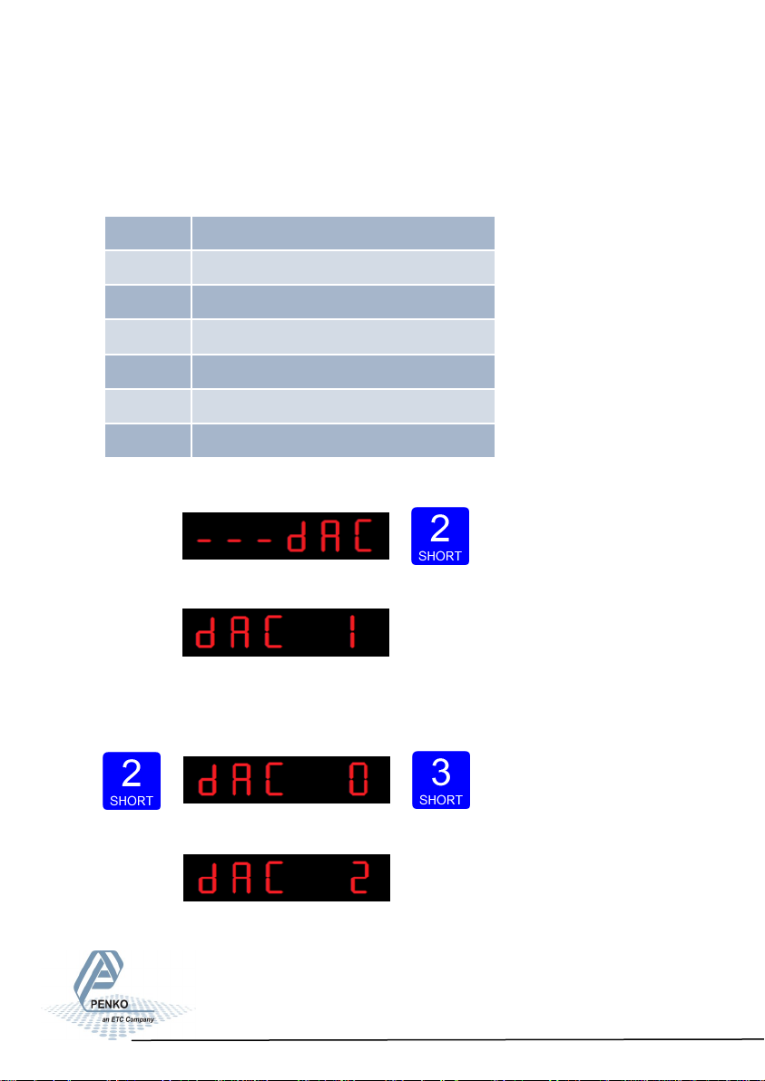
6.3 - - - dAC Analog output settings
In this menu, all analog output parameters can be set.
Options are:
Press key 2 <2 sec to enter the analog output settings.
The following screen is visible:
In dAC 1 you can set the analog output to its minimum level for testing
purpose.Press key 2 <2 sec to set the analog output to minimum.
Press key 3 <2 sec to go back.
The following screen is vissable:
dAC 1 Set analog output to minimum level
dAC 2 Set analog output to maximum level
dAC 3 Set analog output to level in percetage
dAC 4 Analog output weigher mode
dAC 5 Zero value for minimum analog output
dAC 6 End value for maximum analog output
dAC 7 Analog output range
26
Page 27

SGM700 Digitizer
Configuration Menu -dAC- -continue-
In dAC 2 you can set the analog output to its maximum level for testing purpo-
se.Press key 2 <2 sec to set the analog output to maximum. Press key 3 <2 sec
to go back.
The following screen is vissable:
In dAC 3 you can set the analog output to a level you want for testing purpose.
Press key 2 <2 sec.
Fill in the wanted percentage (0000,00-0100,00 using key 1 and key 2. Key 1 is
for changing the number (1-9), key 2 is for changing the position of the cursor.
Confirm by pressing key 3 >2 sec. Press key 3 <2 sec. to go back and reset the
analog output.
Increase Decrease Left Right Confirm Go back
The following screen is vissable:
In dAC 4 you set the weigher mode that the analog output is based on. Press key
2 < 2sec. to enter dAC 4. Scroll thru the weigher function options pressing key 1
and select which weigher mode is needed by pressing key 3 >2sec. (options are:
1-17)
Increase Decrease Confirm
27
Page 28
SGM700 Digitizer
Configuration Menu -dAC- -continue-
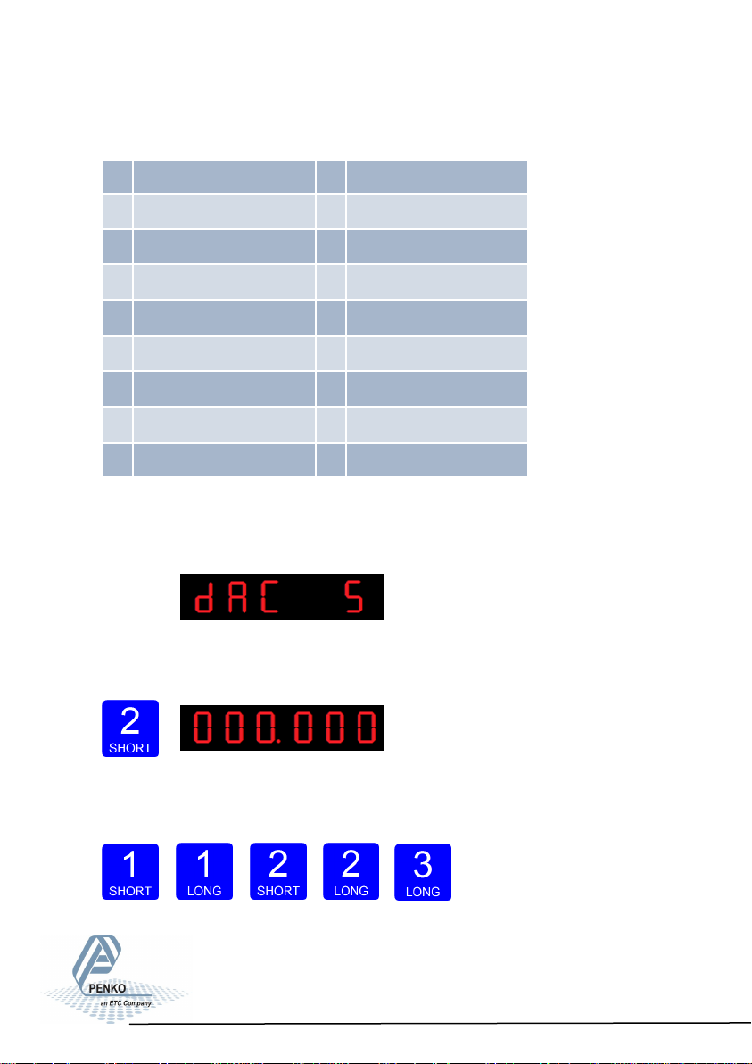
The options are:
For further detais on the weigher functions check appendix I
The following screen will be vissable:
In dAC 5 you set the weigher start value for the analog output. At this value the
analog output starts with its minimum value. Press key 2 < 2sec. to enter dAC 5.
Fill in the wanted start weight using key 1 and key 2. Key 1 is for changing the
number (1-9), key 2 is for changing the position of the cursor.
Confirm by pressing key 3 >2 sec.
Increase Decrease Left Right Confirm
1 Weigher 10 Fast gross x 10
2 Fast gross 11 Fast Net x 10
3 Fast net 12 Gross x 10
4 Gross 13 Net x 10
5 Net 14 Tare x 10
6 Tare 15 Peak x 10
7 Peak 16 Valley x 10
8 Valley 17 Sample
9 Weigher x 10
28
Page 29

SGM700 Digitizer
Configuration Menu -dAC- -continue-
The following screen will be vissable:
In dAC 6 you set the weigher end value for the analog output. At this value the
analog output stops with its maximum value. Press key 2 < 2sec. to enter dAC 6.
Fill in the wanted end value using key 1 and key 2. Key 1 is for changing the
number (1-9), key 2 is for changing the position of the cursor. Confirm by pressing key 3 >2 sec.
Increase Decrease Left Right Confirm
The following screen will be vissable:
In dAC 7 you set analog output mode. Press key 2 < 2sec. to enter dAC 7.
Scroll thru the weigher function options pressing key 1 and select which analog
output mode is needed by pressing key 3 >2sec. (options are: 1-5).
Increase Decrease Confirm
29
Page 30

SGM700 Digitizer
Configuration Menu -485-
Options are:
When confirmed the following screen will be vissable:
6.4 - - - 485 Local bus communication settings (RS485)
In this menu, the communication address can be set for communication with
multiple devices. Press key 2 <2 sec to enter the settings.
The following screen will be vissable:
In 485 1 you set the address of the SGM700. Press key 2 < 2sec. to enter 485 1.
Set the address using key 1 and key 2.. Key 1 is for changing the number
(1-9), key 2 is for changing the position of the cursor. Confirm by pressing
key 3 >2sec. (options are: 1-32).
Increase Decrease Left Right Confirm
1 RAW Register value 65535 parts
2 0-24mA input value 0 to 24 mA will be calculated from 0 to 100,00%
3 0-20mA input value 0 to 20 mA will be calculated from 0 to 100,00%
4 4-20mA input value 4 to 20 mA will be calculated from 0 to 100,00%
5 4-24mA input value 4 to 24 mA will be calculated from 0 to 100,00%
30
Page 31

SGM700 Digitizer
Configuration Menu –Pb-
6.5 - - - - Pb Profibus settings (SGM740 only)
In this menu, the communication settings can be set for profibus.
Options are:
Press key 2 <2 sec to enter the profibus settings.
The following screen will be vissable:
In Pb 1 you set the profibus address of the SGM700. Press key 2 <2 sec. to
enter Pb 1. Set the address using key 1 and key 2 confirm by pressing key 3 >2
sec. (options are: 0-255).
Increase Decrease Left Right Confirm
When confirmd the following screen will be vissable:
Pb 1 Probus address
Pb 2 Value mode
31
Page 32

SGM700 Digitizer
Configuration Menu -Pb- -continue-
In Pb 2 you set the profibus Value mode. The profibus value can be shown as
Integer (direct value without decimal point) or as Floating Point (real value with
decimal point). Press key 2 <2 sec. to change the mode.
The oprions are:
Select the option you want to use by pressing key 1 and confirm by pressing
key 3 >2 sec.
Increase Decrease Confirm
The following screen will be vissable:
Pb2 FL Floang point
Pb2 In Integer
32
Page 33
SGM700 Digitizer
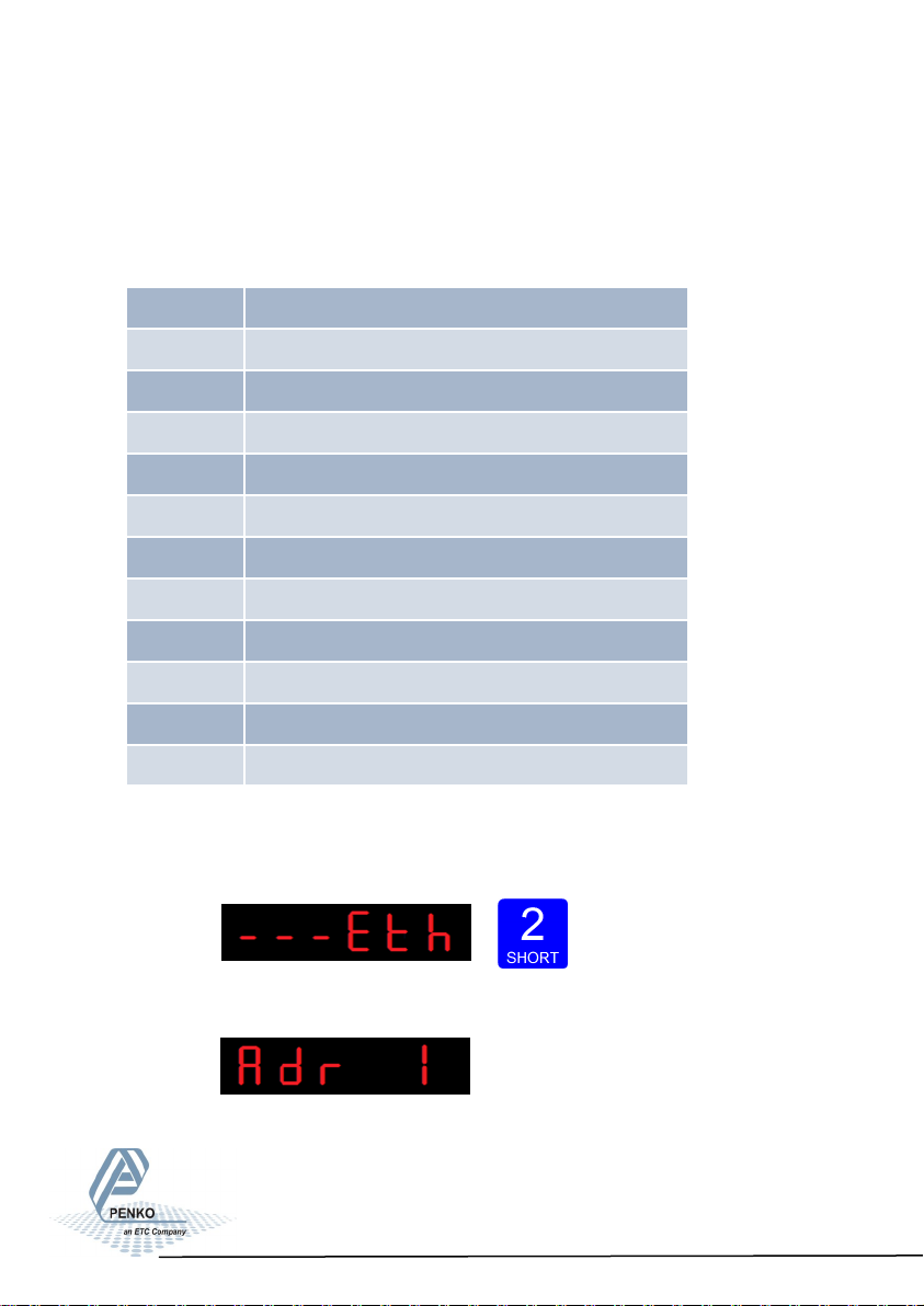
Configuration Menu -Eth-
6.6 - - - Eth Ethernet settings (SGM720 only)
In this menu, the communication settings can be set for the ethernet port.
Options are:
Press key 2 <2 sec to enter the ethernet settings.
The following screen is vissable:
Adr 1 First three numbers of the IP address
Adr 2 Second three numbers of the IP address
Adr 3 Third three numbers of the IP address
Adr 4 Fourth three numbers of the IP address
Sub 1 First three numbers of the Subnet address
Sub 2 Second three numbers of the Subnet address
Sub 3 Third three numbers of the Subnet address
Sub 4 Fourth three numbers of the Subnet address
gAt 1 First three numbers of the Gateway address
gAt 2 Second three numbers of the Gateway address
gAt 3 Third three numbers of the Gateway address
gAt 4 Fourth three numbers of the Gateway address
33
Page 34
SGM700 Digitizer
Configuration Menu -Eth- -continue-
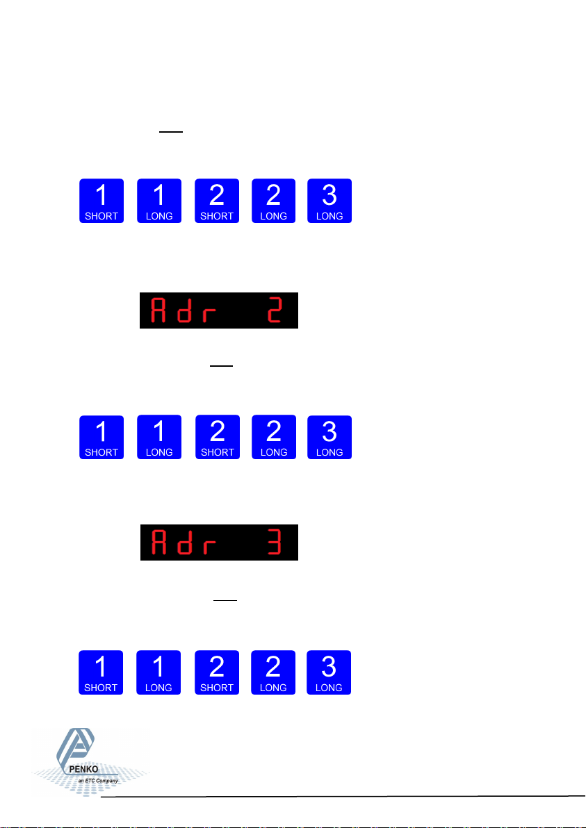
In Adr 1 you set the first three numbers of the IP address you want to give the
SGM700 (example: 192.168.151.112). Use key 1 and key 2 to change the
number Key 1 is for changing the number (1-9), key 2 is for changing the position
of the cursor. Confirm by pressing key 3 >2 sec.
Increase Decrease Left Right Confirm
When confirmed the following screen will be visible:
In Adr 2 you set the second three numbers of the IP address you want to give
the SGM700 (example: 192.168.151.112). Use key 1 and key 2 to change the
number Key 1 is for changing the number (1-9), key 2 is for changing the position
of the cursor. and confirm by pressing key 3 >2 sec.
Increase Decrease Left Right Confirm
When confirmed the following screen will be visible:
In Adr 3 you set the third three numbers of the IP address you want to give the
SGM700 (example: 192.168.151.112). Use key 1 and key 2 to change the
number Key 1 is for changing the number (1-9), key 2 is for changing the position
of the cursor. Confirm by pressing key 3 >2 sec.
Increase Decrease Left Right Confirm
34
Page 35
SGM700 Digitizer
Configuration Menu -Eth- -continue-
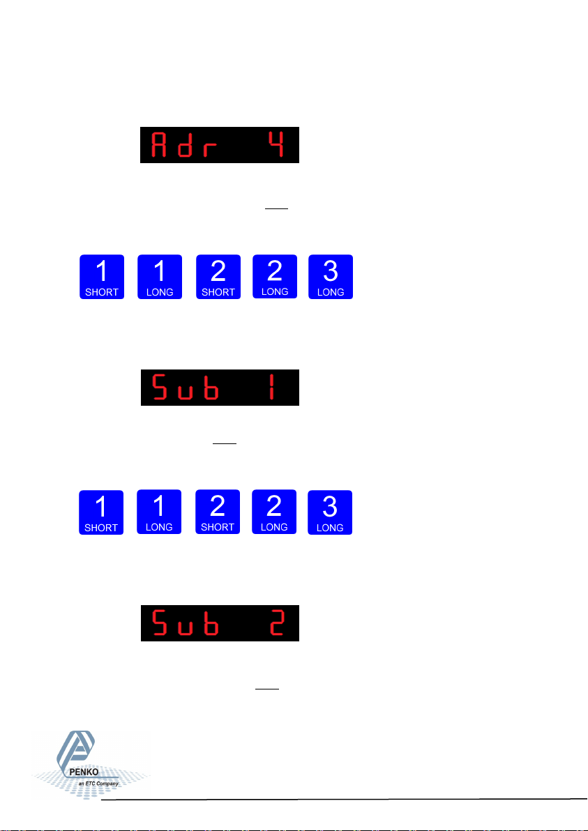
When confirmed the following screen will be visible:
In Adr 4 you set the fourth three numbers of the IP address you want to give
the SGM700 (example: 192.168.151.112). Use key 1 and key 2 to change the
number Key 1 is for changing the number (1-9), key 2 is for changing the position
of the cursor. Confirm by pressing key 3 >2 sec.
Increase Decrease Left Right Confirm
When confirmed the following screen will be visible:
In Sub 1 you set the first three numbers of the Subnet address you want to
give the SGM700 (example: 255.255.255.000). Use key 1 and key 2 to change
the number Key 1 is for changing the number (1-9), key 2 is for changing the position of the cursor. Confirm by pressing key 3 >2 sec.
Increase Decrease Left Right Confirm
When confirmed the following screen will be visible:
In Sub 2 you set the second three numbers of the Subnet address you want
to give the SGM700 (example: 255.255.255.000). Use key 1 and key 2 to change
the number Key 1 is for changing the number (1-9), key 2 is for changing the position of the cursor. Confirm by pressing key 3 >2 sec.
35
Page 36

SGM700 Digitizer
Configuration Menu -Eth- -continue-
Increase Decrease Left Right Confirm
When confirmed the following screen will be visible:
In Sub 3 you set the third three numbers of the Subnet address you want to
give the SGM700 (example: 255.255.255.000). Use key 1 and key 2 to change
the number Key 1 is for changing the number (1-9), key 2 is for changing the position of the cursor. Confirm by pressing key 3 >2 sec.
Increase Decrease Left Right Confirm
When confirmed the following screen will be visible:
In Sub 4 you set the fourth three numbers of the Subnet address you want to
give the SGM700 (example: 255.255.255.000). Use key 1 and key 2 to change
the number Key 1 is for changing the number (1-9), key 2 is for changing the position of the cursor. Confirm by pressing key 3 >2 sec.
Increase Decrease Left Right Confirm
When confirmed the following screen will be visible:
36
Page 37
SGM700 Digitizer
Configuration Menu -Eth- -continue-
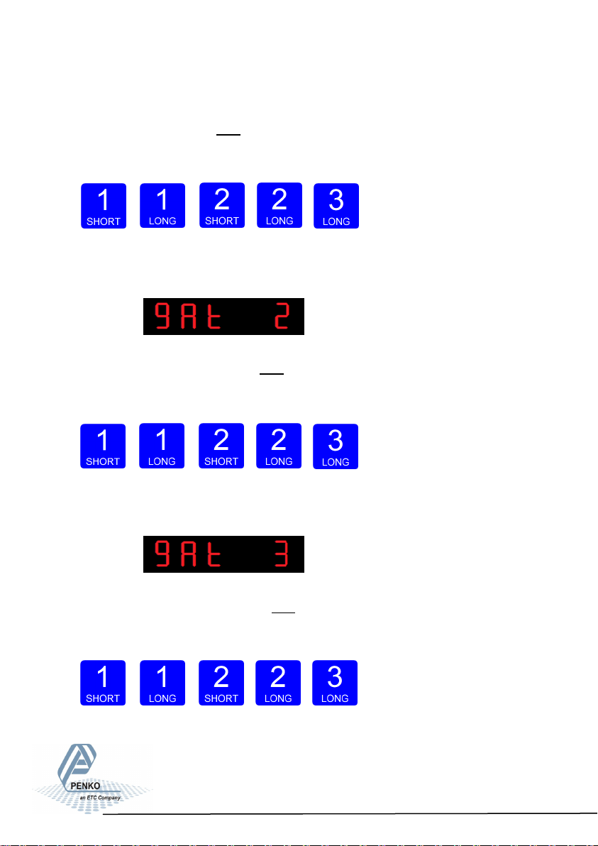
In gAt 1 you set the first first numbers of the Gateway address you want to
give the SGM700 (example: 192.168.001.001). Use key 1 and key 2 to change
the number Key 1 is for changing the number (1-9), key 2 is for changing the position of the cursor. Confirm by pressing key 3 >2 sec.
Increase Decrease Left Right Confirm
When confirmed the following screen will be visible:
In gAt 2 you set the second three numbers of the Gateway address you want
to give the SGM700 (example: 192.168.001.001). Use key 1 and key 2 to change
the number Key 1 is for changing the number (1-9), key 2 is for changing the position of the cursor. Confirm by pressing key 3 >2 sec.
Increase Decrease Left Right Confirm
When confirmed the following screen will be visible:
In gAt 3 you set the third three numbers of the Gateway address you want to
give the SGM700 (example: 192.168.001.001). Use key 1 and key 2 to change
the number Key 1 is for changing the number (1-9), key 2 is for changing the position of the cursor. Confirm by pressing key 3 >2 sec.
Increase Decrease Left Right Confirm
37
Page 38

SGM700 Digitizer
Configuration Menu -Eth- -continue-
When confirmed the following screen will be visible:
In gAt 4 you set the fourth three numbers of the Gateway address you want to
give the SGM700 (example: 192.168.001.001). Use key 1 and key 2 to change
the number Key 1 is for changing the number (1-9), key 2 is for changing the position of the cursor. Confirm by pressing key 3 >2 sec.
Increase Decrease Left Right Confirm
When confirmed the following screen will be visible:
38
Page 39

SGM700 Digitizer
Configuration Menu -Ind-
6.7 - - - Ind Indicator settings
In this menu, the Indicator settings can be set.
Options are:
Press key 2 <2 sec to enter the indicator settings.
The following screen is vissable:
In Ind 1 you set the maximum net weight value. Set maximum load to prevent
overload by the user. The indicator will not show any weight above this value.
Range: 0 – full display.
To change the value press key 2 < 2 sec.
Ind 1 Maximum display value
Ind 2 No moon band
Ind 3 Stable me
Ind 4 Digital overall lter
Ind 5 Display step size
Ind 6 Decimal point posion
Ind 7 Display refreshment speed
Ind 8 Operaon mode
Ind 9 Sample me
39
Page 40

SGM700 Digitizer
Configuration Menu -Ind- -continiue-
The following screen is vissable:
Use key 1 and 2 to change the value. Key 1 is for changing the number
(1-9), key 2 is for changing the position of the cursor. Confirm by pressing
key 3 for >2 sec.
Increase Decrease Left Right Confirm
The following screen is vissable:
In Ind 2 you set the No motion band Indicator gives stable signal when weigher
value is stable within this range and time set with Ind 3.
Choose a value between: 0 – 999999.
To change the value press key 2 < 2 sec.
The following screen is vissable:
Use key 1 and 2 to change the value. Key 1 is for changing the number
(1-9), key 2 is for changing the position of the cursor. Confirm by pressing
key 3 for >2 sec.
Increase Decrease Left Right Confirm
40
Page 41
SGM700 Digitizer
Configuration Menu -Ind- -continiue-
The following screen is vissable:
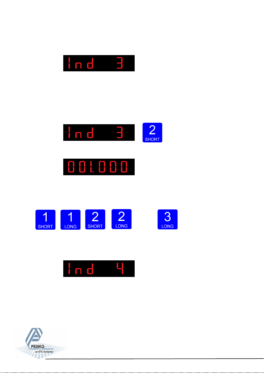
In Ind 3 you set the Stable time Indicator gives stable signal when weigher value
is stable within the range set in Ind 2 and time set with Ind 3.
Choose a value between: 000.000 – 16.959 seconds.
To change the value press key 2 < 2 sec.
The following screen is vissable:
Use key 1 and 2 to change the value. Key 1 is for changing the number
(1-9), key 2 is for changing the position of the cursor. Confirm by pressing
key 3 for >2 sec.
Increase Decrease Left Right Confirm
The following screen is vissable:
In Ind 4 you set the Digital overall lter. Set the overall filter to effect all indicator
signals used in the device. 0dB means no effect and –50dB is the strongest
damping. Choose between -: 0dB, 1: -6dB, 2: -12dB, 3: -24dB, 4: -30dB,
5: -36dB, 6: -42dB and 7: –50dB.
41
Page 42
SGM700 Digitizer
Configuration Menu -Ind- -continiue-
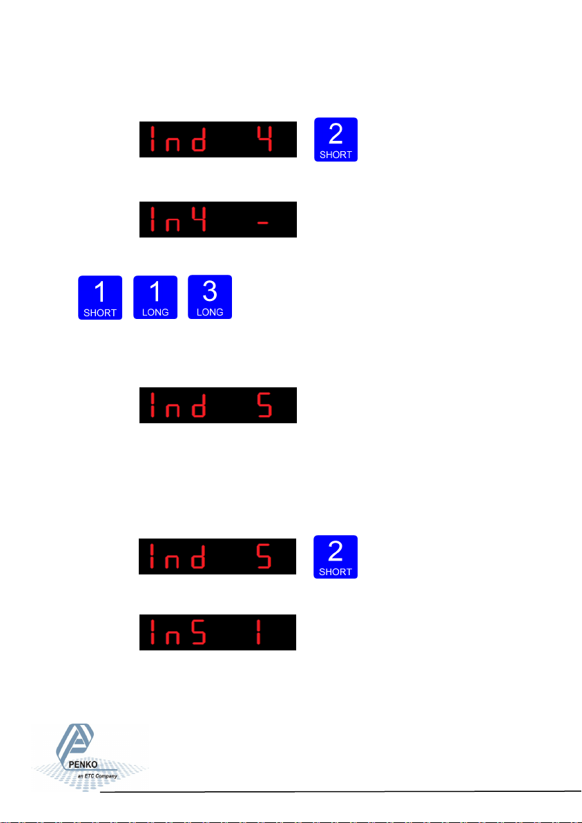
To change the filter press key 2 < 2 sec.
The following screen is vissable:
Use key 1 change the filter. Confirm by pressing key 3 for >2 sec.
Up Down Confirm
The following screen is vissable:
In Ind 5 you set the display step size. The step size defines the scaled parts of
the weight value. The display value will be rounded off to the nearest value with a
valid step size.
To change the display step size press key 2 < 2 sec.
The following screen is vissable:
42
Page 43
SGM700 Digitizer
Configuration Menu -Ind- -continiue-
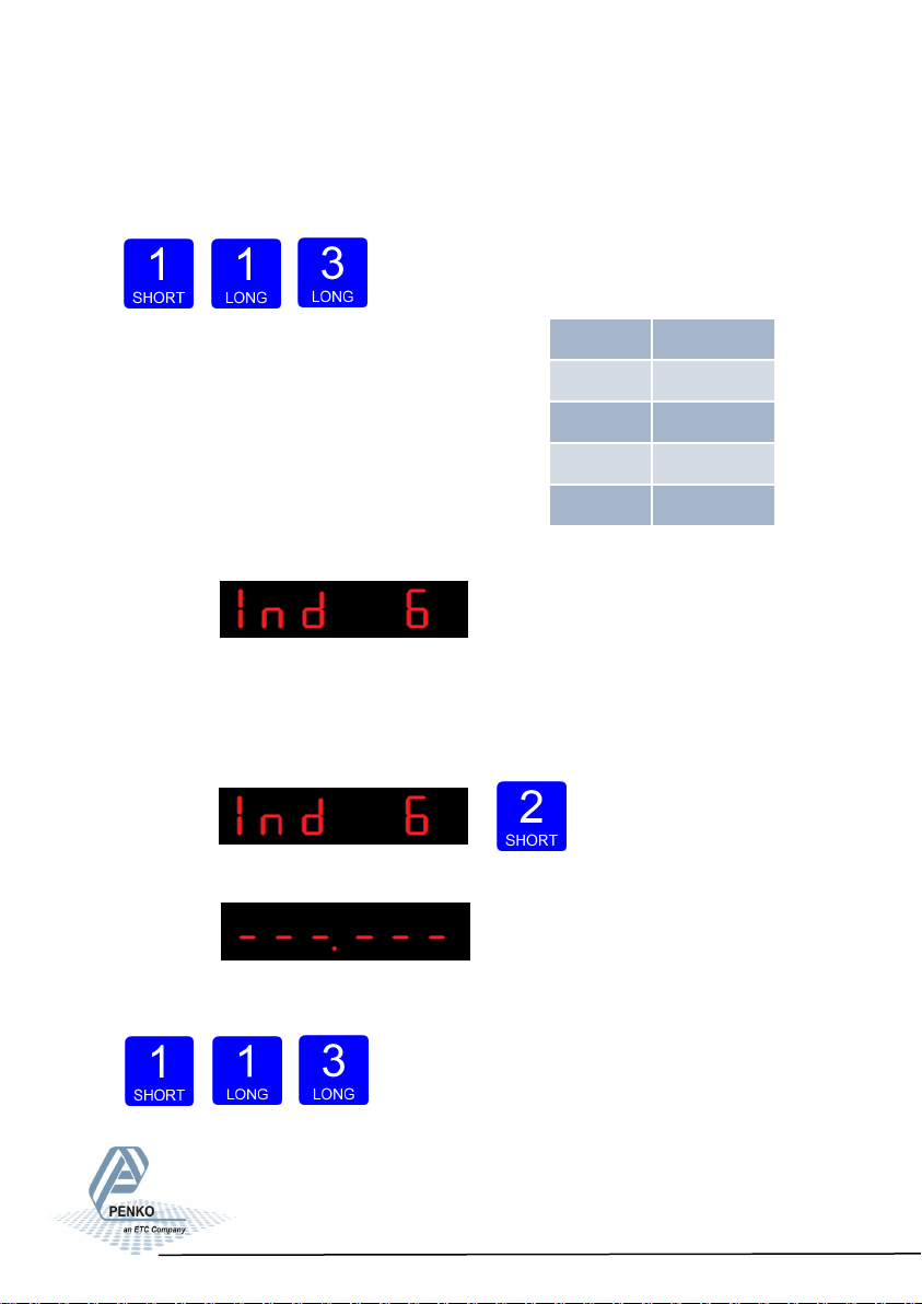
Use key 1 to select the correct step size.
Choose between 1, 2, 5, 10, 20, 50 and confirm by pressing key 3 for >2 sec.
Example step size:
weigher value is 2005 kg
Up Down Confirm
The following screen is vissable:
In Ind 6 you set the decimal point. The decimal point defines the point position
of the weight value.
To change the decimal point press key 2 < 2 sec.
The following screen is vissable:
Press key 1 to define the point position and confirm by pressing key 3 for >2 sec.
Step Size Weight (kg)
1 2005
2 2006
5 2005
10 2010
Left Right Confirm
43
Page 44

SGM700 Digitizer
Configuration Menu -Ind- -continiue-
The following screen is vissable:
In Ind 7 you set the Display refreshment speed. The Display refreshment speed
defines the times the weigher value is refresht per second. Options are: 1, 2, 3, 5,
10, 25, 50.
To change the display refreshment speed press key 2 < 2 sec.
The following screen is vissable:
Press key 1 to choose the display refreshment speed and confirm by pressing
key 3 for >2 sec.
Up Down Confirm
The following screen is vissable:
44
Page 45
SGM700 Digitizer
Configuration Menu -Ind- -continiue-
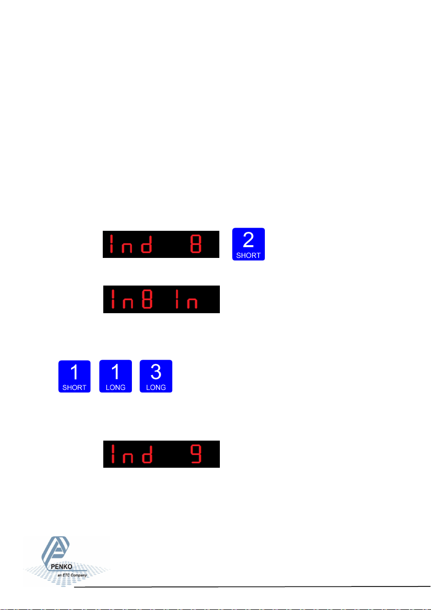
In Ind 8 you set the operation mode of the SGM700. Set the operation mode of
the unit to Industrial or Certified. In Industrial mode it’s always possible to change
the indicator parameters and calibration. In certified mode the unit will be sealed
by marks and also the weighing parameters will be blocked to satisfy to the calibration laws. A weighing unit must be certified when it’s used for measuring for
trade aims. Note: In certified mode the zero band = 4% (+2 and -2%). Also zero
suppressing (FIL 3) is disabled.
Opons are: In = Industrial mode, CE = Cered mode.
To change the operation mode press key 2 < 2 sec.
The following screen is vissable:
Press key 1 to choose the operation mode and confirm by pressing key 3 for >2
sec.
Up Down Confirm
The following screen is vissable:
In Ind 9 you set the sample rate of the indicator. The sample rate is the refresh-
ment speed of the weigher signal.
Options are: 10, 20, 25, 50, 100, 200, 400, 800, 1600 samples/sec.
45
Page 46

SGM700 Digitizer
Configuration Menu -rng-
To change the sample rate press key 2 < 2 sec.
The following screen is vissable:
Press key 1 to choose the sample rate and confirm by pressing key 3 for >2 sec.
Up Down Confirm
The following screen is vissable:
6.8 - - - rng Multi range/interval settings
In this menu, the multi range/interval can be set.
Options are:
Press key 2 <2 sec to enter the multi range/interval settings.
Rng 1 Number of display divisions
Rng 2 Maximum auto range step size
Rng 3 Auto range reset opon
46
Page 47
SGM700 Digitizer
Configuration Menu -rng- -continue-
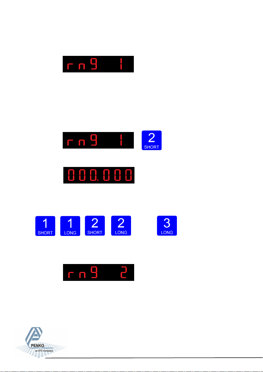
The following screen is vissable:
In rng 1 you set the number of display divisions. Set the number of divisions
when the indicator has to display with the next step size. Auto ranging starts with
step size set at Ind 5 and is disabled when range size is set to 0. Choose a value
between 000.00 and 999.999.
To change the value press key 2 < 2 sec.
The following screen is vissable:
Use key 1 and 2 to change the value. Key 1 is for changing the number
(1-9), key 2 is for changing the position of the cursor. Confirm by pressing
key 3 for >2 sec.
Up Down Left Right Confirm
The following screen is vissable:
In rng 2 you set the maximum auto range step size. Set the biggest step size
allowed. Choose between 1, 2, 5, 10, 20, 50, 100, 200 and 500.
47
Page 48

SGM700 Digitizer
Configuration Menu -rng- -continue-
To change the maximum step size press key 2 < 2 sec.
The following screen is vissable:
Use key 1 change the filter. Key 1 is for changing the number.
Confirm by pressing key 3 for >2 sec.
Up Down Confirm
Example Max Step:
If the settings are:
Step size = 1, Range = 100 and Max.
Step = 50, the table on the right shows the
accompanying step size with which the
weigher values reduces within the displayed
ranges.
When the indicator is set certified, the
maximum preset tare is equal to the first
level of the autorange. In this example the
preset tare is valid to 100.
Displayed range Step size
0-100 1
100-200 2
200-500 5
500-1000 10
1000-2000 20
2000-5000+ 50
The following screen is vissable:
48
Page 49

SGM700 Digitizer
Configuration Menu -FIL-
In rng 3 you set the auto range reset option. Choose between:
oF: Multi Range = the highest shown step size will be reseted after the signal has
been lower or equal to zero
on: Mulit Interval = the highest shown step size will be reseted after the signal
reaches the previous range.
To change the auto range reset option press key 2 < 2 sec.
The following screen is vissable:
Use key 1 change the reset option. Confirm by pressing key 3 for >2 sec.
Up Down Confirm
6.9 - - FIL Filter settings
In this menu, the filter settings can be set. The display filter will damp the weigh-
er signal to the display to get a calm display view.
Options are:
Press key 2 <2 sec to enter the filter settings.
FIL 1 Display lter band
FIL 2 Display lter factor
FIL 3 Zero suppressing
49
Page 50
SGM700 Digitizer
Configuration Menu -FIL- -continue-
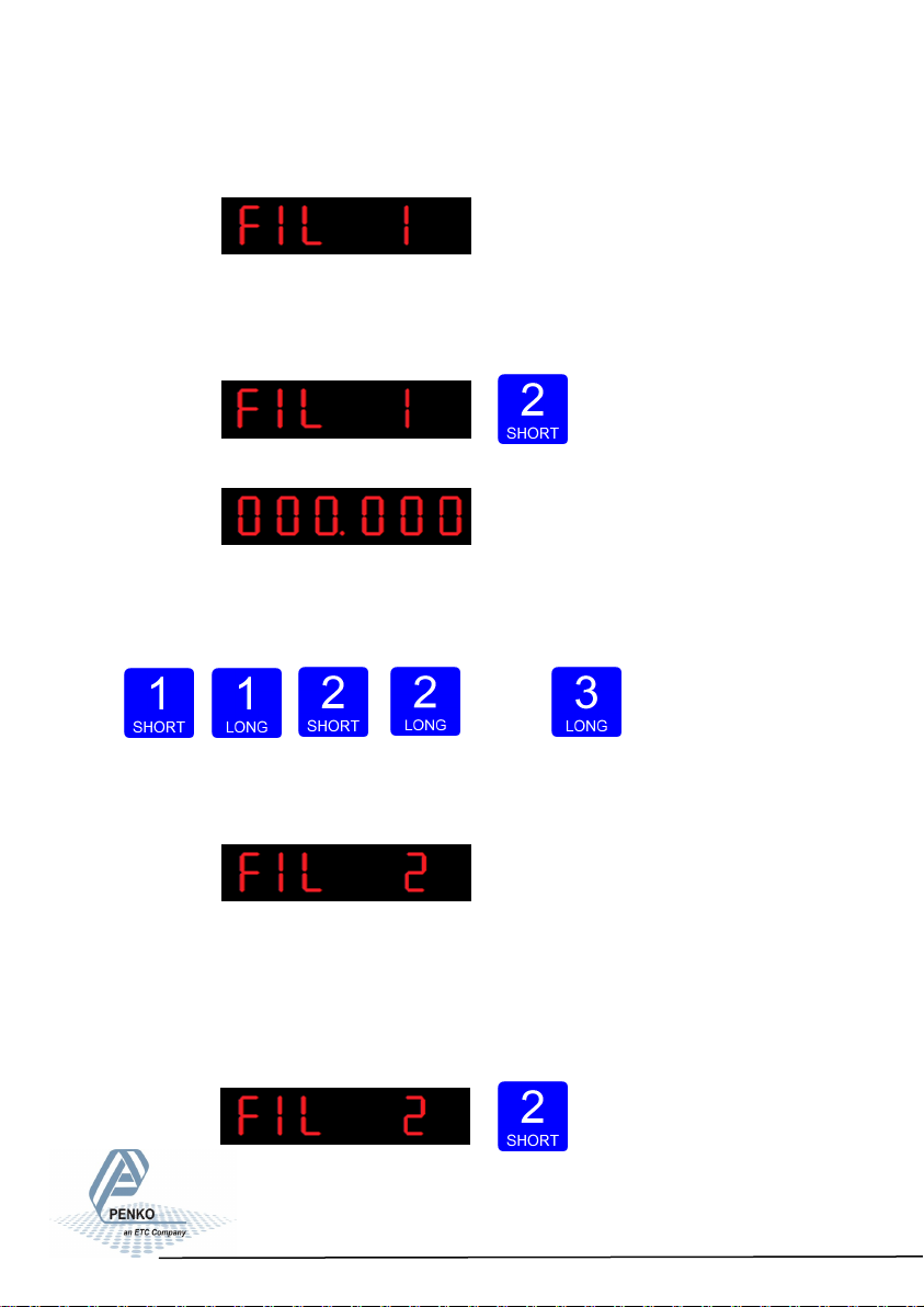
The following screen is visible:
In FIL 1 you can set the display filter band. Set the band where the filter is
active. This parameter works together wit FIL 2. Choose a value between –99999
kg and 999999 kg. Press key 2 <2 sec. to change the filter band.
The following screen is visible:
Use key 1 and 2 to change the value. Key 1 is for changing the number
(1-9), key 2 is for changing the position of the cursor. Confirm by pressing
key 3 for >2 sec.
Up Down Left Right Confirm
The following screen is visible:
In FIL 2 you can set the display filter factor. Set the strength of the filter.
0dB means no effect and –50 is the strongest damping. This parameter works
together wit FIL 1. Choose between -: 0dB, 1: -6dB, 2: -12dB, 3: -18dB, 4: -24dB,
5: -30dB, 6: -36dB, 7: -42dB and 8: -50dB.
Press key 2 <2 sec. to change the filter factor.
50
Page 51
SGM700 Digitizer
Configuration Menu -FIL- -continue-
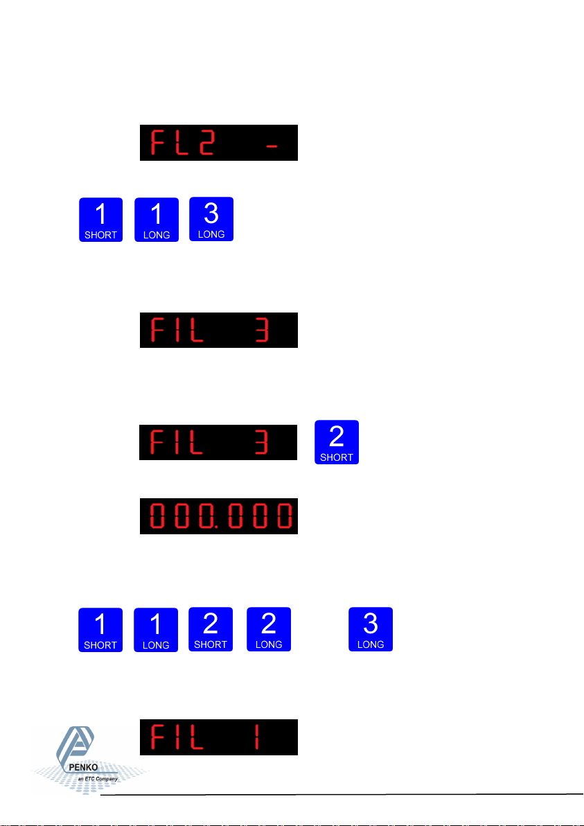
The following screen is visible:
Use key 1 change the filter. Confirm by pressing key 3 for >2 sec.
Up Down Confirm
.
The following screen is visible:
In FIL 3 you set the band within the indicator will show 0. When the indicator is
certified, this parameter will be disabled. Choose a value between 000000 and
999999. Press key 2 <2 sec. to change the zero suppressing band.
The following screen is visible:
Use key 1 and 2 to change the value. Key 1 is for changing the number
(1-9), key 2 is for changing the position of the cursor. Confirm by pressing
key 3 for >2 sec.
Up Down Left Right Confirm
The following screen is visible:
51
Page 52

SGM700 Digitizer
Configuration Menu -dSF-
6.10 - - - dSF Digital filter settings
In this menu, the digital filter settings can be set. This filter is a 2nd order filter.
The filter effects all signals up to and including the cutoff frequency. Options are:
Press key 2 <2 sec to enter the digital filter settings.
The following screen is visible:
In dSF 1 you can set the filter type.
Choose between None, Dynamic and Static. Dynamic application = used when
the weighing signal is constantly changing. Static application = used when the
weighing signal is stable . Press key 2 <2 sec. to change the filter band.
The following screen is visible:
Use key 1 change the filter type. Confirm by pressing key 3 for >2 sec.
Up Down Confirm
dSF 1 Filter type
dSF 2 Cuto frequency
dSF 3 Moving average cuto frequency
52
Page 53

SGM700 Digitizer
Configuration Menu -dSF- -continue-
The following screen is visible:
In dSF 2 you can set the Cutoff frequency. Determines the range used for
filtering the signal. Choose between oFF, 1.0Hz, 1.4Hz, 2.5Hz, 5.0Hz, 10.0Hz,
20.0Hz and 40Hz. Press key 2 <2 sec. to change the cutoff frequency range.
The following screen is visible:
Use key 1 change the cutoff frequency. Confirm by pressing key 3 for >2 sec.
Up Down Confirm
The following screen is visible:
In dSF 3 you can set the moving average cutoff frequency. Choose a value
between 0-320 Hz. Press key 2 <2 sec. to change the cutoff frequency range.
The following screen is visible:
53
Page 54
SGM700 Digitizer
Configuration Menu -PCL-
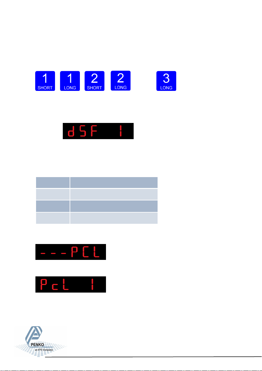
Use key 1 and 2 to change the value. Key 1 is for changing the number
(1-9), key 2 is for changing the position of the cursor. Confirm by pressing
key 3 for >2 sec.
Up Down Left Right Confirm
The following screen is visible:
6.11 - - - PCL Pre-calibration settings
In this menu, the Pre-calibration settings can be set. Options are:
Press key 2 <2 sec to enter the pre-calibration settings.
The following screen is visible:
Pcl 1 Polarity of input range
PcL 2 Cuto frequency
PcL 3 Input oset
PcL 4 Recall pre-calibraon
54
Page 55
SGM700 Digitizer
Configuration Menu -PCL- -continue-
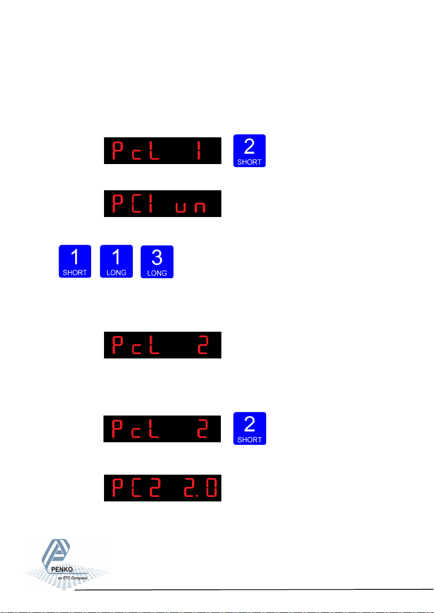
In PcL 1 you can set the polaritiy of the input range. Un=Unipolar mode the
input range for load cells is –0.2 mV/V to + value set at Range. Bi=Bipolar mode
the input range for load cells is –value set at Range to + value set at
Range.Press key 2 <2 sec. To change the polaritity og the input range.
The following screen is visible:
Use key 1 change the polarity. Confirm by pressing key 3 for >2 sec.
Up Down Confirm
The following screen is visible:
In PcL 2 you can set the Amplifier sensitivity. Choose between 1.0mV/V,
1.5mV/V, 2.0mV/V, 2.5mV/V and 3.0mV/V. Press key 2 <2 sec. to change the
amplifier sensitivity.
The following screen is visible:
55
Page 56
SGM700 Digitizer
Configuration Menu -PCL- -continue-
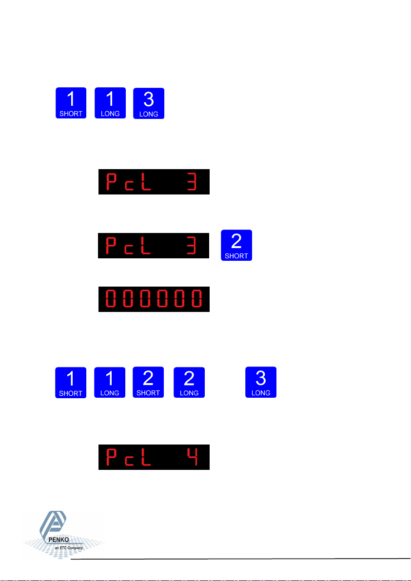
Use key 1 change the sensitiviy. Confirm by pressing key 3 for >2 sec.
Up Down Confirm
The following screen is visible:
In PcL 3 you can set the Input offset. Choose between choose a sample value
between –50000 and 50000. Press key 2 <2 sec. to change the input offset
The following screen is visible:
Use key 1 and 2 to change the value. Key 1 is for changing the number
(1-9), key 2 is for changing the position of the cursor. Confirm by pressing
key 3 for >2 sec.
Up Down Left Right Confirm
The following screen is visible:
In PcL you can Recall the Pcl parameters.The PcL parameters will be reset to
its factory settings. Press key 2 <2 sec. to recall to factory settings
56
Page 57
SGM700 Digitizer
Configuration Menu -CAL-
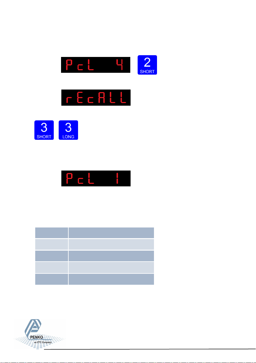
The following screen is visible:
The following screen is visible:
To recall the factory settings press key 3 >2 sec. To cancel press key 3 <2 sec.
Cancel Recall
The following screen is visible:
6.12 - - - CAL Calibration settings
In this menu, the Calibration settings can be set. Options are:
CAL 1 Add calibraon point
CAL 2 Check weiger informaon
CAL 3 Show/remove calibraon points
CAL 4 Deadload compensaon
CAL 5 Show CAL code
57
Page 58

SGM700 Digitizer
Configuration Menu -CAL- -continue-
Press key 2 <2 sec to enter the calibration settings.
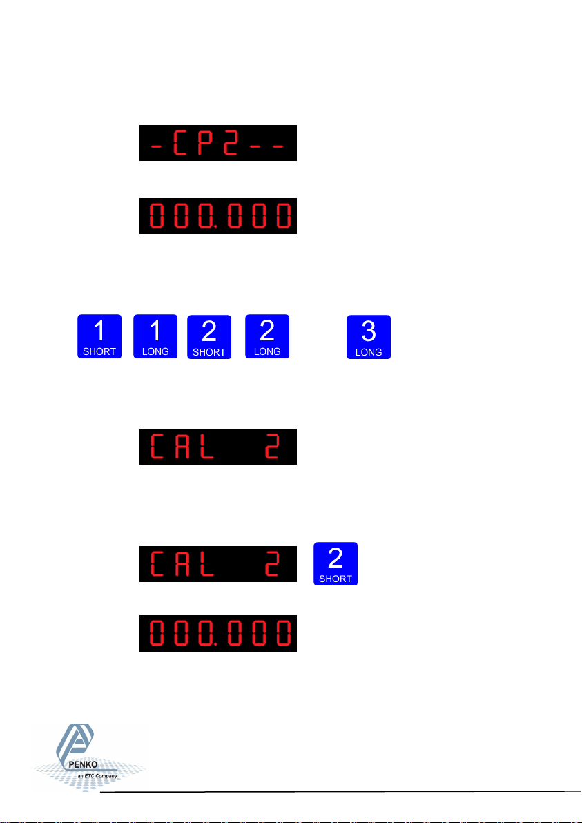
The following screen is visible:
In CAL 1 you can set the calibration points for the weigher. Press key 2 <2 sec.
to set the calibration points.
After entering, the following screen is visible (if there are no calibration points
available):
And will automatically jump to:
First calibrate the zero point (CP1). Make sure the weigher is unloaded and
press key 3 >2 sec.
58
Page 59
SGM700 Digitizer
Configuration Menu -CAL- -continue-
The indicator now shows CP2 to calibrate the gain point (CP2).
And will automatically jump to:
Use key 1 and key 2 to enter the reference value. Key 1 is used for changing the
number (1-9), key 2 is used for changing the position of the cursor. Load the
weigher with the reference value and press key 3 >2 sec.
Up Down Left Right Confirm
Done succesfully the following screen is visible:
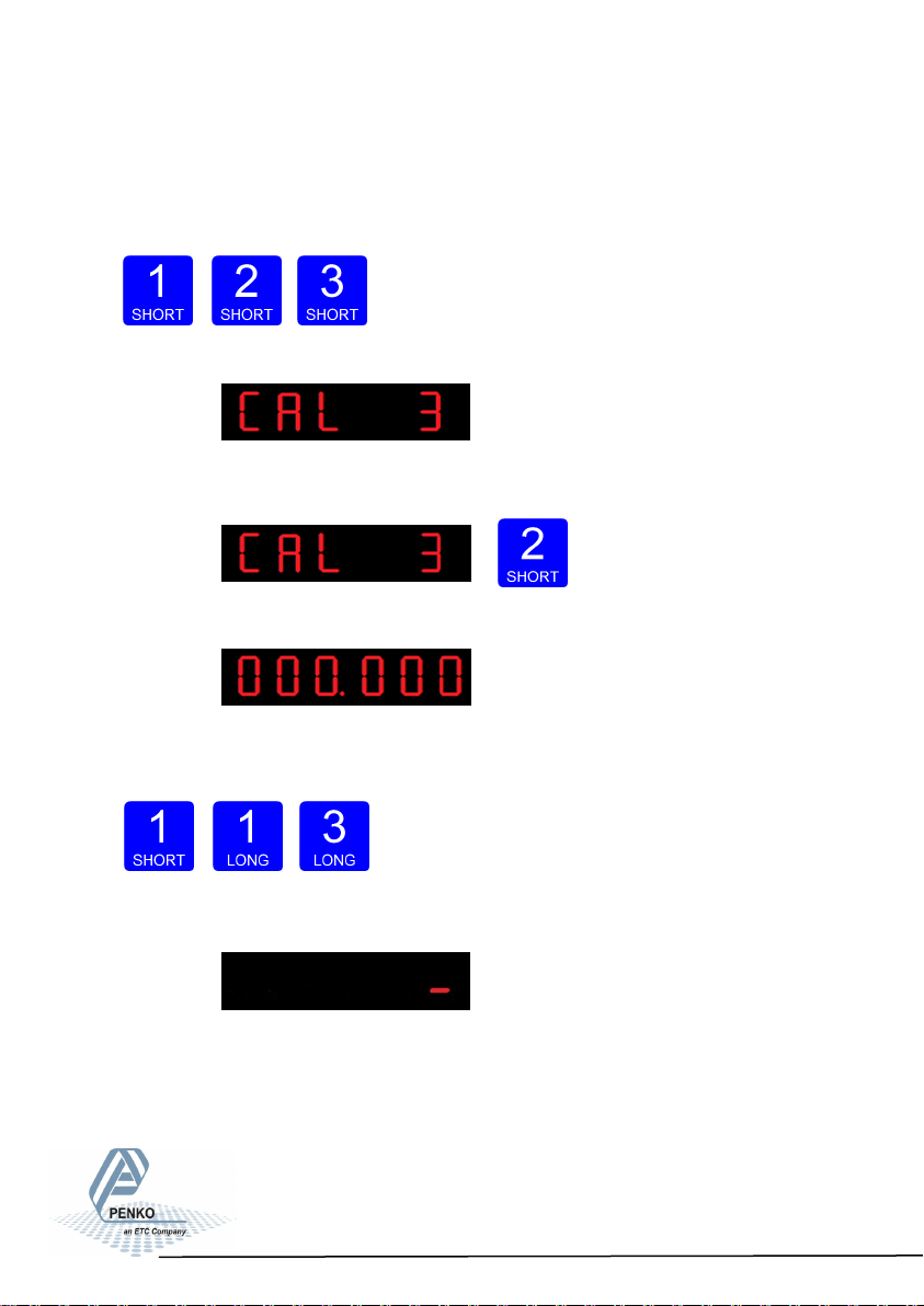
In CAL 2 you can check the weiger information. You can check out the, actual
weigher value, actual weigher value x10 and the actual ADC value.
Press key 2 <2 sec. to check out the weigher information.
The following screen is visible:
59
Page 60
SGM700 Digitizer
Configuration Menu -CAL- -continue-
Use key 1 <2 sec. to toggle between the actual weight and the actual weight x10.
Use key 2 <2 sec. to toggle between the actual weight and the ADC value.
When finished press key 3< 2 sec.
The following screen is visible:
Use CAL 3 to check and delete all existing calibration points.
Press key 2 <2 sec. to enter CAL 3.
The following screen is visible:
Step through the calibration points with key 1. Delete a calibration point by
pressing key 3 >3 sec.
Up Down Delete
During deletions, the following screen is visible:
60
Page 61
SGM700 Digitizer
Configuration Menu -CAL- -continue-
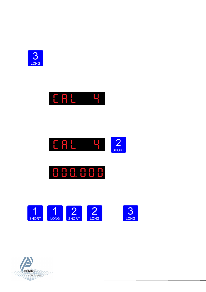
When a number is shown, the deletion of one calibration point is completed and
more points need to be deleted. Press key 3 >3 sec to do so.
>3 sec.
When all calibration points are deleted, the following screen is visible:
In CAL 4 you can set a Deadload compensation. In this menu, the deadload
can be set to pull the whole weighing line back to zero. The zero point could be
different because of some modification on the scale or dirt. Press key 2 <2 sec. to
set a new deadload compensation.
The following screen is visible:
Use key 1 and key 2 to enter the weight that is in/on the weigher. Key 1 is used
for changing the number (1-9), key 2 is used for changing the position of the
cursor. And press key 3 >2 sec.to set the new deadload.
Up Down Left Right Confirm
61
Page 62

SGM700 Digitizer
Configuration Menu -tCL-
Normally, the deadload is zero, but it is possible to change the line position if
there is weight on the scale. To do so, edit the actual weigh value to the new
known value.
When the new dead load is set the following screen is visible:
6.13 - - - tCL Theoretic calibration
In this menu, the Theoretic calibration settings can be set. Here you can set a
calibration without using a refrence weight. For this you only need the specificati-
on sheets of the used loadcells. Options are:
tCL 1 Maximum load loadcells
tCL 2 Sensivity loadcell 1
tCL 3 Sensivity loadcell 2
tCL 4 Sensivity loadcell 3
tCL 5 Sensivity loadcell 4
62
Page 63
SGM700 Digitizer
Configuration Menu -tCL- -continue-
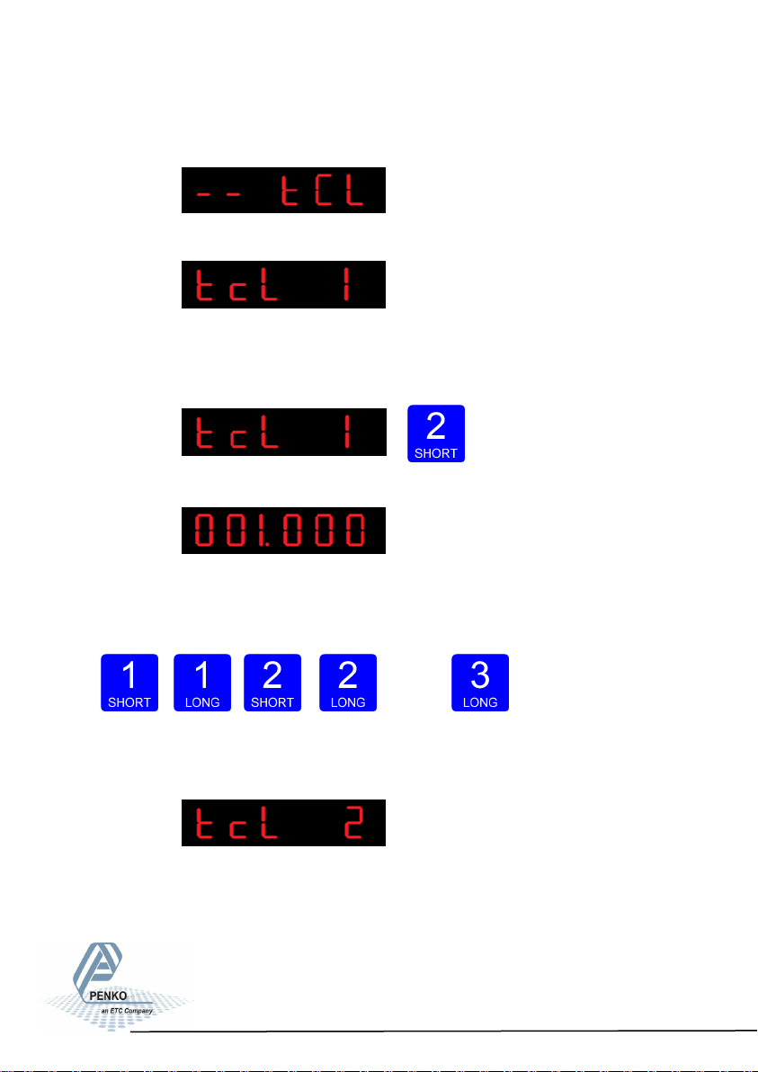
Press key 2 <2 sec to enter the theoreatic calibration settings.
The following screen is visible:
In tcL 1 you can set the maximum loadcell load. When more then one loadcell
is used all loadcells should have the same maximum load. Press key 2 <2 sec. to
set the maximum load.
The following screen is visible:
Use key 1 and key 2 to enter the maximum load of the loadcell(s). Key 1 is used
for changing the number (1-9), key 2 is used for changing the position of the
cursor. And press key 3 >2 sec.to set the maximum load.
Up Down Left Right Confirm
The following screen is visible:
In tcL 2 you can set the loadcell sensitivity for loadcell 1. This information can
be found on the datasheet deliverd with the loadcell. Press key 2 <2 sec. to set
the loadcell sensitivity.
63
Page 64

SGM700 Digitizer
Configuration Menu -tCL- -continue-
The following screen is visible:
Use key 1 and key 2 to enter the sensitivitiy of loadcell 1. Key 1 is used for
changing the number (1-9), key 2 is used for changing the position of the
cursor. Sensitivity has to be filled in as 0.00000 mV/V. Press key 3 >2 sec. to set
the sensitivity of the loadcell.
Up Down Left Right Confirm
The following screen is visible:
In tcL 3 you can set the loadcell sensitivity for loadcell 2. This information can
be found on the datasheet deliverd with the loadcell. Press key 2 <2 sec. to set
the loadcell sensitivity.
The following screen is visible:
64
Page 65

SGM700 Digitizer
Configuration Menu -tCL- -continue-
Use key 1 and key 2 to enter the sensitivitiy of loadcell 2. Key 1 is used for
changing the number (1-9), key 2 is used for changing the position of the
cursor. Sensitivity has to be filled in as 0.00000 mV/V. Press key 3 >2 sec. to set
the sensitivity of the loadcell.
Up Down Left Right Confirm
The following screen is visible:
In tcL 4 you can set the loadcell sensitivity for loadcell 3. This information can
be found on the datasheet deliverd with the loadcell. Press key 2 <2 sec. to set
the loadcell sensitivity.
The following screen is visible:
Use key 1 and key 2 to enter the sensitivitiy of loadcell 3. Key 1 is used for
changing the number (1-9), key 2 is used for changing the position of the
cursor. Sensitivity has to be filled in as 0.00000 mV/V. Press key 3 >2 sec. to set
the sensitivity of the loadcell.
Up Down Left Right Confirm
65
Page 66

SGM700 Digitizer
Configuration Menu -tCL- -continue-
The following screen is visible:
In tcL 5 you can set the loadcell sensitivity for loadcell 4. This information can
be found on the datasheet deliverd with the loadcell. Press key 2 <2 sec. to set
the loadcell sensitivity.
The following screen is visible:
Use key 1 and key 2 to enter the sensitivitiy of loadcell 4. Key 1 is used for
changing the number (1-9), key 2 is used for changing the position of the
cursor. Sensitivity has to be filled in as 0.00000 mV/V. Press key 3 >2 sec. to set
the sensitivity of the loadcell.
Up Down Left Right Confirm
The following screen is visible:
66
Page 67

SGM700 Digitizer
Configuration Menu -gCL-
6.14 - - - gCL Geographic calibration
In this menu, the Geographic calibration settings can be set. Here you can set
a geographic information of the loadcells filled in al tCL. Options are:
Press key 2 <2 sec to enter the Geographic calibration settings.
The following screen is visible:
In gcL 1 you can set the origin latitude of the loadcell. This is the geographic
latitude of where the loadcell is manufactured. Press key 2 <2 sec. to set the
origin latitude.
The following screen is visible:
Use key 1 and key 2 to enter the origin latitide of the loadcell(s). Key 1 is used for
changing the number (1-9), key 2 is used for changing the position of the
cursor. And press key 3 >2 sec.to set the origin latitude. Choose value
between –90,00 and 90,00°
gCL 1 Origin latude
gCL 2 Origin elevaon
gCL 3 Locaon latude
gCL 4 Locaon elevaon
67
Page 68
SGM700 Digitizer
Configuration Menu -gCL- -continue-
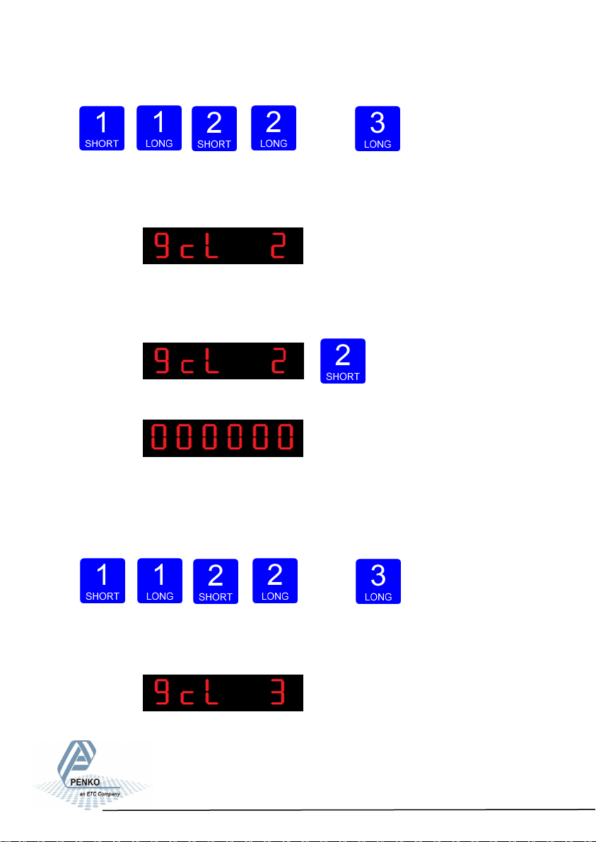
Up Down Left Right Confirm
The following screen is visible:
In gcL 2 you can set the origin elevation of the loadcell. This is the geographic
elevation of where the loadcell is manufactured. Press key 2 <2 sec. to set the
origin elevation.
The following screen is visible:
Use key 1 and key 2 to enter the origin elavation of the loadcell(s). Key 1 is used
for changing the number (1-9), key 2 is used for changing the position of the
cursor. And press key 3 >2 sec.to set the origin elevation. Choose value
between –1000 and 30000 meter.
Up Down Left Right Confirm
The following screen is visible:
68
Page 69

SGM700 Digitizer
Configuration Menu -gCL- -continue-
In gcL 3 you can set the location latiude of the loadcell(s). This is the
geographic latitude of where the loadcell is going to be used. Press key 2 <2 sec.
to set the location latitude.
The following screen is visible:
Use key 1 and key 2 to enter the location latitude of the loadcell(s). Key 1 is used
for changing the number (1-9), key 2 is used for changing the position of the
cursor. And press key 3 >2 sec.to set the location latitude. Choose value
between –90,00 and 90,00°
Up Down Left Right Confirm
The following screen is visible:
In gcL 4 you can set the location elevation of the loadcell. This is the
geographic elevation of where the loadcell is going to be used. Press key 2 <2
sec. to set the location elevation.
The following screen is visible:
69
Page 70
SGM700 Digitizer
Configuration Menu –CLo-
Use key 1 and key 2 to enter the location elevation of the loadcell(s). Key 1 is
used for changing the number (1-9), key 2 is used for changing the position of the
cursor. And press key 3 >2 sec.to set the location latitude. Choose value
between –1000 and 30000 meter.
Up Down Left Right Confirm
The following screen is visible:
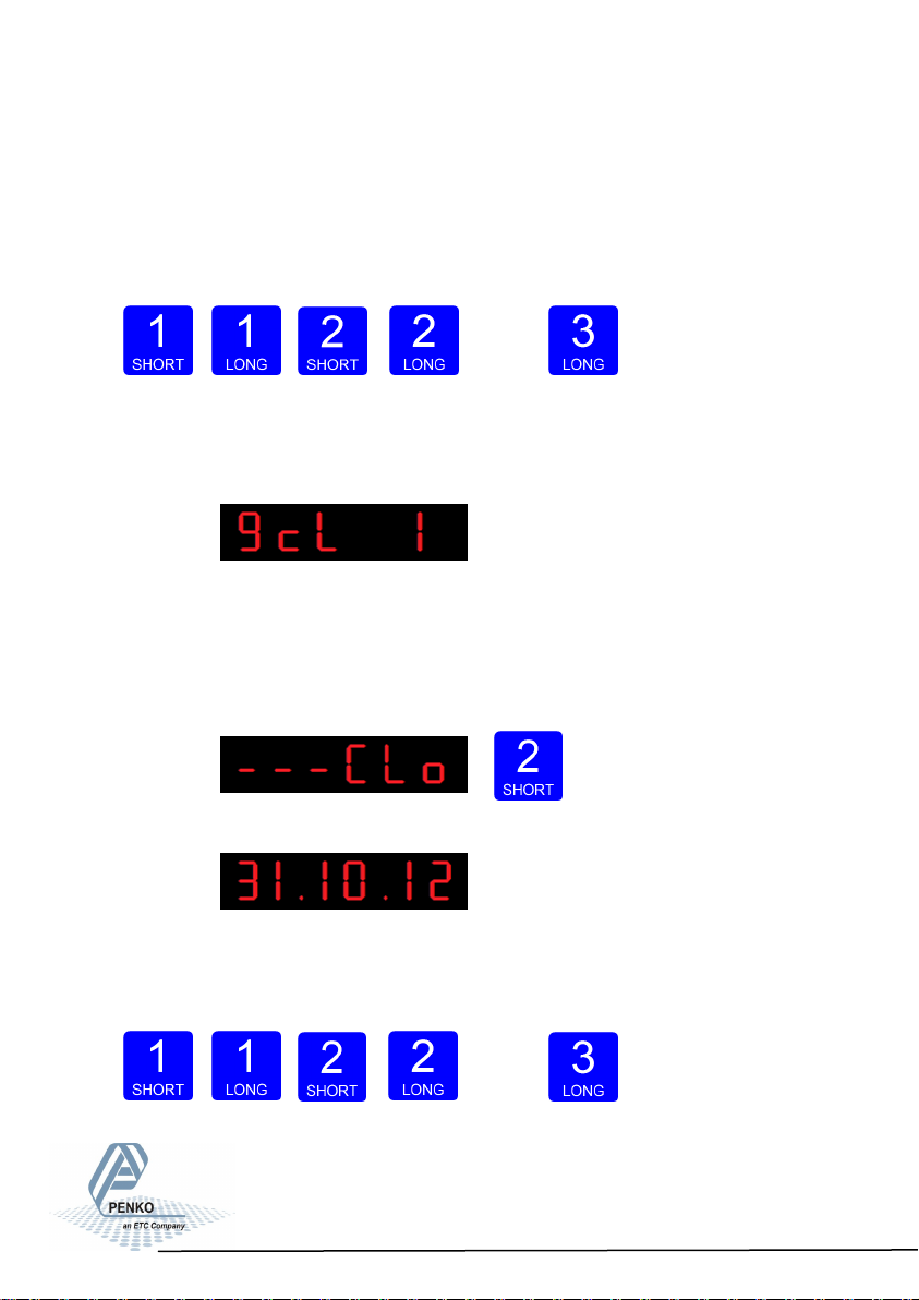
6.15 - - - CLo Date and time configuration (SGM750 only)
In Clock, you can set the internal date and time.
Press key 2 <2 sec to enter Clock.
The following screen is visible:
Set the date. Use key 1 and key 2 to change the number Key 1 is for changing
the number (1-9), key 2 is for changing the position of the cursor. Confirm by
pressing key 3 >2 sec. Format DD.MM.YY
Up Down Left Right Confirm
70
Page 71
SGM700 Digitizer
Configuration Menu -rcl-
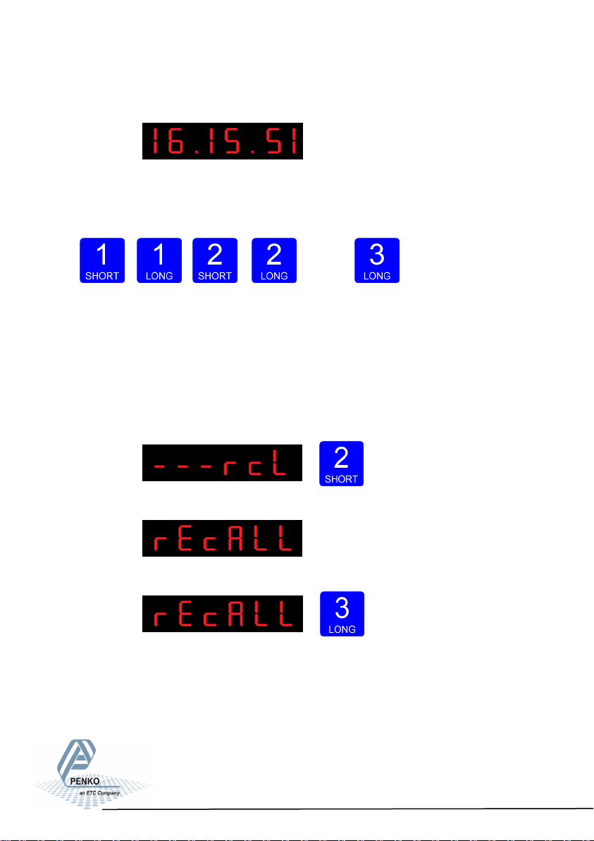
The following screen is visible:
Set the time. Use key 1 and key 2 to change the number Key 1 is for changing
the number (1-9), key 2 is for changing the position of the cursor. Confirm by
pressing key 3 >2 sec. Format HH.MM.SS
Up Down Left Right Confirm
6.16 - - - rcL Recall
In Recall, you can reset all parameters back to facatory settings.
Press key 2 <2 sec to enter Recall.
The following screen is visible:
To set all parameters back to factory settings Press key 3 >2 sec.
71
Page 72
SGM700 Digitizer
Configuration Menu -SoF-
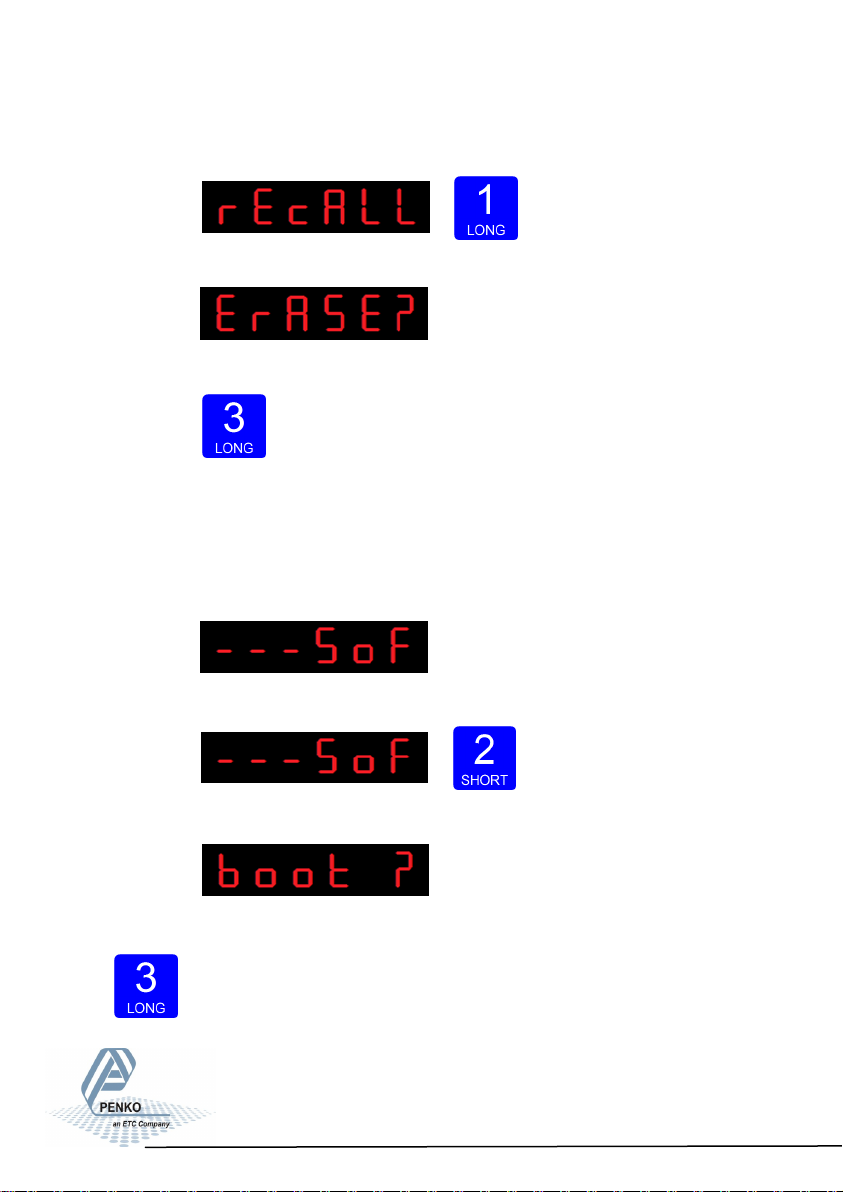
To reset the file system Press key 1 >2 sec.
The following screen is visible:
Confirm by pressing key 3 >2 sec.
The SGM700 will reboot after he file system is reset.
6.17 - - - SoF Firmware update
In SoF, you can set the SGM700 in boot mode for software update.
Press key 2 <2 sec to enter Boot mode.
The following screen is visible:
Press key 3 >2 sec to set the SGM700 in Boot mode.
72
Page 73
SGM700 Digitizer
7. Firmware update
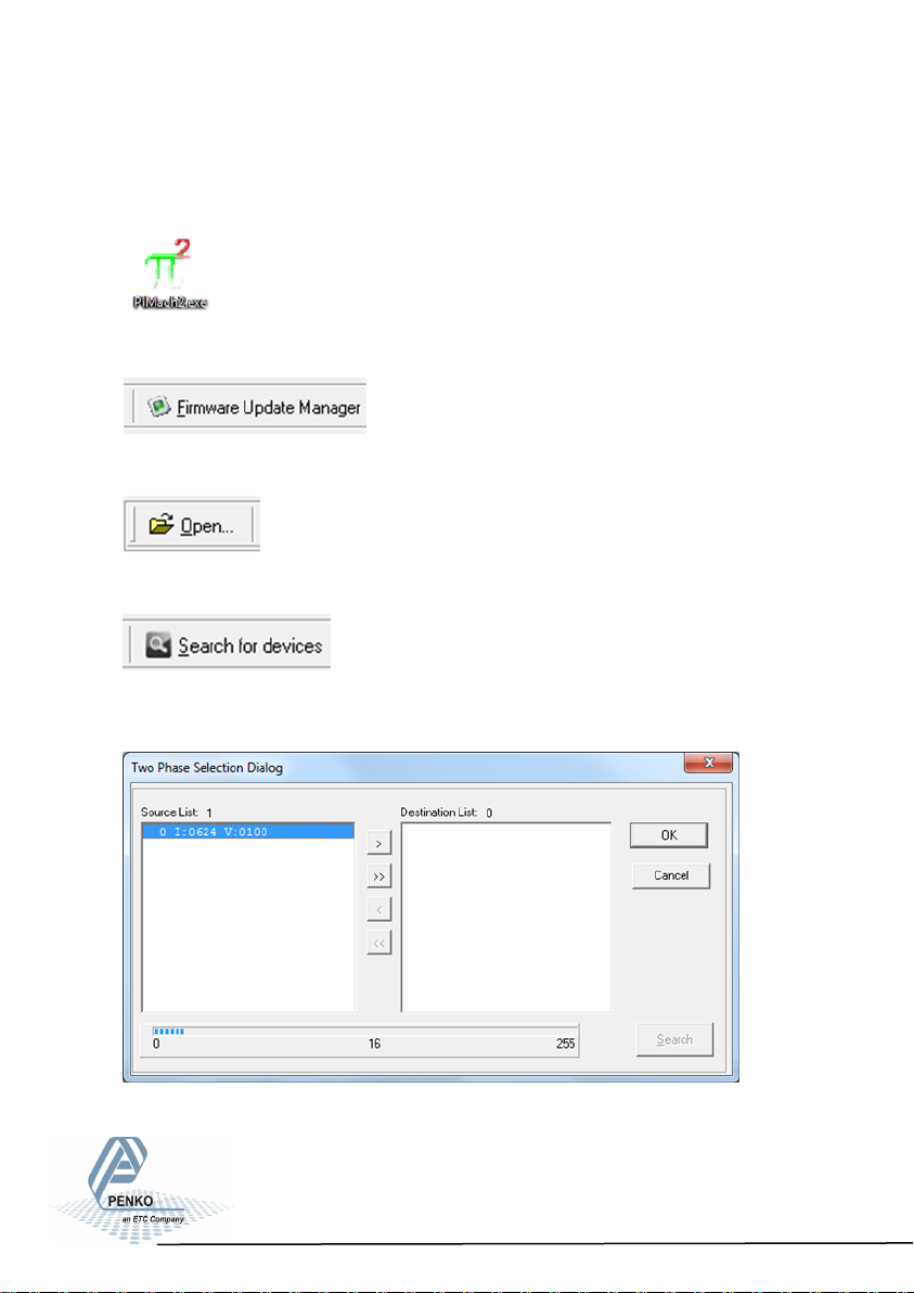
Connect the SGM to the computer through USB. Start PI Mach II. Set communi-
cation to USB.
Start the Firmware Update Manager.
Click Open and select the PIP file.
Click Search For Devices and select the device with source “0”.
Use double click or the arrow button to put the address in the Destination List and
click OK.
73
Page 74
SGM700 Digitizer
Firmware update -continue-
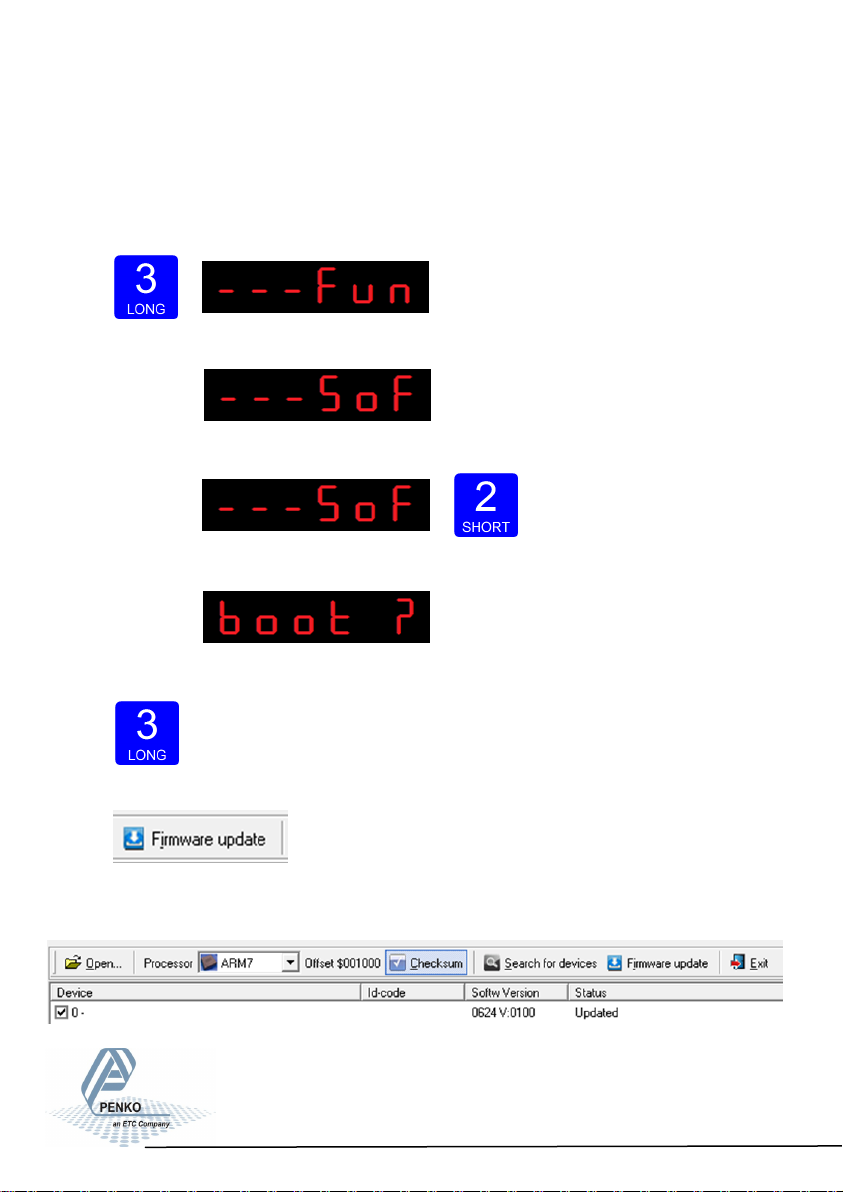
Now set the SGM in boot mode:
Go into the configuration menu by pressing key 3 >2 sec.
The following screen will appear:
Go to- - - SoF by pressing key 1 <2 sec untll you see - - - SoF
Press key 2 <2 sec to enter Boot mode.
The following screen is visible:
Press key 3 >2 sec to set the SGM700 in Boot mode.
Now click Firmware Update to start the update.
The SGM will reboot automatically and the Firmware Update Manager wil show
Updated.
74
Page 75

SGM700 Digitizer
8. Error Codes
Error Code Description Solution
2001 Parameter error Invalid entry, choose a valid value
2005 Input value is not valid Invalid entry, choose value within
2101 Weigher not stable Wait for stable weigher signal and try
2102
2103
2104
2105
2106
2107
2108
2109
2110
2111
2112
2113
2114
2115
2116
Parameter exceeds maxload
Parameter below zero
Not in zero range
Arithmetic overflow occurred
A/D reads all 1’s
A/D reads all 0’s
Gain ref. < zero ref.
Gain > 0.99984741211
Save error
Flash ROM exhausted
Error on header creation
Error on date write
Header validation failed
De-active old data fail
Load errors
Remove load from scale
Check if scale is blocked
Remove load
Change calibration levels
Check load cell connection
Check load cell connection
Change calibration levels
Change calibration levels
Contact PENKO
Contact PENKO
Contact PENKO
Contact PENKO
Contact PENKO
Contact PENKO
Contact PENKO
2117
2118
2119
Item not found in store
Error in stored data
Bad calibration
Contact PENKO
Contact PENKO
Change calibration levels
75
Page 76

SGM700 Digitizer
8.1 Weigher error Codes
Error Code Description Solution
CCCCCC No proper calibration available Check calibration setting
UUUUUU Underflow
OOOOOO Overflow
Display overflow;
======
Exceed maximum display
value (max. load)
Check loadcell
Check platform construction
Check loadcell
Check platform construction
Reduce load on platform
9. ASCII
9.1 ASCII -Protocol Format-
Item Options
Baudrate 1200 / 2400 / 4800 / 9600 / 19k2 / 38k4 / 57k6 / 115k2 bps
Data bits 8-bits
Stop bits 1-bit
Parity NONE
76
Page 77

SGM700 Digitizer
9.2 ACSII -Protocol Commands-
Command Respons strings Operation
OP <number><CR> OK<CR>/ERR<CR> Open channel connection
CL<CR> Close channel connection
SZ<CR> OK<CR>/ERR<CR> Set Zero value
RZ<CR>
ST<CR>
RT<CR>
PT<value><CR>
PS<CR>
RP<CR>
RV<CR>
GD<CR>
GN<CR>
GG<CR>
GP<CR>
GV<CR>
GF<CR>
GS<CR>
GW<CR>
GX<CR>
OK<CR>/ERR<CR>
OK<CR>/ERR<CR>
OK<CR>/ERR<CR>
OK<CR>/ERR<CR>
OK<CR>/ERR<CR>
OK<CR>/ERR<CR>
OK<CR>/ERR<CR>
OK<CR>/ERR<CR>
N+00000<CR>
G+00000<CR>
P+00000<CR>
V+00000<CR>
F+00000<CR>
S+00000<CR>
W+00000+00000SSCC<CR> Get long net+gross, status &
X+00000<CR>
Reset Zero value
Set Tare
Reset Tare
Get/Set Preset Tare
Activate preset Tare
Reset Peak
Reset Valley
Get Display value
Get net
Get gross
Get peak
Get valley
Get fast net (no display damping)
Get A/D sample
checksum
Get extended net (net x 10)
LW<CR>
LF<CR>
W+00000+00000SSCC<CR>/ERR<CR> Get long net+gross, status &
checksum
F+00000+00000SSCC<CR>/ERR<CR>
Get long fast net+gross, status &
77
Page 78
SGM700 Digitizer
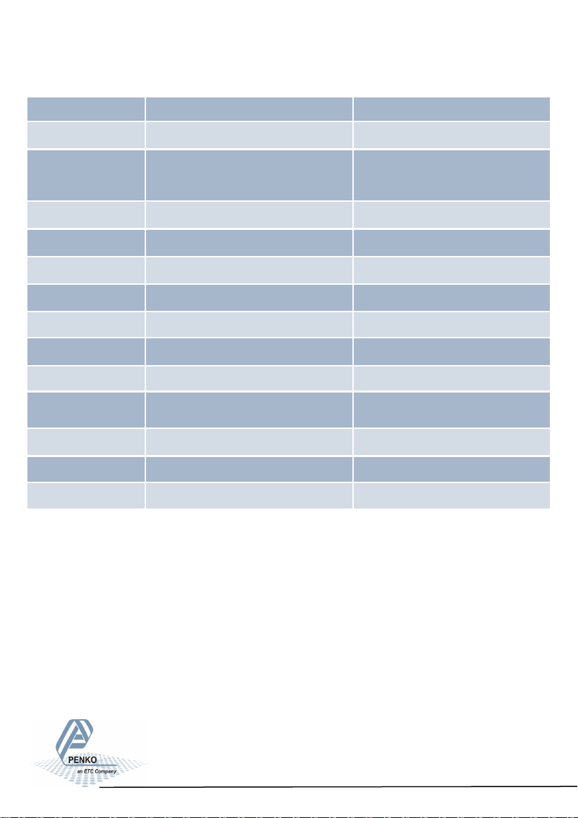
5. ACSII -protocol commands - continue-
Command Respons strings Operation
LN<CR> N+00000+00000SSCC<CR>/ERR<CR> Get net+fast net , status & checksum
Get long extended net (net x 10) +
LX<CR> X+00000+00000SSCC<CR>/ERR<CR>
SD<CR> OK<CR>/ERR<CR> Set auto-transmit display value
SN<CR> OK<CR>/ERR<CR> Set auto-transmit net
SG<CR> OK<CR>/ERR<CR> Set auto-transmit gross
SW<CR> OK<CR>/ERR<CR> Set auto-transmit long weight
SP<CR> OK<CR>/ERR<CR> Set auto-transmit peak
SV<CR> OK<CR>/ERR<CR> Set auto-transmit valley
SF<CR> OK<CR>/ERR<CR> Set auto-transmit fast net
extended gross (gross x 10), status &
checksum
SX<CR> OK<CR>/ERR<CR>
IV<CR> V:0102<CR> Information on Version
ID<CR> D:0502<CR> Information on Device
IS<CR> S:001000<CR> Information on System
Set auto-transmit extended net
(net x 10)
78
Page 79

SGM700 Digitizer
10. Profibus Protocol Description
Module = "weight" 0x28, 0x1E
; gross 32 bits inputs
; net 32 bits inputs
; tare 32 bits inputs
; status 16 bits inputs
; cmd 8 bits inputs
; level1 32 bits outputs
; level2 32 bits outputs
; cmd 8 bits outputs
;
; cmd bit definitation:
; 1 = zero reset command
; 2 = zero set command
; 3 = tare off
; 4 = tare on
; 5 = free
; 6 = free
; 7 = free
; 8 = free
;
; status bit definitation:
; 1 = hardware overload detected
; 2 = overload detected
; 3 = stable signal
; 4 = in stable range
; 5 = zero corrected
; 6 = center of zero
; 7 = in zero range
; 8 = zero tracking posible
; 9 = tare active
; 10 = preset tare active
; 11 = new sample available
; 12 = calibration invalid
; 13 = calibration enabled
; 14 = user certified operation
; 15 = level 1 active
; 16 = level 2 active
EndModule
79
Page 80

SGM700 Digitizer
11. Standard Factory Settings
Description Display Value Your setting
Setpoint function Fun 1 1
Fun 2 1
Fun 3 1
Fun 4 1
Setpoint action Acn 1 000,010
Acn 2 000,010
Acn 3 000,010
Acn 4 000,010
Analog output dAC 4 2
dAC 5 000.000
dAC 6 010.000
dAC 7 4
Local bus communication 485 1 1
Profibus Pb 1 1
Pb 2 FL
Ethernet Adr 1 010
Adr 2 001
Adr 3 002
Adr 4 004
Sub 1 255
Sub 2 255
Sub 3 255
Sub 4 0
80
Page 81
SGM700 Digitizer
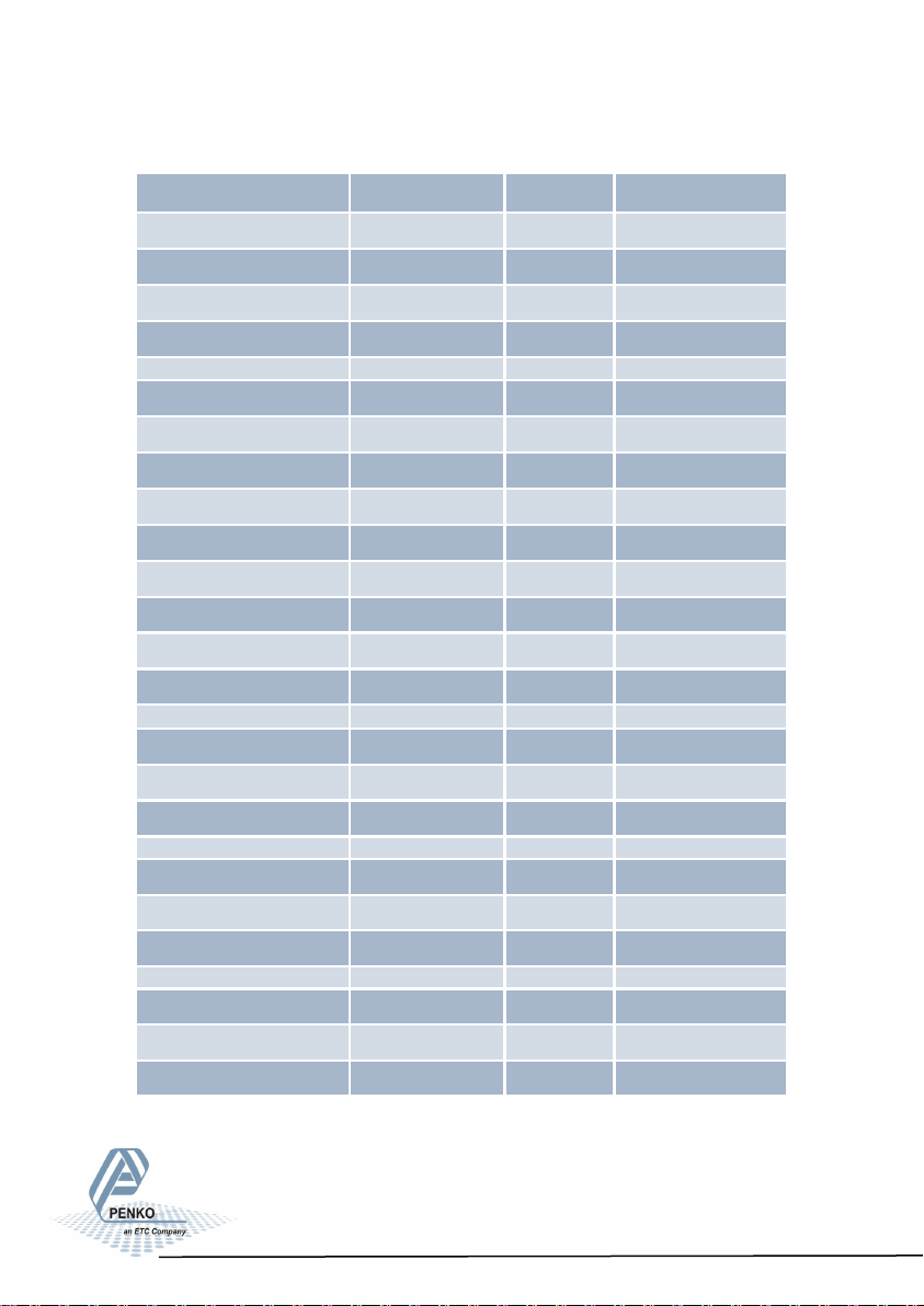
7. Standard Factory Settings -continue-
Description Display Value Your setting
Ethernet gAT 1 0
gAT 2 0
gAT 3 0
gAT 4 0
Indicator Ind 1 10.009
Ind 2 2
Ind 3 1.000
Ind 4 Ind 5 1
Ind 6 - - - . - - Ind 7 25
Ind 8 In
Ind 9 1.60
Multi range/interval Rng 1 0
Rng 2
1
Rng 3 oF
Filter FIL 1 0
FIL 2 FIL 3 0
Digital filter dSF 1 Dynamic
dSF 2 2.5Hz
sSF 3 50
81
Page 82
SGM700 Digitizer
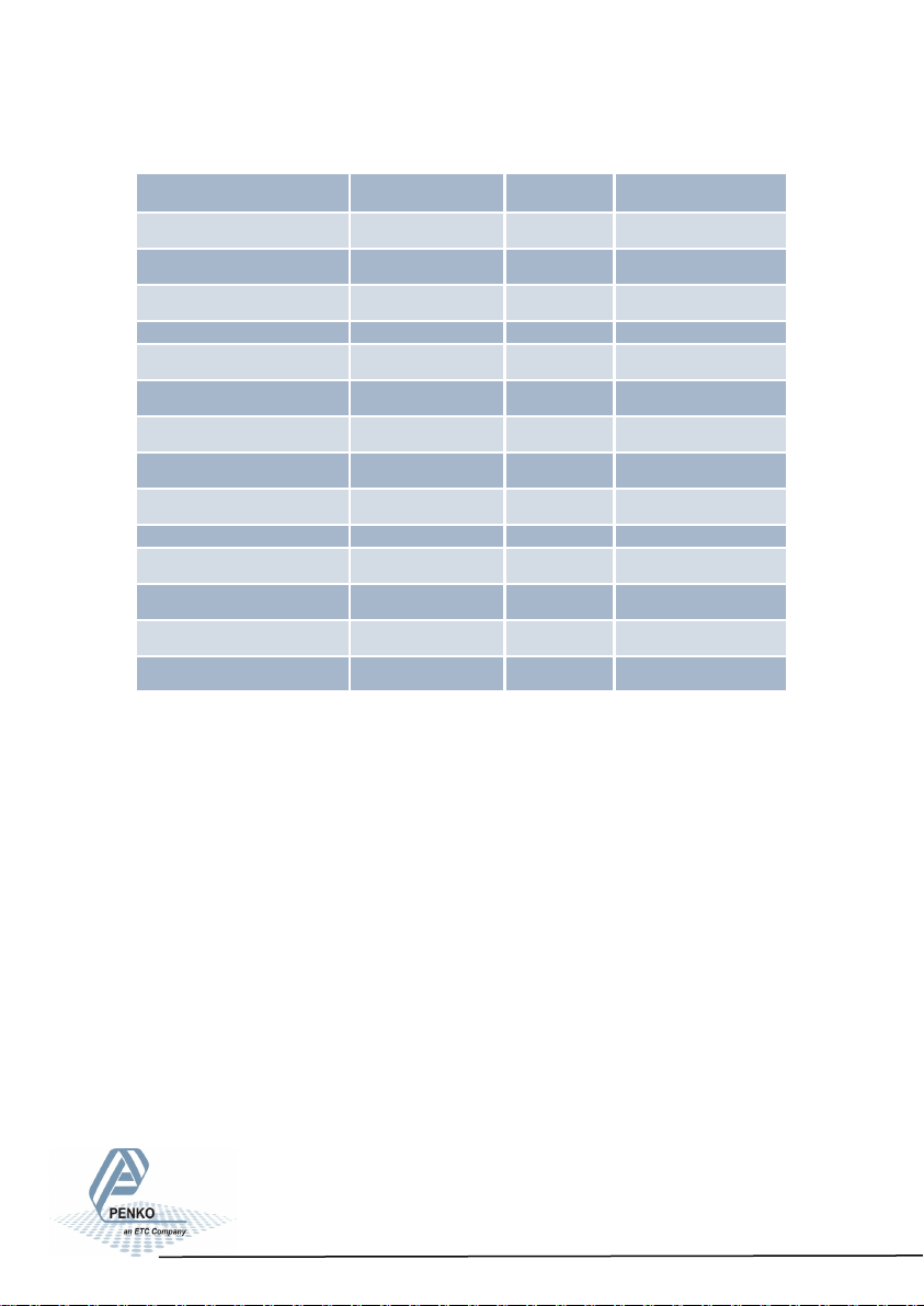
7. Standard Factory Settings -continue-
Description Display Value Your setting
Pre-calibration Pcl 1 un
Pcl 2 2.0
Pcl 3 0
Theoretic calibration tCL 1 10.000
tCL 2 0.000
tCL 3 0.000
tCL 4 0.000
tCL 5 0.000
Geographic calibration gCL 1 52.00
gCL 2 0
gCL 3 52.00
gCL 4 0
82
Page 83

SGM700 Digitizer
Appendix I
Description Definition
Weight filtered net weigher value that can react on mulit range/interval
Fast Gross unfiltered gross weigher value
Fast Net unfiltered net weigher value
Gross filtered gross weigher value
Net filtered net weigher value
Tare tare value
Peak highest reached weigher value can be reset by button peak reset
Valley lowest reached weigher value can be reset by button valley reset
Weight x 10
Fast Gross x 10 unfiltered gross weigher value shown with extra decimal
Fast Net x 10 unfiltered bet weigher value shown with extra decimal
Gross x 10 filtered gross weigher value shown with extra decimal
Net x 10 filtered net weigher value shown with extra decimal
Tare x 10 tare value shown with extra decimal
Peak x 10
Valley x 10
Sample direct value got from the load cell(s)
filtered net weigher value shown with extra decimal that can react
on multi range / multi interval
highest reached weigher value shown with extra decimal can be
reset by button peak reset
lowest reached weigher value shown with extra decimal can be
reset by button valley reset
83
Page 84

SGM700 Digitizer
Our Design expertise includes systems for manufacturing plants, bulk weighing, check
weighing, force measuring and process control. For over 35 years, PENKO Engineering has
been at the forefront of high-accuracy, high-speed weighing systems and our solutions
continue to help cut costs and drive profits for some of the largest global brands, like Cargill,
Sara Lee, Heinz, Kraft Foods and Unilever.
Certification
PENKO products are tested and
certified by independent expert and
overnment organisations to ensure
they meet or exceed metrology
industry guidlines - and our own
high standards - for performance.
A library of our testing certificates is
available for reference at
www.penko.com/publications.
PENKO Engineering B.V. | Schutterweg 35, 6718 XC Ede | The Netherlands | Tel 0031 (0)318 525630 |
Fax 0031 (0)318 529715 | [email protected] | www.penko.com
All product information and specifications are subject to change without prior notice. Copyright © 2012
PENKO. All Rights Reserved. 7600M1042 Updated 11/12
World Wide Dealers
PENKO Dealers Worldwide:
Australia, Brazil, China, Denmark,
Egypt, Finland, France, Germany,
India, Netherlands, Norway,
Portugal, Solvakia, South Africa,
Spain, Sweden, Switzerland,
Syria, Turkey, United Kingdom
For a full list, please visit
www.penko.com
 Loading...