

Page 1
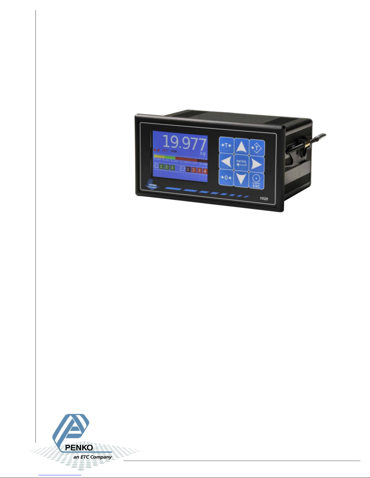
1020 Check Weigher
PENKO Engineering B.V.
Your Partner for Fully Engineered Factory Solutions
Manual:
1020 Supplement Check Weigher Controller
1
Page 2

1020 Check Weigher
Table of Contents
1 Introduction .............................................................................................................................. 3
2 Indication of display .................................................................................................................. 4
3 Configure and control ............................................................................................................... 6
3.1 PENKO configuration software .......................................................................................... 6
3.2 Device ................................................................................................................................ 8
3.3 Industrial protocols .......................................................................................................... 13
4 Parameters .............................................................................................................................. 14
4.1 Configuration parameters ............................................................................................... 14
4.2 Recipe parameters ........................................................................................................... 16
4.3 Live process parameters .................................................................................................. 17
5 Inputs and outputs .................................................................................................................. 18
5.1 Inputs ............................................................................................................................... 18
5.2 Outputs ............................................................................................................................ 18
6 Printer Ticket ........................................................................................................................... 19
7 Program basics ........................................................................................................................ 20
7.1 Static check mode, Reject mode set to Time .................................................................. 20
7.2 Static check mode, Reject mode set to Photocell ........................................................... 20
7.3 Dynamic check mode, Reject mode set to Time ............................................................. 21
8 Default settings ....................................................................................................................... 22
2
Page 3

1020 Check Weigher
1 Introduction
This manual is applicable for the following Check Weigher devices:
• 1020 CHK
• 1020 CAN-RS232-RS422 CHK
• 1020 Profibus CHK
To configure and control the Belt Weigher, the following options are available:
Full control:
• PENKO Pi Mach II software
• PENKO PDI Client software
• Modbus protocol
• Profibus protocol
• EtherNet/IP protocol
• ASCII protocol
Basic control:
• Fins protocol*
• PENKO TP protocol*
* Register functions not available
Note:
This manual does not describe the basic functionality of the device. Consult the device manual
for this.
3
Page 4
1020 Check Weigher
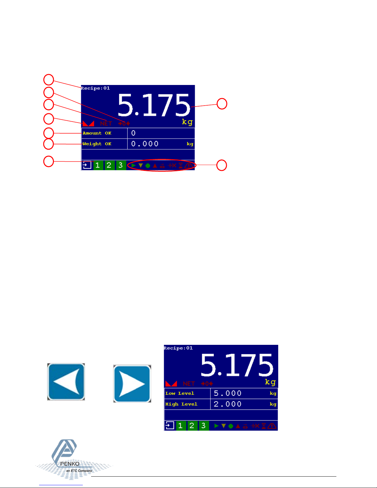
1
Current selected recipe
6
Total correct product weight
2
Zero active
7
Inputs 1, 2, 3
3
Tare active
8
Value
4
Weigher stable
9
Status Indications
5
Total correct product amount
2
3
7
4
8
1
5
6
9
2 Indication of display
nd
Options for indication 2
Use the LEFT or RIGHT key to switch between the four main screens.
nd
The 2
screen shows the flow as the largest indication.
or
screen
4
Page 5
1020 Check Weigher
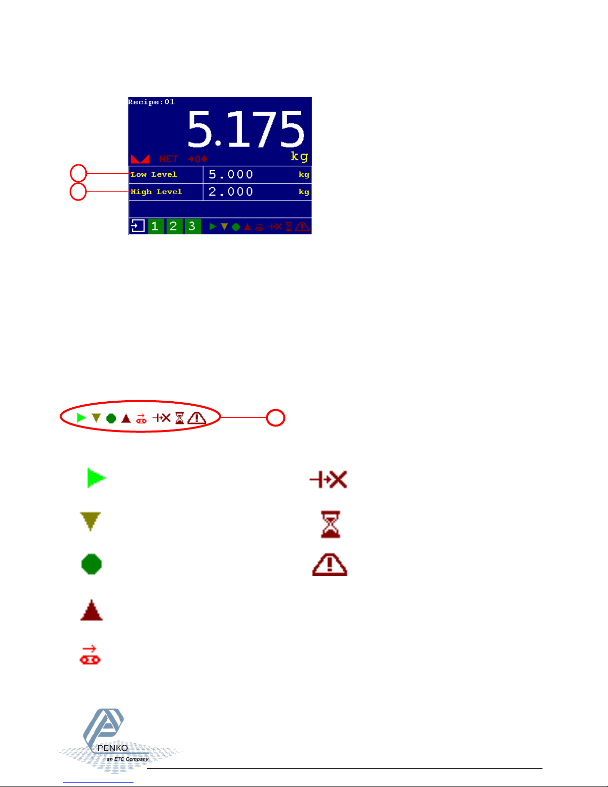
5a
Currently selected low level from
recipe
5b
Currently selected high level from
recipe
Start
Reject – reject output active
Low – last checked value was too
Busy – check weighing in
OK – last checked value was ok
Alarm – alarm output active
High – last checked value was too
Transport – transport belt running
5a
6a
9
Status Indications:
low
high
progress
5
Page 6
1020 Check Weigher
Configuration parameters
3 Configure and control
To configure and control the Check Weigher, the following options are available:
• PENKO configuration software
• Device
• Industrial protocols
3.1 PENKO configuration software
PENKO Pi Mach II and PENKO PDI Client can be downloaded from www.penko.com
USB driver and user manual are included in the download
Pi Mach II supports USB and Ethernet connection. PDI Client is USB only.
Consult the manuals on how to install and connect to the device.
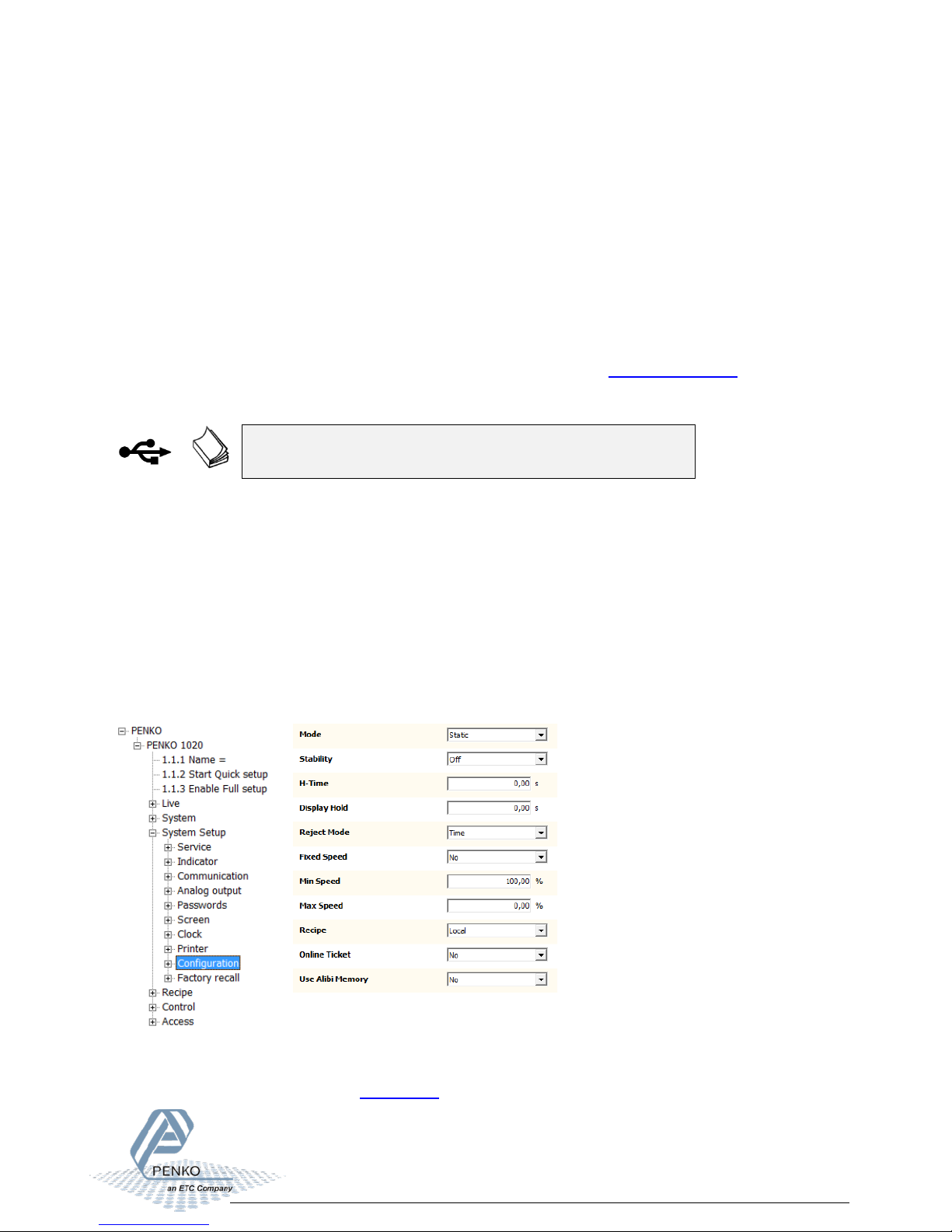
In the tree structure of the device, the configuration parameters are found at:
PENKO - PENKO 1020 - System Setup - Configuration
The parameters are explained in chapters 4
6
Page 7
1020 Check Weigher
Recipe parameters
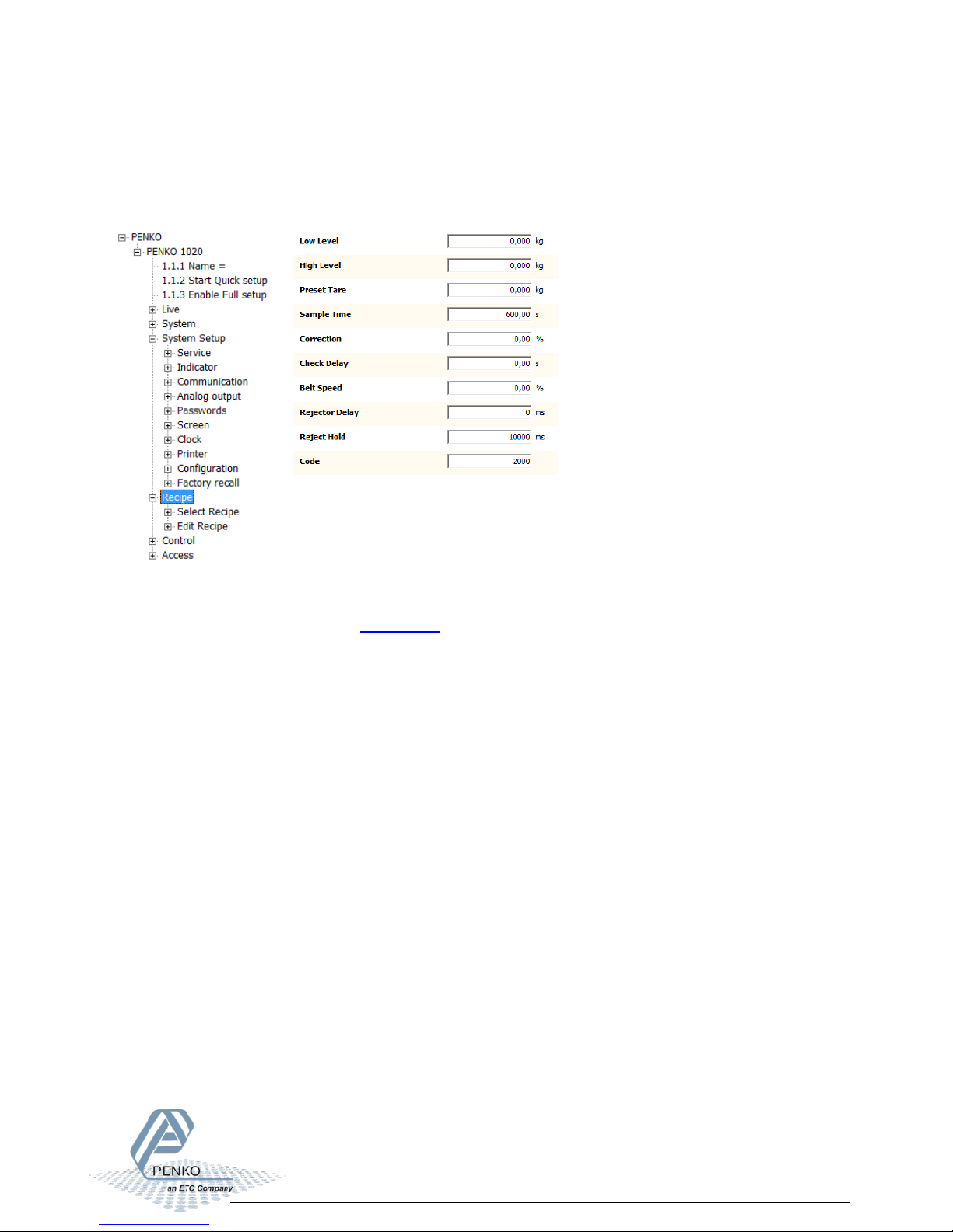
In the tree structure of the device, the recipe parameters are found at:
PENKO - PENKO 1020 - Recipe
The parameters are explained in chapters 4
7
Page 8
1020 Check Weigher
3.2 Device
Configuration
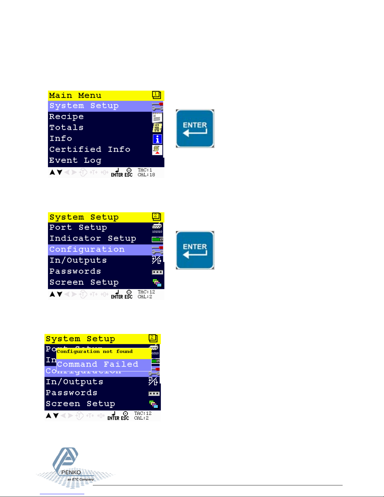
Select System Setup from the Main Menu and press Enter.
Select Configuration from the System Setup Menu and press Enter.
The following error is visible if no configuration is present.
8
Page 9
1020 Check Weigher
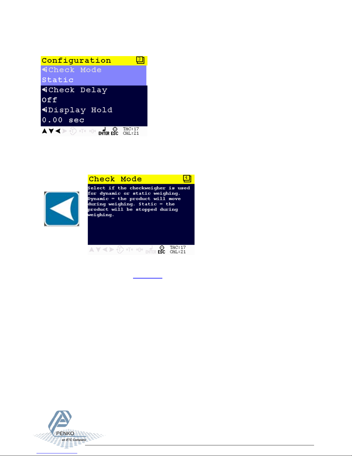
Press Enter to start with default values.
When pushing the LEFT key, the help text of the parameter is shown.
Below the example of a help text for the parameter Check Mode.
The parameters are explained in chapters 4
9
Page 10
1020 Check Weigher
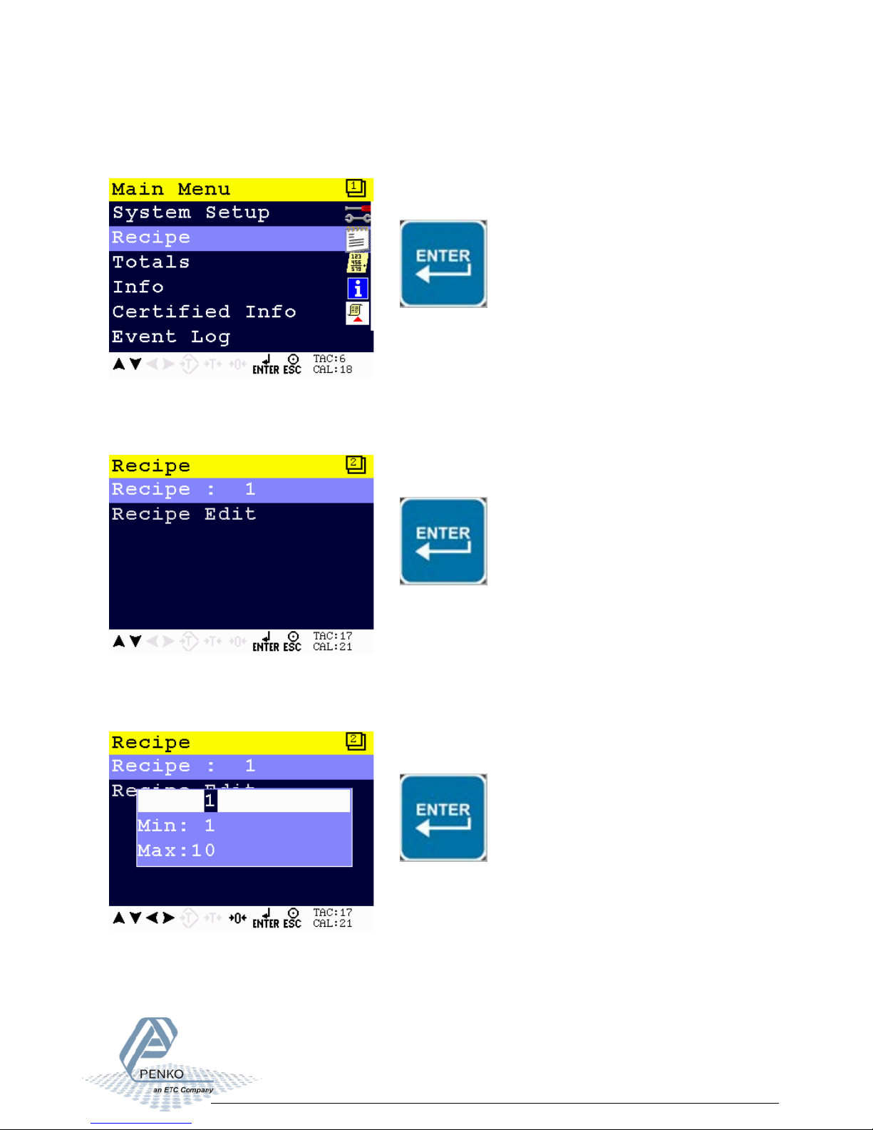
Recipe
Select Recipe from the Main Menu and press Enter.
Select Recipe and press Enter.
Enter the recipe that you want to edit and press Enter.
A maximum of 10 recipes can be stored.
10
Page 11
1020 Check Weigher
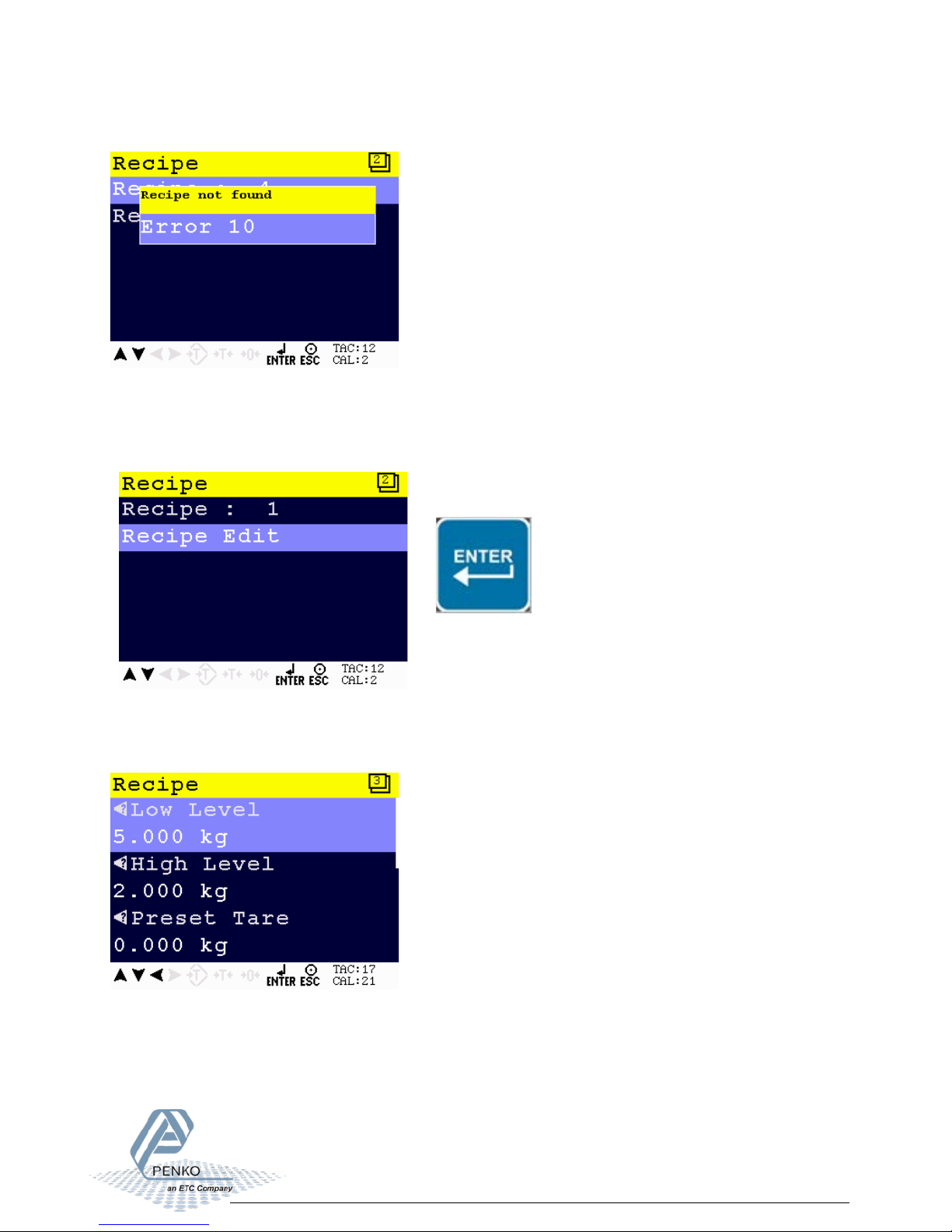
If the selected recipe does not exist, the following error is visible:
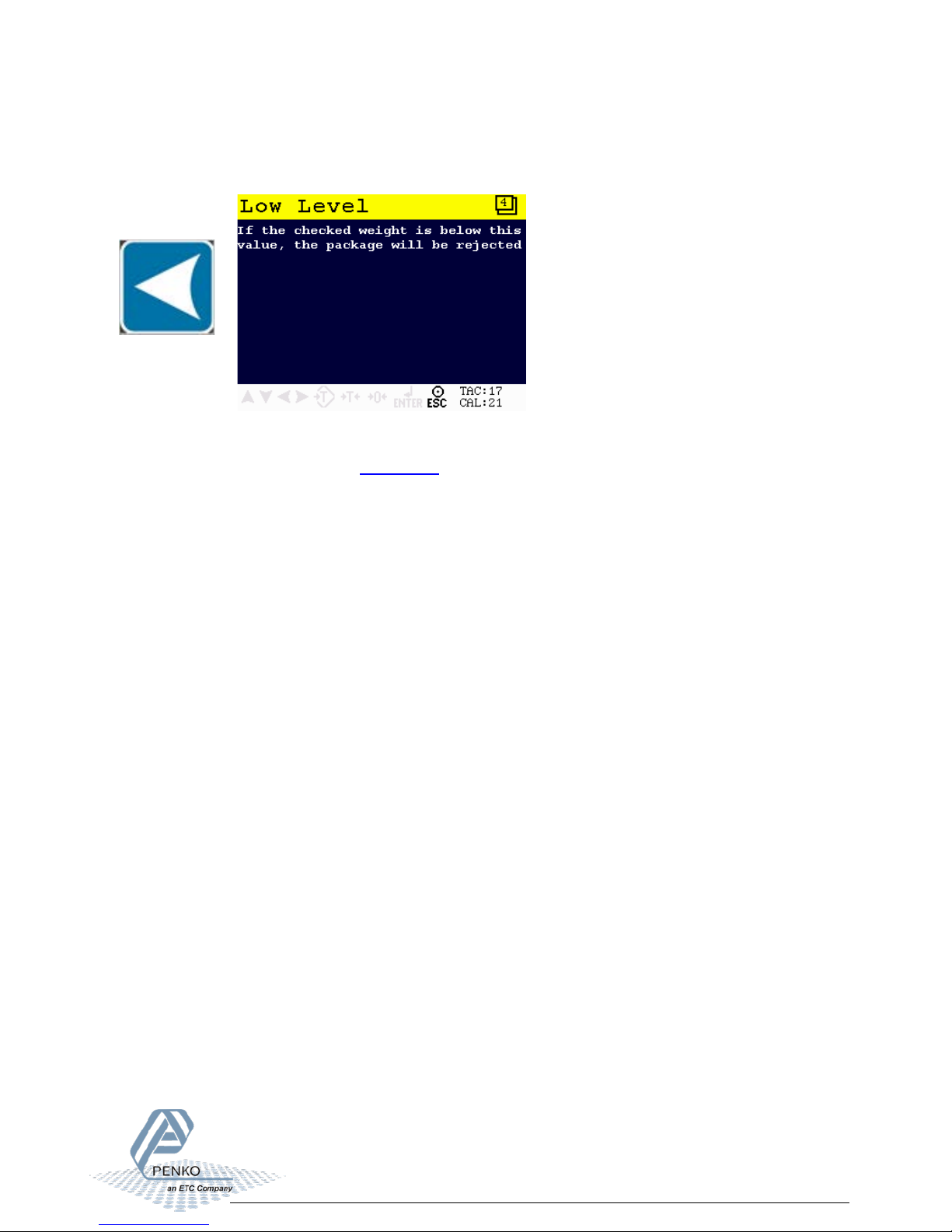
To edit current selected recipe parameters, select Recipe Edit and press Enter.
The following screen is visible:
11
Page 12
1020 Check Weigher
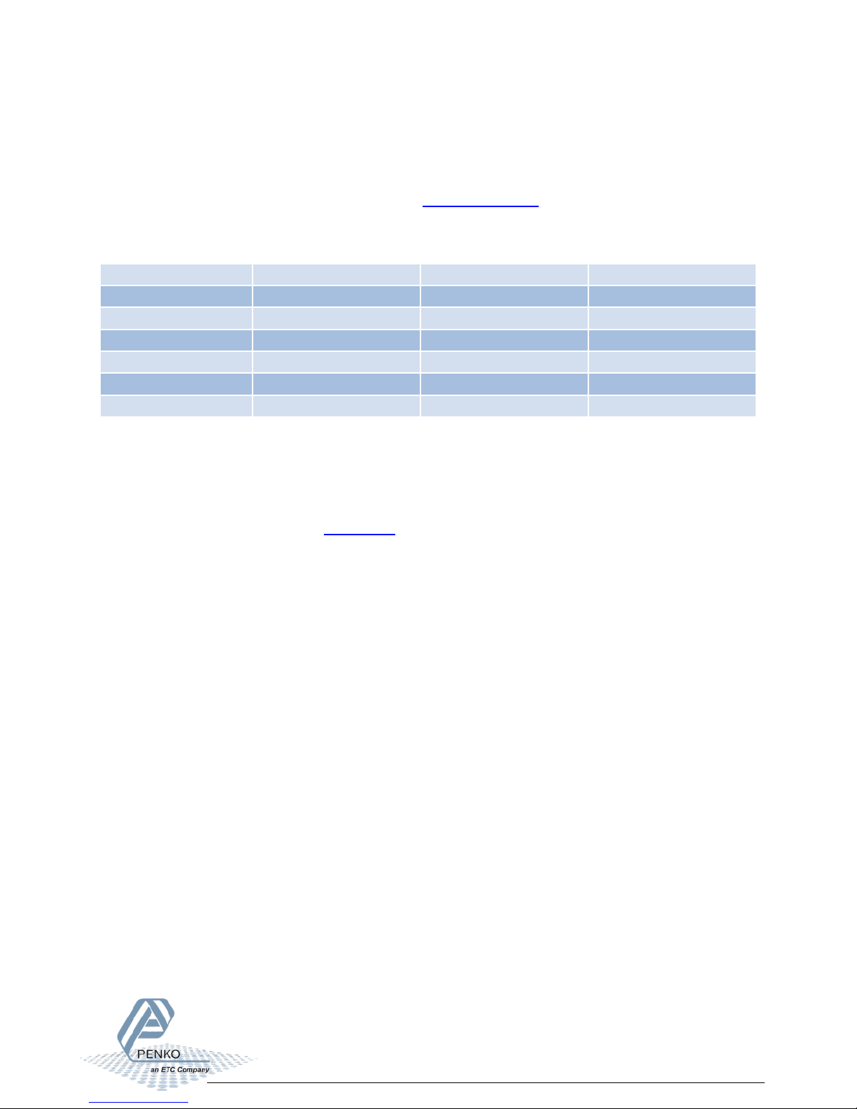
When pushing the LEFT key, the help text of the parameter is accessed.
Below an example of the help text for the parameter Low Level.
The parameters are explained in chapters 4
12
Page 13
1020 Check Weigher
1020
1020 CAN-RS232/422
1020 Profibus
Modbus TCP
Modbus SERIAL
Profibus
EtherNet/IP
ASCII TCP
ASCII SERIAL
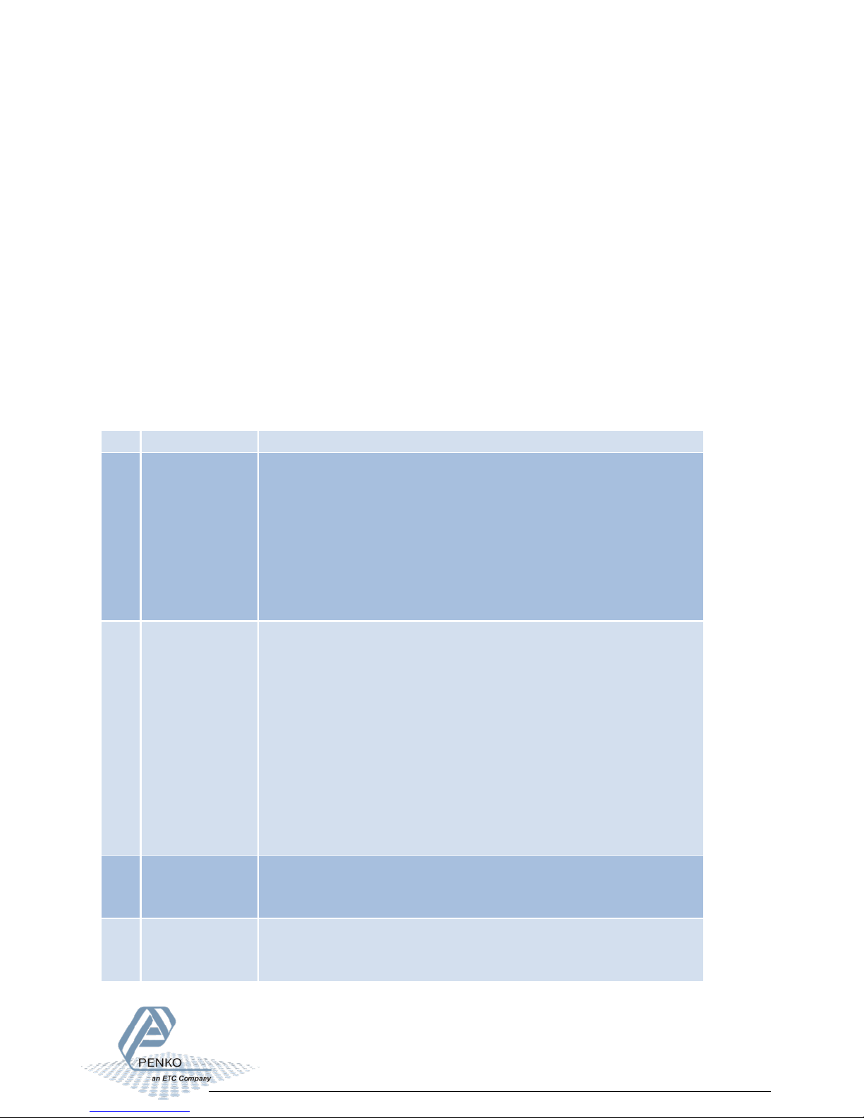
3.3 Industrial protocols
The PENKO protocols Modbus, Profibus, EtherNet/IP and ASCII have a function set called
register functions. These functions allow the user to configure and control the device.
Protocol descriptions can be downloaded from www.penko.com
Consult these on how to connect the device and use the register functions.
Note: the FINS and PENKO TP protocol do not support register functions, only basic read and
write operations for markers and registers.
The parameters are explained in chapters 4
13
Page 14
1020 Check Weigher
No.
Name
Description
1
Check mode
Select if the check weigher is used for dynamic or static
check is done).
2
Stability
Select the type of check delay. In static check mode the belt
Time
3
H-Time
Time to wait for stable weight measurement.
Δ Not used if Stability parameter is set to Off or Stable
4
Display hold
The time to freeze the checked value on the display after the
time is elapsed, the hold time will be cut off.
4 Parameters
These parameters correspond with the parameters in the tree structure of the device Recipe.
When using the industrial protocol register functions, each parameter can be reached using its
number.
Some parameters can be reached directly using ASCII, TP protocol, Modbus RTU, Modbus TCP,
Fins, Profibus or EtherNet/IP. The parameters for Profibus or EtherNet/IP are prefixed with PB
or EIP.
Note: when the device is rebooted or the recipe is manually changed, all recipe parameters are
changed back to the value that were last set manually in the recipe.
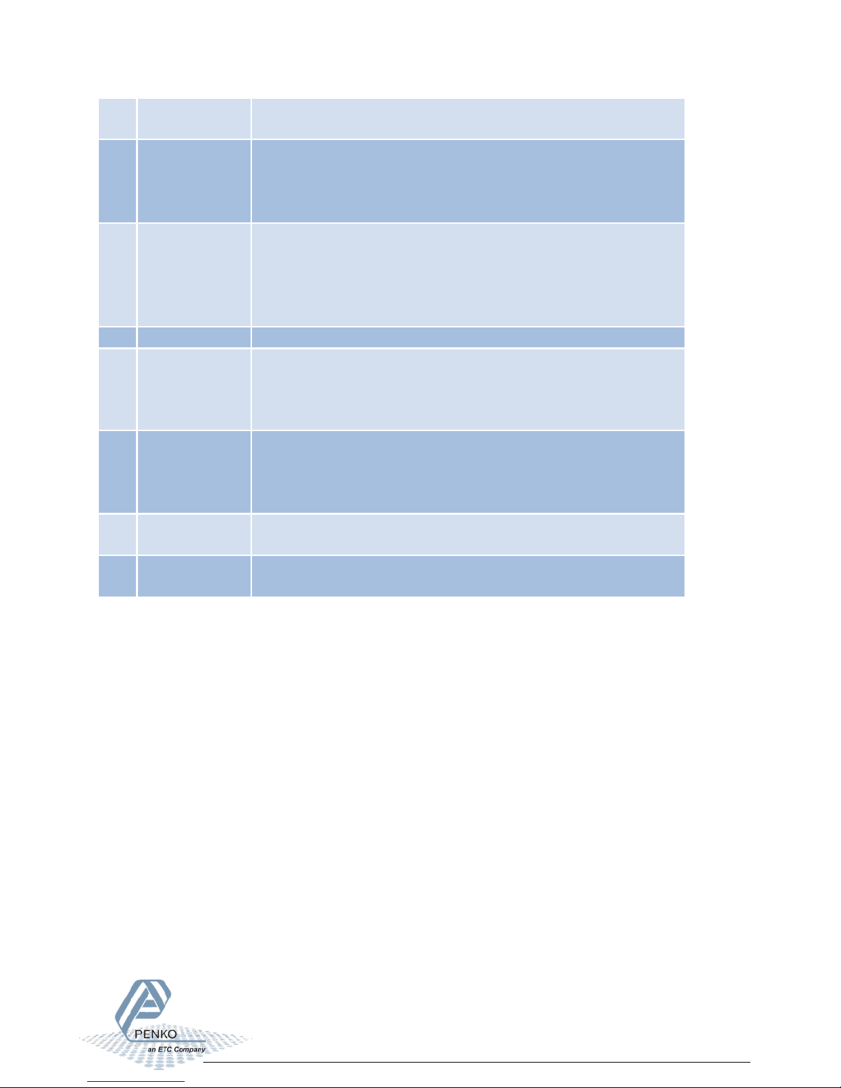
4.1 Configuration parameters
weighing.
• Dynamic => the product will move during weighing (belt is
running).
• Static => the product will be stopped during weighing (belt
is stopped when check input is high and restarted when
will stop during the check delay.
• Off => check starts directly
• Stable => check starts after Stable
• H-Time => check starts after H-time
• H-Time+Stable => check starts after H-time and then
Stable
• H-Time/Stable => check starts after H-time or Stable
• Stable+H-Time => check starts after Stable and then H-
check is done. When a check starts before the display hold
14
Page 15
1020 Check Weigher
Δ Not used if Stability parameter is set to Off or Stable
5
Rejector mode
Select when the packages should be rejected.
Photocell => reject when passing the photocell (input 3)
6
Fixed speed
Select if the belt speed is fixed or variable.
Yes => belt speed is fixed (setting is in recipe)
7
Min. speed
Enter the minimum variable belt speed.
8
Max. speed
Enter the maximum variable belt speed.
9
Recipe
Select the used recipe.
• Remote => use the recipe from a remote device (e.g. PLC)
10
Online ticket
Select if a printer ticket must be printed for each checked
product.
11
Use alibi
memory
Select if a result must be written to the internal alibi memory.
• Time => reject after a set time (settings are in recipe)
•
• No => belt speed is variable between set minimum and
maximum speed and is controlled by the analog output
•
• Local => use the recipe selected on the device
15
Page 16

1020 Check Weigher
No.
Name
Description
Location
1
Low level
If the checked value is below this value, the package will be
rejected.
PB-R85
EIP-R11
2
High level
If the checked value is above this value, the package will be
rejected.
PB-R86
EIP-R2
3
Preset tare
The preset tare will be subtracted from the checked value.
PB-R87
EIP-R13
4
Sample time
Duration of the package weight measurement.
PB-R88
EIP-R14
5
Correction
Correction factor to correct the fault caused by the dynamic
0% to 200%. 100% means no correction is used.
6
Check delay
Enter the time between detecting a product and start
checking or stopping the belt.
7
Belt speed
The speed of the transport belt in %
8
Rejector delay
Delay time to activate the rejector after detecting a faulty
package.
9
Reject hold
Time to hold the rejector output active for a certain time
after activating.
10
Batch code
Enter a Batch code for printing reports.
4.2 Recipe parameters
These parameters correspond with the parameters in the tree structure of the device Recipe.
When using the industrial protocol register functions, each parameter can be reached using its
number.
Some parameters can be reached directly using ASCII, TP protocol, Modbus RTU, Modbus TCP,
Fins, Profibus or EtherNet/IP. The parameters for Profibus or EtherNet/IP are prefixed with PB
or EIP.
Note: when the device is rebooted or the recipe is manually changed, all recipe parameters are
changed back to the value that were last set manually in the recipe.
characteristics of the machine. Correction can be set from
16
Page 17
1020 Check Weigher
No.
Name
Description
Marker
1
Low level
Get the low level value.
M401
2
High level
Get the high level value.
M402
3
Subtotal
std.dev
Get the standard deviation of the
subtotal.
M403
4
Subtotal
average
Get the average value of the subtotal.
M404
5
Subtotal
(weight) ok
Get the weight of the accepted
products of the subtotal.
M405
6
Subtotal
count ok
Get the number of accepted product
of the subtotal.
M406
7
Subtotal
count low
Get the number of too low product of
the subtotal.
M407
8
Subtotal
count high
Get the number of too high product of
the subtotal.
M410
9
Subtotal
count total
Get the number of all product of the
subtotal.
M411
10
Total
std.dev
Get the standard deviation of the total
batch.
M412
11
Total
average
Get the average value of the total
batch.
M414
12
total
(weight) ok
Get the weight of the accepted
products of the total batch.
M415
13
Total count
ok
Get the number of accepted product
of the total batch.
M416
14
Total count
low
Get the number of too low product of
the total batch.
M417
15
Total count
high
Get the number of too high product of
the total batch.
Marker
16
total count
total
Get the number of all product of the
total batch.
M401
17
Alibi no.
Get the number of the Alibi record.
M402
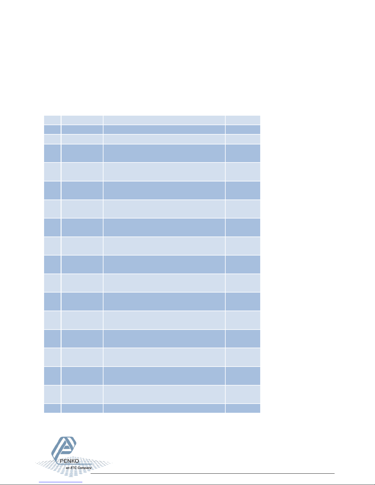
4.3 Live process parameters
When using the industrial protocol register functions, each parameter can be read using its
number.
Example: to read the value of low level, Use the function code 701 and value 1.
17
Page 18
1020 Check Weigher
Input
Name
Description
Profibus
marker
EtherNet/IP
marker
1
Start/Stop
Input must be high to set the program in
run mode.
969
433
2
Start
Sampling
Input to start sampling the package.
970
434
3
Reject
Input to detect the package on the reject
over the belt.
971
435
Output
Name
Description
1
Rejector
Output to enable the rejector after the package is detected on
the reject position.
2
Sampling Busy
Output to enable the busy output.
Output is high from detecting the package until sampling is done.
3
Transport Belts
Output to enable the transport belts.
indicator alarm.
4
Alarm
Output to enable the indicator alarm.
This alarm can be reset by switching off input 1.
Analog
out
Belt Speed
Belt Speed will be available from 0.00% to 100.00%.
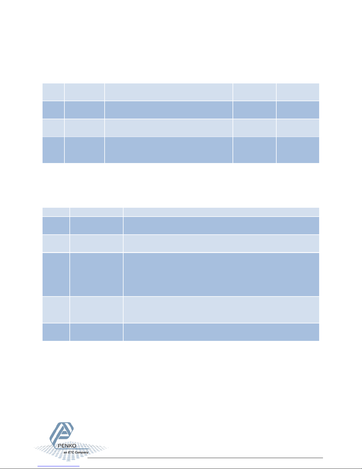
5 Inputs and outputs
The following inputs and outputs are used.
5.1 Inputs
Sensor
5.2 Outputs
position. Input must be placed diagonal
In dynamic mode the output is always on if no alarm is
generated.
In static mode the output is off during sampling and during an
This output is used to activate the indicator alarm.
18
Page 19

1020 Check Weigher
Programmable header 1
Programmable header 2
Programmable header 3
Programmable header 4
11
TIME 05:57.13
001
TICKET NUMBER 100
CHECKED NET 00000.00 kg
Programmable footer 1
Programmable footer 2
6 Printer Ticket
Example of the 1020 Printer recipe when ‘Ticket’ layout is selected.
------------------------------------
---
DATE 07-10-
RECIPE
------------------------------------
---
19
Page 20

1020 Check Weigher
7 Program basics
This chapter describes a few basics of the Check Weigher program which can be used when
starting the program for the first time.
7.1 Static check mode, Reject mode set to Time
With input 1 you can Start (input high) and Stop (input low) the program. The Transport Belt
(output 3) will start. With a pulse on Start Sampling (input 2) the checking will start. During
checking the Transport Belt (output 3) will stop and Sample Busy (output 2) is on.
When the checking is complete and the weight is ok, the Transport belt (output 3) will start
again, Sample Busy (output 2) is off. With a pulse on Start Sampling (input 2) the checking will
start again.
If the weight is below Low Level or above High Level the Transport belt (output3) will start
again. After the Reject Delay time, the Rejector (output 1) will turn on, and will remain on for
the duration of the Reject Hold time. With a pulse on Start Sampling (input 2) the checking will
start again.
7.2 Static check mode, Reject mode set to Photocell
With input 1 you can Start (input high) and Stop (input low) the program. The Transport Belt
(output 3) will start. With a pulse on Start Sampling (input 2) the checking will start. During
checking the Transport Belt (output 3) will stop and Sample Busy (output 2) is on.
When the checking is complete and the weight is ok, the Transport belt (output 3) will start
again, Sample Busy (output 2) is off. With a pulse on Start Sampling (input 2) the checking will
start again.
If the weight is below Low Level or above High Level the Transport belt (output3) will start
again. When the photocell (connected to input 3) has detected the product, the Rejector
(output 1) will turn on, and will remain on as long as input 3 (photocell) in on. With a pulse on
Start Sampling (input 2) the checking will start again.
20
Page 21
1020 Check Weigher
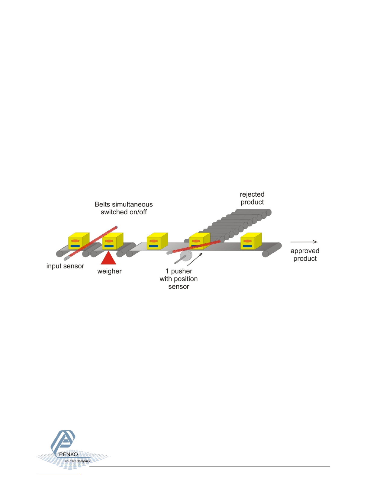
7.3 Dynamic check mode, Reject mode set to Time
With input 1 you can Start (input high) and Stop (input low) the program. The Transport Belt
(output 3) will start. With a pulse on Start Sampling (input 2) the checking will start. During the
checking the Sample Busy (output 2) is on.
When the checking is complete and the weight is ok. The Transport belt (output 3) will start
again, Sample Busy (output 2) is off. With a pulse on Start Sampling (input 2) the checking will
start again.
If the weight is below Low Level or above High Level the Transport belt (output3) will start
again. After the Reject Delay time, the Rejector (output 1) will turn on, and will remain on for
the duration of the Reject Hold time. With a pulse on Start Sampling (input 2) the checking will
start again.
21
Page 22
1020 Check Weigher
Configuration
Static check
Static check
Dynamic check
Check Mode
Static
Static
Dynamic
Stability
Stable + H-Time
Stable + H-Time
Stable + H-Time
H-Time
1.00 sec
1.00 sec
1.00 sec
Display Hold
1.00 sec
1.00 sec
1.00 sec
Rejector Mode
Time
Photocell
Time
Fixed Speed
Yes Yes Yes
Min. Speed
0.00%
0.00%
0.00%
Max. Speed
100.00%
100.00%
100.00%
Recipe
Local
Local
Local
Online Ticket
No No No
Use Alibi Memory
No No No
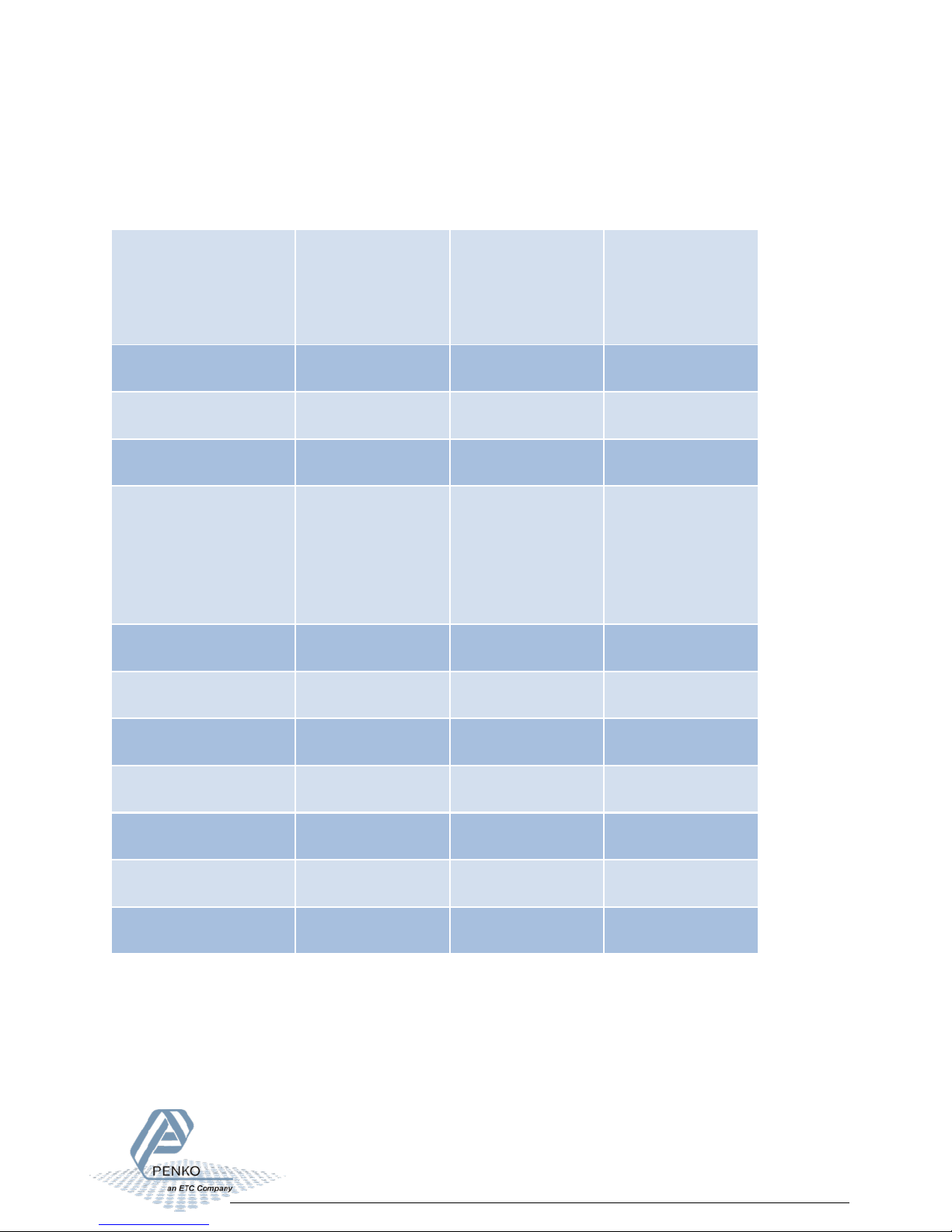
8 Default settings
Configuration:
(Disabled if stability
parameter is set to
off or stable)
mode, Reject
mode set to Time
mode, Reject
mode set to
Photocell
mode, Reject
mode set to Time
22
Page 23
1020 Check Weigher
DAC setup
Setting
Indicator
Speed
Min
0.00%
Max
100.00%
Mode
4 – 20 mA
Weigher
Setting
Unit Label
Kg Step
1 Decimal point
0.00
Operation Mode
Industrial
Max Load
1000.00
Stable Condition
Setting
Range
0.10 kg
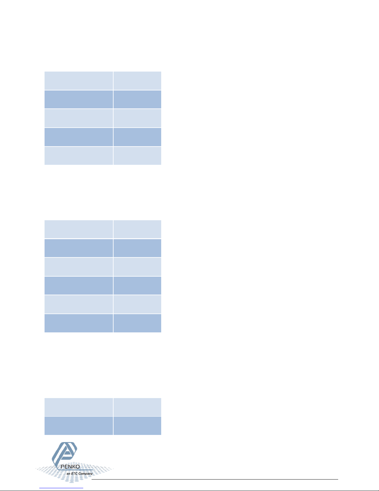
To access the DAC setup, select In/Outputs from the System Setup Menu and press Enter.
Select DAC Setup and press Enter. If you don’t have the DAC output, In/Outputs is not available.
To access the Weigher setup, select Indicator Setup from the System Setup Menu and press
Enter. Select Indicator and press Enter, enter the TAC code (the TAC code is visible in the
bottom right corner of the LCD screen) and press Enter. Select Weigher and press Enter.
To access the Stable Condition setup, select Indicator Setup from the System Setup Menu and
press Enter. Select Indicator and press Enter, enter the TAC code (the TAC code is visible in the
bottom right corner of the LCD screen) and press Enter. Select Stable Condition and press
Enter.
23
Page 24

1020 Check Weigher
Time
0.50 sec
Filter Digital
Setting
Digital Filter
Dynamic
Cutoff Frequency
1.0 Hz
Frequency
10 Hz
To access the Stable Condition setup, select Indicator Setup from the System Setup Menu and
press Enter. Select Indicator and press Enter, enter the TAC code (the TAC code is visible in the
bottom right corner of the LCD screen) and press Enter. Select Filter and press Enter. Select
Digital and press Enter.
App.
24
Page 25
1020 Check Weigher
About PENKO
Whether you are looking for a simple stand-alone weighing system or a high-speed weighing and dosing controller for a complex
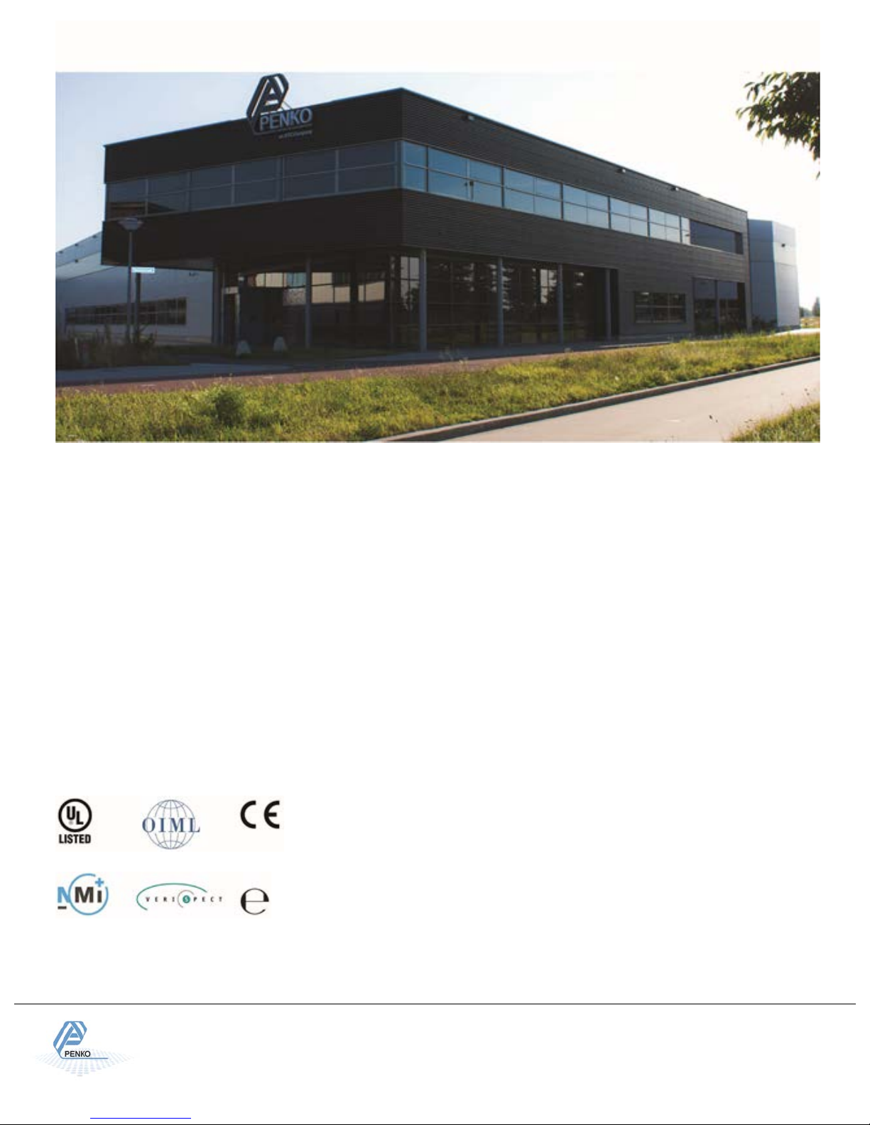
Certifications
PENKO sets high standards for its products and product
independent expert and government organizations to
PENKO Professional Services
PENKO is committed to ensuring every system is installed, tested,
Our engineers, at our weighing center in Ede, Netherlands, as well as
classes to anyone interested in exploring modern,
Belgium, Brazil, China,
Denmark, Germany, Egypt, Finland, France, India, Italy, Netherlands,
Norway, Poland, Portugal, Slovakia, Spain, Syria, Turkey, United
PENKO Engineering B.V. ▪ Schutterweg 35, NL 6718XC Ede ▪ Tel +31 (0) 318525630 ▪ Fax +31 (0) 318529715▪ [email protected]
Our design expertise include systems for manufacturing plants, bulk weighing, check weighing, force measuring and process control.
For over 35 years, PENKO Engineering B.V. has been at the forefront of development and production of high-accuracy, high-speed
weighing systems and our solutions continue to help cut costs, increase ROI and drive profits for some of the largest global brands,
such as Cargill, Sara Lee, Heinz, Kraft Foods and Unilever to name but a few.
automated production line, PENKO has a comprehensive range of standard solutions you can rely on.
performance which are tested, certified and approved by
ensure they meet – and even – exceed metrology industry
guidelines. A library of testing certificates is available for
reference on:
http://penko.com/nl/publications_certificates.html
programmed, commissioned and operational to client specifications.
our distributors around the world, strive to solve most weighingsystem issues within the same day. On a monthly basis PENKO offers
free training
high-speed weighing instruments and solutions. A schedule of training
sessions is found on: www.penko.com/training
PENKO Alliances
PENKO’s worldwide network: Australia,
Kingdom, South Africa, Slovakia Sweden and Switzerland, Singapore.
A complete overview you will find on: www.penko.com/dealers
Web ▪ www.penko.com ▪ Copyright © 2014 ETC All rights reserved 7600M105-EN-R5 1020 MANUAL SUPPLEMENT CHK.
25
 Loading...