


1U Server Chassis
User Manual
(SCSI)
Mar. 2005 (Revision A,6)
P/N: 1230B0001801

CCooppyyrriigghhtt NNoottiiccee
© 2004-2005 Inventec Enterprise System Corporation (IESC). All rights reserved.
All product names or brands mentioned herein are the trademarks of IESC or their respective owners.

CCoonntteennttss
About This Manual ........................................................................................................................................i
Conventions..................................................................................................................................................i
Package Contents .........................................................................................................................................i
Standard Components...............................................................................................................................i
Optional Components...............................................................................................................................i
Safety Precautions.......................................................................................................................................ii
Operation Safety......................................................................................................................................ii
Electrical Safety......................................................................................................................................ii
Tools Required .......................................................................................................................................iii
Regulatory and Integration Information.....................................................................................................iv
Regulatory Compliance Identification Numbers....................................................................................iv
Product Regulatory Compliance ............................................................................................................iv
Battery Replacement Notice...................................................................................................................vi
Power Cords..........................................................................................................................................vii
1 Product Introduction .........................................................................................................................1-1
1.1 Product Features...........................................................................................................................1-1
1.2 System Overview .........................................................................................................................1-3
1.2.1 Server Chassis Layout..........................................................................................................1-3
1.2.2 Front View............................................................................................................................1-4
1.2.3 Power Button and System LEDs..........................................................................................1-4
1.2.4 Back View ............................................................................................................................1-6
2 Hardware Operation..........................................................................................................................2-1
2.1 Before You Start...........................................................................................................................2-1
2.1.1 Power Off.............................................................................................................................2-1
2.2 Chassis Cover...............................................................................................................................2-2
2.3 Motherboard.................................................................................................................................2-5
2.4 Power Supply ...............................................................................................................................2-7
2.5 System Fans..................................................................................................................................2-8
2.6 Backplane for SCSI HDD ..........................................................................................................2-10
2.7 HDDs..........................................................................................................................................2-12
2.8 CD-ROM....................................................................................................................................2-14
2.9 Front Panel .................................................................................................................................2-16
2.10 Riser Card Assembly..................................................................................................................2-17
3 Cables and Server Installation..........................................................................................................3-1
3.1 Connecting Cables........................................................................................................................3-1
3.1.1 Front Panel Cables................................................................................................................3-1
3.1.2 Power Cables........................................................................................................................3-2
3.1.3 CD-ROM Cables............................................................................................................
......3-3
3.1.4 SCSI HDD Cable..................................................................................................................3-4

3.1.5 Backplane Power Cable........................................................................................................3-4
3.1.6 I2C Signal Cable...................................................................................................................3-5
3.1.7 System Fan Cables ...............................................................................................................3-6
3.2 Cable Vent Baffle .........................................................................................................................3-8
3.3 Power Supply ...............................................................................................................................3-9
3.4 Server Installation ......................................................................................................................3-10
3.5 Power On................................................................................................................... .................3-12
LLiisstt ooff FFiigguurreess
Figure 1-1 Product Introduction........................................................................................................1-1
Figure 1-2 Server Chassis Layout.....................................................................................................1-3
Figure 1-3 Front View .......................................................................................................................1-4
Figure 1-4 Power Button and System LEDs.....................................................................................1-4
Figure 1-5 Back View........................................................................................................................1-6
Figure 1-6 NIC LED .........................................................................................................................1-6
Figure 2-1 Pressing the power button................................................................................................2-1
Figure 2-2 Disconnecting the power cord.........................................................................................2-2
Figure 2-3 Sliding the front top cover to the front ............................................................................2-2
Figure 2-4 Securing the front top cover ............................................................................................2-2
Figure 2-5 Sliding the rear top cover to the front..............................................................................2-3
Figure 2-6 Tightening screws on the top...........................................................................................2-3
Figure 2-7 Removing the rear top cover............................................................................................2-4
Figure 2-8 Loosing the screws ..........................................................................................................2-4
Figure 2-9 Sliding the front top cover out of the chassis...................................................................2-4
Figure 2-10 Motherboard Location...................................................................................................2-5
Figure 2-11 Installing the motherboard.............................................................................................2-6
Figure 2-12 Power Supply Location .................................................................................................2-7
Figure 2-13 Putting the power supply right into the place ................................................................2-7
Figure 2-14 Securing the power supply.............................................................................................2-7
Figure 2-15 System Fans Location....................................................................................................2-8
Figure 2-16 Putting the system fans into the chassis.........................................................................2-8
Figure 2-17 Fixing the system fan.....................................................................................................2-9
Figure 2-18 Backplane for SCSI .....................................................................................................2-10
Figure 2-19 Pressing down the backplane.......................................................................................2-10
Figure 2-20 Fixing the backplane....................................................................................................2-11
Figure 2-21 HDD Assembly Location.............................................................................................2-12
Figure 2-22 Locating the HDD to the HDD tray.............................................................................2-12
Figure 2-23 Inserting the HDD assembly into the bay....................................................................2-13
Figure 2-24 Pushing the lever back in place ................................................................................... 2-13
Figure 2-25 Releasing the lever from the HDD ..............................................................................2-13
Figure 2-26 Sliding the HDD assembly out of the HDD bay..........................................................2-14
Figure 2-27 CD-ROM Location......................................................................................................2-14

Figure 2-28 Fixing the CD-ROM daughter card to the CD-ROM ..................................................2-14
Figure 2-29 Locating the CD-ROM into the place..........................................................................2-15
Figure 2-30 Fixing the CD-ROM with screws................................................................................2-15
Figure 2-31 Front panel Location....................................................................................................2-16
Figure 2-32 Inserting the front panel to the slot..............................................................................2-16
Figure 2-33 Fixing the front panel ..................................................................................................2-16
Figure 2-34 Riser Card Assembly Location....................................................................................2-17
Figure 2-35 Riser Card....................................................................................................................2-17
Figure 2-36 Securing the PCI-X riser card with screws..................................................................2-17
Figure 2-37 Inserting the expansion card to the slot .......................................................................2-18
Figure 2-38 Pressing down the riser card assembly........................................................................2-18
Figure 2-39 Lifting the riser card assembly out of the chassis........................................................2-18
Figure 3-1 Connecting the front panel cable to the motherboard ......................................................3-1
Figure 3-2 Connecting the front panel cable to the front panel.........................................................3-1
Figure 3-3 Connecting the front panel USB cable to the motherboard.............................................3-2
Figure 3-4 Connecting the front panel USB cable to the front panel................................................3-2
Figure 3-5 Connecting the main power cable and processor power cable ........................................3-2
Figure 3-6 Connecting the CD-ROM cable to the motherboard .......................................................3-3
Figure 3-7 Connecting the CD-ROM cable to the CD-ROM............................................................3-3
Figure 3-8 Connecting the CD-ROM power cable............................................................................3-3
Figure 3-9 Connecting the SCSI HDD cable to the SCSI daughter card ..........................................3-4
Figure 3-10 Connecting the SCSI HDD cable to the backplane .......................................................3-4
Figure 3-11 Connecting the backplane power cable..........................................................................3-4
Figure 3-12 Connecting the I
2
C signal cable to the motherboard .....................................................3-5
Figure 3-13 Connecting the I
2
C signal cable to the backplane..........................................................3-5
Figure 3-14 Connecting the system fan cables..................................................................................3-6
Figure 3-15 Connecting the system fan tach cable to the motherboard ............................................3-6
Figure 3-16 Connecting the system fan tach cable to the backplane.................................................3-6
Figure 3-17 Connecting the system fan power cable to the motherboard.........................................3-7
Figure 3-18 Connecting the system fan power cable to the backplane .............................................3-7
Figure 3-21 Putting the cable vent baffle onto the system fan bracket..............................................3-8
Figure 3-19 Power Supply Assembly................................................................................................3-9
Figure 3-20 Tightening the screws on the rack rail.........................................................................3-10
Figure 3-21 Attaching the two rails.................................................................................................3-10
Figure 3-22 Inserting the server into the rack .................................................................................3-11
Figure 3-23 Connect Cables for Power On .....................................................................................3-12
Figure 3-24 Pressing the power button............................................................................................3-13
LLiisstt ooff TTaabblleess
Table 1-1 Front Panel LED Information ...........................................................................................1-5
Table 1-2 NIC LED Information.......................................................................................................1-6

You are reading the Server user
manual. This manual provides
general and specific information
about this server.
About This Manual
About This Manual

1230B0001801 About This Manual
i
AAbboouutt TThhiiss MMaannuuaall
CCoonnvveennttiioonnss
To make sure that you perform certain tasks properly, take note of the following symbols used
throughout this manual.
Warning:
Information to prevent injury to yourself when trying to complete a task.
Caution:
Information to prevent damage to the components when trying to complete
a task.
Important:
Information that you must follow to complete a task.
Note:
Tips and information to aid in completing a task.
PPaacckkaaggee CCoonntteennttss
This section lists the items included in the server package.
Standard Components
;
1U Server System
;
Rail Kits
;
One Power Cord
;
One Speedy-In!
®
CD
Optional Components
PCI-X Riser Card

1230B0001801 About This Manual
ii
SSaaffeettyy PPrreeccaauuttiioonnss
Observe the following safety precautions when you are connecting or disconnecting any device.
Operation Safety
Important
• Any operation on this server must be conducted by certified or experienced engineers.
• Before operating your server, carefully read all the manuals included with the server package.
• Before using the server, make sure all cables are correctly connected and the power cables are not
damaged. If any damage is detected, contact your dealer as soon as possible.
• To avoid short circuits, keep paper clips, screws, and staples away from connectors, slots, sockets
and circuitry.
• Before opening the chassis panels, make sure all power cables are unplugged.
• Avoid dust, humidity, and temperature extremes; place the server on a stable surface.
• If the power supply is broken, do not try to fix it by yourself. Contact an authorized dealer.
• It is recommended that you wear gloves when assembling or dissembling the server to protect
from cuts and scrapes.
• When the server is powered on, heat sinks and the surfaces of certain IC devices may be hot. Do
not touch them. Check whether the fans are functioning properly.
Electrical Safety
Important
• Before installing or removing signal cables, ensure that the power cables for the system unit and
all attached devices are unplugged.
• To prevent electric shock hazard, disconnect the power cable from the electrical outlet before
relocating the system.
• When adding or removing any additional device to or from the system, ensure that the power
cables for the devices are unplugged before the signal cables are connected. If possible,
disconnect all power cables from the existing system before you add a device.
• Use on hand, when possible, to connect or disconnect signal cables to prevent a possible shock
from touching two surfaces with different electrical potentials.

1230B0001801 About This Manual
iii
Caution
• This product is equipped with a three-wire power cable and plug for user’s safety. Use the power
cable with a properly grounded electrical outlet to avoid electric shock.
Important
Motherboards, adapters, and disk drives are sensitive to static electricity discharge. These devices are
wrapped in antistatic bags to prevent this damage. Take the following precautions:
• If you have an antistatic wrist strap available, use it while handling the device.
• Do not remove the device from the antistatic bag until you are ready to install the device in the
system unit.
• With the device still in its antistatic bag, touch it to a metal frame of the system.
• Grasp cards and boards by the edges. Hold drives by the frame. Avoid touching the solder joints
or pins.
• If you need to lay the device down while it is out of the antistatic bag. Lay it on the antistatic bag.
Before picking it up again, touch the antistatic bag and the metal frame of the system unit at the
same time.
• Handle the devices carefully to prevent permanent damage.
Tools Required
You need a cross screwdriver or a flat screwdriver to install or remove the components in the server.

1230B0001801 About This Manual
iv
RReegguullaattoorryy aanndd IInntteeggrraattiioonn IInnffoorrmmaattiioonn
Regulatory Compliance Identification Numbers
For the purpose of regulatory compliance certifications and identification, this server is assigned a
series number. This server series number can be found on the product label, along with the required
approval markings and information. When requesting certification information for this product,
always refer to this series number. This series number should not be confused with the marketing
name or model number.
Product Regulatory Compliance
Product Safety Compliance
This server complies with the following safety requirements:
• IEC 60950-1 Safety of Information Technology Equipment
• EN 60950-1 Safety of Information Technology Equipment Including Electrical Business
Equipment, European Committee for Electrotechnical Standardization
(CENELEC)
• UL 60950-1 Safety of Information Technology Equipment
• UL 94 Tests for Flammability of Plastic Materials for Parts in Devices & Appliances.
• GB4943 Safety of Information Technology Equipment
Worldwide Safety approvals can be supplied according to the requirements from Marketing or
Customer.
Product EMC Compliance
This product has been tested and verified to comply with the following electromagnetic compatibility
(EMC) regulations.
Communications Commission Notice
Part 15 of the Federal Communications Commission (FCC) Rules and Regulations has established
Radio Frequency (RF) emission limits to provide an interference-free radio frequency spectrum.
Many electronic devices, including computers, generate RF energy incidental to their intended
function and are, therefore, covered by these rules. These rules place computers and related peripheral
devices into two classes, A and B, depending upon their intended installation. Class A devices are
those that may reasonably be expected to be installed in a business or commercial environment. Class
B devices are those that may reasonably be expected to be installed in a residential environment
(personal computers, for example). The FCC requires devices in both classes to bear a label indicating
the interference potential of the device as well as additional operating instructions for the user.
The rating label on the device shows which class (A or B) the equipment falls into. Class A devices do
not have an FCC logo or FCC ID on the label. Class B devices have an FCC logo or FCC ID on the
label. Once the class of the device is determined, refer to the following corresponding statement.

1230B0001801 About This Manual
v
Class B Equipment
This equipment has been tested and found to comply with the limits for a Class B digital device,
pursuant to Part 15 of the FCC Rules. These limits are designed to provide reasonable protection
against harmful interference in a residential installation. This equipment generates, uses, and can
radiate radio frequency energy and, if not installed and used in accordance with the instructions, may
cause harmful interference to radio communications.
However, there is no guarantee that interference will not occur in a particular installation. If this
equipment does cause harmful interference to radio or television reception, which can be determined
by turning the equipment off and on, the user is encouraged to try to correct the interference by one or
more of the following measures:
• Reorient or relocate the receiving antenna.
• Increase the separation between the equipment and receiver.
• Connect the equipment into an outlet on a circuit different from that to which the receiver is
connected.
• Consult the dealer or an experienced radio or television technician for help.
Declaration of Conformity for Products Marked with the FCC Logo—United States Only
This device complies with Part 15 of the FCC Rules Operation and is subject to the following two
conditions: (1) this device may not cause harmful interference, and (2) this device must accept any
interference received, including interference that may cause undesired operation.
For questions regarding your product,
please contact the supplier.
To identify this product, refer to the Part, Series, or Model number found on the product.
European Union Notice
Products with the CE Marking comply with both the EMC Directive (89/336/EEC) and the
Low-Voltage Directive (73/23/EEC) issued by the Commission of the European Community.
Compliance with these directives implies conformity to the following European Norms (in brackets
are the equivalent international standards):
• EN55022 (CISPR 22) — Electromagnetic Interference
• EN55024 (IEC61000-4-2,3,4,5,6,8,11) — Electromagnetic Immunity
• EN61000-3-2 (IEC61000-3-2) — Power Line Harmonics
• EN61000-3-3 (IEC61000-3-3) — Power Line Flicker
• EN60950 (IEC950) — Product Safety
1230B0001801 About This Manual
vi
Canadian Notice (Avis Canadien)
Class B Equipment
This Class B digital apparatus meets all requirements of the Canadian Interference-Causing
Equipment Regulations.
Cet appareil numérique de la classe B respecte toutes les exigences du Règlement sur le matériel
brouilleur du Canada.
Japanese Notice
Taiwanese Notice
Battery Replacement Notice
This server is provided with an internal Lithium battery or battery pack. There is a danger of
explosion and risk of personal injury if the battery is incorrectly replaced or mistreated.
For more information about battery replacement or proper disposal, contact an authorized reseller or
your authorized service provider.
Warning: This server contains an internal Lithium Manganese Dioxide, or a Vanadium
Pentoxide, or an alkaline battery pack. There is risk of fire and burns if the battery pack
is not handled properly. To reduce the risk of personal injury:
• Do not attempt to recharge the battery.
• Do not expose to temperatures higher than 60°C.
• Do not disassemble, crush, puncture, short external contacts, or dispose of in fire or
water.
• Replace only with the spare parts designated for this product.

1230B0001801 About This Manual
vii
Batteries should not be littered with the general household waste. Please use the public
collection system or return them to the supplier.
Power Cords
The power cord set included in the server meets the requirements for use in the country where the
server was purchased. If this server is to be used in another country, purchase a power cord that is
approved for use in that country.
The power cord must be rated for the product and for the voltage and current marked on the product's
electrical ratings label. The voltage and current rating of the cord should be greater than the voltage
and current rating marked on the product. In addition, the cross-sectional area of the wires must be a
minimum of 1.00 mm² or 18 AWG, and the length of the cords must be between 1.8 m (6 feet) and 3.6
m (12 feet). If you have questions about the type of power cord to use, contact an authorized service
provider.
Caution: Route power cords so that they will not be walked on or pinched by items
placed upon or against them. Pay particular attention to the plug, electrical outlet, and the
point where the cords exit from the product.

Product Introduction
This chapter describes the features of
this server. It includes spe cifications and
system overview.
Chapter 1
Product Introduction

1230B0001801 Product Introduction
1-1
11 PPrroodduucctt IInnttrroodduuccttiioonn
This chapter describes the external features of this server. It includes specific sections that identify
these features and specifications. The whole picture of this server is shown as below.
Figure 1-1 Product Introduction
11..11
PPrroodduucctt FFeeaattuurrees
s
The server board is configured for the motherboard that uses Intel
®
E7520 MCH, Intel® ICH5R and
Intel
®
6700PXH chipset. The motherboard supports dual Intel® Xeon™ processors 2.8GHz up to
3.6GHz with 800 MHz FSB processor to accelerate even the most complicated server tasks. The
following highlights are the server’s main features. For additional information, refer to this user
manual.
• Chassis: 1U form factor that fits in a 19” rack.
• Power: 500W single power supply equipped with universal AC input that includes PFC and SSI
compliant output cables.
• Storage: Support four Hard Disk Drive (HDD) bays in removable trays
and one slim CD-ROM .
• Backplane: Support 4 hard drives.
• Processor: Dual Intel
®
Xeon™ processors 2.8GHz up to 3.6GHz with 800 MHz Front Side Bus.
• Memory: 8 DIMM sockets support 400MHz DDR2 (up to 16GB) with ECC support and Dual
Channel low profile (1.2”) Memory for interleaving.
• Onboard LAN: Two RJ45 ports use Broadcom 5721 controllers that support 10/100/1000Mbps.
• Onboard VGA: ATI Rage XL Graphics display chip with 8MB display RAM (SDRAM).

1230B0001801 Product Introduction
1-2
• Integrated Super I/O: Winbond W83627HF controller that supports one serial port, one PS/2
keyboard port, and one PS/2 mouse port.
• Expansion Slot: One full-length 64bit/133MHz PCI-X slot for riser card or other expansion
card.

1230B0001801 Product Introduction
1-3
11..22 SSyysstteemm OOvveerrvviieeww
1.2.1 Server Chassis Layout
Figure 1-2 Server Chassis Layout
Motherboard HDD Bays
Fan Duct Slim CD-ROM
Fan Module Riser Card Board Assembly
Backplane Power Supply
Front Panel

1230B0001801 Product Introduction
1-4
1.2.2 Front View
The front view of this server allows easy access to Hot-Swap HDDs.
The power button, USB ports and system LED indicators are also located on the front panel.
Figure 1-3 Front View
Slim CD-ROM HDD 1 Bay
HDD LED HDD 2 Bay
Front Panel HDD 3 Bay
HDD 0 Bay
1.2.3 Power Button and System LEDs
The front panel on the chassis includes system LEDs to indicate NIC link status and system power
status.
Figure 1-4 Power Button and System LEDs
2 USB Ports Power LED
NIC2 LED UID Button
NIC1 LED Power Button
UID LED

1230B0001801 Product Introduction
1-5
LED Information
Front panel status LEDs allow constant monitoring of basic system functions while the server is
operating.
LED Color Status
On (Steady) Power on
Blinking System is in power saving state
Power Green
Off Power off
On (Steady) 1Gbps link Amber
Blinking 1Gbps Activity
On (Steady) 10/100Mbps Link
Blinking 10/100Mbps Activity
NIC
Green
Off No LAN cable link
On (Steady) By server management software or UID
switch to indicate needing service
Blinking By server management software to
indicate under service
UID Blue
Off By server management software
Table 1-1 Front Panel LED Information
Note: Only BMC server board supports UID function; the server board without BMC
doesn't support UID function.
1230B0001801 Product Introduction
1-6
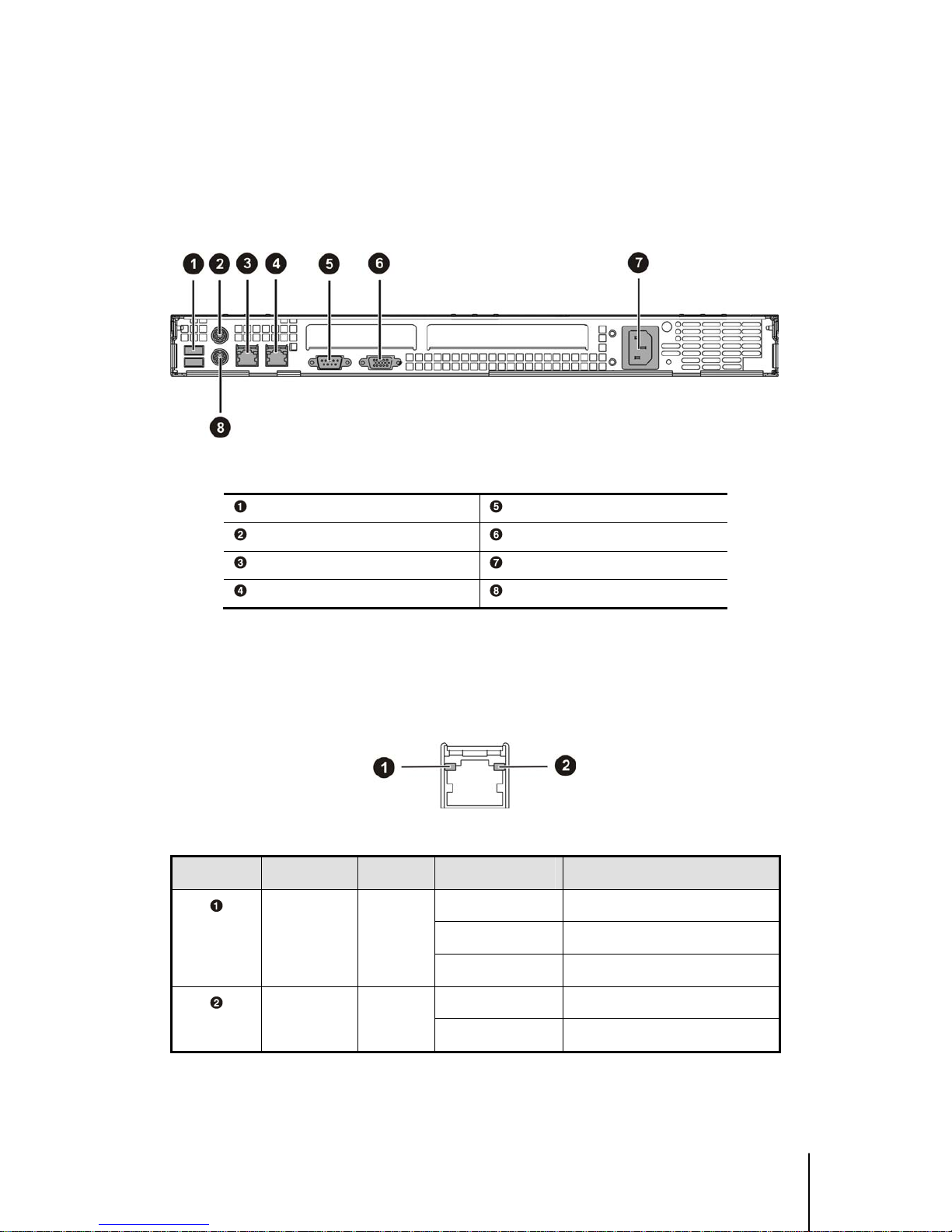
1.2.4 Back View
The server back view includes the connectors of the system devices and a slot for an expansion card.
Figure 1-5 Back View
Dual USB Port Serial Port
PS/2 Mouse Port D-sub VGA Port
NIC1 Connector (RJ45) AC Power Connector
NIC2 Connector (RJ45) PS/2 Keyboard Port
LED Information
The server back panel contains two LEDs that allow monitoring of network activity and server
identification.
Figure 1-6 NIC LED
Location LED Color LED State Condition
Yellow on Link on at 1Gbps speed
Green on Link at 10/100 Mbps speed.
LED 1
(Link)
Yellow
Green
Off No Link
Green Blinking NIC is accessing network
LED 2
(Activity)
Green
Off No network traffic
Table 1-2 NIC LED Information

Hardware Operation
This chapter provides information
and procedures for installing or
removing the hardware options on
Server.
Chapter 2
Hardware Operation

1230B0001801 Hardware Operation
2-1
22 HHaarrddwwaarree OOppeerraattiioonn
This chapter describes the hardware setup procedures that you have to perform when installing system
components. It also gives detailed information on the internal components and how to install them.
22..11 BBeeffoorree YYoouu SSttaarrtt
Take note of the following operations before you start to install or remove any internal components.
2.1.1 Power Off
The server does not completely power off when the front panel power button is pressed. The button
toggles server power between On and Standby. In Standby, the server removes power from most
electronics and drives, while portions of the power supply and some internal circuitry remain active.
To completely remove all power from the system, disconnect the power cord from the server.
Warning: To reduce the risk of injury from electric shock, remove the power cord to
completely disconnect power from the system.
Caution: Moving the Power On/Off switch to the Off position does not completely
remove system power. Some portions of the power supply and some internal circuitry
remain active. Disconnect all power cords from the server to remove all power from the
system.
To power off the server:
Press the power button
to toggle the
server to standby. Then the power LED
changes from green to off.
Figure 2-1 Pressing the power button

1230B0001801 Hardware Operation
2-2
Disconnect the power cord first from the
AC outlet and then from the server.
Figure 2-2 Disconnecting the power cord
22..22 CChhaassssiiss CCoovveerr
This server chassis is a 1U form factor designed for easy assembly and disassembly, making the
installation of internal components very convenient.
Important: Before you install or remove the chassis cover, make sure the power is off.
To power off the server, see “2.1.1 Power Off”.
To Install the Cover
To install the front top cover:
Slide the front top cover toward the
front until the right position and close the
front top cover.
Figure 2-3 Sliding the front top cover to the front
Secure the front top cover by
tightening the eight screws.
Figure 2-4 Securing the front top cover

1230B0001801 Hardware Operation
2-3
To install the rear top cover:
Put the rear top cover into the slot, and
slide the rear top cover toward the front
until the right position and close the rear
top cover.
Figure 2-5 Sliding the rear top cover to the front
Tighten the rear top cover with the
screw on the top.
Figure 2-6 Tightening screws on the top
1230B0001801 Hardware Operation
2-4
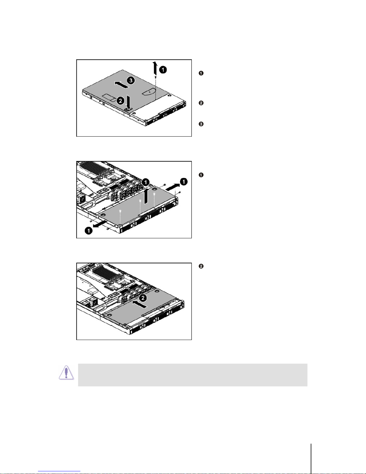
To Remove the Cover
To remove the rear top cover:
Loosen the screw on the top of the rear
top cover.
Press the button as the arrow shows.
Slide the rear top cover horizontally to
the back panel.
Figure 2-7 Removing the rear top cover
To remove the front top cover:
Loosen the screws on the top and side
of the front top cover.
Figure 2-8 Loosing the screws
Slide the front top cover horizontally
to the back and lift it.
Figure 2-9 Sliding the front top cover
out of the chassis
Caution: This unit must be operated with the chassis top cover installed to ensure
proper cooling.

1230B0001801 Hardware Operation
2-5
22..33 MMootthheerrbbooaarrdd
This section tells how to install the motherboard onto the chassis, for the main components operation
on the motherboard, please refer to the board manual.
The location of the motherboard on the server is shown as below:
Figure 2-10 Motherboard Location
Important:
• When installing the motherboard, make sure that you place it into the chassis
correctly. The edge with the external ports goes to the back panel of the chassis.
• Before you install or remove the motherboard, make sure the power is off. To power
off the server, see “2.1.1 Power Off”.

1230B0001801 Hardware Operation
2-6
To install the motherboard:
1. Put the motherboard on the chassis in the correct way.
2. Place 10 screws in the holes indicated by circles to secure the motherboard to the chassis.
Figure 2-11 Installing the motherboard
Caution: Do not over-tighten the screws. Doing so may damage the motherboard.
Reverse steps 1 through 2 to remove the motherboard.
1230B0001801 Hardware Operation
2-7
22..44 PPoowweerr SSuuppppllyy
The location of power supply on the server chassis is shown as below:
Figure 2-12 Power Supply Location
Important: Before you install or remove the power supply, make sure the power is off.
To power off the server, see “2.1.1 Power Off”.
To install the power supply:
Insert the power supply with an angle of
inclination to make it locked with the back
clips, and then press it down right into the
place.
Figure 2-13 Putting the power supply right into the place
Secure the power supply by tightening
the screws.
Figure 2-14 Securing the power supply
Reverse steps 1 through 2 to remove the power supply.

1230B0001801 Hardware Operation
2-8
22..55 SSyysstteemm FFaannss
Subdividing the motherboard area and the disk drives area is a metal bracket that holds the system
fans. The server supports four system fan modules and one single PCI-X fan. The fans are located on
the fan bracket. These fans maintain the ideal temperature for the motherboard and disk drives.
The location of the system fan on the server chassis is shown as below.
Figure 2-15 System Fans Location
Important: Before you install or remove the system fan, make sure the power is off.
To power off the server, see “2.1.1 Power Off”.
To install the system fan:
Push the system fan to the bracket to
make the two guide pins on the bracket
through the holes on the system fan.
Figure 2-16 Putting the system fans into the chassis

1230B0001801 Hardware Operation
2-9
Press the system fan down to make the
guide pin through the hole on the fan clip.
Figure 2-17 Fixing the system fan
Reverse steps 1 through 2 to remove the system fan.

1230B0001801 Hardware Operation
2-10
22..66 BBaacckkppllaannee ffoorr SSCCSSII HHDDDD
The backplane supports four SCSI HDDs in the system.
The design incorporates a Hot-Swap feature to allow easy installation of HDDs.
The backplane connector connects to the motherboard to indicate the access and failure for HDDs.
Figure 2-18 Backplane for SCSI
Backplane Power Connector Fan Power Connector
CD-ROM Power Connector PCI-X Fan Connector
I2C Signal Connector System Fan Connectors
SCSI Backplane Connector SCSI HDD Connectors
Fan Tach Connector
Important: Before you install or remove the backplane, make sure the power is off.
To power off the server, see “2.1.1 Power Off”.
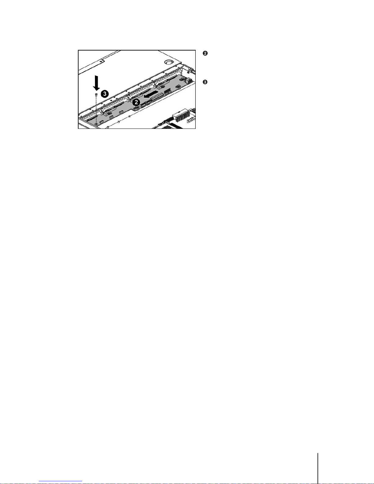
To install the backplane:
Aim the holes on the backplane at the
respective buttons on the chassis, and then
press it down.
Figure 2-19 Pressing down the backplane
1230B0001801 Hardware Operation
2-11
Push the backplane to the direction as
the arrow shows to lock it.
Fix it with one screw.
Figure 2-20 Fixing the backplane
Reverse steps 1 through 3 to remove the backplane.

1230B0001801 Hardware Operation
2-12
22..77 HHDDDDss
This server system comes up with four externally accessible HDD assemblies. The location of HDD
on the server chassis is shown as below.
Figure 2-21 HDD Assembly Location
Important:
• Take note of the drive tray orientation before you slide it out.
• The tray will not fit back into the bay if you insert it the wrong way.
• Before you install or remove the HDD, make sure the power is off. To power off the
server, see “2.1.1 Power Off”.
To install the HDD:
Locate the HDD on the tray and secure
it with the four mounting screws.
Figure 2-22 Locating the HDD to the HDD tray

1230B0001801 Hardware Operation
2-13
Carefully insert the HDD assembly
into the bay with the lever lifted until it
completely enters the bay.
Figure 2-23 Inserting the HDD assembly into the bay
Push the lever back in place.
Turn the lock on the lever clockwise to
secure the HDD.
Figure 2-24 Pushing the lever back in place
Important: Make sure that the HDD is connected to the HDD connector on the
backplane.
To remove the HDD:
. Turn the lock counterclockwise to
release the lever from the HDD.
Slide the HDD released button to the
direction of the arrow, and the lever will
be lifted automatically.
Figure 2-25 Releasing the lever from the HDD
1230B0001801 Hardware Operation
2-14
Slide the HDD assembly out of the
HDD bay.
Figure 2-26 Sliding the HDD assembly out of the HDD bay
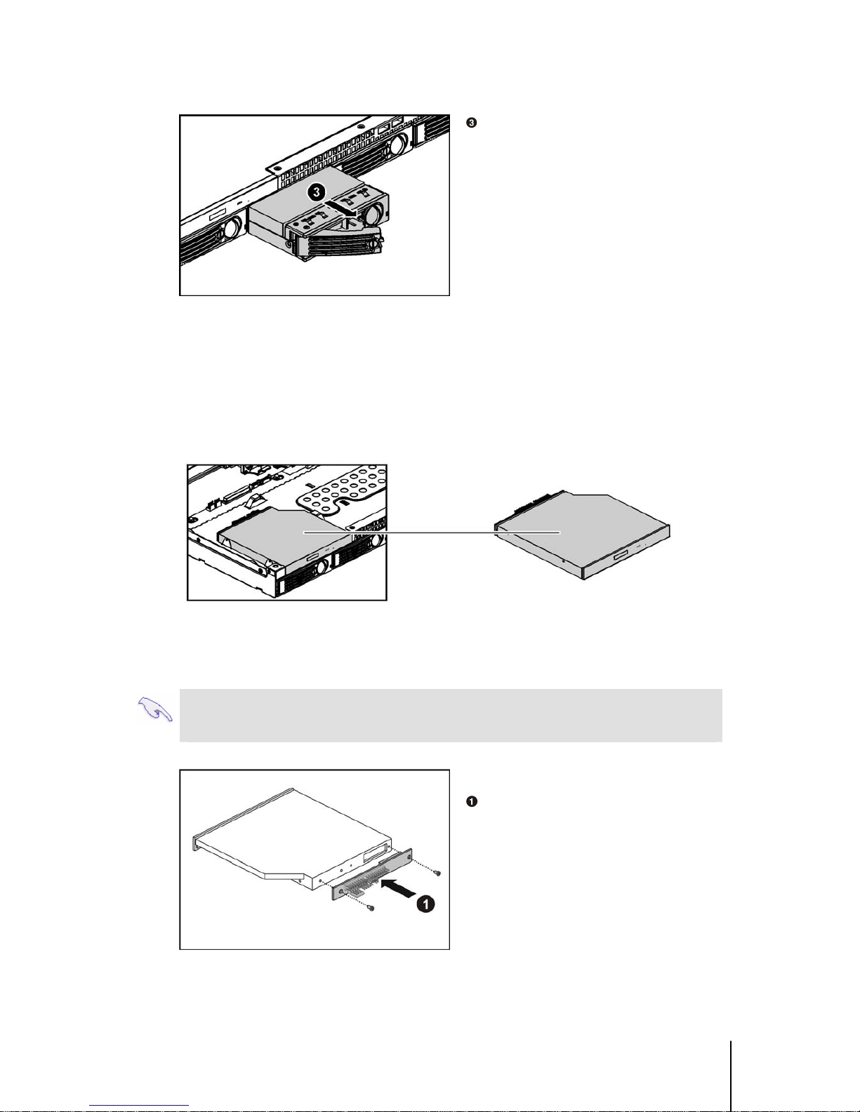
22..88 CCDD--RROOMM
The location of CD-ROM on the server chassis is shown as below.
Figure 2-27 CD-ROM Location
Important: Before you install or remove the CD-ROM, make sure the power is off. To
power off the server, see “2.1.1 Power Off”.
To install the CD-ROM:
Fix the CD-ROM daughter card to the
CD-ROM with two screws.
Figure 2-28 Fixing the CD-ROM daughter card to the CD-ROM

1230B0001801 Hardware Operation
2-15
Locate the CD-ROM righ t into the
place and lock it with the side clips.
Figure 2-29 Locating the CD-ROM into the place
Fix the CD-ROM with two screws.
Figure 2-30 Fixing the CD-ROM with screws
Reverse steps 1 through 3 to remove the CD-ROM.

1230B0001801 Hardware Operation
2-16
22..99 FFrroonntt PPaanneell
The location of front panel on the server chassis is shown as below.
Figure 2-31 Front panel Location
Important: Before you install or remove the front panel, make sure the power is off.
To power off the server, see “2.1.1 Power Off”.
To insert the front panel
Insert the front panel into the slot with
an angel of inclination and press it down
right into the place.
Figure 2-32 Inserting the front panel to the slot
Fix the front panel with three screws.
Figure 2-33 Fixing the front panel
Reverse steps 1 through 2 to remove the front panel.

1230B0001801 Hardware Operation
2-17
22..1100 RRiisseerr CCaarrdd AAsssseemmbbllyy
The location of riser card assembly on the server chassis is shown as below.
Figure 2-34 Riser Card Assembly Location
The motherboard has a 64bit/133MHz PCI-X expansion slot. The slot requires a PCI-X riser card
(P64-1U) to accommodate a PCI-X expansion card. The riser card comes with the system package.
The riser card golden fingers connect to the PCI-X slot on the motherboard. The card has a PCI-X
card connector for connecting a PCI-X expansion card.
Golden Fingers PCI-X Card Connector
Figure 2-35 Riser Card
Important: Before you install or remove the riser card, make sure the power is off. To
power off the server, see “2.1.1 Power Off”.
To install the riser card assembly:
Remove the slot cover.
Carefully insert the golden fingers of
the riser card to the connector on the riser
card retainer, and secure it to the riser card
board assembly with screws.
Figure 2-36 Securing the PCI-X riser card with screws

1230B0001801 Hardware Operation
2-18
Insert an expansion card into the
expansion slot by aligning the expansion
card with the board guide and sliding the
expansion card into the slot until the
board seats firmly.
Tighten the screw.
Figure 2-37 Inserting the expansion card to the slot
Press down the riser card assembly
firmly until it is seated in the expansion
slot on the server board.
Figure 2-38 Pressing down the riser card assembly
To remove the riser card assembly:
Lift the riser card assembly out of the
chassis.
Figure 2-39 Lifting the riser card assembly out of the chassis

This chapter provides the details of
all the necessary cables connection
and server installation.
Chapter 3
Cables and Server
Installation
Cables and Server Installation

1230B0001801 Cables and Server Installation
3-1
33 CCaabblleess aanndd SSeerrvveerr IInnssttaallllaattiioonn
This chapter provides the details of all the necessary cables connection and server installation for 1U
Server Chassis.
33..11 CCoonnnneeccttiinngg CCaabblleess
This section contains figures showing cable locations and descriptions of the connection procedures.
3.1.1 Front Panel Cables
Front Panel Cable
Connect one end of the front panel
cable to the connector on the
motherboard.
Figure 3-1 Connecting the front panel cable to the motherboard
Connect the other end of the front
panel cable to the connector on the front
panel.
Figure 3-2 Connecting the front panel cable to the front panel
1230B0001801 Cables and Server Installation
3-2
Front Panel USB Cable
Connect one end of the front panel
USB cable to USB header on the
motherboard.
Figure 3-3 Connecting the front panel USB cable to the motherboard
Connect the other end of the front
panel USB cable to the USB connector on
the front panel.
Figure 3-4 Connecting the front panel USB cable to the front panel
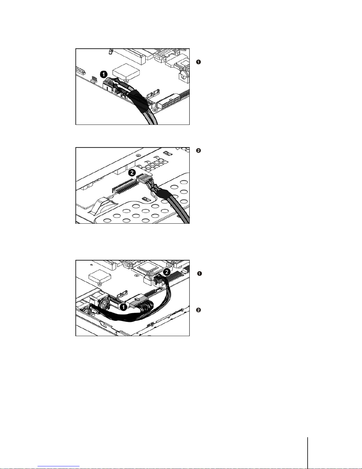
3.1.2 Power Cables
Main Power Cable
Connect the 24-pin main power cable
to the main power connector on the
motherboard.
Processor Power Cable
Connect the 8-pin processor power
cable to the processor power connector on
the motherboard.
Figure 3-5 Connecting the main power cable and processor power cable

1230B0001801 Cables and Server Installation
3-3
3.1.3 CD-ROM Cables
CD-ROM Cable
Connect one end of the CD-ROM
cable to the IDE connector on the
motherboard.
Figure 3-6 Connecting the CD-ROM cable to the motherboard
Connect the other end of the
CD-ROM cable to the connector on
CD-ROM daughter card.
Figure 3-7 Connecting the CD-ROM cable to the CD-ROM
CD-ROM Power Cable
Connect one end of the 4-pin
CD-ROM power cable to the CD-ROM
power connector on the backplane.
Connect the other end of the 4-pin
CD-ROM power cable to the power
connector on the CD-ROM daughter card.
Figure 3-8 Connecting the CD-ROM power cable

1230B0001801 Cables and Server Installation
3-4
3.1.4 SCSI HDD Cable
Connect one end of the SCSI HDD
cable to the connector on the SCSI
daughter card.
Figure 3-9 Connecting the SCSI HDD cable to the SCSI daughter card
Connect the other end of the SCSI
HDD cable to the connector on the SCSI
backplane.
Figure 3-10 Connecting the SCSI HDD cable to the backplane
3.1.5 Backplane Power Cable
Connect the 6-pin backplane power
Cable to the backplane power connector.
Figure 3-11 Connecting the backplane power cable
1230B0001801 Cables and Server Installation
3-5
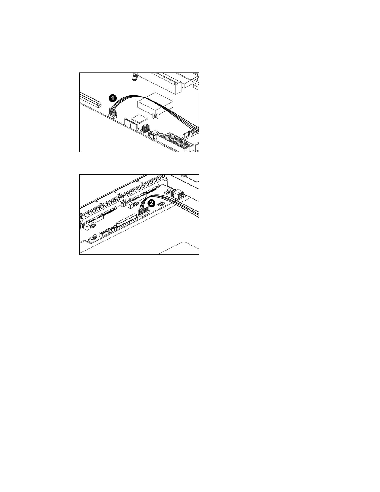
3.1.6 I2C Signal Cable
Connect one end of the I2C signal cable to
the I
2
C (SMBus) signal connector on the
motherboard.
Figure 3-12 Connecting the I
2
C signal cable to the motherboard
Connect the other end of the I2C signal
cable to the I
2
C signal connector on the
backplane.
Figure 3-13 Connecting the I
2
C signal cable to the backplane
1230B0001801 Cables and Server Installation
3-6
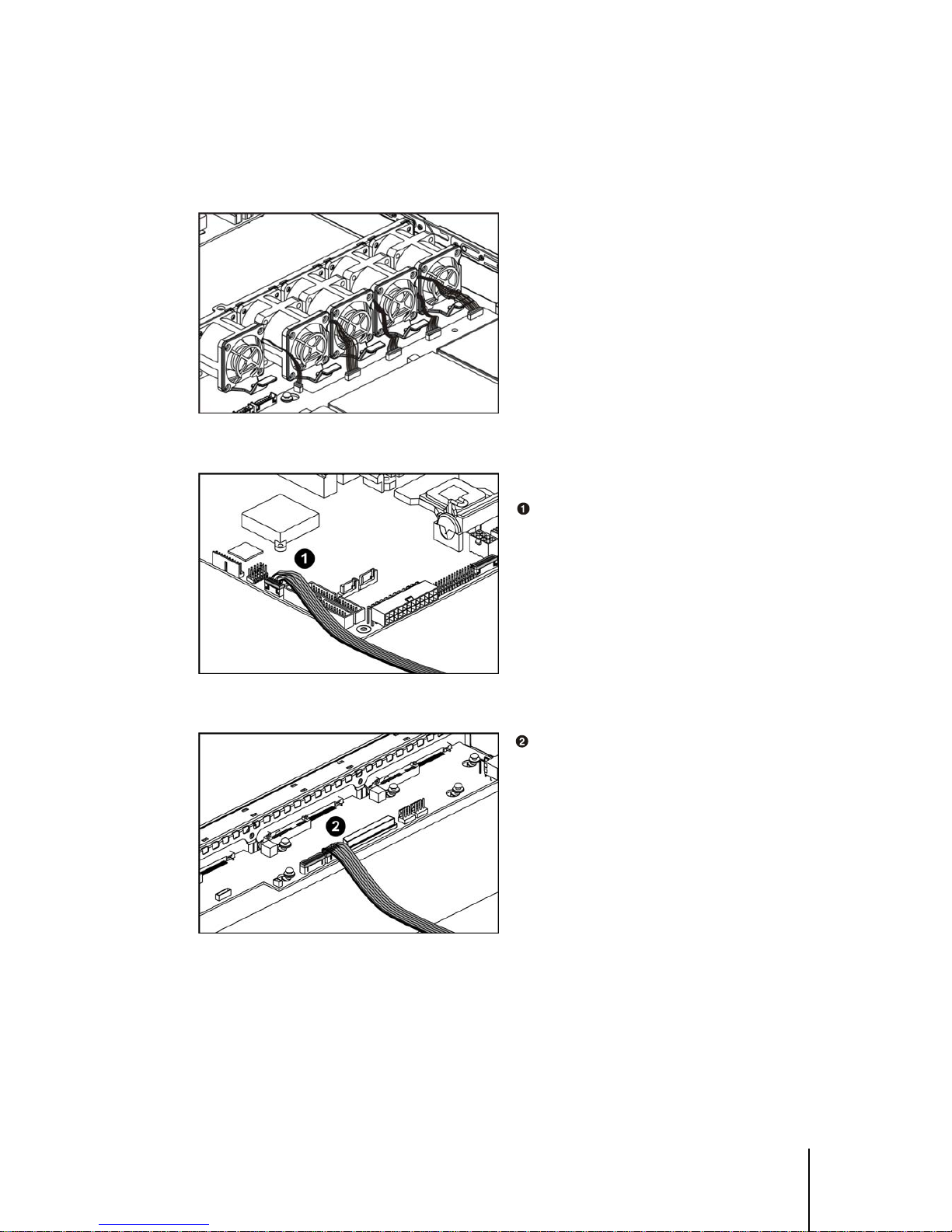
3.1.7 System Fan Cables
System Fan Cables
Connect the fan cables to their respective
connectors on the backplane.
Figure 3-14 Connecting the system fan cables
System Fan Tach Cable
Connect one end of the fan tach cable
to the fan tach connector on the
motherboard.
Figure 3-15 Connecting the system fan tach cable to the motherboard
Connect the other end of the fan tach
cable to the fan tach connector on the
backplane.
Figure 3-16 Connecting the system fan tach cable to the backplane
1230B0001801 Cables and Server Installation
3-7
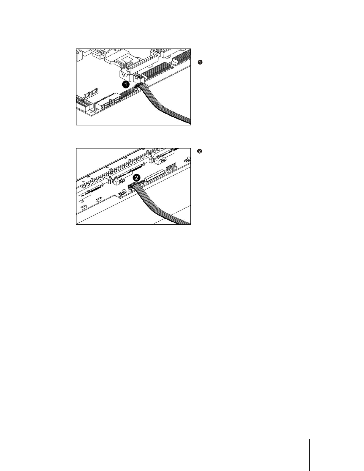
System Fan Power Cable
Connect one end of the fan power cable
to the fan power connector on the
motherboard.
Figure 3-17 Connecting the system fan power cable to the motherboard
Connect the other end of the fan power
cable to the fan power connector on the
backplane.
Figure 3-18 Connecting the system fan power cable to the backplane

1230B0001801 Cables and Server Installation
3-8
33..22 CCaabbllee VVeenntt BBaaffffllee
The cable vent baffle is a critical part to the server. Without the part, the sever will reduce thermal
performance and make inlet temperature of the power supply over spec.
Position the cable vent baffle onto the
system fan bracket with the notch upward
to insert the bracket in the notch of the
sponge.
Figure 3-19 Putting the cable vent baffle onto the system fan bracket
Important: The cable vent baffle shall be installed after all cables assembly is ready.

1230B0001801 Cables and Server Installation
3-9
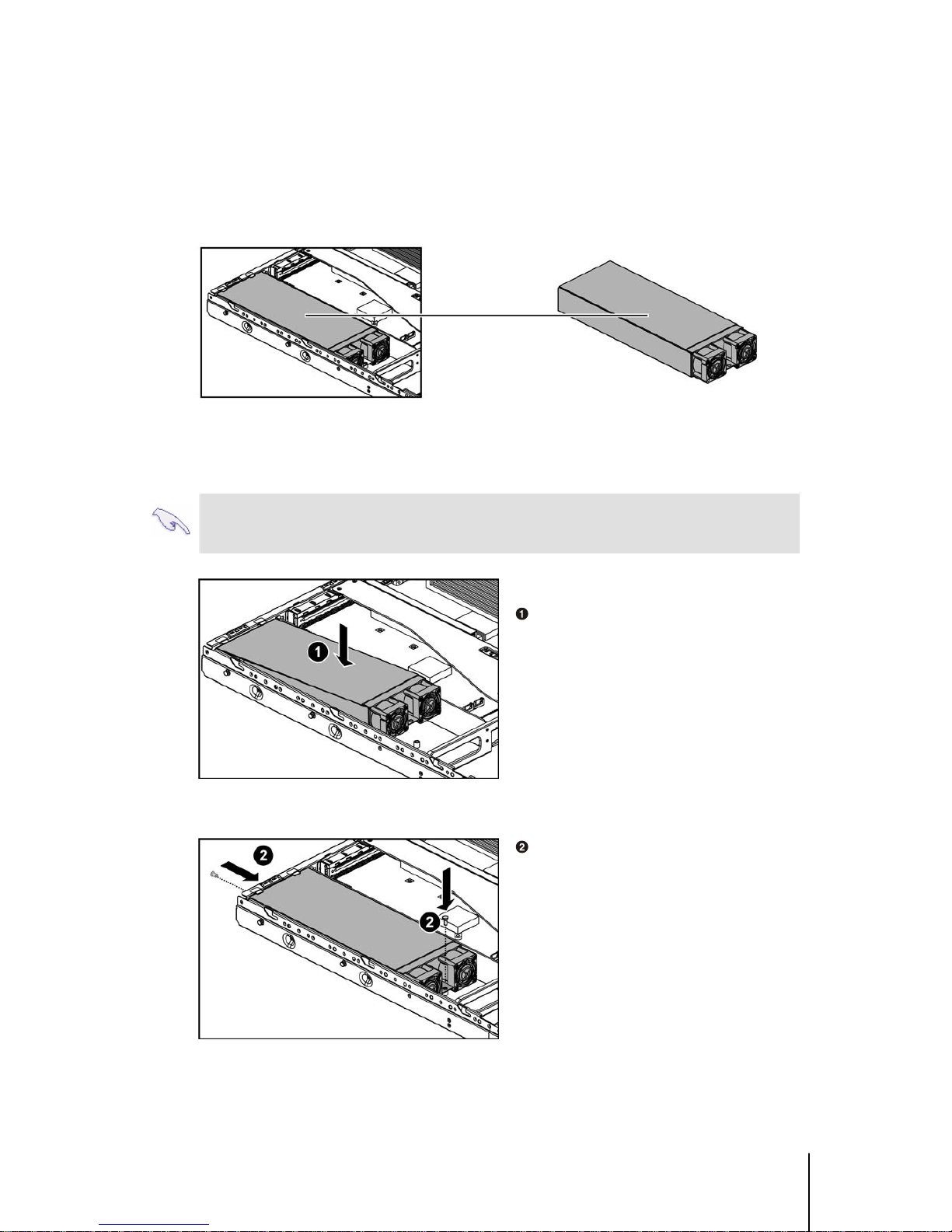
33..33 PPoowweerr SSuuppppllyy
The system comes with a 500W single power supply with universal AC input that includes PFC and
SSI-compliant output cables and connectors.
Figure 3-20 Power Supply Assembly
P1 Main Power Connector P3 I
2
C Power Connector
P2 Processor Power Connector P4 Backplane Power Connector
1230B0001801 Cables and Server Installation
3-10
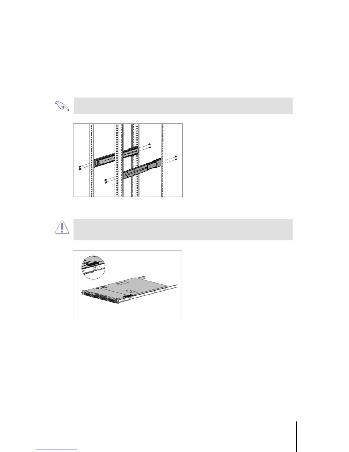
33..44 SSeerrvveerr IInnssttaallllaattiioonn
To install the rack-mounted server into the rack, complete the procedures described in the following
subsections.
Important: Ensure that the inner side of the rack rail faces the side of the rack.
Carefully align the two front tabs on the
front of the fixed rack rail with the holes
identified at the front of the rack.
Figure 3-21 Tightening the screws on the rack rail
Caution: To avoid destabilizing the rack, install multiple servers starting from the
bottom of the rack.
Attach the two rails on both sides and lock
it by sliding to the back with the screw
fixed in the key hole.
Figure 3-22 Attaching the two rails

1230B0001801 Cables and Server Installation
3-11
Align the rear end of the server rails on
the sides of the server with the front end
of the rack rails.
Insert the server fully into the rack,
ensuring that the fixed server rails slide
inside the fixed rack rails.
Figure 3-23 Inserting the server into the rack
Caution: Keep the server parallel to the floor when sliding the fixed server rails into
the slide rails. Tilting the server can damage the rails.

1230B0001801 Cables and Server Installation
3-12
33..55 PPoowweerr OOnn
Before you turn on the server, make sure that you have completed the basic system connections.
Follow these steps when starting the server.
Step 1: Monitor Connection
Connect a monitor by plugging a video cable to the video port (blue port) at the back of the server.
Step 2: PS/2 Keyboard Connection
Plug the keyboard cable into the keyboard port on the back of the server.
Step 3: PS/2 Mouse Connection
For a PS/2 mouse, plug the mouse cable into the mouse port on the back of the server.
Step 4: Power Connection
Connect a power cord to the AC power connector at the back of the server, and then plug the power
cord to a grounded wall socket.
Note: There is only one way to plug in all the connectors.
Figure 3-24 Connect Cables for Power On
PS/2 Mouse Port AC Power Connector
D-sub VGA Port PS/2 Keyboard Port

1230B0001801 Cables and Server Installation
3-13
Step 5: Power on
Pressing the power button on the front panel to toggle the server to power. The power LED
turns to be green.
Figure 3-25 Pressing the power button
 Loading...