

Pengo Computer Accessories UBR7200 User Manual

Multipoint Wireless Support for the Cisco
uBR7200 Series Universal Broadband Router
The Cisco broadband fixed wireless multipoint system is an integrated solution consisting of a headend,
or base station, and multiple subscriber units. This document describes the fixed wireless multipoint
feature (headend) support for the Cisco uBR7200 series universal broadband router. This document
includes the following sections:
• Feature Overview, page 1
• Supported Platforms, page 5
• Supported Standards, MIBs, and RFCs, page 5
• Prerequisites, page 5
• Configuration Tasks, page 5
• Monitoring and Maintaining Multipoint Wireless Configurations, page 12
• Configuration Examples, page 15
• Command Reference, page 17
• Debug Commands, page 162
• Glossary, page 180
Feature Overview
This documentdescribesthemultipointheadend system. For a description of the subscriber unit system,
refer to the Multipoint Wireless Support for the Cisco 2600 and 3600 Series Routers document.
Cisco IOS Release 12.1(5)XM
1
Multipoint Wireless Support for the Cisco uBR7200 Series Universal Broadband Router
Feature Overview
Multipoint Headend System
The Cisco broadband fixedwireless multipoint headend system is designed to use antennas that transmit
the RF signal in a portion of a complete circle, or directionally, in what is called a sector. Each headend
site can be designed and configured to broadcast in a single sector, or in multiple sectors, depending on
the requirements of the network.
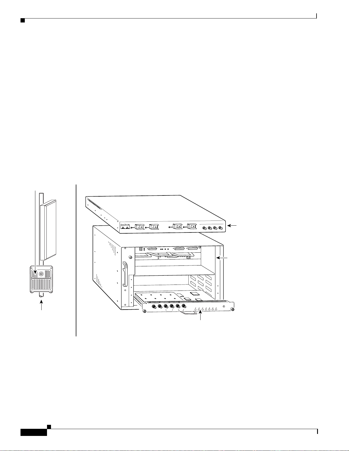
For each sector, the components of a multipoint headend system (see Figure 1) consist of the necessary
cables and:
• One Cisco uBR7200 series universal broadband router
• One wireless modem card installed in the router
• One power feed panel
• One or two antennas (second antenna for diversity reception is optional)
• One or two wireless transverters containing the RF amplifier (one for each antenna)
• One or two duplexers (one for each wireless transverter)
Figure 1 Components of the Multipoint Headend System (transverter hail shield not shown)
Duplexer
Wireless
point-to-multipoint
transverter
4
1
PWR
ON
ON
ON
PWR
ON
2
1
OFF
OFF
2
3
OFF
3
ON
PWR
ON
4
PWR
ON
OFF
ON
CISCO uBR – WMF4A
POWER FEED PANEL
MCW 4
MCW 3
MCW 2
MCW 1
Point-to-multipoint
power feed panel
Cisco uBR7200
series router
uBR-MCW-MDA
ENABLED
MAJOR ALARM
MINOR ALARM
OUT OF SERVICE
CARRIER
SEND DATA
RECEIVE DATA
PFP
MONITOR
PFP
MONITOR
10MHz
10MHz
IN
OUT
DIVERSITY
MAIN
Point-to-multipoint
head-end
wireless modem card
35167
Cisco IOS Release 12.1(5)XM
2

Multipoint Wireless Support for the Cisco uBR7200 Series Universal Broadband Router
Multipoint Headend Components
Router
The Cisco uBR7200 series are designed for two-way transmission of digital data using either coaxial
cable or broadband fixed wireless signals. These routers support IP routing with a wide variety of
protocols and any combination of Ethernet, Fast Ethernet, High-Speed Serial Interface (HSSI), serial,
and Asynchronous Transfer Mode (ATM) media. Network interfaces reside on port adapters that
provide the connection between the router and external networks. Cable or wireless interfaces reside on
modem cards and provide the connection to cable or wireless networks.
Other features include:
• Online insertion and removal (OIR)—Add, replace, or remove a port adapter and modem cards
without interrupting the system or entering any console commands
• Downloadable software—Load new images into Flash memory remotely, without having to
physically access the router
For further information regarding the Cisco uBR7200 series, including detailed installation and
configurationinstructions, refer to the Cisco uBR7200 Series Universal Broadband Router Installation
and Configuration Guide.
Feature Overview
Wireless Modem Card
The wireless modem card installs in a modem card slot of a Cisco uBR7200 series. It is configured
through the router’s system console or via the CiscoView network management system. The wireless
modem card provides the control and data interface to the system’s digital motherboard and the radio
frequency (RF) subsystem in the wireless transverter. It also provides the up/down conversion from
baseband to intermediate frequency (IF).
The wireless modem card consists of the following components:
• Digital motherboard
• IF analog board
• 10-MHz input connection for external reference clock signal (external reference clock is optional)
• 10-MHz output connection for forwarding optional external reference clock signal to another
wireless modem card
• Monitor connections for monitoring the power feed panel connections (main and diversity)
• Power feed panel connections (main and diversity)
• Light-emitting diodes (LEDs) that provide a visual indication of the state of the modem card
For further information regarding the wireless modem card, including detailed installation and
configuration information, refer to the Cisco uBR7200 Series Router Multipoint Wireless Modem Card
and Subsystem Installation document.
Power Feed Panel
The power feed panel serves as an interconnection device between the wireless modem card, the
wireless transverter, and a –48 VDC power supply. The main purpose of this unit is to provide
DC power to the system, provide control signals to the wireless transverter, and transmit and receive IF
signals to and from the transverters. In addition, the unit contains circuit breakers for the DC power.
Cisco IOS Release 12.1(5)XM
3

Feature Overview
The power feed panel consists of the following components:
• Coaxial cable connection ports to the wireless modem card on the front panel
• Power ON/OFF switches on the front panel, with LED power indicators
• Coaxial cable connection ports to the wireless transverter on the rear panel, with LED power
• DC power supply terminal blocks on the rear panel
At least one power feed panel is required for each installation. Each power feed panel supports a
maximum of four wireless transverters.
For further information regarding the power feed panel, including detailed installation information,
refer to the Cisco uBR7200 Series Router Multipoint Wireless Modem Card and Subsystem Installation
document.
Wireless Transverter
The ruggedized wireless transverter is the outdoor data interface to the indoor subsystems. It provides
up/down conversion from IF to RF frequencies.
The wireless transverter consists of the following components:
• RF head
• Connector port for IF input, power, and control signal
• Duplexer assembly with antenna connection
For further information regarding the wireless transverter, including detailed installation information,
refer to the Cisco uBR7200 Series Router Multipoint Wireless Modem Card and Subsystem Installation
document.
Multipoint Wireless Support for the Cisco uBR7200 Series Universal Broadband Router
indicators
Benefits
The broadband fixed wireless multipoint system provides:
• Fast, easy deployment
• Flexibility—Various interfaces to the host routers and numerous network deployment plans
• End-to-end Cisco IOS network, enabling multiservice security, multimedia, and management
support
• Scalable network growth through the addition of more cells or sectors
• Full-duplex data rates of up to 22 Mbps
• Non-line-of-sight (Non-LOS) Vector Orthogonal Frequency Division Multiplexing (VOFDM)
technology, enabling greater service coverage
Related Features and Technologies
The point-to-point wireless router system.
Cisco IOS Release 12.1(5)XM
4

Multipoint Wireless Support for the Cisco uBR7200 Series Universal Broadband Router
Related Documents
Headend documents:
• Cisco uBR7200 Series Multipoint Wireless Modem Card & Subsystem Installation
• Cisco Multipoint Headend Wireless Transverter Duplexer Replacement Instructions
• Cisco Multipoint Headend Power Feed Panel Replacement Instructions
• Cisco Multipoint Headend Wireless Transverter Replacement Instructions
• Cisco Wireless Transverter Hail Shield Installation Instructions
Subscriber-unit documents:
• Multipoint Wireless Support for the Cisco 2600 and 3600 Series Routers
• Cisco 2600 Series Hardware Installation Guide
• Software Configuration Guide (for Cisco 3600 series and Cisco 2600 series routers)
• Cisco Network Modules Hardware Installation Guide (for Cisco 3600 series and Cisco 2600 series
routers)
Supported Platforms
Supported Platforms
uBR7200 series
Supported Standards, MIBs, and RFCs
Standards
DOCSIS 1.0 and 1.0+. The DOCSIS 1.0+ implementation is DOCSIS 1.0 with quality-of-service (QoS)
support.
MIBs
This feature is supported by Cisco uBR7200 series MIBs and DOCSIS MIBs enhancing the
manageability of customer infrastructures.
To obtain lists of MIBs supported by platform and Cisco IOS release and to download MIB modules, go to
the Cisco MIB web site on Cisco Connection Online (CCO) at
http://www.cisco.com/public/sw-center/netmgmt/cmtk/mibs.shtml.
RFCs
No new or modified RFCs are supported by this feature.
Prerequisites
Multipoint wireless support
Cisco IOS Release 12.1(5)XM
5

Multipoint Wireless Support for the Cisco uBR7200 Series Universal Broadband Router
Configuration Tasks
Configuration Tasks
This section discusses the following configuration tasks for the multipoint fixed wireless feature:
• Multipoint CLI Commands Classification
• Overriding the Default Microcode Path
• Configuring IF Loopback (Optional)
• Configuring RF Loopback (Optional)
• Setting the Power Levels and Frequencies
• Configuring the Automatic Level Control (ALC)
• Configuring the Modulation Profile for a Wireless Link
Multipoint CLI Commands Classification
The multipoint headend system CLI commands are classified as follows. Click on the link to go to the
list of commands under each class.
• Startup Commands
• Installation and Configuration Commands
• Verification Commands
• Operating Commands
• Monitoring Commands
• Troubleshooting Commands
Note This classification is made to help the user in chunking the commands. Some of the
commands can be listed under any of these groups.
Cisco IOS Release 12.1(5)XM
6

Multipoint Wireless Support for the Cisco uBR7200 Series Universal Broadband Router
Overriding the Default Microcode Path
The wireless line card requires external microcode images in order to operate. The Cisco IOS software has
a default file path where it looks to find the microcode and the microcode version. For routers that are
configured with line cards at the factory, the path and version of the microcode image in flash memory
matches the default setting and allows the line card to come up without any additional configuration.
However, you may want to override the default microcode path, for example, to upgrade your software to
the latest release. Use the following steps to change the path for the microcode.
Command Purpose
Step 1
Step 2
Step 3
Step 4
Step 5
Step 6
Step 7
Step 8
Router# dir flash
Router# show microcode
Router# config t
Router(config)# microcode cwrhe
Router(config)# end
Router# show microcode
Router# microcode reload cwrhe
Router# copy running-config startup-config
bundle-path
Configuration Tasks
Displays the content of the Flash memory.
Displays the default path for the microcode.
Enters the global configuration mode.
Specifies the a new path for the headend
microcode bundle.
Exits the global configurationmode and enters the
EXEC mode.
Displays the specified path for the microcode.
Loads the microcode onto the line card.
Saves the path for the microcode so that the
microcode is loaded from the new path the next
time the router is rebooted.
Configuring IF Loopback (Optional)
An IF loopback confirms that the hardware is seated properly in the chassis and that the analog and signal
processing portions of the wireless modem card are functioning as expected. Loopback does not test
forward error corrections (FEC) and MAC-layer interface of the line card; other tests must be done for these
portions of the line card. Each receive path must be tested individually when there are two antennas
employed.
Use the following commands to execute an IF loopback. Specifying these commands shuts down the
radio link and initiates the IF loopback.
Command Purpose
Step 1
Step 2
Step 3
Step 4
Step 5
Step 6
Step 7
Router(config-if)# shut
Router(config-if)# loopback local if main 2
Router(config-if)# no shut
Router(config-if)# shut
Router(config-if)# loopback local if main 3
Router(config-if)# no shut
Router(config-if)# shut
Stops the interface.
Configures the IF to loop the lower half of the
channel.
Brings up the loopback mode.
Stops the interface.
Configures the IF to loop the upper half of the
channel.
Brings up the loopback mode.
Stops the interface.
Cisco IOS Release 12.1(5)XM
7

Configuration Tasks
Command Purpose
Step 8
Step 9
Router(config-if)# no loopback
Router(config-if)# no shut
Command Purpose
Step 1
Step 2
Step 3
Step 4
Step 5
Step 6
Step 7
Step 8
Step 9
Router(config-if)# shut
Router(config-if)# loopback local if diversity 2
Router(config-if)# no shut
Router(config-if)# shut
Router(config-if)# loopback local if diversity 3
Router(config-if)# no shut
Router(config-if)# shut
Router(config-if)# no loopback
Router(config-if)# no shut
Multipoint Wireless Support for the Cisco uBR7200 Series Universal Broadband Router
Removes the loopback commands used up to this
point.
Establishes link.
If a second antenna is employed, its receive path must also be tested. Use the following commands to
configure the second antenna. Issue the show running-configuration command to see the IF
configuration.
Stops the interface.
Configures the IF to loop the lower half of the
channel for antenna 2.
Brings up the loopback mode.
Stops the interface.
Configures the IF to loop the upper half of the
channel for antenna 2.
Brings up the loopback mode.
Stops the interface.
Removes the loopback commands used up to this
point.
Establishes link.
Configuring RF Loopback (Optional)
An RF loopback confirms that the wiring to the transverter is correct, that communication has been
established from the line card to the transverter, and that the transverter is operating correctly. (It does not
test the duplexer, which is the final stage before the signal is sent to the antenna.) Also, loopback does not
test forward error corrections (FEC) and MAC-layer interface of the line card; other tests must be done for
these portions of the line card. Because there is only one transmit path, the path to each transverter must be
tested separately. Use the following commands to configure the RF loopback.
Command Purpose
Step 1
Step 2
Step 3
Step 4
Step 5
Step 6
Step 7
Router(config-if)# shut
Router(config-if)# loopback local rf main 2
Router(config-if)# no shut
Router(config-if)# shut
Router(config-if)# loopback local rf main 3
Router(config-if)# no shut
Router(config-if)# shut
Stops the interface.
Configures the RF to loop the lower half of the
channel.
Brings up the loopback mode.
Stops the interface.
Configures the RF to loop the upper half of the
channel.
Brings up the loopback mode.
Stops the interface.
Cisco IOS Release 12.1(5)XM
8

Multipoint Wireless Support for the Cisco uBR7200 Series Universal Broadband Router
Command Purpose
Step 8
Router(config-if)# loopback local rf diversity 2
Configures the RF to loop the lower half of the
channel for antenna 2. Note that this command is
issued only if a second antenna is used.
Step 9
Router(config-if)# loopback local rf diversity 3
Configures the RF to loop the upper half of the
channel for antenna 2. Note that this command is
issued only if a second antenna is used.
Step 10
Step 11
Step 12
Router(config-if)# no shut
Router(config-if)# shut
Router(config-if)# no loopback
Brings up in loopback mode.
Stops the interface.
Removes any loopback commands used up to this
point.
Step 13
Router(config-if)# no shut
Establishes link.
Issue the show running-configuration command to see the RF configuration.
Configuring the Modulation Profile for a Wireless Link
Configuration Tasks
Step 1
Step 2
Step 3
Step 4
Step 5
Step 6
Step 7
Step 8
The modulation profile describes the physical layer configuration of a wireless channel. The correct settings
to use are the result of extensive site planning and quality-of-service models. The specified settings are
stored in the router as profiles. These profile settings are entered in the router only once, but can be applied
to multiple line cards in the router.
Command Purpose
Router# show radio capability modulation-profile int
radio
slot/port
Router# configure terminal
Router(config)# radio modulation-profilep bandwidth
width
throughput
medium
Router(config)# end
x.y
mulipath-robust
high
burst-length
Displays the modulation profilessupported by the
radio card installed in a particular slot/port.
Enables the global interface configuration mode.
Creates a modulation profile.
Exits the interface configuration mode and enters
the EXEC mode.
Router# show radio modulation-profile
Displays the modulation-profile configuration
settings that the user specified.
Router# configure terminal
Router(config)# interface radio
Router(config-if)# radio upstream
modulation-profile
p
slot/port
usport
subchannel
Enables the global interface configuration mode.
Enters radio interface configuration mode.
sn
Applies the modulation profile to an upstream
port.
Cisco IOS Release 12.1(5)XM
9
Multipoint Wireless Support for the Cisco uBR7200 Series Universal Broadband Router
Configuration Tasks
Setting the Power Levels and Frequencies
The power levels must be set correctly to ensure correct operation and compliance with the governing
regulatory bodies (such as the FCC). After the power settings have been determined, use the following
commands to configure the router.Refer to the following subchannel map as a reference for the
subchannel assignments:
one "channel"
1
23
4567
35543
Downstream Channel
Step 1
Step 2
Step 3
Command Purpose
Router(config-if)# radio transmit-power
power-level
Sets the upstream transmit-power to power in
dBm.
Router(config-if)# radio downstream frequency
width
width
Router(config-if)# radio downstream subchannel
modulation-profile
p
freq
sc
Sets frequency and bandwidth for the downstream
channel.
Sets the subchannel and modulation-profile
assignment for the downstream channel.
Note This command specifies the center
frequencyand width of the basic hardware
channel. The downstream channel itself
can be full, one-half, or one-quarter of this
bandwidth. For example, the only basic
channel bandwidth that is supported by
the initial hardware release is 6.0 MHz.
10
Cisco IOS Release 12.1(5)XM

Multipoint Wireless Support for the Cisco uBR7200 Series Universal Broadband Router
Upstream Channel
Command Purpose
Step 1
Router(config)# radio upstream frequency
width
freq
width
Configuration Tasks
Sets the upstream frequency and bandwidth.
Note The width parameter specifies the
bandwith for the upstream channel group
(the basic hardware channel). The freq
parameter specifies the center frequency
for this group of upstream channels. For
example,the only basic channel width that
is supported by the initial hardware
release is 6.0 MHz.
Step 2
Step 3
Step 4
Step 5
Router(config-if)# radio upstream
sn modulation-profile
Router(config)# radio transmit-power
Router(config-if)# radio upstream
target-receive-power
Router(config-if)# radio upstream
p
power-level
usportnum
power-level
usportnum
usportnum
subchannel
shutdown
Configuring the Automatic Level Control (ALC)
The automatic level control (ALC) module governs the individual transmit power levels of all the
subscriber units. The purpose of ALC is to ensure that the target receive power at the headend is maintained
over time by taking power measurements of all the subscribers many times per second. Taking power
measurements in small intervals results in better resilience to the fading environment, but it consumes more
upstream bandwidth. ALC can be disabled, but this is not recommended because it results in poor upstream
link performance. The current system allows only one interval setting for an entire sector. The default
interval is 96 ms.
Sets the subchannel and modulation-profile
assignment for the upstream channel.
Note The bandwidth of the subchannel must
match the bandwidth of the
modulation-profile.
Sets the downstream transmit power to power in
dBm.
Sets the target receive power in dBm for the
upstream port. The usportnum field specifies the
upstream port number. The target receive power
must be set for each upstream port.
Shuts down the upstream channel.
Step 1
Step 2
Step 3
Command Purpose
Router# configure terminal
Router(config)# interface radio
slot/port
Enables the global interface configuration mode.
Specifies the line card to be configured. In this
example, the line card installed in a specific
slot/port number.
Router(config-if)# radio alc interval
interval
Configures the ALC interval for the sector at a
specified interval value.
Cisco IOS Release 12.1(5)XM
11

Multipoint Wireless Support for the Cisco uBR7200 Series Universal Broadband Router
Monitoring and Maintaining Multipoint Wireless Configurations
Command Purpose
Step 4
Router(config-if)# end
Exits the interface configuration mode and get to
the EXEC mode.
Step 5
Router# show interface radio
slot/port
alc
Displays the ALC setting that you specified.
Verifying the Wireless Modem Card Configuration
Step 1 Enter the show running-configuration command in privileged EXEC mode to display the
configuration currently in effect on the Cisco uBR7200 series.
Step 2 Enter the show startup-configuration command in privileged EXEC mode to display the system
startup configuration.
For a complete list of commands to verify the installation and configuration of your fixed wireless
multipoint system, see the “Verification Commands”section.
Monitoring and Maintaining Multipoint Wireless
Configurations
This section describes the clear and show commands that are used to monitor and maintain the
multipoint fixed wireless system. For a complete list of commands to monitor and maintain your fixed
wireless multipoint system, see “Monitoring Commands” under the command reference section. For the
syntax and description of a command, refer to the “Command Reference” section of this document.
Command Purpose
Router# clear radio flap-list
Router# clear radio link-metrics
Router# clear radio subscriber counters
Router# clear radio subscriber reset
Router# show controllers radio downstream
Router# show controllers radio if
Router# show controllers radio rf
Router# show controllers radio upstream
Router# show interfaces radio metrics
Router# show interface radio accounting
Clears the current radio flap-list entries for a
specific subscriber unit or for all subscriber units.
Clears the link metrics settings.
Clears the counters for a radio modem or all radio
modems in the Station Maintenance List.
Resets the radio modem or all radio modems on the
network.
Displays downstream port information for a
wireless modem card.
Displays the IF hardware information for the
specified radio interface.
Displays the RF hardware information for the
specified radio interface.
Displays upstream port information for a wireless
modem card.
Displays the parameters measured during the
operation of the radio link.
Displays radio accounting information for a
wireless modem card.
12
Cisco IOS Release 12.1(5)XM

Multipoint Wireless Support for the Cisco uBR7200 Series Universal Broadband Router
Monitoring and Maintaining Multipoint Wireless Configurations
Command Purpose
Router# show interface radio alc
Displays the automatic level control (ALC) and
power ranging configuration information for the
downstream.
Router# show interface radio downstream
Displays downstream port information for a
wireless modem card.
Router# show interface radio hist-data
Router# show interface radio hist-spec
Router# show interface radio led
Displays histogram data.
Displays histogram specifications.
Displaysthe status of light-emitting diodes(LEDs)
on the wireless modem card and the events related
to the major and minor LEDs.
Router# show interface radio ranging
Router# show interface radio rf-meas-interval
Displays ranging information.
Displays the intervals of the ambient noise and the
calibration noise measurements of the radio card
for the specified slot and downstream port
numbers.
Router# show interface radio sid
Displays information by service identifier (SID)
about each subscriber unit on the network.
Router# show interface radio snap-data
Displays the data captured for the snapshot
specification.
Router# show interface radio snap-spec
Router# show interface radio thresholds
Displays the configured snapshot information.
Displays the set of currently configuredthresholds
on the radio modem card.
Router# show interface radio tl-data
Displays the timelines data collected for the
identified specifications.
Router# show interface radio tl-spec
Displays the details of the currently configured
timeline specifications.
Router# show interface radio upstream
Displays upstream port information for a wireless
modem card.
Router# show interface radio zero-burst
Displays zero-burst information for the
downstream port of a wireless modem card.
Router# show radio device
Displays the access group information for the
subscriber unit or the host behind the subscriber
unit.
Router# show radio errors
Router# show radio flap-list
Displays error details for the radio interface.
Displays the radio flap-list of a wireless modem
card.
Router# show radio capability modulation-profile
Displays the modulation profiles supported by the
radio linecard.
Router# show radio modulation-profile
Displays modulation profile information for a
wireless modem card that the user specified.
Router# show radio privacy kek
Displays the key encryption life-time and
grace-time values that have been set.
Cisco IOS Release 12.1(5)XM
13

Multipoint Wireless Support for the Cisco uBR7200 Series Universal Broadband Router
Monitoring and Maintaining Multipoint Wireless Configurations
Command Purpose
Router# show radio privacy tek
Displays the traffic encryption life-time and
grace-time values that have been set.
Router# show radio qos profile
Displays quality-of-service (QoS) profile and the
configuration information for the profile.
Router# show radio subscriber
Displays information about a wireless modem card
that is on the network.
14
Cisco IOS Release 12.1(5)XM

Multipoint Wireless Support for the Cisco uBR7200 Series Universal Broadband Router
Configuration Examples
This section provides the following examples for configuring the multipoint headend wireless modem
car:
• RF-RF Link Configuration
• Downstream Channel Configuration
• Upstream Channel Configuration
• Modulation Profiles Configurations
RF-RF Link Configuration
The following is an example of RF-RF link configuration:
interface Radio3/0 multipoint
ip address 7.7.7.1 255.255.255.0
radio cable-loss auto
radio transmit-power 34
radio upstream frequency 2503000 width 6.0
radio upstream 0 subchannel 2 modulation-profile 8
no radio upstream 0 shutdown
radio upstream 1 shutdown
radio upstream 2 shutdown
radio upstream 3 shutdown
radio downstream frequency 2545000 width 6.0
radio downstream subchannel 2 modulation-profile 1
Configuration Examples
Downstream Channel Configuration
The following is an example of downstream channel configuration:
radio transmit-power 31
radio downstream frequency 2653000 width 6.0
radio downstream subchannel 4 modulation-profile 10
Upstream Channel Configuration
The following is an example of upstream channel configuration:
radio upstream frequency 2587000 width 6.0
radio upstream 0 subchannel 4 modulation-profile 14
radio upstream 0 target-receive-power -72
no radio upstream 0 shutdown
radio upstream 1 subchannel 5 modulation-profile 14
radio upstream 1 target-receive-power -72
no radio upstream 1 shutdown
radio upstream 2 subchannel 6 modulation-profile 14
radio upstream 2 target-receive-power -72
no radio upstream 2 shutdown
radio upstream 3 subchannel 7 modulation-profile 14
radio upstream 3 target-receive-power -72
no radio upstream 3 shutdown
Cisco IOS Release 12.1(5)XM
15

Multipoint Wireless Support for the Cisco uBR7200 Series Universal Broadband Router
Configuration Examples
Splitting an upstream channel
The following steps show how to split an upstream channel into two smaller upstream channels. In this
example, a 3-MHz upstream (upstream 0, subchannel 2) is split into two 1.5-MHz upstreams, using the
following commands. Refer to the following subchannel map as a reference for the subchannel
assignments:
one "channel"
1
23
4567
35543
Command Purpose
Router(config-if)# no radio upstream 0 subchannel
Router(config-if)# radio upstream 0 subchannel 4
modulation-profile 7
Router(config-if)# radio upstream 1 subchannel 5
modulation-profile 7
Router(config-if)# no radio upstream 0 shutdown
Router(config-if)# no radio upstream 1 shutdown
Removes the subchannel assignment from
upstream port 0.
Assigns upstream port 0 to subchannel 4 using
modulation profile 7, which must be a 1.5-MHz
modulation profile.
Assigns upstream 1 to subchannel 5, using
modulation profile 7.
Enables upstream 0.
Enables upstream 1.
Modulation Profiles Configurations
The following are examples of modulation profiles:
radio modulation-profile 1 bandwidth 3.0 throughput 6.6 multipath-robustness high
burst-length medium
radio modulation-profile 2 bandwidth 3.0 throughput 8.6 multipath-robustness high
burst-length medium
radio modulation-profile 3 bandwidth 3.0 throughput 4.4 multipath-robustness high
burst-length medium
Cisco IOS Release 12.1(5)XM
16

Multipoint Wireless Support for the Cisco uBR7200 Series Universal Broadband Router
Command Reference
This section documents the new commands associated with the fixed wireless multipoint feature. All
other commands used with this feature are documented in the Cisco IOS Release 12.1 command
reference publications. The commands are classified into the following groups:
• Startup Commands
• Installation and Configuration Commands
• Verification Commands
• Operating Commands
• Monitoring Commands
• Troubleshooting Commands
Note This classification is created to help the user in chunking the commands. Some of the
commands can be listed under any of these groups.
Command Reference
Startup Commands
Use the following commands to startup your fixed wireless multipoint headend system. Note that these
commands are not specific to this feature; they are Cisco IOS generic commands, and their syntax can
be found in the command reference documentation for Cisco IOS Release 12.1, available on CCO and
the Documentation CD-ROM.
• show running-configuration
• show start-up configuration
• shut
• write
Installation and Configuration Commands
Use the following commands to install and configure your fixed wireless multipoint headend system:
• loopback
• microcode reload
• radio arp
• radio cable-loss
• radio downstream annex B
• radio downstream frequency
• radio downstream subchannel modulation-profile
• radio helper-address
• radio insertion-interval
• radio interface radio rf-update duplexer
• radio modulation-profile
• radio receive-antennas
Cisco IOS Release 12.1(5)XM
17

Command Reference
• radio self-test
• radio source-verify
• radio transmit-power
• radio upstream data-backoff
• radio upstream description
• radio upstream frequency
• radio upstream range-backoff
• radio upstream shutdown
• radio upstream subchannel
• radio upstream target-receive-power
Verification Commands
Use the following commands to verify your installation and configuration of the fixed wireless
multipoint headend system:
• show controllers radio downstream
• show controllers radio if
• show controllers radio rf
• show controllers radio upstream
• show interface radio alc
• show interface radio downstream
• show interface radio ranging
• show interface radio upstream
• show radio capability modulation-profile
• show radio modulation-profile
Multipoint Wireless Support for the Cisco uBR7200 Series Universal Broadband Router
Operating Commands
After you have installed, configured, and verified your fixed wireless multipoint headend system, use
the following commands to operate your system:
• clear radio flap-list
• clear radio link-metrics
• clear radio subscriber counters
• clear radio subscriber reset
• pppoe enable
• pppoe-forwarding
• pppoe forwarding default-qos-level
• pppoe forwarding group
• pppoe su-mac
• pppoe tag
Cisco IOS Release 12.1(5)XM
18

Multipoint Wireless Support for the Cisco uBR7200 Series Universal Broadband Router
• radio alc
• radio downstream rate-limit
• radio ip-broadcast-echo
• radio ip-multicast-echo
• radio privacy kek grace-time
• radio privacy kek life-time
• radio privacy mandatory
• radio privacy tek grace-time
• radio privacy tek life-time
• radio proxy-arp
• radio qos permission
• radio qos profile
• radio ra-backoff
• radio relay-agent-option
• radio rf-meas-interval ambient
• radio rf-meas-interval calibration
• radio shared-secret
• radio upstream admission-control
• radio upstream rate-limit
• show interface radio rf-meas-interval
• show interface radio zero-burst
• show radio privacy kek
• show radio privacy tek
• show radio qos profile
Command Reference
Monitoring Commands
Use the following commands to monitor and maintain your fixed wireless multipoint headend system:
• radio flap-list aging
• radio flap-list insertion-time
• radio flap-list miss-threshold
• radio flap-list size
• radio metrics-threshold-channel
• radio metrics-threshold-su
• radio threshold
• show interfaces radio metrics
• show interface radio accounting
• show interface radio led
Cisco IOS Release 12.1(5)XM
19

Command Reference
• show interface radio sid
• show interface radio thresholds
• show radio device
• show radio errors
• show radio flap-list
• show radio subscriber
Troubleshooting Commands
Use the following commands to troubleshoot your fixed wireless multipoint headend system:
• ping docsis
• radio hist-display
• radio histogram
• radio interface radio hist-clear
• radio interface radio hist-start
• radio interface radio hist-stop
• radio interface radio tl-clear
• radio interface radio tl-start
• radio interface radio tl-stop
• radio snapshot
• radio timeline
• show controllers radio
• show interface radio hist-data
• show interface radio hist-spec
• show interface radio snap-data
• show interface radio snap-spec
• show interface radio tl-data
• show interface radio tl-spec
Multipoint Wireless Support for the Cisco uBR7200 Series Universal Broadband Router
20
Cisco IOS Release 12.1(5)XM

Multipoint Wireless Support for the Cisco uBR7200 Series Universal Broadband Router
clear radio flap-list
To clear the current radio flap list entries for a specific subscriber unit or for all subscriber units, use
the clear radio flap-list EXEC command.
clear radio flap-list [MAC-address | all]
clear radio flap-list
Syntax Description
Defaults No default behavior or values.
Command Modes EXEC
Command History
Usage Guidelines When using this command, make sure that:
MAC-address Specifies the MAC address to clear the flap-list entries for a specific
wireless modem card.
all Clears the entries for all the wireless modems in the flap-list.
Release Modification
12.1(3)XQ1 This command was introduced.
• You are in global configuration mode when you enter this command.
• You have recorded and analyzed all of the flapping activity on the radio modem before you clear
the flap list.
Examples The following example shows how to clear the entries in the radio flap list for the subscriber unit with
a specific MAC address:
CMTS01(config)# clear radio flap-list 0010.7b6b.5d1d
Related Commands
Command Description
radio flap-list aging Specifies the number of days to record and retain flapping activity on a radio
subscriber unit in the flap list table.
radio flap-list
insertion-time
radio flap-list
miss-threshold
radio flap-list size Specifies the maximum number of radio subscriber units to be reported in
show radio flap-list Displays the radio flap-list of a wireless modem card.
Sets the radio flap-list insertion time.
Sets the miss-threshold for recording a flap-list event.
the radio flap-list table.
Cisco IOS Release 12.1(5)XM
21

clear radio link-metrics
clear radio link-metrics
To clear link metrics settings, use the clear radio link-metrics EXEC command.
clear radio slot/port link-metrics
Multipoint Wireless Support for the Cisco uBR7200 Series Universal Broadband Router
Syntax Description
Defaults No default behavior or values.
Command Modes EXEC
Command History
Usage Guidelines Make sure that you record and analyze the link-metrics data before executing this command.
Examples The following example shows how to clear all radio link-metrics details:
Related Commands
slot/port The slot and port address.
Release Modification
12.1(3)XQ1 This command was introduced.
Router# clear radio 6/0 link-metrics
Command Description
show interfaces radio
metrics
show interface radio
metrics-threshold
Displays the parameters measured during the operation of the radio link.
Displays the current link-metrics configuration thresholds for a radio
modem.
22
Cisco IOS Release 12.1(5)XM

Multipoint Wireless Support for the Cisco uBR7200 Series Universal Broadband Router
clear radio subscriber counters
To clear the counters for a radio modem or all radio modems in the Station Maintenance List, use the
clear radio subscriber counters EXEC command.
clear radio subscriber [address | all] counters
clear radio subscriber counters
Syntax Description
Defaults No default behavior or values.
Command Modes EXEC
Command History
Usage Guidelines Make sure that you record and analyze the data before executing this command.
Examples The following example shows how to clear the flapping counters for all the subscribers that are on the
address Clears the counters in the Station Maintenance List for the subscriber unit
with a specific IP address or MAC address.
all Clears the counters in the Station Maintenace List for all subscriber units.
Release Modification
12.1(3)XQ1 This command was introduced.
network:
Router# clear radio subscriber all counter
Related Commands
Command Description
clear radio subscriber
reset
show radio subscriber Displays information about a wireless modem card that is on the network.
Removes subscribers from the Station Maintenance List.
Cisco IOS Release 12.1(5)XM
23

clear radio subscriber reset
clear radio subscriber reset
To remove a radio modem or all radio modems from the Station Maintenance List and reset the radio
modem or all radio modems on the network, use the clear radio subscriber reset EXEC command.
clear radio [address | all]
Multipoint Wireless Support for the Cisco uBR7200 Series Universal Broadband Router
Syntax Description
Defaults No default behavior or values.
Command Modes EXEC
Command History
Usage Guidelines Make sure that you record and analyze the data before you execute this command.
Examples The following example shows how to remove all the subscribers from the Station Maintenance List:
address Removes the subscriber unit with a specific IP or MAC address from the
Station Maintenance List.
all Removes all subscriber units from the Station Maintenance List.
Release Modification
12.1(3)XQ1 This command was introduced.
Router# clear radio subscriber all reset
Related Commands
Cisco IOS Release 12.1(5)XM
24
Command Description
clear radio subscriber
counter
Clears flapping counters for the subscribers.

Multipoint Wireless Support for the Cisco uBR7200 Series Universal Broadband Router
loopback
To place the specified module in loopback mode, use the loopback interface configuration command.
To remove the loopback specification use the no form of this command.
loopback local [module] [main | diversity] subchannel
no loopback [local module]
loopback
Syntax Description
Defaults no loopback
Command Modes Interface configuration
Command History
Usage Guidelines If you perform a loopback of the RF module while the transverter is attached to an antenna, some
local (Optional) Specifies that the module is local.
module Specifies the type of module:
{fir | if | rf}
main | diversity Specifies the main or the diversity (backup) antenna.
subchannel [2 | 3] Specifies the subchannel numbers.
Release Modification
12.1(3)XQ1 This command was introduced.
transmit power is radiated. Therefore, it is extremely important that you set the transmit frequency to
your assigned and licensed band frequency. If the transverter is not attached to an antenna, attach an RF
termination device to the duplexer port.
Examples The following example shows how to initiate a local RF loopback on the main antenna with the lower
half of the subchannel:
Router(config-if)# loopback local rf main 2
Related Commands
Command Description
show
running-configuration
Displays loopback configuration settings.
Cisco IOS Release 12.1(5)XM
25

microcode reload
microcode reload
To configure the system to load its microcode from the specified slot number, use the microcode reload
privileged EXEC command.
microcode reload {all | cwrhe [slot slot]}
Multipoint Wireless Support for the Cisco uBR7200 Series Universal Broadband Router
Syntax Description
Defaults No default behaviors or values.
Command Modes Privileged EXEC
Command History
Usage Guidelines The microcode command is not normally needed when using the factory installed images.
Examples The following example shows how to reload a microcode in slot 6:
all Specifies to reload all hardware types that support downloadable
microcode.
cwrhe Specifies to reload the microcode for the wireless headend port adapter.
slot slot Specifies the slot number where to reload the microcode. Valid values are 0
to 6.
Release Modification
12.1(3)XQ1 This command was introduced.
Router# microcode reload cwrhe slot 6
26
Cisco IOS Release 12.1(5)XM

Multipoint Wireless Support for the Cisco uBR7200 Series Universal Broadband Router
ping docsis
To determine whether a subscriber unit is on the network, use the ping docsis privileged EXEC
command. To disable this function, use the no form of this command.
ping docsis [MAC-address | ip-address]
no ping docsis
ping docsis
Syntax Description
Defaults No default behavior or values.
Command Modes Privileged EXEC
Command History
Usage Guidelines Make sure that you are using a valid MAC or IP address for the radio modem that you want to ping.
Examples The following example shows how to verify if a subscriber unit is on the network:
MAC-address Specifies radio modem MAC address.
ip-address Specifies radio modem IP address.
Release Modification
12.1(3)XQ1 This command was introduced.
Router# ping docsis 172.19.0.0
Cisco IOS Release 12.1(5)XM
27

Multipoint Wireless Support for the Cisco uBR7200 Series Universal Broadband Router
pppoe enable
pppoe enable
To enable Point-to-Point Protocol over Ethernet (PPPoE) termination on the radio interface, use the
pppoe enable interface configuration command. To disable, use the no form of this command.
pppoe enable
no pppoe enable
Syntax Description This command has no arguments or keywords.
Defaults By default PPPoE is disabled.
Command Modes Interface configuration
Command History
Usage Guidelines The pppoe enable command and the pppoe-forwarding command cannot be configured at the same
Examples The following example shows how to enable PPPoE on the radio interface:
Related Commands
Release Modification
12.1(3)XQ1 This command was introduced on the fixed wireless multipoint product.
time. You can configure only one or the other at any given time.
Router(config-if)# pppoe enable
Command Description
pppoe-forwarding Enables PPPoE forwarding on the router.
show interface Displays information about whether or not PPPoE termination or PPPoE
forwarding is enabled.
28
Cisco IOS Release 12.1(5)XM

Multipoint Wireless Support for the Cisco uBR7200 Series Universal Broadband Router
pppoe-forwarding
To enable PPP over Ethernet forwarding on the router, use the pppoe-forwarding global configuration
command. To disable PPPoE forwarding on the router, use the no form of this command.
pppoe-forwarding
no pppoe-forwarding
Syntax Description This command has no arguments or keywords.
Defaults By default PPPoE forwarding is disabled (no pppoe-forwarding).
Command Modes Global configuration
pppoe-forwarding
Command History
Usage Guidelines The pppoe enable command and the pppoe-forwarding command cannot be configured at the same
Examples The following example shows how to set PPPoE forwarding on the radio interface:
Related Commands
Release Modification
12.1(3)XQ1 This command was introduced.
time. You can configure only one or the other at any given time.
Router(config)# pppoe-forwarding
Command Description
pppoe enable Enables PPPoE termination on the radio interface.
pppoe-forwarding Enables PPPoE forwarding on the router.
forwarding
default-qos-level
forwarding group Sets a PPPoE forwarding group number on the radio interface.
su-mac Specifies the subscriber unit MAC address that is mapped from the radio
tag Specifies the subscriber unit tag name that is mapped from the radio
Sets all packets received on the radio interface with a single
quality-of-service (QoS) level.
interface to the virtual circuit (VC) on the ATM interface for PPPoE
forwarding.
interface onto the VC on the ATM interface for PPPoE forwarding.
Cisco IOS Release 12.1(5)XM
29

Multipoint Wireless Support for the Cisco uBR7200 Series Universal Broadband Router
pppoe forwarding default-qos-level
pppoe forwarding default-qos-level
To set all packets received on the radio interface with a single quality-of-service (QoS) level, use the
forwarding default-qos-level radio interface configuration command. To disable PPPoE forwarding,
use the no form of this command.
forwarding default-qos-level qos-level-num
no forwarding default-qos-level qos-level-num
Syntax Description
Defaults No default behaviors or values.
Command Modes Interface configuration
Command History
Examples The following example shows how to set PPPoE forwarding default-qos-level value to 1:
Related Commands
qos-level-num QoS level number to map to a virtual circuit (VC). Valid rage is 1 to
4,294,967,295.
Release Modification
12.1(3)XQ1 This command was introduced.
Router(config-if)# forwarding default-qos-level 1
Command Description
pppoe-forwarding Enables PPPoE forwarding on the radio interface.
forwarding group Sets a PPPoE forwarding group number on the router.
su-mac Specifies the subscriber unit MAC address that is mapped from the radio
interface to the virtual circuit (VC) on the ATM interface for PPPoE
forwarding.
tag Specifies the subscriber unit tag name that is mapped from the radio
interface onto the VC on the ATM interface for PPPoE forwarding.
30
Cisco IOS Release 12.1(5)XM
 Loading...