

Pengo TruLink User Manual

Printed in the USA
TORQUE MONITORING SYSTEM
Manual ID: TruLink Manual.indd
Release Date: March 18, 2015
Owner’s Manual
Parts Manual
Safety Precautions
Operating Instructions
OWNER’S & OPERATOR’S MANUAL
(4" and 8" Display Systems)
Patent Pending
NOTE: Do NOT use a hammer or any other
object at any time during the installation of the
T ruLink pin. Hitting the head of the pin with a
object will damage the CPU processor and will
VOID the warranty .
800-599-0211 l www.pengoattachments.com l PENGO: 500 East Highway 10, Laurens, IA 50554, USA
PENGO TruLink Manual 1
The TruLink™ system is designed specifi cally for use with
Pengo® Revolution™ series Anchor Drives.

PREFACE
This manual is used to familiarize you with safety , assembly, operation, adjustment, troubleshooting, and maintenance.
Read and follow the recommendations in this manual to ensure safe and effi cient operation. Keep this manual with the
product at all times for future reference.
We want you to be completely satisfi ed with your new product, feel free to contact your local Authorized Service Dealer for
help with service, replacement parts, or any other information you may require. If you need assistance in locating a dealer,
visit our web site at www.pengoattachments.com or call customer service at 1-800-599-0211.
The descriptions and specifi cations in this manual are subject to change without notice. Pengo® reserves the right to improve
products. Some product improvements may have taken place after this manual was printed. For the latest information on
Pengo® products, visit our web site at www.pengoattachments.com or call customer service at 1-800-599-021 1.
Thank you for buying and using Pengo® products!
TABLE OF CONTENTS
General Safety and Product Information
Preface / Table of Contents ................................................................................................................................. 2
Table of Contents ............................................................................................................................................ 3
Safety Statements ............................................................................................................................................ 4
General Precautions ........................................................................................................................................... 5
Product Introduction. ........................................................................................................................................... 6
Product Classes and Items Lists By Class ......................................................................................................... 7
Component Identifi cation 4” Display Option ........................................................................................................ 8
Component Identifi cation 8” Display Option ........................................................................................................ 9
Anchor Drive Pin Installation .............................................................................................................................. 10
Anchor Drive Pin Installation ...............................................................................................................................11
Anchor Drive Pin Installation .............................................................................................................................. 12
TruLink Pin Cable Connections .......................................................................................................................... 13
TruLink System Overview ................................................................................................................................... 14
TruLink Data Charting ........................................................................................................................................ 15
4” Display Operation (TL4-C1 & TL4-C2)
4” TruLink Operation Cover Page ....................................................................................................................... 16
Touch Screen Display Set-Up ............................................................................................................................ 17
Display Layout and Function ............................................................................................................................. 18
Operating Procedures ........................................................................................................................................ 19
Display Adjustment - Brightness / Time and Date ............................................................................................ 20
Changing Units / Pin Orientation Guide ............................................................................................................. 21
Job Management Input - New Job ..................................................................................................................... 22
Job Management Input - New Job Cont. ........................................................................................................... 23
Using Data Logger ........................................................................................................................................... 24
Setting Target T orque ........................................................................................................................................25
Setting Inclinometer ........................................................................................................................................... 26
Setting Pile Number / Start Pile / Pause Pile ..................................................................................................... 27
Pause Pile - Add Pile Joint ................................................................................................................................. 28
End Pile / Saving data to USB Device ............................................................................................................... 29
Recorded Data Export ....................................................................................................................................... 30
TruLink Pin Calibration ....................................................................................................................................... 31
2 PENGO TruLink Manual

TABLE OF CONTENTS
8” Display Operation (TL8-C1, TL8-C2, TL8-C3 & TL8-C4)
8” TruLink Operation Cover Page ....................................................................................................................... 32
Touch Screen Display Set-Up ............................................................................................................................ 33
Display Layout and Function ............................................................................................................................. 34
Operating Procedures ........................................................................................................................................ 35
Display Adjustment - Brightness / Time and Date ............................................................................................ 36
Changing Torque Units ...................................................................................................................................... 37
Changing Length Units ....................................................................................................................................... 38
Pin Orientation Guide ......................................................................................................................................... 39
Job Management Input - New Job ..................................................................................................................... 40
Job Management Input - New Job Cont. ........................................................................................................... 41
Using Data Logger ........................................................................................................................................... 42
Setting Target T orque ........................................................................................................................................43
Setting Inclinometer ........................................................................................................................................... 44
Setting Pile Number / Setting Pile Length ......................................................................................................... 45
Start Pile / Pause Pile / Add Pile Joint ............................................................................................................... 46
End Pile / Saving Data to USB Device ............................................................................................................... 47
Recorded Data Export ....................................................................................................................................... 48
TruLink Pin Calibration ....................................................................................................................................... 49
Software Update Guide ...................................................................................................................................... 50
Warranty Policy / Returned Goods Policy .......................................................................................................... 51
PENGO TruLink Manual 3

SAFETY STATEMENTS
DANGER
WARNING
CAUTION
WARNING
THIS STATEMENT IS USED WHERE SERIOUS INJURY OR DEATH WILL RESULT IF THE
INSTRUCTIONS ARE NOT FOLLOWED PROPERLY.
THIS STATEMENT IS USED WHERE SERIOUS INJURY OR DEATH COULD RESULT IF
THE INSTRUCTIONS ARE NOT FOLLOWED PROPERLY.
THIS STATEMENT IS USED WHERE MINOR INJURY COULD RESULT IF THE
INSTRUCTIONS ARE NOT FOLLOWED PROPERLY.
THIS SYMBOL BY ITSELF OR USED WITH A SAFETY SIGNAL WORD THROUGHOUT
THIS MANUAL IS USED TO CALL YOUR ATTENTION TO INSTRUCTIONS INVOLVING
YOUR PERSONAL SAFETY OR THE SAFETY OF OTHERS. FAILURE TO FOLLOW
THESE INSTRUCTIONS CAN RESULT IN INJURY OR DEATH.
READ MANUAL PRIOR TO INSTALL
Improper installation, operation, or maintenance of the equipment could result in serious
injury or death. Operators and maintenance personnel should read this manual as well as
all manuals related to this equipment. FOLLOW ALL SAFETY INSTRUCTIONS IN THIS
MANUAL.
WARNING
WARNING
READ AND UNDERSTAND ALL SAFETY STATEMENTS
Read all safety decals and safety statements in all manuals prior to operating or working
on this equipment. Know and obey all OSHA regulations, local laws and other professional
guidelines for your operation. Know and follow good work practices when assembling,
maintaining, repairing, mounting, removing or operating this equipment.
KNOW YOUR EQUIPMENT
Know your equipment’s capabilities, dimensions and operations before operating. Visually
inspect your equipment before you start, and never operate equipment that is not in proper
working order with all safety devices intact. Check all hardware to assure it is tight. Make
certain that all locking pins, latches, and connection devices are properly installed and
secured. Remove and replace any damaged, fatigued or excessively worn parts. Make
certain all safety decals are in place and are legible. Keep decals clean, and replace them if
they become worn and hard to read.
DO NOT MODIFY EQUIPMENT
Modifi cations may weaken the integrity of the equipment and may impair the functions, safety,
life, and performance of the equipment. When making repairs, use only the manufactures
genuine parts, following authorized instructions. Other parts may be substandard in fi t and
quality.
4 PENGO TruLink Manual

GENERAL PRECAUTIONS
PREPARE FOR EMERGENCIES
• Be prepared if a fi re starts.
• Keep a fi rst aid kit near by when operating equipment.
WARNING
CAUTION
WARNING
WARNING
OPERA TOR SAFETY
• Protective clothing and equipment should be worn at all times.
• Wear protective clothing and equipment appropriate for the job. Avoid loose fi tting clothing.
• Prolonged exposure to excessive noise can cause hearing loss. Wear suitable hearing protection
such as ear plugs.
• Operating equipment safely requires the full attention of the operator. Avoid distractions.
• Never let a minor or inexperienced person operate equipment.
PRODUCT SAFETY
• Inspect the entire product before operation.
• Replace parts that are cracked, chipped or damaged in any way before operation.
• Keep others away when making any adjustments to the unit.
PRACTICE SAFE MAINTENANCE
• Use proper tools and equipment when conducting maintenance, refer to this manual for additional
information.
• Work in a clean dry area.
• Inspect all parts. Be sure parts are in good working condition and installed properly .
• Remove build up of grease, oil or any debris.
• Remove all tools and unused parts from equipment before beginning operation.
BE ALERT ON THE JOB SITE
Tragic accidents can occur if the operator is not alert and aware of the surroundings. Interface with
the system only when it is safe to do so. Operating machinery while distracted can result in loss of
machinery control.
WARNING
LOWER OR SUPPORT RAISED EQUIPMENT
During installation of the TruLink system:
• Do not work under raised booms without supporting them.
• Do not use support material made of concrete blocks, logs, buckets, barrels, or any other material
that could suddenly collapse or shift positions.
• Make sure support material is solid, not decayed, warped, twisted, or tapered.
• Lower booms to ground level or on blocks.
• Lower booms and attachments to the ground before leaving the cab or operator’s station.
• Keep others away when making any adjustments to the unit.
PENGO TruLink Manual 5

PRODUCT INTRODUCTION
The Pengo® TruLink™ system allows operators installing helical piers to monitor and record all installation data.
TruLink™ is a true torque system that delivers a high degree of accuracy (+/- 2%) while providing the operator with
real time data. TruLink™ records actual torque being applied to the helical pile, the installation angle and the depth.
Toque is measured at two points within the connection pin located between the anchor drive attachment and the prime
mover. The TruLink™ pin simply replaces the OEM pin ensuring that no additional height is added to the installation
equipment. This feature is important in low clearance applications.
The systems patent pending technology contained within the pin omits downward (perpendicular) force. Isolating only
the necessary torque values improves accuracy and durability. All gages and electronics are completely sealed for
use in all installation environments.
The TruLink™ user interface is available in either a 4” or 8” touch screen display that can be easily mounted within the
operating cab of most prime movers. The rugged display is housed in an IP67 rated weather and shock proof casing.
The high visibility touch screen allows the operator to easily interface with the system during installation. The intuitive
layout of the display indicates all data in real time.
All installation data is recorded independently for each pier and collectively for all helical piers on a given project. All
data is stored within the display and is easily exported to a fl ash drive. The data is saved in an industry standard fi le
format that can be exported into Microsoft® Excel. All data is easy to read and is ready for immediate job submittal
without additional formatting.
Complete System Part Numbers:
DESCRIPTION PART NO.
TL4-C1 - 4" Screen (Pin Dia. 45mm) 615000
TL4-C2 - 4" Screen (Pin Dia. 45mm) 615001
TL8-C1 - 8" Screen (Pin Dia. 45mm) 615002
TL8-C2 - 8" Screen (Pin Dia. 75mm) 615003
TL8-C3 - 8" Screen (Pin Dia. 3.967") 615004
TL8-C4 - 8" Screen (Pin Dia. 4.5" ) 615005
The TruLink™ system is designed specifi cally for use with
Pengo® Revolution™ series Anchor Drives.
6 PENGO TruLink Manual

PRODUCT CLASSES / ITEM LISTS
CLASS 1 - DISPLA Y 4” (TL4-C1)
Part Number: 615000 - 20,000 ft/lb Capacity
ITEM PART No. QTY DESCRIPTION
1 615011 1 DISPLAY 4.3” TOUCH SCREEN
2 615007 1 TRULINK PIN 45mm CLASS 1
3 615025 1 PIN END CAP KIT CLASS 1
4 615014 1 BATTERY BACK-UP KIT 4” DSPY
5 615013 1 CABLE MAIN 15’
6 615026 1 CABLE EXTENSION 15’
7 615030 1 4”.3” DISPLAY MOUNT (RAM)
8 615028 1 DISPLAY STORAGE CASE
9 615016 1 ANTI-ROTATION BLOCK KIT
10 615036 1 USB FLASH DRIVE (2GB)
11 615037 1 STYLUS
CLASS 2 - DISPLA Y 4” (TL4-C2)
Part Number: 615001 - 70,000 ft/lb Capacity
ITEM PART No. QTY DESCRIPTION
1 615011 1 DISPLAY 4.3” TOUCH SCREEN
2 615008 1 TRULINK PIN 75mm CLASS 2
3 615027 1 PIN END CAP KIT CLASS 2
4 615014 1 BATTERY BACK-UP KIT 4” DSPY
5 615023 1 CABLE MAIN 25’
6 615026 1 CABLE EXTENSION 15’
7 615030 1 4”.3” DISPLAY MOUNT (RAM)
8 615028 1 DISPLAY STORAGE CASE
9 615016 1 ANTI-ROTATION BLOCK KIT
10 615036 1 USB FLASH DRIVE (2GB)
11 615037 1 STYLUS
CLASS 1 - DISPLA Y 8” (TL8-C1)
Part Number: 615002 - 20,000 ft/lb Capacity
ITEM PART No. QTY DESCRIPTION
1 615012 1 DISPLAY 8” TOUCH SCREEN
2 615007 1 TRULINK PIN 45mm CLASS 1
3 615025 1 PIN END CAP KIT CLASS 1
4 615015 1 BATTERY BACK-UP KIT 8” DSPY
5 615013 1 CABLE MAIN 15’
6 615026 1 CABLE EXTENSION 15’
7 615031 1 8” DISPLAY MOUNT (RAM)
8 615028 1 DISPLAY STORAGE CASE
9 615016 1 ANTI-ROTATION BLOCK KIT
10 615036 1 USB FLASH DRIVE (2GB)
11 615037 1 STYLUS
CLASS 2 - DISPLA Y 8” (TL8-C2)
Part Number: 615003 - 70,000 ft/lb Capacity
ITEM PART No. QTY DESCRIPTION
1 615012 1 DISPLAY 8” TOUCH SCREEN
2 615008 1 TRULINK PIN 75mm CLASS 2
3 615027 1 PIN END CAP KIT CLASS 2
4 615015 1 BATTERY BACK-UP KIT 8” DSPY
5 615023 1 CABLE MAIN 25’
6 615026 1 CABLE EXTENSION 15’
7 615031 1 8” DISPLAY MOUNT (RAM)
8 615028 1 DISPLAY STORAGE CASE
9 615016 1 ANTI-ROTATION BLOCK KIT
10 615036 1 USB FLASH DRIVE (2GB)
11 615037 1 STYLUS
CLASS 3 - DISPLA Y 8” (TL8-C3)
Part Number: 615004 - 150,000 ft/lb Capacity
ITEM PART No. QTY DESCRIPTION
1 615012 1 DISPLAY 8” TOUCH SCREEN
2 615009 1 TRULINK PIN 100mm CLASS 3
3 615032 1 PIN END CAP KIT CLASS 3
4 615015 1 BATTERY BACK-UP KIT 8” DSPY
5 615024 1 CABLE MAIN 65’
6 615034 1 CABLE JIB 15’
7 615031 1 8” DISPLAY MOUNT (RAM)
8 615028 1 DISPLAY STORAGE CASE
9 615035 1 JUNCTION BOX
10 615036 1 USB FLASH DRIVE (2GB)
11 615037 1 STYLUS
Pengo continually looks for new ways to improve its products. Therefore, Pengo reserves the right to make changes to our
products and specifi cations without notice.
CLASS 4 - DISPLA Y 8” (TL8-C4)
Part Number: 615005 - 300,000 ft/lb Capacity
ITEM PART No. QTY DESCRIPTION
1 615012 1 DISPLAY 8” TOUCH SCREEN
2 615010 1 TRULINK PIN 114mm CLASS 4
3 615033 1 PIN END CAP KIT CLASS 4
4 615015 1 BATTERY BACK-UP KIT 8” DSPY
5 615024 1 CABLE MAIN 65’
6 615034 1 CABLE JIB 15’
7 615031 1 8” DISPLAY MOUNT (RAM)
8 615028 1 DISPLAY STORAGE CASE
9 615035 1 JUNCTION BOX
10 615036 1 USB FLASH DRIVE (2GB)
11 615037 1 STYLUS
PENGO TruLink Manual 7

COMPONENT IDENTIFICATION (4” DISPLAY OPTION)
Parts list shown on this page are for the 4” Display option only .
1) 4.3” T ouch Screen Display
CAN-based display module with a 4.3” TFT LCD touch
screen. Windows CE operating platform. Input power
supply range from 9 V to 32 V . Operating temperature
range of -20 C to +70 C. IP67 (ingress protection) allows
for outdoor use if required. USB port for data export.
2) TruLink Pin - Classes 1 and 2
Pin contains CPU, inclinometer and strain gages.
Class 1: 45mm diameter pin. 20,000 ft/lbs torque
capacity.
Class 2: 75mm diameter pin. 70,000 ft/lbs torque
capacity.
3) TruLink End Cap Kit - Class 1 and 2
End Cap Kit is comprised of the end cap, fastening bolt
and installation rod.
4) Display Power Harness (4.3” Display)
Wire harness provides power to the display via auxiliary
power coupler. Aux power coupler plugs into the auxiliary
(cigarette lighter) port. Wire harness also connects to
the main cable which links the TruLink pin to the display .
5) Cable Main 15’
Wire harness provides power to the display and CAN
logger via a auxiliary power coupler. Aux power coupler
plugs into the auxiliary (cigarette lighter) port. Wire
harness also connects the display and CAN logger to the
electrical cable running to the Anchor Drive wire harness.
7) Cable Extension 15’
Cable is used to extend main cable in applications
8) 4.3” Display Mount
Mount is used to position the touch screen display within
the operators cab. Mount can be used with suction cups
(provided) or hard mounted using hardware (not provided).
9) Display Protective / Storage Case
Waterproof and impact resistant protective case. Used to
store the TruLink display when not in use.
10) Anti-Rotation Block Kit
Anti-Rotation block is used to position the TruLink pin in
the correct orientation plane. Kit is provided with several
types of hardware to outfi t all Pengo Revolution Series
Anchor Drives.
11) USB Flash Drive
2 GB fl ash drive provided for data export from TruLink
12) Stylus
Silicone tipped stylus, used as a section tool for the touch
screen display .
6) Battery Back-Up Kit
Kit (harness and back-up box) provides power to the
Display. A Battery Back-Up Box is included with the
cable assembly. The Battery Back-Up Box is used to
turn the display on and off by use of the switch located
on the Battery Back-Up Box.
Pengo continually looks for new ways to improve its products. Therefore, Pengo reserves the right to make changes to our
products and specifi cations without notice.
8 PENGO TruLink Manual

COMPONENT IDENTIFICATION (8” DISPLAY OPTION)
Parts list shown on this page are for the 8” Display option only .
1) 8.4” T ouch Screen Display
CAN-based display module with a 8.4” TFT LCD touch
screen. Windows CE operating platform. Input power
supply range from 9 V to 32 V. Operating temperature
range of -20 C to +70 C. IP67 (ingress protection) allows
for outdoor use if required. USB port for data export.
2) TruLink Pin - Classes 1, 2, 3 and 4
Pin contains CPU, inclinometer and strain gages.
Class 1: 45mm diameter pin. (20,000 ft/lbs torque)
Class 2: 75mm diameter pin. (70,000 ft/lbs torque)
Class 3: 100mm diameter pin. (150,000 ft/lbs torque)
Class 4: 1 14mm diameter pin. (300,000 ft/lbs torque)
3) TruLink End Cap Kit
End Cap Kit is comprised of the end cap, fastening bolt
and installation rod. Used on classes 1 and 2 only .
4) Display Power Harness (8.4” Display)
Wire harness provides power to the display via auxiliary
power coupler. Aux power coupler plugs into the auxiliary
(cigarette lighter) port. Wire harness also connects to
the main cable which links the TruLink pin to the display .
5) Cable Main (lengths are class specifi c)
Wire harness provides power to the display and CAN
logger via a auxiliary power coupler. Aux power coupler
plugs into the auxiliary (cigarette lighter) port. Wire
harness also connects the display and CAN logger to the
electrical cable running to the Anchor Drive wire harness.
Lengths: Class 1: 15’ / Class 2: 25’ / Class 3 & 4: 65’.
6) Battery Back-Up Cable
Kit (harness and back-up box) provides power to the
Display . A Battery Back-Up Box is included with the cable
assembly . The Battery Back-Up Box is used to turn the
display on and off by use of the switch located on the
Battery Back-Up Box.
7) Cable Extension 15’ (Classes 1 & 2)
Cable is used to extend main cable in applications
8) 8.4” Display Mount
Mount is used to position the touch screen display within
the operators cab. Mount can be used with suction cups
(provided) or hard mounted using hardware (not provided).
9) Cable Jib (Classes 3 & 4)
15’ cable used to connect the Pin to the Junction Box.
10) Junction Box
Junction Box used on Class 3 & 4 systems. Junction Box
is located near the end of the excavator boom near the pin.
Allows for quick disconnect when Drive is not in use.
11) Display Protective / Storage Case
Waterproof and impact resistant protective case. Used to
store the TruLink display when not in use.
12) Anti-Rotation Block Kit
Anti-Rotation block is used to position the TruLink pin in the
correct orientation plane. Kit is provided with several types
of hardware to outfi t all Pengo Revolution Series Anchor
Drives.
13) USB Flash Drive
2 GB fl ash drive provided for data export from TruLink
14) Stylus
Silicone tipped stylus, used as a section tool for the touch
screen display .
Pengo continually looks for new ways to improve its products. Therefore, Pengo reserves the right to make changes to our
products and specifi cations without notice.
PENGO TruLink Manual 9
ANCHOR DRIVE TRULINK PIN INSTALLATION
NOTE: Do NOT use a hammer or any other object at any time during the installation of
the TruLink pin. Hitting the head of the pin with a object will damage the CPU processor
and will VOID the warranty .
Position the Anchor Drive in a manner
1
connection pin.
2
to the RT/DV 40 series.
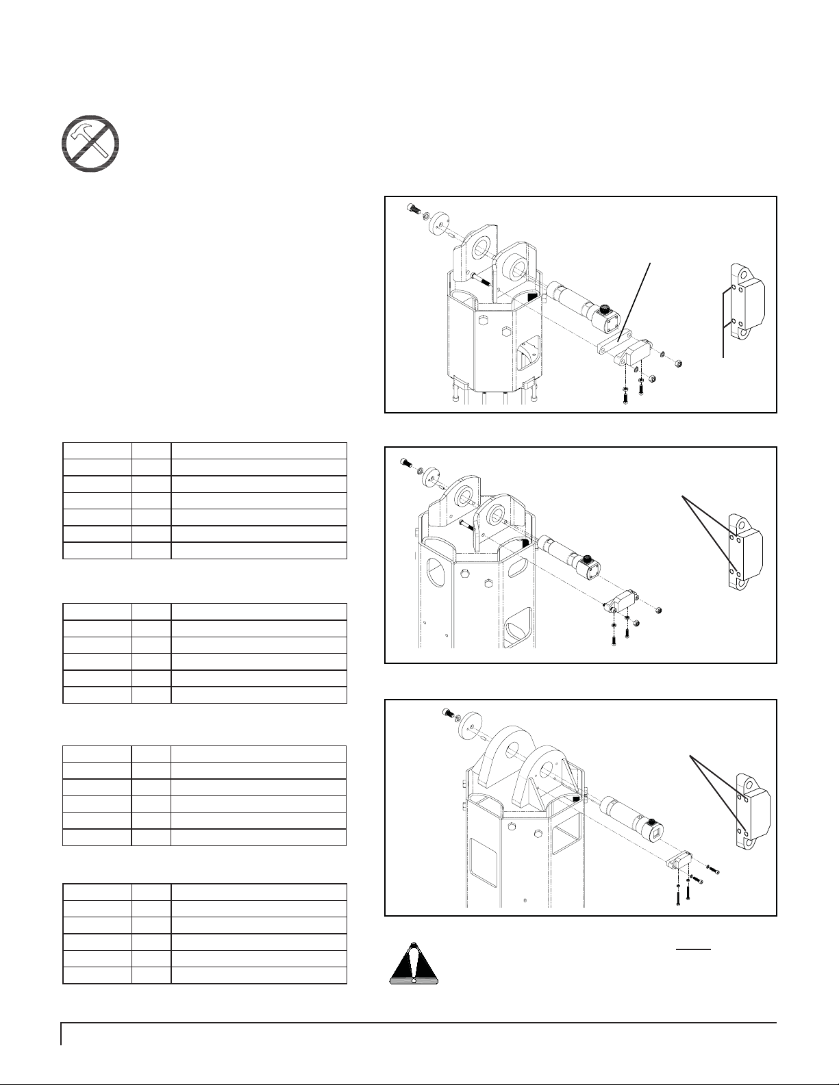
Use the illustrations shown on the right to identify
the correct set-up instructions for your specifi c
Pengo Anchor Drive.
DS-3 & RS-7 Requires:
DT-5, RS-12, RT -9 & RT -12 Requires:
RT-20 Requires:
in which it will be safe to work on during
the pin installation. Remove the existing
Install the Anti-Rotation Block to the
Anchor Drive. The Anti-Rotation Block is
designed to fi t all Pengo Anchor Drives up
PART No. QTY DESCRIPTION
615006 1 ANTI-ROTATION BLOCK
610610 2 SCREW SOCHD M10 X 60mm
615029 1 SPACER CLASS 1
610298 2 NUT HEX LOCK M10
610663 2 SET SCREW 5/16” X 1”
610664 2 JAM NUT 5/16”
PART No. QTY DESCRIPTION
615006 1 ANTI-ROTATION BLOCK
610610 2 SCREW SOCHD M10 X 60mm
610298 2 NUT HEX LOCK M10
174526 2 BOLT HEX 5/16” X 2-1/4”
610664 2 JAM NUT 5/16”
PART No. QTY DESCRIPTION
615006 1 ANTI-ROTATION BLOCK
700534 2 LOCK WASHER 10mm
670175 2 SCREW SOCHD M10 X 40mm
610663 2 SET SCREW 5/16” X 1”
610664 2 JAM NUT 5/16”
Figure 1A
Figure 2A
DS-3 & RS-7 Installation.
Spacer Bar used on
DS-3 & RS-7 Only .
Use this set
of holes for
adjustment
screws.
RS-12, RT -9 & RT -12 Installation.
Use this set of holes for
adjustment screws.
RT -20, RT -30 & RT -40 Installation.
Use this set of holes for
adjustment screws.
RT-20, RT -30 & RT -40 Requires:
PART No. QTY DESCRIPTION
615006 1 ANTI-ROTATION BLOCK
700534 2 LOCK WASHER 10mm
670175 2 SCREW SOCHD M10 X 40mm
174526 2 BOLT HEX 5/16” X 2-1/4”
610664 2 JAM NUT 5/16”
10 PENGO TruLink Manual
Figure 3A
Use of the Anti-Rotation Block is NOT optional.
It must be used in order for the torque and
inclinometer values to be accurate!
ANCHOR DRIVE TRULINK PIN INSTALLATION
NOTE: If your Anchor Drive does not have existing mounting holes located on the Bail Ears:
1) Place the TruLink Pin into the Bail Ears, ensuring the connecting port is facing up and parallel with the Anchor Drive.
2) Position the Anti-Rotation Block on the underside of the pin head (opposite of the connecting port) and mark the location
of the holes. Drill two 7/16” diameter holes. The 30 and 40 series Drives require the holes to be tapped to M10 x 1.5 threads.
Install the appropriate adjustment screws
into the bottom face of the block. Screw the
3
adjustment screws all the way into the block.
The adjustment screws need to be installed before
the block can be bolted to the Bail Ears.
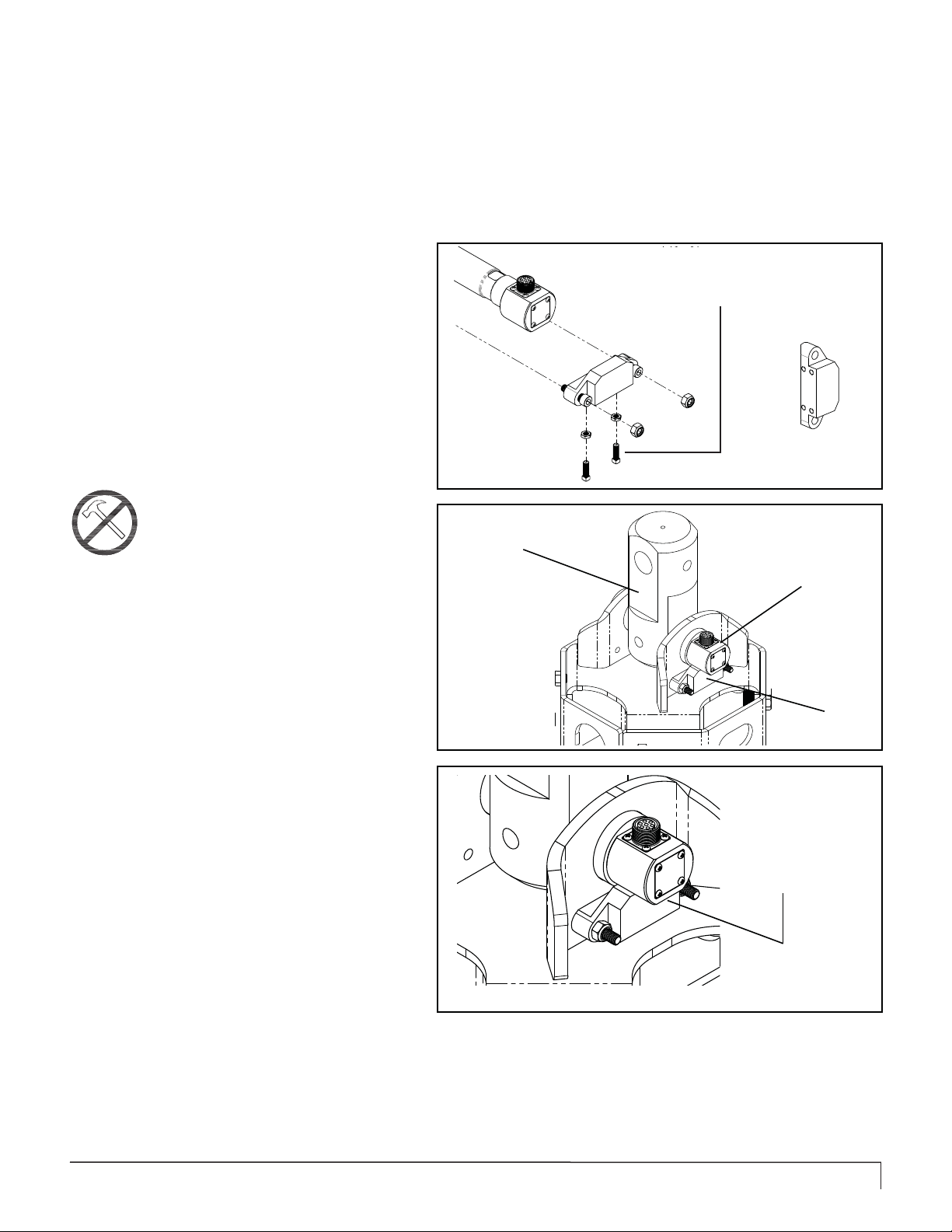
Once the Anti-Rotation Block is in place the
TruLink Pin can now be installed. Position the
4
Link Arm or desired mounting bracket between
the Bail Ears. Install the TruLink Pin with the large
end of the pin facing the front of the Anchor Drive.
See fi gure 5A.
Note: Do NOT hammer or tap the Pin into
place. The Pin should slide easily through
the Bail Ear Bushings.
Figure 4A
Link Arm
Install adjustment screws first
before bolting block to Bail.
ATTENTION!
If the TruLink Pin is not easily installed use the
Installation Rod provided. Instructions on how to use
the Installation Rod are listed on page 12.
Push the Pin into the Drive as far as it will go.
The head of the Pin should align with the Anti-
5
Rotation Block. The opposite end of the Pin
should be fl ush with the outer-edge of the bushing.
The Pin should not protrude past the bushing. See
fi gure 6A.
Install the Pin End Cap by inserting the provided
dowel into the small off center hole in the end
6
of the Cap. Align the dowel and the main hole
of the End Cap with the dowel hole and threaded hole
on the end of the TruLink Pin.
Continue on page 12.
Figure 5A
Figure 6A
TruLink Pin
Anti-Rotation
Block
Bottom of pin
should rest on
the top surface of
the Anti-Rotation
Block.
PENGO TruLink Manual 11
ANCHOR DRIVE TRULINK PIN INSTALLATION
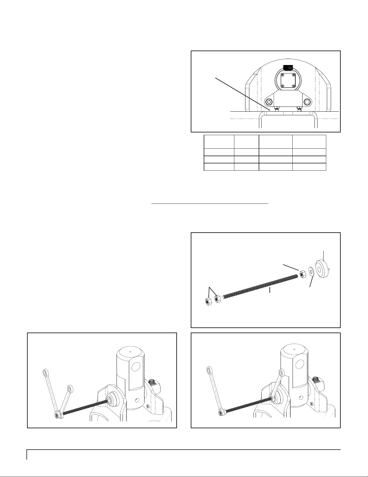
Slide the Anti-Rotation Block tight up against the
head of the TruLink Pin eliminating any gap between
7
the Pin and the block. Unscrew the adjustment
screws until they make contact with the top surface of the
Bail. Make sure the adjustment screws are of equal length
and the block remains parallel with the Bail top plate. See
fi gure 7A.
Secure the End Cap to the TruLink Pin using
8
appropriate class on Pin being installed. The chart lists the
correct tightening torque for the socket head cap screws.
When screws are to be tightened or replaced, refer to this
chart to determine the proper torque.
When installing the TruLink Pin into the Drive it might be necessary to use the Pin-Install Rod. The Install Rod is designed
to draw the TruLink Pin through the Drive ears. The T ruLink Pin can not be forced into place. The Pin should slide easily
through the bushings. When needed use the Install Rod as shown below.
the provided socket cap screw and lock washer.
Tighten screw to the recommended torque for the
Assemble the Installation Rod as shown in fi gure 1B. Note the Pin End Cap will be used in the this step.
Ensure set-screws
make contact with
the top plate of the
Bail.
Figure 7A
Pin
Class
1 1/2” 100 135.5
2 3/4” 340 460.9
3 & 4 1” 800 1084.6
Ft-Lbs = Foot Pounds / Nm = Newton Meters
Screw
Dia
Torque
Ft-Lbs
Torque
N/m
1
Position the two end nuts on the Rod and adjust
according to the amount of Rod required to effectively
2
pull the TruLink Pin through the ears of the Drive.
Using two 7/8” wenches tighten the end nuts against one
another. See fi gure 2B.
Hold the 2nd Nut tight while steadily turning the nut
closest to the End Cap in a clockwise motion. This
3
action will draw the TruLink Pin through the ears of
the Drive. Be careful not to apply too much pressure as this
may damage the threaded hole in the end of the TruLink
Pin. See fi gure 3B.
End Cap
Nut
Nut
Washer
Install Rod
Figure 1B
Figure 3BFigure 2B
When installing large TruLink Pins such as Class 3 and 4 Pins it is highly recommended that the Install Rod be used.
12 PENGO TruLink Manual
TRULINK PIN / CABLE CONNECTION
Depending on the distance from the Anchor Drive to the Display select the appropriate Cable(s). All T ruLink systems have
a Main Cable and an Extension Cable.
Main Cable will connect to the display harness and the TruLink Pin if the length is suffi cient.
Extension Cable (if necessary) connects the Main Cable to the TruLink Pin.
Note: Ensure that the cable(s) have enough “slack” to allow for full range or movement . Most cables can be run next to
the hydraulic hoses.
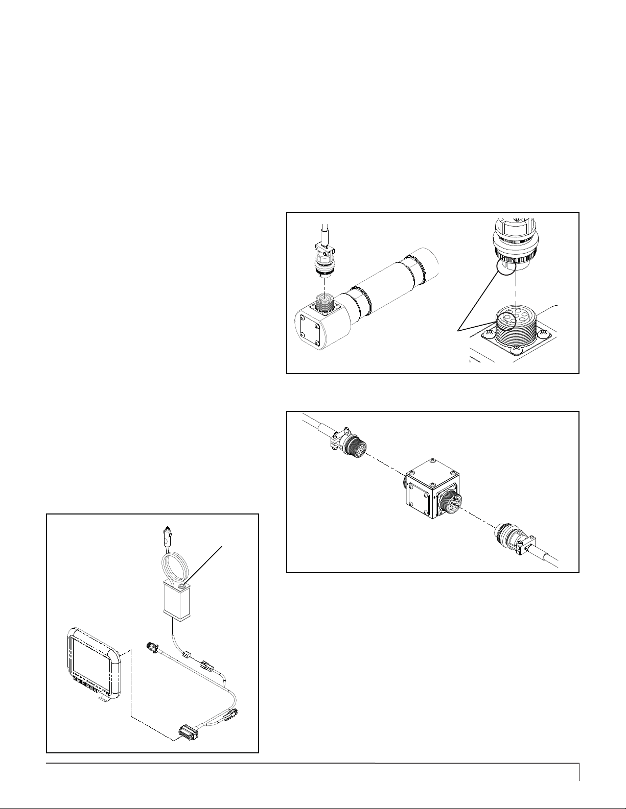
Attach the selected cable to the TruLink
Pin. Be sure to align the pins inside the
1
cable connector with the holes on the
TruLink connecting base. The tab and slot must
align with each other in order to ensure a positive
connection. See fi gure 1C.
On class 3 & 4 TruLink systems it is
1a
a Junction Box and Jib Cable close to the Anchor
Drive will allow for easy disconnect. Using a Jib
Cable near the Anchor Drive will prevent damage
to the Main Cable and is easier to replace in the
event the cable is damaged. See fi gure 2C.
recommended to use the provided
Junction Box and Jib Cable. Installing
Align Slot with T ab
(All Connections)
Figure 1C
Ensure Cable connections are solid and not binding or pinched.
Run all Cables next to the hydraulic hoses
running along prime movers arms and
2
or boom. It is recommended to zip tie
the Cables to the hydraulic hoses. The Cables
should be run in a manner that does not expose
the Cables to excessive heat or pinching.
On / Off
Switch
Figure 2C
BATTERY BACK-UP CABLE CONNECTION
The Battery Back-Up Cable plugs into the Display Power Harness as
shown in fi gure 3D.
Use the ON / OFF switch located on top of the Battery Box to power on
and power off the Display .
PENGO TruLink Manual 13

TRULINK SYSTEM OVERVIEW
Use the illustration below to help familiarize yourself with the various components and overall system layout.
Note: The Jib Cable and Junction box are included
on Class 3 and 4 systems only . On Class 3 and
4 systems it is recommended to use the provided
Junction Box and Jib Cable. Installing a Junction
Box and Jib Cable close to the Anchor Drive will
allow for easy disconnect.
Extension Cable
TruLink
Pin
Jib Cable
Junction
Box
Main Cable
Battery Back-Up
Pin
End Cap
Display Power
Harness
Anti-Rotation
Block
Display
Anchor Drive
14 PENGO TruLink Manual
Job Name: PENGO TEST
Job Number: AQ1356
Customer: PENGO
Location: LAURENS, IOWA
Operator: JON DAVIS
Machine: CAT 320B
Date Time Pile Number Torque Depth X Inclinometer Y Inclinometer
25/01/2013 12:20:12 101 115 0 0 0
25/01/2013 12:20:13 101 222 0 0 0
25/01/2013 12:20:14 101 677 0 0 0
25/01/2013 12:20:15 101 4740 0 0 0
25/01/2013 12:20:16 101 6485 0 0 0
25/01/2013 12:20:17 101 13015 0 0 0
25/01/2013 12:20:18 101 16756 0 0 0
25/01/2013 12:20:19 101 18456 0 0 0
25/01/2013 12:20:20 101 22924 0 0 0
25/01/2013 12:20:21 101 25317 0 0 0
25/01/2013 12:20:22 101 28151 0 0 0
25/01/2013 12:20:23 101 29895 0 0 0
25/01/2013 12:20:24 101 32183 0 0 0
25/01/2013 12:20:25 101 34759 0 0 0
25/01/2013 12:20:26 101 37106 0 0 0
25/01/2013 12:20:27 101 39272 0 0 0
25/01/2013 12:20:28 101 41105 0 0 0
25/01/2013 12:20:29 101 42885 0 0 0
25/01/2013 12:20:30 101 44578 0 0 0
25/01/2013 12:20:31 101 46294 0 0 0
25/01/2013 12:20:32 101 48020 0 0 0
25/01/2013 12:20:33 101 49909 0 0 0
25/01/2013 12:20:34 101 54457 0 0 0
25/01/2013 12:20:35 101 58119 0 0 0
25/01/2013 12:20:36 101 62238 0 0 0
25/01/2013 12:20:37 101 66220 0 0 0
25/01/2013 12:20:38 101 68521 0 0 0
25/01/2013 12:20:39 101 70791 0 0 0
TRULINK DATA CHARTING
DATA CHARTING (RAW DATA)
Below is an example of the raw data recorded by the TruLink system and opened with Microsoft Excel. This data has
not been formatted or manipulated. This is the recorded data in its raw format.
Note: Torque and Depth values will be recorded in the units selected by the user. The default units are Ft/lbs
and Feet.
Date
(DD.MM.YY)
Time
(HH:MM:SS)
(Entered by Operator at beginning of install)
Job Information
T orque V alue
(Ft/Lbs)
(Entered by Operator)
Pile Angle
(Shown in X & Y)
Pile Depth
PENGO TruLink Manual 15
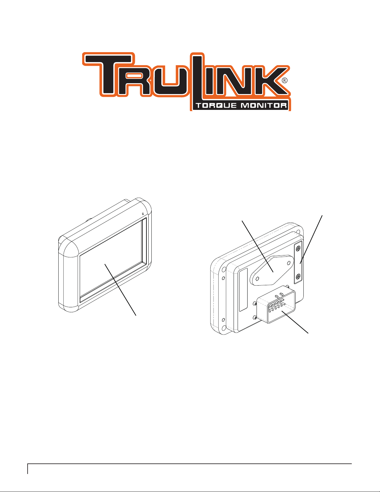
4”
DISPLAY OPERATION SECTION
Mounting Platform
T ouch Screen
4” Touch Screen Display (615011)
This display is available on Class 1 and Class 2 TruLink systems.
USB Port
Communication Port
16 PENGO TruLink Manual
 Loading...