

Pengo LDS User Manual
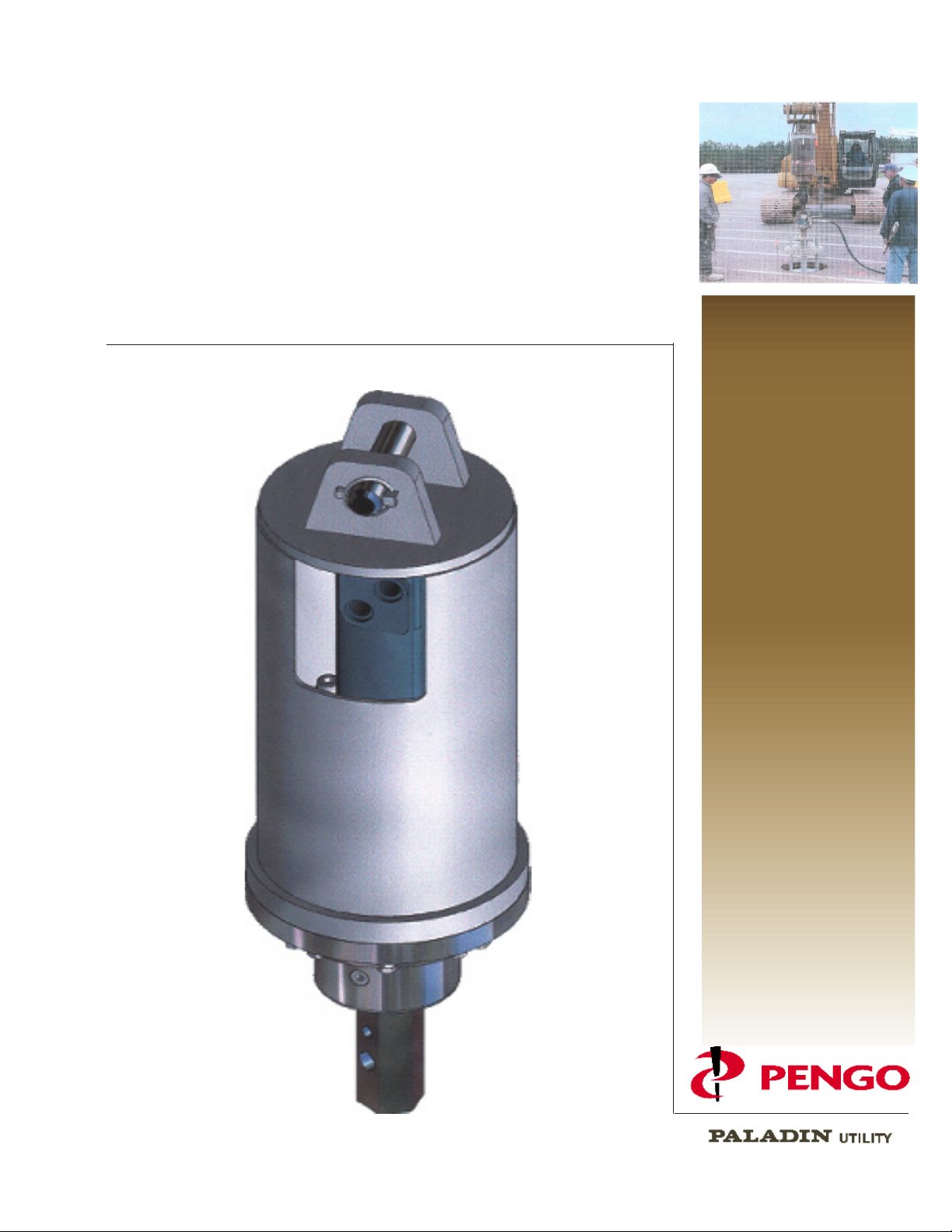
Planetary Auger Drive
LDS/MDS Series
Single Speed
Operators / Parts
Manual
10-7-05, 135471 - Rev A

CONTENTS
To the Purchaser 2
Operator & General Safety 3
Preparation Before Set-up 4
Set Up Instructions 5
Operating Instructions 6
Description Diagram 7
LDS-4K5 Exploded View 8
LDS-4K5 Parts List 9
LDS-6K Exploded View 10
LDS-6K Parts List 11
MDS-8K Exploded View 12
MDS-8K Parts List 13
MDS-12K Exploded View 14
MDS-12K Parts List 15
MDS-17K Exploded View 16
MDS-17K Parts List 17
Lubrication 18
Troubleshooting 19
Warranty Statement 20
TO THE PURCHASER
Thank you for purchasing your new PENGO product.
Pengo products are designed and manufactured to give dependable service, to keep them running
efciently, and for safety reasons ENSURE ALL OPERATORS READ this
OPERATORS/PARTS MANUAL and the RISK MANAGEMENT STRATEGIES MANUAL.
Should you require extra manuals please contact your PENGO DEALER.
Optional extras are available for special applications or extreme conditions; these are noted
throughout each manual.
Contact your PENGO Dealer for any further information or spare parts you may require.
Record your PENGO Product details in the spaces below.
Your PENGO Dealer will need these details to give you prompt, efcient service.
2
PENGO
Serial No.
Flow
Pressure
Weight
Purchased From:
NOTE: As PENGOcontinually strives to improve and increase it’s range of products, the right to
alter specications at any time without notice or obligation, is reserved.
MAX: LPM
MAX:
BAR
KG
Date of Manufacture...../..../....
PENGO
500 East Highway 10, Laurens, IA 50554
PH:(712)845-2540
FAX:(712)845-2497
Date:______/_______/________
OPERATOR and GENERAL SAFETY
KG
The safety of the operator and the safety of everyone within the work area depend on the operator’s knowledge of
the PENGO Product. Before any operation commences with the PENGO Product ENSURE ALL OPERATORS
READ this OPERATORS/PARTS MANUAL and RISK MANAGEMENT STRATEGIES MANUAL and adhere
to all safety guidelines.
CAUTION: Complete a daily inspection prior to operating any PENGO product.
CAUTION: Replace worn parts. Worn parts may endanger safety.
CAUTION: Wear close tting protective clothing and correct safety footwear.
CAUTION: Always ensure onlookers are at least Twenty (20) Feet from all moving parts.
CAUTION: Keep all hands, feet and clothing well away from all moving parts.
CAUTION: Be alert at all times while operating the PENGO product and always ensure you are in complete
control.
CAUTION: Always be aware of any obstructions that may cause injury to the operator or damage the
PENGO product.
3
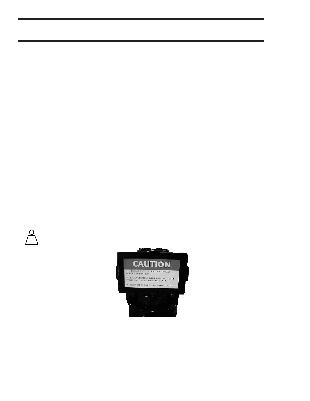
CAUTION: Be aware at all times of any Warning, Caution or other signs within the working area.
NOTE: It is your responsibility as the operator to check for all underground services such as
Gas lines, Electricity, Water lines, Telephone lines, Cable Television etc. before Drilling or
Trenching.
Alert yourself to the weight(s) of the PENGO Product(s) you operate.
Refer Pg 4
Typical Caution Sticker
PREPARATION BEFORE SETUP
This OPERATORS/PARTS MANUAL covers the
following PENGO product.
AUGER DRIVE UNITS
LDS-4K5, LDS-6K
MDS-8K, MDS-12K, MDS-17K
UNIT LDS 4K5 LDS 6K
WEIGHT(lbs) 154 154
UNIT MDS-8K MDS-12K MDS-17K
WEIGHT(lbs) 242 253 463
4
CHECKLIST
To avoid any inconvenience before operation, please check that you have received the
Items (covered in this manual) which you may have ordered.
EXAMPLE
1 x Auger Drive Unit
1 x Swivel Arm
1 x Bail Pin complete with 1 x Spring Clip.
1 x Auger Pin with 1 x Spring Clip.
2 x Hydraulic Hoses.
1 x Frame (For mounting Auger Drive Unit to Parent Machine)
Augers
Wearparts
SET UP INSTRUCTIONS
KG
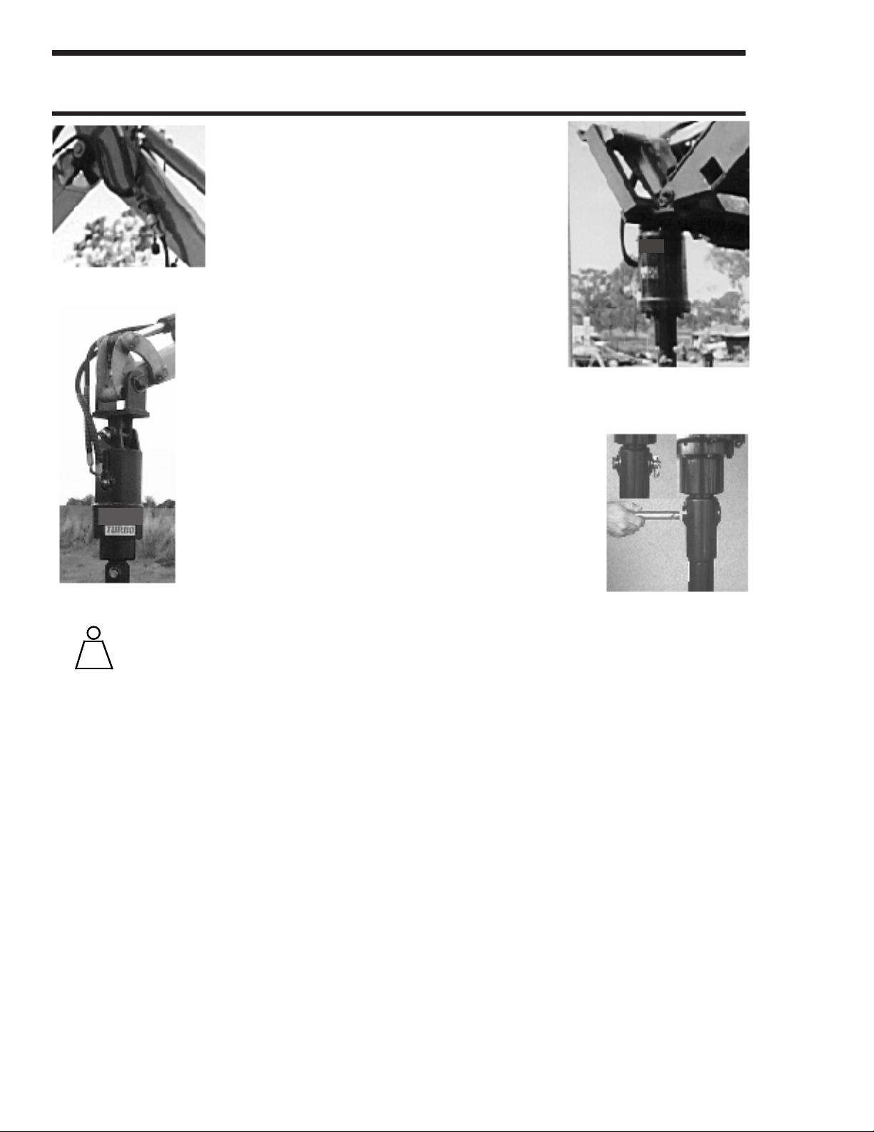
The PENGO Earth Auger Drive Unit
receives its Hydraulic oil ow and
pressure from the Parent Machine
through the Auxiliary Hydraulic
(Attachment) Circuit via two Quick
Release Couplers normally located
near the end of the Loader arms,
Fig 1
Excavator Dipper or Truck Crane
Booms etc.
Mounting Frames are attached to
the Bucket Attaching Points on
Loader arms and Excavators. On
Truck Cranes a Linkage is normally
located between the Hook Pin and the
PENGO Earth Auger Drive Unit.
FIG 2: Typical mounting for
Excavators.
FIG 3: Typical mounting for Skid
5
Fig 3
Fig 2
CAUTION: Alert yourself to the weight(s) of the PENGO product(s) Refer Pg 4
You operate. Do not exceed your machine operating weight
or lifting capacity. (Refer to your machine manual)
Ensure your machines Flow & Pressures do not exceed the maximum rated Flow & Pressures
of the PENGO Earth Auger Drive Unit. (Refer Pg 2 To the Purchaser)
(1) Fit Mounting Frame (Refer Above)
(2) Fit PENGO Earth Auger Drive Unit using Bail and Pins.
(3) Hook up hoses to Auxiliary Hydraulic Circuit. ENGINE MUST BE SHUT OFF.
(4) Check that the drilling rotation on PENGO Earth Auger Drive Unit is clockwise.
NOTE: Two-way ow is required for anticlockwise rotation.
(5) To assure optimum Hydraulic Motor life, run new PENGO Earth Auger Drive Unit for one hour
on approx. 1/3rd RPM before application of full load.
(6) Fit Auger. (See Fig 4) Use only genuine PENGO Auger Pin and Spring Clip.
REMOVAL PROCEDURE: Reversal of Set up Instructions.
Fig 4
OPERATING INSTRUCTIONS 6
Before operating, always ensure that the PENGO Earth Auger Drive Unit and Auger are tted
correctly to the parent machine. (Refer to Set up Instructions Pg 5).
CAUTION: Do not operate on excessive slopes, embankments or near edges of excavations.
When travelling or manoeuvring Parent Machine to the required drilling area, reduce ground speed
to prevent the Earth Auger Drive Unit and Auger from swinging.
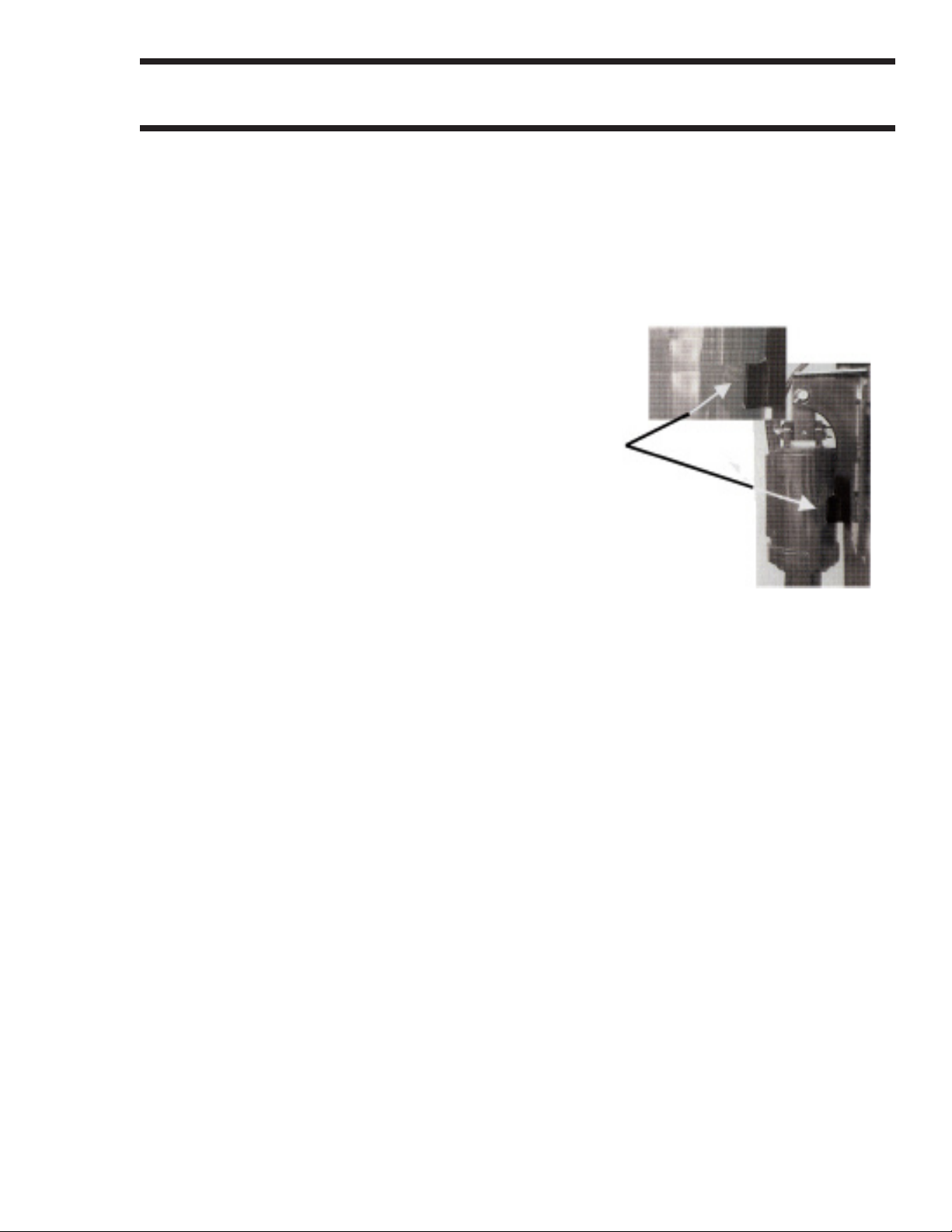
NOTE: Some mounting Frames are tted with a support
bracket. When tted ensure support bracket locates the
Earth Auger Drive Unit and Auger during travelling or
manoeuvring (See Photo, Typical for Skid Steer Loaders)
To commence drilling, locate Auger Pilot (on pre marked spot)
and engage machine auxiliary lever to rotate the Auger in a
clockwise direction.
Lower the machine arm(s) to push the Auger into the ground. The harder the ground the more down
pressure you will need.
NOTE: Do not continually stall the Earth Auger Drive Unit. Continual stalling may cause excessive
heating of the hydraulic system.
As the Auger digs into the ground , the machine arm(s) may travel through an arc. You may therefore
have to continually reposition the Earth Auger Drive Unit or Parent machine to drill vertically.
Do not drill the Auger deep into the ground in one operation. Continually clearing the hole during
drilling will facilitate a faster and easier operation.
NOTE: Extension shafts are available for extra depth.
Disengage machine auxiliary lever and rest Earth Auger Drive Unit and Auger on the ground before
making any adjustments or leaving the Parent Machine.

DESCRIPTION DIAGRAM 7
 Loading...