

Pengo DT-5 User Manual

Manual ID: Drive Manual RT Series.indd
Release Date: June, 18 2015
Owner’s Manual
Parts Manual
Printed in the USA
Safety Precautions
Operating Instructions
Maintenance
TWO SPEED MODELS:
dT-5 dT-15 rT-9 rT-12 rT-20
rT-30 rT-40
800-599-0211 l www.pengoattachments.com l PENGO: 500 East Highway 10, Laurens, IA 50554, USA
Two Speed (DT & RT) Series Manual 1

PREFACE
This manual is used to familiarize you with safety , assembly, operation, adjustment, troubleshooting, and maintenance.
Read and follow the recommendations in this manual to ensure safe and effi cient operation. Keep this manual with the
attachment at all times for future reference.
We want you to be completely satisfi ed with your new product, feel free to contact your local Authorized Service Dealer for
help with service, replacement parts, or any other information you may require. If you need assistance in locating a dealer,
visit our web site at www.pengoattachments.com or call customer service at 1-800-599-021 1.
Whenever you contact your Authorized Service Dealer or PENGO, always have the model number and serial number of
your product available. These numbers will help provide exact information about your specifi c product. You will fi nd the
model and serial numbers on an ID plate located on the product.
The descriptions and specifi cations in this manual are subject to change without notice. PENGO reserves the right to improve
products. Some product improvements may have taken place after this manual was printed. For the latest information on
PENGO attachments, visit our web site at www.pengoattachments.com or call customer service at 1-800-599-021 1.
Thank you for buying and using PENGO attachments!
TABLE OF CONTENTS
Preface / Table of Contents ................................................................................................................................. 2
Table of Contents Continued ............................................................................................................................... 3
Safety Statements ............................................................................................................................................ 4
General Precautions ........................................................................................................................................... 5
General Precautions Cont. .................................................................................................................................. 6
General Precautions Cont. (811 Information) / Serial Number Identifi cation ....................................................... 7
Product / Equipment Precautions ....................................................................................................................... 8
Safety Decal Information ..................................................................................................................................... 9
Product Specifi cations DT-5 / DT-15 ................................................................................................................. 10
Product Specifi cations RT-9 / RT-12 ..................................................................................................................11
Product Specifi cations RT-20 / RT-30 ............................................................................................................... 12
Product Specifi cations RT-40 ............................................................................................................................. 13
Typical Attachment Connections ...................................................................................................................... 14
Blank ........................................................................................................................................... 15
Prime Mover Operating Positions (skid loader) .................................................................................................. 16
Prime Mover Operating Positions (skid loader) .................................................................................................. 17
Prime Mover Operating Positions (excavator) ................................................................................................... 18
Prime Mover Operating Positions (excavator) .................................................................................................... 19
Set-Up / Hydraulic System Hook-Up / Operating Procedures ............................................................................ 20
Operating Procedures Cont. / Maintenance Instructions ................................................................................... 21
Maintenance Instructions / Storage Instructions ................................................................................................ 22
Checking and Changing Gear Oil ...................................................................................................................... 23
Troubleshooting ........................................................................................................................................... 24
Two Speed Hydraulic Motor Information ........................................................................................................... 25
Two Speed Hydraulic Motor Information ........................................................................................................... 26
Blank ........................................................................................................................................... 27
Parts Breakdown DT-5 ...................................................................................................................................... 28
Gearbox Breakdown DT-5 ........................................................................................................................... 29
Parts Breakdown DT-15 .................................................................................................................................... 30
Gearbox Breakdown DT-15 ............................................................................................................................... 31
Parts Breakdown RT-9 ......................................................................................................................................32
Gearbox Breakdown RT-9 ................................................................................................................................. 33
2 Two Speed (DT & RT) Series Manual

TABLE OF CONTENTS CONT.
Parts Breakdown RT-12 ....................................................................................................................................34
Gearbox Breakdown RT-12 ............................................................................................................................... 35
Parts Breakdown RT-20 ....................................................................................................................................36
Gearbox Breakdown RT-20 ............................................................................................................................... 37
Parts Breakdown RT-30 ....................................................................................................................................38
Gearbox Breakdown RT-30 ............................................................................................................................... 39
Parts Breakdown RT-40 (Old Model) ................................................................................................................. 40
Gearbox Breakdown RT-40 (Old Model) ........................................................................................................... 41
Parts Breakdown RT-40 (New Model) ................................................................................................................ 42
Gearbox Breakdown RT-40 (New Model) .......................................................................................................... 43
Pengo Warranty Policy ....................................................................................................................................... 44
Torque Chart for Common Bolts ........................................................................................................................ 45
Two Speed (DT & RT) Series Manual 3
SAFETY STATEMENTS
DANGER
WARNING
CAUTION
WARNING
THIS STATEMENT IS USED WHERE SERIOUS INJURY OR DEATH WILL RESULT IF THE
INSTRUCTIONS ARE NOT FOLLOWED PROPERLY.
THIS STATEMENT IS USED WHERE SERIOUS INJURY OR DEATH COULD RESULT IF
THE INSTRUCTIONS ARE NOT FOLLOWED PROPERLY.
THIS STATEMENT IS USED WHERE MINOR INJURY COULD RESULT IF THE
INSTRUCTIONS ARE NOT FOLLOWED PROPERLY.
THIS SYMBOL BY ITSELF OR USED WITH A SAFETY SIGNAL WORD THROUGHOUT
THIS MANUAL IS USED TO CALL YOUR ATTENTION TO INSTRUCTIONS INVOLVING
YOUR PERSONAL SAFETY OR THE SAFETY OF OTHERS. FAILURE TO FOLLOW
THESE INSTRUCTIONS CAN RESULT IN INJURY OR DEATH.
READ MANUAL PRIOR TO INSTALL
Improper installation, operation, or maintenance of the equipment could result in serious
injury or death. Operators and maintenance personnel should read this manual as well as
all manuals related to this equipment. FOLLOW ALL SAFETY INSTRUCTIONS IN THIS
MANUAL.
WARNING
WARNING
READ AND UNDERSTAND ALL SAFETY STATEMENTS
Read all safety decals and safety statements in all manuals prior to operating or working
on this equipment. Know and obey all OSHA regulations, local laws and other professional
guidelines for your operation. Know and follow good work practices when assembling,
maintaining, repairing, mounting, removing or operating this equipment.
KNOW YOUR EQUIPMENT
Know your equipment’s capabilities, dimensions and operations before operating. Visually
inspect your equipment before you start, and never operate equipment that is not in proper
working order with all safety devices intact. Check all hardware to assure it is tight. Make
certain that all locking pins, latches, and connection devices are properly installed and
secured. Remove and replace any damaged, fatigued or excessively worn parts. Make
certain all safety decals are in place and are legible. Keep decals clean, and replace them if
they become worn and hard to read.
DO NOT MODIFY EQUIPMENT
Modifi cations may weaken the integrity of the equipment and may impair the functions, safety,
life, and performance of the equipment. When making repairs, use only the manufactures
genuine parts, following authorized instructions. Other parts may be substandard in fi t and
quality.
PREPARE FOR EMERGENCIES
• Be prepared if a fi re starts.
• Keep a fi rst aid kit near by when operating equipment.
4 Two Speed (DT & RT) Series Manual

GENERAL PRECAUTIONS
WARNING
CAUTION
WARNING
OPERA TOR SAFETY
• Protective clothing and equipment should be worn at all times.
• Wear protective clothing and equipment appropriate for the job. Avoid loose fi tting clothing.
• Prolonged exposure to excessive noise can cause hearing loss. Wear suitable hearing protection
such as ear plugs.
• Operating equipment safely requires the full attention of the operator. Avoid distractions.
• Do not operate the unit when you are tired, ill or under the influence of alcohol, drugs or
medication.
• Never let a minor or inexperienced person operate the unit.
• Keep all body parts away from the drilling bit at all times.
• Inspect the area to be drilled before operation. Remove objects which can be thrown or become
entangled.
• DO NOT operate the Drive attachment in areas where carbon monoxide fumes can accumulate.
PRODUCT SAFETY
• Inspect the entire product before operation.
• Replace parts that are cracked, chipped or damaged in any way before operation.
• Keep others away when making any adjustments to the unit.
• Damage to the Auger Drive and auger bit can result if the prime mover moves while the auger is
still in the hole.
PRACTICE SAFE MAINTENANCE
• Use proper tools and equipment when conducting maintenance.
• Work in a clean dry area.
• Inspect all parts. Be sure parts are in good working condition and installed properly .
• Remove build up of grease, oil or any debris.
• Remove all tools and unused parts from equipment before beginning operation.
WARNING
WARNING
WARNING
BE ALERT ON THE JOB SITE
Tragic accidents can occur if the operator is not alert to the presence of bystanders. Children in
particular are often attracted to machinery and work activity . Never assume that children will remain
where you last saw them. BE ALER T and turn the equipment off if children enter the work area. Keep
children out of the work area and under supervision of another responsible adult.
DRILLING SAFETY
• Inspect the area to be drilled before operation. Remove objects which can be thrown or become
entangled. Be alert when drilling in locations where any type of landscaping fabric / mat may be
present. The material can be rapidly drawn into the point of operation, possibly causing injury or
death to anyone standing on or near the fabric.
• Keep all parts of your body away from the drilling bit when operating the unit.
• DO NOT operate the Auger Drive when the auger bit is more then 12” (305mm) above ground. The
auger bit may bind and cause injury to the operator and damage to the equipment.
• While the auger bit is rotating, DO NOT attempt to manually guide the auger to a location.
• Ensure that overhead power / utility lines do not come into contact with the Drive attachment.
• DO NOT use a shovel or any other object to remove material from the auger bit or the hole while
the Drive attachment is in use.
UNDERGROUND HAZARDS
It is the responsibility of the operator to know where buried power, gas, telephone, and other utilities
are at in the work area. This may lead to shock or an explosion. Have the work area marked for buried
lines and do not dig in marked areas set by your local municipals. Striking a hard object underground
with the auger turning can result in the slowing or stopping of the auger.
Two Speed (DT & RT) Series Manual 5
GENERAL PRECAUTIONS - CONTINUED
WARNING
WARNING
WARNING
LOWER OR SUPPORT RAISED EQUIPMENT
Do not work under raised booms without supporting them. Do not use support material
made of concrete blocks, logs, buckets, barrels, or any other material that could
suddenly collapse or shift positions. Make sure support material is solid, not decayed,
warped, twisted, or tapered. Lower booms to ground level or on blocks. Lower booms
and attachments to the ground before leaving the cab or operator’s station. Whenever the boom
structure must be raised for attachment installation or servicing block ensure the boom locking
devices (if equipped) are deployed to prevent the accidental lowering of boom structures.
NEVER PLACE ANY BODY PART BETWEEN THE PRIME MOVER CHASSIS AND THE BOOM
STRUCTURE! Refer to the operating and maintenance instructions provided by the prime mover
manufacturer for specifi c information.
USE CARE WITH SILICA DUST DURING OPERA TION
Concrete and masonry products contain silica sand. Quartz, which is a form of silica and the most
common mineral in the earths crust, is associated with many types of rock. Some activities that
silica dust may be present in the air include demolition, sweeping, loading, sawing, hammering,
drilling, or planing of rock, concrete or masonry .
It is recommended to use dust suppression, dust collection or personal protective equipment
during the operation of any attachment that may cause high levels of silica dust.
The NIOSH recommended exposure limit for respirable crystalline silica is 0.05 mg/m3 as a time-
weighted average for up to 10 hours/day during a 40-hour workweek [NIOSH 1974].
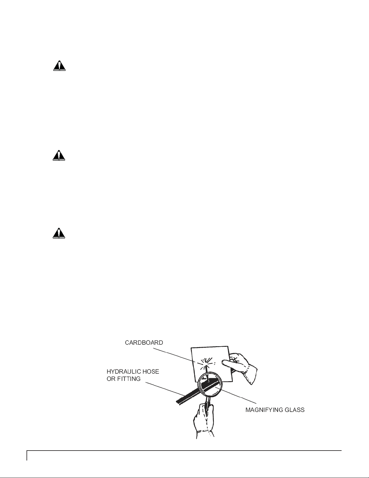
USE CARE WITH HYDRAULIC FLUID PRESSURE
Hydraulic fl uid under pressure can penetrate the skin and cause serious injury or
death. Hydraulic leaks under pressure may not be visible. Before connecting or
disconnecting hydraulic hoses, read your prime mover’s operator’s manual for
detailed instructions on connecting and disconnecting hydraulic hoses or fi ttings.
• Keep unprotected body parts, such as face, eyes, and arms as far away as
possible from a suspected leak. Flesh injected with hydraulic fl uid may develop
gangrene or other permanent disabilities.
• If injured by injected fl uid, see a doctor at once. If your doctor is not familiar with
this type of injury , ask him to research it immediately to determine proper treatment.
• Wear safety glasses, protective clothing, and use a piece of cardboard or wood
when searching for hydraulic leaks. DO NOT USE YOUR HANDS! SEE ILLUSTRA TION.
6 Two Speed (DT & RT) Series Manual

GENERAL PRECAUTIONS - CONTINUED
One easy phone call to 811 starts the process to get your underground utility lines marked for free. When you call
811 from anywhere in the country (USA), your call will be routed to your local One Call Center. Local One Call Center
operators will ask you for the location of your digging job and route your call to affected utility companies. Your utility
companies will then send a professional locator to your location to mark your lines within a few days. Once your
underground lines have been marked, you will know the approximate location of your utility lines and can dig safely,
because knowing what’s below protects you and your family.
Every state has different rules and regulations governing digging, some stricter than others. In addition, 62 separate
One Call Centers serve different areas of the country; now 811 will connect you directly to your local one call center.
For more information go to www.call811.com
Always call 811 before starting any digging project!
**Customers outside the United States need to contact their local utility company for underground safety regulations
specifi c to the area.
SERIAL NUMBER IDENTIFICATION
Its important to make the correct reference to the serial number of the unit when making repairs
or ordering parts. The serial number plate will be located near the top of the Anchor / Auger Drive
attachment. Below is an example of the serial number plate.
Figure 1
Two Speed (DT & RT) Series Manual 7

PRODUCT / EQUIPMENT PRECAUTIONS
CAUTION
WARNING
WARNING
PRIME MOVER LIFT CAPACITY
Alert yourself to the weight of the Drive Unit. DO NOT exceed the recommended lift capacity of
the prime mover. Refer to your prime mover’s owners manual for suggested lift capacity and lift
considerations.
PRIME MOVER / ATTACHMENT INSTALLATION
Ensure all connection pins, fasteners and latches are properly secured. Ensure that the mounting
frame / attachment mounting plate is rigidly secured to the prime mover. Improper installation
can result in product damage, personal injury and death.
Ensure all hydraulic hose assemblies are of adequate length and have enough slack for full Drive
attachment movement. Failure to provide adequate length hydraulic hoses can result in hose
rupturing. A hydraulic hose rupture can result in product damage, personal injury and death.
OPERATING THE PRIME MOVER
Avoid steep hillside operation, which could cause the prime mover to overturn. Consult
your prime mover operator’s and safety manuals for maximum incline allowable.
TRANSPORTING THE DRIVE A TT ACHMENT
• Travel only with the Drive attachment in a safe transport position to prevent uncontrolled
swinging.
• T ether the Drive attachment with a chain, if necessary, to prevent uncontrolled swinging of the auger
when moving from hole to hole.
• Remove the earth auger or helical anchor from the Drive attachment before transporting to and
from the job site.
• Use extreme care during transport to prevent contact between the Drive attachment and bystanders
or solid objects. Contact with the Drive attachment could cause serious damage, injury or death.
• Never operate the Drive attachment while transporting.
• Drive slowly over rough ground and on slopes. Position the Drive attachment as low to the ground
as possible maintaining a low center of gravity .
CAUTION
8 Two Speed (DT & RT) Series Manual
DRIVE ATTACHMENT SIDE LOADING
Side loading is NOT recommended. Excessive side loading can cause output shaft defl ection and or
failure. A void excessive side loading to prevent possible instantaneous output shaft failure. Such a
failure could result in injury from disconnected parts and or being hit by the Drive attachment causing
serious injury or death.

SAFETY DECAL INFORMATION
SAFETY DECALS
This unit comes equipped with all safety decals in place. They are designed to help you safely operate
your unit. Read and follow all safety decals.
• Keep all safety decals clean and legible at all times.
• Replace safety decals that are missing or have become illegible.
• Safety decals are available from your distributor or manufacture.
• Some parts installed during repair may require safety decals to be affi xed to the replacement part.
When ordering the replacement part(s) be sure the correct safety decal(s) are included in your order.
INST ALLING SAFETY DECALS
• Clean the desired area with warm soapy water.
• Decide on exact position before you remove the backing paper.
• Peel backing paper from decal. Press fi rmly on the surface.
• Air pockets can be pierced with a pin and smoothed.
T ypical Decals used on Pengo Anchor / Auger Drive Attachments
350247
350266
Figure 2
Two Speed (DT & RT) Series Manual 9

PRODUCT SPECIFICATIONS
AUGER DRIVE MODEL
dt-5
TOTAL UNIT WEIGHT 645 LBS / 292 Kg
HYDRAULIC MOTOR INFORMATION
Displacement 2.98 cu/in (97.6cc)
Motor Type
Motor Output Shaft 1-1/4" Spline 14T
Motor Mount SAE - C 4 Bolt
Motor Ports 1-5/8" - 12 UN-2B
Cross Over Pressure Relief Set @ 3100 psi
PLANETARY GEARBOX INFORMATION
Gearbox Type Planetary Two Stage
Reduction Ratio 25.36:1
Output Shaft 2-1/2" Hex
Oil Capacity 2.0 Gallons
Oil Type SAE 80W90 GL-5
Shaft Pull Out (lbs.) 22,500 lbs.
REFERENCE TORQUE CHART
Pressure PSI (Bar)
1600 (110) 2629 1314
1800 (124) 2958 1478
2000 (137) 3287 1643
2200 (151) 3615 1807
2400 (165) 3943 1971
2600 (179) 4272 2136
2800 (193) 4601 2300
3000 (206) 4930 2465
REFERENCE SPEED CHART
Flow GPM (Liter)
20 (75) 25 50
25 (95) 31 63
30 (113) 38 75
35 (132) 44 88
40 (151) 50 100
High Torque (ft/lbs) Low Torque (ft/lbs)
Low Spd (rpm) High Spd (rpm)
Two Speed Bi-Directional
AUGER DRIVE MODEL
dt-15
TOTAL UNIT WEIGHT 825 LBS / 374 Kg
HYDRAULIC MOTOR INFORMATION
Displacement 17.8 cu/in (293cc)
Motor Type
Motor Output Shaft 1-1/4" Spline 14T
Motor Mount SAE - C 4 Bolt
Motor Ports 1-5/8" - 12 UN-2B
Cross Over Pressure Relief Set @ 3100 psi
PLANETARY GEARBOX INFORMATION
Gearbox Type Planetary Two Stage
Reduction Ratio 26.52:1
Output Shaft 3" Hex
Oil Capacity 3.0 Gallons
Oil Type SAE 80W90 GL-5
Shaft Pull Out (lbs.) 22,500 lbs.
REFERENCE TORQUE CHART
Pressure PSI (Bar)
1600 (110) 8254 4127
1800 (124) 9287 4643
2000 (137) 10318 5159
2200 (151) 11350 5674
2400 (165) 12382 6191
2600 (179) 13414 6707
2800 (193) 14445 7223
3000 (206) 15478 7738
REFERENCE SPEED CHART
Flow GPM (Liter)
20 (75) 8 16
30 (113) 12 24
40 (151) 16 32
50 (190) 20 40
High Torque (ft/lbs) Low Torque (ft/lbs)
Low Spd (rpm) High Spd (rpm)
Two Speed Bi-Directional
Two speed models must have a minimum of 20GPM.
Output speed and torque specifi cations are NOT listed at 100% effi ciency. Maximum effi ciencies have been applied to the torque
and speed charts according to the manufacturers recommendations. Speed and torque output are dependent on the overall
system effi ciencies associated with the prime movers hydraulic system. When the purchaser is determining criteria for specifi c
applications please contact Pengo. Pengo has made every attempt to present accurate and suitable information published on this
document. This document should be used for information and comparative purposed only. When application specifi c information is
required, please contact Pengo.
Pengo continually looks for new ways to improve its products. Therefore, Pengo reserves the right to make changes to our
products and specifi cations without notice.
10 Two Speed (DT & RT) Series Manual

PRODUCT SPECIFICATIONS
AUGER DRIVE MODEL
rt-9
TOTAL UNIT WEIGHT 645 LBS / 292 Kg
HYDRAULIC MOTOR INFORMATION
Displacement
Motor Type
Motor Output Shaft
Motor Mount
Motor Ports
Cross Over Pressure Relief
PLANETARY GEARBOX INFORMATION
Gearbox Type Planetary Two Stage
Reduction Ratio 25.36:1
Output Shaft 2-1/2" Hex
Oil Capacity 2.0 Gallons
Oil Type SAE 80W90 GL-5
Shaft Pull Out (lbs.) 22,500 lbs.
REFERENCE TORQUE CHART
Pressure PSI (Bar)
1600 (110) 5253 2626
1800 (124) 5910 2954
2000 (137) 6567 3283
2200 (151) 7223 3611
2400 (165) 7880 3940
2600 (179) 8536 4268
2800 (193) 9193 4596
3000 (206) 9850 4925
REFERENCE SPEED CHART
Flow GPM (Liter)
20 (75) 13 25
30 (113) 19 38
40 (151) 25 50
50 (190) 31 63
High Torque (ft/lbs) Low Torque (ft/lbs)
Low Spd (rpm) High Spd (rpm)
11.9 cu/in (195cc)
Two Speed Bi-Directional
1-1/4" Spline 14T
SAE - C 4 Bolt
1-5/8" - 12 UN-2B
Set @ 3100 psi
AUGER DRIVE MODEL
rt-12
TOTAL UNIT WEIGHT 655 LBS / 297 Kg
HYDRAULIC MOTOR INFORMATION
Displacement
Motor Type
Motor Output Shaft
Motor Mount
Motor Ports
Cross Over Pressure Relief
PLANETARY GEARBOX INFORMATION
Gearbox Type Planetary Two Stage
Reduction Ratio 25.36:1
Output Shaft 2-1/2" Hex
Oil Capacity 2.0 Gallons
Oil Type SAE 80W90 GL-5
Shaft Pull Out (lbs.) 22,500 lbs.
REFERENCE TORQUE CHART
Pressure PSI (Bar)
1600 (110) 6576 3068
1800 (124) 7398 3451
2000 (137) 8220 3835
2200 (151) 9042 4219
2400 (165) 9864 4603
2600 (179) 10686 4986
2800 (193) 11508 5369
3000 (206) 12330 5753
REFERENCE SPEED CHART
Flow GPM (Liter)
20 (75) 10 21
30 (113) 15 31
40 (151) 21 41
50 (190) 26 51
High Torque (ft/lbs) Low Torque (ft/lbs)
Low Spd (rpm) High Spd (rpm)
14.9 cu/in (244cc)
Two Speed Bi-Directional
1-1/4" Spline 14T
SAE - C 4 Bolt
1-5/8" - 12 UN-2B
Set @ 3100 psi
Two speed models must have a minimum of 20GPM.
Output speed and torque specifi cations are NOT listed at 100% effi ciency. Maximum effi ciencies have been applied to the torque
and speed charts according to the manufacturers recommendations. Speed and torque output are dependant on the overall
system effi ciencies associated with the prime movers hydraulic system. When the purchaser is determining criteria for specifi c
applications please contact Pengo. Pengo has made every attempt to present accurate and suitable information published on this
document. This document should be used for information and comparative purposed only. When application specifi c information is
required, please contact Pengo.
Pengo continually looks for new ways to improve its products. Therefore, Pengo reserves the right to make changes to our
products and specifi cations without notice.
Two Speed (DT & RT) Series Manual 11

PRODUCT SPECIFICATIONS
AUGER DRIVE MODEL
rt-20
TOTAL UNIT WEIGHT 855 LBS / 387 Kg
HYDRAULIC MOTOR INFORMATION
Displacement
Motor Type
Motor Output Shaft
Motor Mount
Motor Ports
Cross Over Pressure Relief
PLANETARY GEARBOX INFORMATION
Gearbox Type Planetary Three Stage
Reduction Ratio 60.56:1
Output Shaft 3" Hex
Oil Capacity 3.0 Gallons
Oil Type SAE 80W90 GL-5
Shaft Pull Out (lbs.) 45,000 lbs.
REFERENCE TORQUE CHART
Pressure PSI (Bar)
1600 (110) 12086 6043
1800 (124) 13597 6798
2000 (137) 15108 7554
2200 (151) 16618 8309
2400 (165) 18129 9064
2600 (179) 19640 9820
2800 (193) 21151 10575
3000 (206) 22662 11331
REFERENCE SPEED CHART
Flow GPM (Liter)
20 (75) 5 10
30 (113) 8 15
40 (151) 10 20
50 (190) 13 25
High Torque (ft/lbs) Low Torque (ft/lbs)
Low Spd (rpm) High Spd (rpm)
11.9 cu/in (195cc)
Two Speed Bi-Directional
1-1/4" Spline 14T
SAE - C 4 Bolt
1-5/8" - 12 UN-2B
Set @ 3100 psi
AUGER DRIVE MODEL
rt-30
TOTAL UNIT WEIGHT 1220 LBS / 553 Kg
HYDRAULIC MOTOR INFORMATION
Displacement
Motor Type
Motor Output Shaft
Motor Mount
Motor Ports
Cross Over Pressure Relief
PLANETARY GEARBOX INFORMATION
Gearbox Type Planetary Three Stage
Reduction Ratio 69.7:1
Output Shaft 4" Square
Oil Capacity 3.1 Gallons
Oil Type SAE 80W90 GL-5
Shaft Pull Out (lbs.) 60,000 lbs.
REFERENCE TORQUE CHART
Pressure PSI (Bar)
1600 (110) 16250 8125
1800 (124) 18281 9140
2000 (137) 20312 10156
2200 (151) 22344 11171
2400 (165) 24375 12187
2600 (179) 26407 13203
2800 (193) 28438 14218
3000 (206) 30470 15234
REFERENCE SPEED CHART
Flow GPM (Liter)
20 (75) 4 8
30 (113) 6 11
40 (151) 8 15
50 (190) 9 19
High Torque (ft/lbs) Low Torque (ft/lbs)
Low Spd (rpm) High Spd (rpm)
13.9 cu/in (227cc)
Two Speed Bi-Directional
1-1/4" Spline 14T
SAE - C 4 Bolt
1-5/8" - 12 UN-2B
Set @ 3100 psi
Two speed models must have a minimum of 20GPM.
Output speed and torque specifi cations are NOT listed at 100% effi ciency. Maximum effi ciencies have been applied to the torque
and speed charts according to the manufacturers recommendations. Speed and torque output are dependent on the overall
system effi ciencies associated with the prime movers hydraulic system. When the purchaser is determining criteria for specifi c
applications please contact Pengo. Pengo has made every attempt to present accurate and suitable information published on this
document. This document should be used for information and comparative purposed only. When application specifi c information is
required, please contact Pengo.
Pengo continually looks for new ways to improve its products. Therefore, Pengo reserves the right to make changes to our
products and specifi cations without notice.
12 Two Speed (DT & RT) Series Manual

PRODUCT SPECIFICATIONS
AUGER DRIVE MODEL
rt-40
TOTAL UNIT WEIGHT 1440 LBS / 653 Kg
HYDRAULIC MOTOR INFORMATION
Displacement
Motor Type
Motor Output Shaft
Motor Mount
Motor Ports
Cross Over Pressure Relief
PLANETARY GEARBOX INFORMATION
Gearbox Type Planetary Three Stage
Reduction Ratio 90.39:1
Output Shaft 130mm Square
Oil Capacity 3.7 Gallons
Oil Type SAE 80W90 GL-5
Shaft Pull Out (lbs.) 60,000 lbs.
REFERENCE TORQUE CHART
Pressure PSI (Bar)
1600 (110) 21074 10537
1800 (124) 23708 11854
2000 (137) 26343 13171
2200 (151) 28976 14488
2400 (165) 31611 15806
2600 (179) 34245 17122
2800 (193) 36880 18439
3000 (206) 39514 19757
REFERENCE SPEED CHART
Flow GPM (Liter)
20 (75) 3 6
30 (113) 4 9
40 (151) 6 12
50 (190) 7 15
High Torque (ft/lbs) Low Torque (ft/lbs)
Low Spd (rpm) High Spd (rpm)
13.9 cu/in (227cc)
Two Speed Bi-Directional
1-1/4" Spline 14T
SAE - C 4 Bolt
1-5/8" - 12 UN-2B
Set @ 3100 psi
AUGER DRIVE MODEL
rt-40
TOTAL UNIT WEIGHT 1440 LBS / 653 Kg
HYDRAULIC MOTOR INFORMATION
Displacement
Motor Type
Motor Output Shaft
Motor Mount
Motor Ports
Cross Over Pressure Relief
PLANETARY GEARBOX INFORMATION
Gearbox Type Planetary Three Stage
Reduction Ratio 83.78:1
Output Shaft 130mm Square
Oil Capacity 4.0 Gallons
Oil Type SAE 80W90 GL-5
Shaft Pull Out (lbs.) 60,000 lbs.
REFERENCE TORQUE CHART
Pressure PSI (Bar)
1600 (110) 22328 9766
1800 (124) 25119 10987
2000 (137) 27910 12208
2200 (151) 30701 13428
2400 (165) 33492 14650
2600 (179) 36283 15870
2800 (193) 39074 17091
3000 (206) 41865 18312
REFERENCE SPEED CHART
Flow GPM (Liter)
20 (75) 3 6
30 (113) 4 9
40 (151) 5 13
50 (190) 7 16
High Torque (ft/lbs) Low Torque (ft/lbs)
Low Spd (rpm) High Spd (rpm)
15.8 cu/in (260cc)
Two Speed Bi-Directional
1-1/4" Spline 14T
SAE - C 4 Bolt
1-5/8" - 12 UN-2B
Set @ 3100 psi
Discontinued Model as of June 2013
Current RT-40 Model Specifi cations
Two speed models must have a minimum of 20GPM.
Output speed and torque specifi cations are NOT listed at 100% effi ciency. Maximum effi ciencies have been applied to the torque
and speed charts according to the manufacturers recommendations. Speed and torque output are dependent on the overall
system effi ciencies associated with the prime movers hydraulic system. When the purchaser is determining criteria for specifi c
applications please contact Pengo. Pengo has made every attempt to present accurate and suitable information published on this
document. This document should be used for information and comparative purposed only. When application specifi c information is
required, please contact Pengo.
Pengo continually looks for new ways to improve its products. Therefore, Pengo reserves the right to make changes to our
products and specifi cations without notice.
Two Speed (DT & RT) Series Manual 13

TYPICAL ATT ACHMENT CONNECTIONS
IMPORTANT: Before connecting the attachment to prime mover , inspect all mounting surfaces, attachment plates,
and quick couplers are free of dirt and debris. Ensure all attaching pins, fasteners and latches are properly secured.
Ensure that the mounting frame / attachment mounting plate is rigidly secured to the prime mover. Improper
installation can result in product damage, personal injury and death.
EXCAVATOR / BACKHOE MOUNT
1
END OF BOOM (Figure 3)
Mounting Bracket connects directly to the boom with
the customer supplier connection pin. The Drive Unit
connects to the Mounting Bracket with the supplied
connection pin.
QUICK COUPLER (Figure 4)
Mounting Bracket connects to the quick coupler when
the jaws of the quick coupler engage the pins on the
Mounting Bracket. The Link Arm connects to both the
Mounting Bracket and the Drive Unit with the supplied
connection pins.
EXCAVATOR / BACKHOE MOUNT
2
Figure 3
Figure 4
SKID LOADER MOUNT
3
ATTACHMENT PLATE (Figure 5)
Attachment Plate connects to the mounting plate on
the front of the Skid Loader. The Link Arm connects
to both the Attachment Plate and the Drive Unit with
the supplier connection pins.
These three illustrations represent the three most
common attachment connections. Note the hydraulic
hoses are not shown in these illustrations.
14 Two Speed (DT & RT) Series Manual
Figure 5

BLANK PAGE
Two Speed (DT & RT) Series Manual 15
 Loading...