


II
4031 600 90401
May 2017- Seventh Edition
© 2017 Pendulum Instruments / Altaria Services

III
Table of Contents
1 Introduction
Introduction ................ 1-2
About this Manual............ 1-2
Warranty................. 1-2
DeclarationofConformity .......1-2
Safety Precautions ............. 1-3
CautionandWarningStatements....1-3
Symbols................. 1-3
If in Doubt about Safety .........1-4
2 Preparation for Use
Unpacking................. 2-2
CheckList................ 2-2
Identification .............. 2-2
ReadingtheElectronicManuals......2-2
Installation................. 2-2
Supply Voltage ............. 2-2
Setting ................ 2-2
Fuse.................. 2-2
Grounding ................ 2-3
RearPanel................ 2-3
LinePowerInlet ...........2-3
ReferenceOutput...........2-3
External Reference Input .......2-3
External Arming Input ........2-3
GPIB/IEEE-488 Connector ......2-3
USBConnector............ 2-4
Optional Main Input Connectors . . . 2-4
Fan.................. 2-4
TypePlate............... 2-4
OrientationandCooling......... 2-4
Fold-Down Support ...........2-4
Rackmount Adapter ........... 2-4
3 Operating the Counter
Introduction ................ 3-2
UserInterface............... 3-2
Getting Familiar with the Counter .....3-2
DescriptionofKeys............3-3
Power.................. 3-3
SelectFunction............. 3-3
Autoset/Preset.............. 3-3
MoveCursor .............. 3-3
Enter................... 3-3
Exit/OK ................. 3-3
Cancel.................. 3-3
PresentationModes...........3-4
VALUE................ 3-4
STAT/PLOT.............. 3-4
Remote................ 3-5
HardMenuKeys ............ 3-5
Input A ................ 3-5
Input B ................ 3-5
Settings................ 3-6
Math/Limit.............. 3-7
UserOptions............. 3-8
Hold/Run............... 3-9
Restart ................ 3-9
EnteringNumericValues........3-9

IV
4 Exercises
Preparation................. 4-2
BasicStartup................ 4-2
High-Resolution Frequency Measurement . 4-2
Built-InMathProcessing .........4-2
High-SpeedMeasurements ........ 4-3
UndertheINPUTMenus:........ 4-3
Under the SETTINGS Menu: ......4-3
TimeMeasurements............4-4
Jitter Measurements (Statistics) ......4-4
Other Single-Channel Measurements . . . 4-4
DutyCycle ............... 4-4
RiseTime................ 4-5
FallTime ................ 4-5
Remarks................. 4-5
VoltMax/MinMeasurements......4-5
ChannelSwapping............ 4-5
Two-ChannelMeasurements........4-6
TimeInterval.............. 4-6
Phase .................. 4-6
UsingAutotosetfixedtriggerlevels
(AutoOnce).............. 4-6
Procedure............... 4-6
MemorySettings ............ 4-6
Auxiliary Functions ............ 4-7
Time-Out ................ 4-7
Summary.................. 4-7
Sales&ServiceOffices...........V

Chapter 1
Introduction

Introduction
Congratulations on your choice of instrument.
It will serve you well for many years to
come.
Even though we know that you are eager to
get going, we urge you to take a few minutes
to read through the sections on safety in the
first two chapters carefully before plugging
the line connector into the wall outlet.
It is essential for your own safety to know the
restrictions that are applicable to all equip
ment that can be connected to line power.
Therefore, read about Safety Precautions on
page 1-3 and Installation on page 2-2.
That chapter is also the key to the comprehensive information that can be found on the
included CD, if you need closer information
on a subject.
About this Manual
This manual contains directions for use that
are common to all Timer/Counter/Analyzers
in the CNT-9X series.
In order to simplify the references, the
CNT-9X is further referred to throughout this
manual as the '9X'.
Warranty
The Warranty Statement is part of the folder
Important Information that is included with
the shipment.
Declaration of Conformity
The complete text with formal statements concerning product identification, manufacturer
and standards used for type testing is available
on request.
Introduction
1-2 Introduction

Safety Precautions
This instrument has been designed and tested
for Measurement Category I, Pollution Degree
2, in accordance with EN/IEC 61010-1:2001
and CAN/CSA-C22.2 No. 61010-1-04 (in
cluding approval). It has been supplied in a
safe condition. The user must have acquired
adequate knowledge of it by thoroughly
studying this manual.
To ensure the correct and safe operation of the
instrument, it is essential that you follow gen
erally accepted safety procedures in addition
to the safety precautions specified in this man
-
ual.
The instrument is designed to be used by
trained personnel only. Removing the cover
for repair, maintenance, and adjustment of the
instrument must be done by qualified personnel who are aware of the hazards involved.
The warranty commitments are rendered
void if unauthorized access to the interior
of the instrument has taken place during
the given warranty period.
Caution and Warning
Statements
CAUTION: Shows where incorrect
procedures can cause damage to,
or destruction of equipment or
other property.
WARNING: Shows a potential danger
that requires correct procedures or
practices to prevent personal in
-
jury.
Symbols
Shows where the protective ground
terminal is connected inside the instrument.
Never remove or loosen this screw.
This symbol is used for identifying the
functional ground of an I/O signal. It is always
connected to the instrument chassis.
Tells the operator to consult the
manual.
Example:
One such symbol is printed on the instrument
below the A and B inputs. It indicates that the
damage level for the input voltage decreases
from 350 V
p
to 12 V
RMS
whenyouswitchthe
input impedance from 1 MW to 50 W.
Safety Precautions 1-3
Introduction
Do not overlook the safety instruc
-
tions!

If in Doubt about Safety
Whenever you suspect that it is unsafe to use
the instrument, you must make it inoperative
by doing the following:
–
Disconnect the line cord.
–
Clearly mark the instrument to prevent its
further operation.
–
Inform your Pendulum representative.
For example, the instrument is likely to be un
-
safe if it is visibly damaged.
Introduction
1-4 Safety Precautions

Chapter 2
Preparation for Use

Unpacking
Check that the shipment is complete and that
no damage has occurred during transportation.
If the contents are incomplete or damaged, file
a claim with the carrier immediately. Also no
-
tify your local Pendulum sales or service orga
nization in case repair or replacement may be
required.
Check List
The shipment should contain the following:
–
The counter, Model CNT-9X
–
Line cord
–
N-to-BNC Adapter (only if an optional
C-channel input with a Type N connector
was ordered)
–
Built-in options as ordered should be installed. See Identification below.
–
Folder with Important Information
–
Certificate of Calibration
–
A CD-ROM including the following documentation in PDF:
•
Getting Started Manual
•
User's Manual
•
Programmer's Handbook
Identification
The type plate on the rear panel shows the
type number and the serial number. See illus
tration on page 2-4. Installed options are listed
under the menu User Options - About,where
you can also find information on firmware
version and calibration date. See page 3-8.
Installed options can also be identified by
checking the full type number on the type
plate.
Reading the
Electronic Manuals
You need the Adobe® Reader® software to
be able to read the manuals on the CD. It is in
cluded on the CD or can be downloaded free
of charge from www.adobe.com
.
Insert the CD into the CD-ROM unit of your
PC or Mac and select the file you are looking
for from the index.
Installation
Supply Voltage
n
Setting
The Counter can be connected to any AC supply with a voltage rating of 90 to 265 V
RMS
,
45 to 440 Hz. The counter automatically adjusts itself to the available line voltage.
n
Fuse
The secondary supply voltages are electroni
-
cally protected against overload or short cir
cuit. The primary line voltage side is protected
by a fuse located in the power supply unit.
The fuse rating covers the full voltage range.
Consequently there is no need for the user to
replace the fuse under any operating condi
-
tions, nor is it accessible from the outside.
CAUTION: If this fuse is blown, it is
likely that the power supply is
badly damaged. Do not replace the
fuse. Send the counter to the local
Service Center.
Removing the cover for repair, maintenance
and adjustment must be done by qualified and
Preparation for Use
2-2 Unpacking

trained personnel only, who are fully aware of
the hazards involved.
The warranty commitments are rendered
void if unauthorized access to the interior
of the instrument has taken place during
the given warranty period.
Grounding
Grounding faults in the line voltage supply
will make all instruments connected to it po
tentially dangerous. Before connecting any
unit to the power line, you must make sure
that the protective ground functions correctly.
Only then can a unit be connected to the
power line and only by using a three-wire line
cord. No other method of grounding is permitted. Extension cords must always have a protective ground conductor.
CAUTION: If a unit is moved from a
cold to a warm environment, condensation may cause a shock
hazard. Ensure, therefore, that the
grounding requirements are strictly
met. Allow enough time for the instrument to adapt to new ambient
conditions before connecting it to
line power.
WARNING: Never interrupt the
grounding cord. Any interruption of
the protective ground connection
inside or outside the instrument or
disconnection of the protective
ground terminal is likely to make
the instrument dangerous.
Rear Panel
See the figure overleaf for the location of the
connectors. The labels refer to the headings
below, where the characteristics are summa
rized. See the User's Manual for technical
specifications.
n
Line Power Inlet
AC 90-265 V
RMS
, 45-440 Hz, no range
switching needed.
n
Reference Output
10 MHz derived from the internal or the exter
nal reference, depending on which of them is
the active Measurement Reference. The choice
is made from the Settings Menu.
n
External Reference Input
If the Measurement Reference is set to Auto in
the Settings Menu, this input will be automati
-
cally selected, provided a valid signal is pres
-
ent.
n
External Arming Input
Supports external arming (synchronization) of
measurements. The main inputs A & B can
also be selected for measurement arming via
the Settings Menu.
n
GPIB/IEEE-488 Connector
The address is set from the User Options
Menu.
n
USB Connector
A serial interface according to USB 2.0
12 Mb/s provides a fast communication link to
your PC.
n
Optional Main Input
Connectors
This factory-installed option replaces the ordi
-
nary front panel main input connectors.
n
Fan
Forced cooling is provided by means of a
speed-controlled fan.
Installation 2-3
Preparation for Use

n
Type Plate
Here you can find the type number and the se-
rial number as well as information on rated
line voltage and power.
Orientation and Cooling
The counter can be operated in any position
desired. Make sure the air flow through the
ventilation slots at the side panels is not ob
structed. Leave 5 centimeters (2 inches) of
space around the counter.
Fold-Down Support
For bench top use, a fold-down support is
available for use underneath the counter. This
support can also be used as a handle to carry
the instrument.
Rackmount Adapter
An optional rackmount kit is available. See
the User's Manual for installation details.
Preparation for Use
2-4 Installation
!
!
!
191125
The CNT-90 rear panel layout.
Ext. Ref. In
Ref. Out Ext. Arm In GPIB Conn.
USB Conn.
Line Power Inlet
Type Plate
Fan
Opt. Main Input Conn.
Fold-down support for comfortable
bench-top use.

Chapter 3
Opera ting the
Counter
Introduction
While this counter has a vast array of features
and operating modes, the majority of the most
useful functions can be learned in just a few
minutes. The following descriptions and exer
-
cises will help you grasp the basics of opera
tion. They will also serve as an introduction to
some of the more advanced features. It will
take you about half an hour to gather experi
ence enough to continue exploring the world
of counting on your own.
User Interface
The fundamental idea has been to facilitate
even complex measurements by a consistent
interactive user interface that fully exploits the
large graphic display. The casual as well as
the frequent user will benefit from a combina
tion of hard and soft keys. In this context hard
keys either act immediately or open fixed
menus, whereas the function of soft keys de
-
pends on the display information.
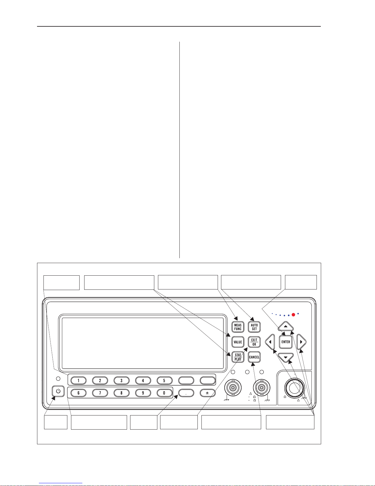
Getting Familiar with
the Counter
The front panel is laid out in a logical fashion.
Take a few seconds to find the sections described below on the front panel of your counter. See also the figure on this page. It will
help you locate the different keys faster.
Operating the Counter
3-2 Introduction
TRIG
GATE
TRIG
pendulum
TIMER / COUNTER / ANALYZE R
100ps / 300MHz
CNT-90
INPUTINPUT
INPUT A
SETTINGSETTING
SETTINGS
MATH/LIM USER OPUSER OP
USER OPT
HOLD / RU
HOLD / RUN
RESTARTINPUTINPUT
INPUT B
A
300 MHz
B
MAX
12Vrms 50
30Vrms 1M
!
C
MAX +30dBm
50
0.2 8GHz
!
Move CursorSave&Exit Don't Save&ExitPower
Hard Menu Keys
Freeze
Select Function Autoset/Preset Enter
Presentation Modes
Soft Keys

Description of Keys
Power
The ON/OFF key is a toggling secondary
power switch. Part of the instrument is always
on as soon as line power is applied, and this
so-called standby condition is indicated by a
red LED above the key.
Select Function
This hard key is marked MEAS FUNC.
When you depress it, the menu below will
open.
The current selection is indicated by text inversion. Select the measurement function you
want by depressing the corresponding soft key
right below the display. A new menu will appear where the contents depend on the function. If you for instance have selected Fre
-
quency, you can then select between Fre
-
quency, Frequency Ratio and Fre
-
quency Burst. Finally you can also change
the preselected input channel.
Autoset/Preset
By depressing the AUTOSET key once after
selecting the wanted measurement function
and input channel, you will most probably get
a measurement result. The AUTOSET system
ensures that the trigger levels are set optimally
for each combination of measurement func
tion and input signal amplitude, provided that
you apply relatively normal signals.
By depressing the AUTOSET key twice
within two seconds, you will enter the Preset
mode, which takes you another step further to
wards fully automatic settings for your current
measurement. Such auxiliary functions as
measuring time, mathematics, filter and arm
-
ing are then reset to their default values. The
intention is to prevent possible lockups and
misinterpretations when changing measure
-
ment function or test setup, for instance.
Move Cursor
There are four cursor keys for moving the cur
sor, normally marked by text inversion,
around the menu trees.
Enter
When you want to confirm a choice without
leaving your menu position, press this key.
Exit/OK
This hard key performs the Save & Exit operation. You will confirm your selections by depressing the key, and at the same time you
will exit the current level and enter the next
higher level in the menu tree.
Cancel
This hard key performs the Don't Save & Exit
operation. You will exit the current level by
depressing the key and enter the next higher
level in the menu tree without confirming any
selections made.
Description of Keys 3-3
Operating the Counter

Presentation Modes
n
VALUE
The Value Mode gives the result of the main
measurement function as a numerical value in
large characters with full resolution. In addi
-
tion, the results of supplementary measure
ments are displayed in smaller characters with
limited resolution near the bottom of the
screen.
In case the Limits Alarm function is enabled,
Range is the selected Limit Mode,andAlarm
is the selected Limit Behavior,thenasimple
graph is also given in which the result of the
current measurement is shown as an
'emoticon' at a position relative to the limits
set by the operator. Values are represented by
a smiling face when inside the limits and a
frowning face when outside.
If one of the limits has been exceeded, the
limit indicator at the top of the display will be
flashing. Only data inside the limits is used for
autoscaling, so results outside the visible
graph area are replaced by an arrowhead at the
left or the right edge of the display.
n
STAT/PLOT
If you want to analyze a number of successive
measurements using statistical methods, this is
the key to operate. There are three display
modes available by toggling this key:
•
Numerical Mode
•
Histogram Mode
•
Trend Plot Mode
Numerical Mode
In this mode the statistical information is dis
-
played as numerical data containing the fol
-
lowing elements:
•
Mean: running mean value of the main
measurement over N samples
•
Max: maximum value
•
Min: minimum value
•
P-P: peak-to-peak deviation
• Adev: Allan deviation
•
Std: standard deviation
Histogram Mode
Successive measurement results are converted
into a histogram.
The number of bins along the horizontal axis
can be set by the user through the Settings
® Stat menu. The bins in the histogram are
autoscaled based on the measured data. Lim
-
its, if enabled, and the running mean value
X
are shown as vertical dotted lines. The center
of the graph is indicated by a filled triangle on
the X-axis. The corresponding numerical
value is displayed below it and so is the scale
Operating the Counter
3-4 Description of Keys

factor. Enabled limits affect the autoscaling so
as to visualize the current measurements and
the set limits simultaneously.
Trend Plot Mode
This mode is used for observing periodic fluc
-
tuations or possible trends.
A trend plot terminates (if HOLD is activated)
or restarts (if RUN is activated) after the set
number of samples has been completed. The
trend plot is always autoscaled based on the
measured data, starting with 0 at restart. Limits are shown as horizontal lines, if enabled.
n
Remote
When the instrument is controlled from the
GPIB bus, and the remote line is asserted, or
when the instrument is controlled from the
USB bus, then the presentation mode changes
to Remote, indicated by the label REM on
the display. The main measurement result and
the input settings are displayed in this mode.
Hard Menu Keys
These keys are mainly used for opening fixed
menus, from which further selections can be
made, for instance by means of the soft keys.
n
Input A
By depressing this key, the bottom part of the
display will show the settings for Input A.
The active settings are in bold characters and
can be changed by pressing the corresponding
soft key below the display. You can also move
the cursor, indicated by text inversion, with
the RIGHT and the LEFT arrow keys to the
desired position and then make the selection
by pressing the UP or the DOWN arrow keys.
You can also use the ENTER key.
The selections that can be made in this menu
are:
•
Trigger Slope: positive or negative, indi
-
cated by corresponding symbols
•
Coupling: AC or DC
•
Impedance: 50 W or1MW
•
Attenuation: 1x or 10x
•
Trigger: Manual or Auto (always Auto
10/90 % when measuring transition
times).
•
Trigger Level: If Manual has been selected, the absolute level can be adjusted with the up/down arrow keys or
by entering a numerical value from the
keyboard.
•
Filter: On or Off. Pressing ENTER or the
soft key below the text opens up the Fil
-
ter Settings menu. See below.
You can select a fixed 100 kHz analog
filter or an adjustable digital filter. The
equivalent cutoff frequency is set via the
value input menu that opens if you se
lect Digital LP Frequency from the menu
above.
n
Input B
The available settings under Input B are
equal to those available under Input A.
Description of Keys 3-5
Operating the Counter

n
Settings
This key accesses a range of more sophisti
cated instrument settings that usually need not
be changed for basic measurements. The fig
-
ure below shows the display after recalling the
default settings via the USER OPT menu.
A detailed description of all the possibilities is
far beyond the scope of this introductory man
ual. See the User's Manual for full details on
functions mentioned and unmentioned here.
Meas Time
This value input menu is only useful if you select a frequency function. Longer measuring
time means fewer measurements per second
but gives higher resolution. You can change
the Measuring Time by entering a numerical
value, or you can use the UP/DOWN arrow
keys to increase or decrease the current value.
Burst
This settings menu facilitates measurements
on pulse-modulated signals and is only useful
if Frequency Burst is the main measurement
function.
Both the carrier frequency and the modulating
frequency – also known as the pulse repetition
frequency (PRF) – can be measured, often
without the support of an external arming sig
-
nal (see below).
Arm
Arming is the general term used for the means
to control the actual start or stop of a measure
ment. When arming is used, the normal
free-running mode is inhibited, and triggering
takes place only when certain pretrigger con
-
ditions are fulfilled.
The signal(s) used for initiating the arming
can be applied to three channels, and the start
channel can be different from the stop chan
nel. All conditions can be set via the menu
below.
Trigger Hold-Off
In this menu you can set the delay during
which the stop trigger conditions are ignored
after the measurement start. A typical use is to
clean up signals generated by bouncing relay
contacts.
Statistics
In this menu you can find the following
submenus:
•
No. of Samples: Set the number of sam
-
ples used for calculation of various sta
-
tistical measures.
•
No. of Bins: Set the number of bins
used in the histogram mode.
•
Pacing: Set the delay between succes
sive measurements, called Pacing
Time, to ON or OFF.
Operating the Counter
3-6 Description of Keys

•
Pacing Time: Set the pacing time to a
value between 2 ms – 1000 s.
Timebase Reference
Here you can select if the counter is to use the
internal or an external timebase reference. If
Auto is selected, an external timebase will be
used only if it is interpreted as a valid signal,
i.e. both amplitude and frequency must be
within specified limits. This does not imply,
however, that an external reference source has
to be better in any sense than the internal
timebase oscillator. The EXT REF indicator
at the upper right corner of the display shows
that the instrument is using an external
timebase reference.
Miscellaneous
The options in this menu are:
•
Smart Time Interval: When selected, the
counter decides by means of
timestamping which measurement
channel is leading.
•
Auto Trig LF: In a value input menu you
can set the lower frequency limit for au
-
tomatic triggering and voltage measure
ments in the range 1 Hz – 100 kHz. A
higher limit means faster settling time
and consequently faster measurements.
•
Timeout
Switch the Timeout function ON or OFF.
In case the input signal gets interrupted,
the timeout system (if enabled) will hold
the last measurement result on screen
only during the selected period of time
(see next paragraph). Then the screen
will be blanked, and a pending bus
query will read a zero result. In case
timeout is switched off when the signal
gets interrupted, the display will freeze,
i.e. the result of the last complete mea
surement will stay on screen indefinitely.
A pending bus query will also wait indef
initely for a response, unless the test
system controller has enabled its own
timeout.
•
Timeout Time
Set the maximum time the instrument
will wait for a pending measurement to
finish before outputting a zero result.
The range is 10 ms to 1000 s.
n
Math/Limit
Here you will find the menus for mathematical postprocessing of the measurement result
and for setting up the limit testing function.
Math
You can modify the measurement result math
-
ematically by scaling or offsetting before pre
sentation on the display. This feature can be
used for getting revolutions/min instead of Hz
or for recalculating the frequency in case a de
-
vice causing frequency conversion (e.g. a
Description of Keys 3-7
Operating the Counter

multiplier or a mixer) is part of the system un
-
der test.
Select one of four formulas and enter the con
stants K, L and M to make the counter show
directly what you want, without tedious recal
culations. X stands for the current unmodified
measurement result. See the User's Manual for
a closer description.
Limits
This menu is used for setting numerical limits
and selecting the way the instrument will report the measurement results in relation to
them. See the section Presentation Modes on
page 3-4 for a short description or the User's
Manual for a more detailed description.
n
User Options
From this menu you can reach a number of
functions that are not directly involved in the
measurement process.
Save/Recall Menu
Twenty complete front panel setups can be
stored in non-volatile memory; the first ten of
them can be user-protected. The different set
-
ups can be individually labeled to make it eas
-
ier for the operator to remember the applica
-
tion.
The following can be done:
•
Save Current Setup: Select one of
twenty positions.
•
Recall Setup: Here you will find a factory-programmed default setup as well
as any setups you may have stored before.
• Modify Labels: The seven soft keys right
below the display plus the numeric input
keys 6, 7, 8, 9, 0 are used for entering
lower-case letters and digits much in the
same way as you write SMS messages
on a cell phone. Each label can hold
seven characters.
•
Setup Protect: ON or OFF. Only setup
positions 1-10 can be protected against
inadvertent overwriting.
Calibration Menu
This counter has an extensive system for
closed-case calibration by software. Refer to
the Service Manual for details.
Operating the Counter
3-8 Description of Keys

Interface Menu
Set the active interface to GPIB or USB and
enter the GPIB address.
•
Bus Type: Choose GPIB or USB
•
GPIB Mode: There are two alternative
command systems, Native and Compat
-
ible. See the User's Manual and the
Programmer's Handbook for details.
•
GPIB Address: Enter the bus address,
an integer between 0 and 31. The fac
-
tory default value is 10.
Test Menu
Different parts of the hardware can be tested
by means of built-in software support.
Test Mode
You can select among the following test
modes:
•
All (The five individual tests below are
performed in sequence)
•
Memory (RAM) test
•
Memory (ROM) test
•
Logic hardware test
•
LCD & display drivers test
•
Interface test
Start Test
Press this key to run the selected test.
About (Information)
Read status information about the instrument.
•
Model
•
Serial number
•
Firmware version
•
Factory-installed options
•
Calibration date
n
Hold/Run
This key serves the purpose of manual arm
ing. A pending measurement will be finished
and the result will remain on the display until
a new measurement is triggered by pressing
the RESTART key. The HOLD sign in the
upper right corner of the screen indicates that
no new measurements are taking place.
Pressing the key again will resume the contin
-
uous measurement mode.
n
Restart
Often this key is operated in conjunction with
the HOLD/RUN key (see above), but it can
also be used in free-running mode, especially
when long measuring times are being used, to
initiate a new measurement after a change in
the input signal. RESTART will not affect
any front panel settings.
Entering Numeric Values
Sometimes you may want to enter constants
and limits in a value input menu, for instance
after you have pressed the MATH/LIMIT key.
You may also want to select a value that is not
in the list of fixed values available by pressing
the UP/DOWN arrow keys. One example is
Meas T ime under SETTINGS.
Whenever it is possible to enter numeric values, the keys marked with digits (0,1,...9),
decimal point (.)andchange sign (±)takeon
this alternative numeric meaning.
It is often convenient to enter numbers using
the scientific format with mantissa and
exponent. When this is supported in a particu
lar menu, the rightmost soft key will be
marked EE (stands for Enter Exponent), mak
ing it easy to switch between the mantissa and
the exponent.
Press EXIT/OK to store the new value or
CANCEL to keep the old one.
Description of Keys 3-9
Operating the Counter

This page is intentionally left blank.
Operating the Counter
3-10 Description of Keys

Chapter 4
Ex ercises

Preparation
For these exercises you will need a '9X' coun
ter, a function generator and two BNC cables
of approximately equal length. Set up the gen
erator according to the following table, and
connect the main output of the generator to in
-
put A of the counter.
Basic Startup
Since the counter will remember its previous
setting in nonvolatile memory, it is recom
-
mended that you recall the factory default set
-
ting before you begin.
To do so, first key in the following sequence:
USER OPT ® Save/Recall ®
® Recall Setup ® Default.Thenpress
the AUTOSET key twice within two seconds.
The preselected measurement function will be
Frequency, and the trigger levels will be au
tomatically adjusted in relation to the applied
signal.
If a signal with a frequency of 20 Hz or higher
and an amplitude large enough to trigger the
counter is connected to input A, its frequency
will now be displayed.
High-Resolution
Frequency
Measurement
Note the high resolution of the primary
readout. Twelve digits are displayed in a mea
-
suring time of 1 s. Don’t worry about the trig
ger settings, the AUTO trigger will take care
of any input signal above 20 Hz. This fre
quency limit can, if so desired, be changed
down to 1 Hz or up to 100 kHz with a tradeoff
between frequency and measurement speed. If
the generator has been set up properly, you
will now read the frequency (1 MHz) on the
display.
Built-In Math
Processing
With the built-in math functions, you can
make post-processing operations like scaling
and offsetting an easy benchtop task without
having to hook up a computer to the instru
-
ment. You can, for example, display any devi
ation from the desired value instead of directly
showing the result of the measurement itself.
This is known as offsetting.
In the following, the direct, unscaled result of
the counter's measurement process will be re
-
ferred to as 'X'.
Exercises
4-2 Preparation
Set up the generator: Function: Square
Wave
Frequency: 1 MHz
Amplitude: 5 V
pp
Modulation: Off
TRIG
GATE
TRIG
pendulum
TIMER / COUNTER/ ANALYZE R
100ps / 300MHz
CNT-90
INPUTINPUT
INPUTA
SETTINGSETTING
SETTINGS
MATH/ LIM USER OPUSER OP
USEROPT
HOLD/ RU
HOLD/ RUN
RESTARTINPUTINPUT
INPUTB
A
300MHz
B
MAX
12Vrms 50
30Vrms 1M
!
C
MAX+30dBm
50
0.2 8GHz
!
Autoset
5V
pp
1 MHz
TRIG
GATE
TRIG
pendulum
TIMER / COUNTER/ ANALYZE R
100ps / 300MHz
CNT-90
INPUTINPUT
INPUTA
SETTINGSETTING
SETTINGS
MATH/ LIM USER OPUSER OP
USEROPT
HOLD/ RU
HOLD/ RUN
RESTARTINPUTINPUT
INPUTB
A
300MHz
B
MAX
12Vrms 50
30Vrms 1M
!
C
MAX+30dBm
50
0.2 8GHz
!
Math/Limit

To set up the counter to display any deviation
from 1 MHz, press the MATH/LIM key and
select Math. The display will show that Math
is still Off. Press the soft key below the Math
Off indicator to enter the Formula Select
menu. Use the cursor keys to mark the for
-
mula K*X/M + L and confirm by pressing the
EXIT/OK key.
Now enter the numerical values for the con
-
stants K, L and M. The default values are:
K=1, L=0 and M=1. In this case only L has to
bealteredto-1*10
6
in order to get the job
done.
Open the value input menu for L by pressing
the soft key below the menu heading marked
L on the display. Press 1 followed by ±, EE
(short for Enter Exponent) and 6. Confirm and
exit by pressing EXIT/OK.PressEXIT/OK
repeatedly until the display is showing the
measurement result, now modified to reflect
any deviation from 1 MHz.
Change the generator frequency upward and
downward just a little, and watch the counter's
display.
High-Speed
Measurements
The benefits of high speed measurements for
benchtop use become obvious when you use
statistics. For instance, the '9X' can make
1000 7-digit measurements and present the
standard deviation (jitter) in less than one sec
-
ond.
Recall the default setting and press
AUTOSET twice within two seconds before
tweaking the controls to reach the optimum
measurement speed for your application. See
the following two paragraphs.
Under the INPUT Menus:
Auto trigger level settings in this model is so
fast that you will normally not notice any dif
ference in speed if auto is on or off. However,
if you use statistics to make hundreds or thou
-
sands of measurements, the fractions of a sec
ond it takes to calculate trigger levels before
each measurement add up to a considerable
time over the total sequence.
The measuring speed can be increased sub
stantially if you set the trigger levels manually
once, before a lengthy measurement sequence
starts.
Press INPUT A and choose MAN for the
MAN/AUTO setting. Now press Trig to open
the trigger level value input menu. Enter a
level of +0.5 V. Confirm the selection by
pressing EXIT/OK twice.
Under the SETTINGS Menu:
By making the measuring time for each
sample as short as possible you can also increase the overall measuring speed. Remember, however, that there is always a tradeoff
between measuring time and resolution.
Press SETTINGS and then MeasTime.Use
the DOWN arrow key to set the measuring
time to the minimum value. Confirm by press
-
ing EXIT/OK twice.
Now the counter is taking measurements at a
very high speed.
Toggle the STAT/PLOT key to see the statis
tical measures and the graphical presentation
of the result.
The measuring speed can be increased even
more, if you take advantage of the features
that are available over the GPIB. These in
clude commands for turning off the display
update, etc. In this way you can reach speeds
High-Speed Measurements 4-3
Exercises

up to 2000 transferred measurements/s, each
individually triggered. If you save the results
to the internal memory of the instrument for
later transfer, you can even attain an impres
-
sive speed of 250,000 measurements/s.
Time Measurements
So far we have only been using the frequency
function. Now we will use some others.
To measure the period of the signal, simply
press the key MEAS FUNC followed by PE
-
RIOD. Select SINGLE or AVERAGE de
-
pending on the desired resolution and measur
-
ing speed. Finish by selecting the input chan
-
nel.
To measure pulse width, use the keys MEAS
FUNC and PULSE followed by POS or
NEG depending on whether you want to mea-
sure the positive or the negative pulse width.
Finish by selecting the input channel.
Jitter Measurements
(Statistics)
You can make statistical measurements, such
as pulse width jitter, directly via the front
panel of the counter.
Make sure the counter is measuring positive
pulse width on input A. To turn on statistics,
press the STAT/PLOT key. Change the dis
play mode by toggling the same key. Return
to the numerical mode and watch the results.
The display gives you a survey of several sta
tistical measures. See also page 3-4. The rms
jitter is equivalent to the standard deviation of
100 measurements, where 100 is the default
value for the sample size.
If you want to change the default values for
sample size, bin size or pacing time, then you
can press the SETTINGS menu key and after
that the STAT soft key.
Other
Single-Channel
Measurements
The counter/timer can help you characterize
signals even further. Recall the default settings
and press AUTOSET twice.
Duty Cycle
Use the MEAS FUNC key to select Duty and
then Positive A (for positive-pulse duty cycle measurement on channel A). Change the
frequency of the generator to 10 kHz. Then
vary the symmetry (duty cycle) of the square
wave on your generator. The counter’s display
will directly show the duty cycle as a number
between 0 and 1. There is no need to manually
calculate duty cycle by dividing pulse width
by period.
The duty cycle (D) is defined as:
D=W/T
D = 0.5 for a square wave.
Exercises
4-4 Time Measurements
W
1
W
2
T
LOW
DUTY CYCLE
HIGH
DUTY CYCLE

Rise Time
Use the MEAS FUNC key to select Time,
Rise Time and A (for channel A). Press IN
-
PUT A and make sure the following settings
are active:
•
Coupling DC
•
Impedance 50 W.
•
Attenuation 1x
Notice the rise time for a square wave, which
is measured totally automatically.
Now change the generator output to a
triangular waveform. See next figure.
Vary the rise time and notice the difference on
the display.
Fall Time
Fall time is measured in a similar way by se
-
lecting Fall Time instead of Rise Time
above.
Remarks
Varying the symmetry of the waveform will
also vary the rise and fall times.
As you have noticed, there is no need to check
max and min voltages and calculate 10 % and
90 % levels. The counter does it all automati
-
cally.
Volt Max/Min Measurements
The counter can also measure the peak voltage
values of your input signal. Use the MEAS
FUNC key to select Volt. Then select Vpp,
Max or Min as the primary function. The re
sults of the secondary functions are calculated
simultaneously and displayed in a smaller
font.
Set up the
Generator:
Frequency: 200 Hz
Waveform: Square
Symmetry: 50%
Amplitude: 2-5 V
Note that the voltage reading on the counter
may be lower than the setting indicated on the
generator, as some generators indicate the
open output voltage, while the counter is now
set to 50 W input impedance.
Channel Swapping
There is no separate key or function for swapping input channels, as found on some other
counters, yet by exploring the menu trees under MEAS FUNC you will find that all mea
surement functions can be performed on each
of the two input channels, thus eliminating the
need for a swap function.
As both input channels have the same specifi
-
cation, the definition of primary and second
-
ary channel (as seen with some other coun
-
ters) is not relevant with the '9X' from a tech
nical point of view.
Other Single-Channel Measurements 4-5
Exercises
'
'

Two-Channel
Measurements
The counter can measure the timing relationship
between two channels with the Time Interval
AtoBand Phase A rel B functions.
Time Interval
Often function generators have a TTL output in
addition to the main output. We will make use of
this now. Connect a BNC cable from the TTL
output to Input A on the counter and another
BNC cable from the main output on the function
generator to Input B.
Set up the counter: Trigger Level:
AUTO
Function:
TIME INT A-B
Coupling: DC
(both A and B)
You can now read the time difference between
the TTL and main outputs of the generator.
Phase
So far the counter has shown the timing rela
tionship between the TTL and the main output
of the generator as a time delay. You can also
show this as phase shift between the signals.
n
Using Auto to set fixed trigger
levels (Auto Once)
Some measurements like Phase A rel B ben
efit from having fixed trigger levels. This is
because a change in trigger level causes a
change in the measured phase shift, and Auto
might change the trigger level between mea
-
surements.
To avoid calculating the trigger levels yourself,
you can let the counter measure the Auto levels
and then store them as fixed values.
Press INPUT A and check that Auto is still se
-
lected. Read the Auto trigger level for Input
A. Select Man. Note that the automatically
calculated trigger level is now entered as a
fixed manual level.
Press INPUT B and run through the same
steps once more to store this level as a manu
-
ally set trigger level as well.
n
Procedure
Use the MEAS FUNC key to select Phase A
rel B. Now the channel delay is expressed as
phase shift in degrees.
Increase the frequency of the generator to
2 kHz, 20 kHz, 200 kHz, 2 MHz, and
20 MHz. Watch the phase difference change.
Memory Settings
See also page 3-8.
The counter has 20 memory locations in
which you can store frequently used instru
-
ment settings.
–
To save an instrument setting, press the
USER OPT key.
–
Select the Save/Recall key.
–
Press Save Current Setup, and select
one of the memory locations using the
LEFT/RIGHT arrow keys. Note that the
first ten positions may be user-protected.
–
Press EXIT/OK three times to return to the
normal display mode.
–
Now change some settings on the counter,
and repeat the first steps above, until you
have pressed Save/Recall.
Exercises
4-6 Two-Channel Measurements

–
Press Recall Setup and select the mem
ory location in which you stored your
original setup.
–
Press EXIT/OK three times to return to the
normal display mode.
–
Watch the counter restore your original
settings.
The memory is nonvolatile, so it will not
change if you switch off the counter, nor if
you restore the default setup. All settings are
stored including trigger levels, mathematical
constants etc. You can even attach a label to
each stored setup, which helps you identify
the application easier.
Auxiliary Functions
There is a collection of useful, however seldom used auxiliary functions. Only one will
be mentioned here. See the User's Manual for
a more comprehensive description. Before we
go on, first recall the default setup and then
press AUTOSET twice.
Time-Out
Check that the counter is measuring. Discon
nect the Input A signal, and the measurement
result will freeze on the display. Connect the
signal again and the counter resumes
measuring immediately.
Is this a feature? Well, yes and no. Yes, since
this function gives touch-hold characteristics.
No, since interrupted measurements giving
false readouts may be misinterpreted by auto
-
matic test equipment and can even cause con
trol SW to halt. The solution to this problem is
the time-out function.
–
Press the SETTINGS key and then Misc
® Timeout Time.
–
Calculate the time needed to decide if
there is a signal present at the input.
–
Enter this time using the numerical soft
keys, for instance 1 s.
–
Activate the time-out function by toggling
the soft key Timeout to ON.
–
Disconnect the signal and check that the
counter shows '---' after one second.
Keep in mind that the value you select for this
time-out must always be longer than the
selected measuring time.
Summary
This concludes the Getting Started Manual.
Now you have been familiarized with the control structure and the display modes of the
model '9X'.
There are still a great many features to discover, so have a look at the User's Manual and
the Programmer's Handbook, which can be
found on the CD-ROM. Continue to explore
the vast realm of measurement possibilities
that opens up to the user of this instrument.
Auxiliary Functions 4-7
Exercises

V
service@pendulum.se
www.pendulum.se
Altaria Services Sp. z.o.o.
 Loading...