

K.D. Defiant II Locker
Assembly Instructions
Updated
9/06
PN 86179
K.D. DEFIANT II LOCKER
ASSEMBLY INSTRUCTIONS
These Instructions Cover GUARDIAN DEFIANT AND
INVINCIBLE II DEFIANT SINGLE POINT LATCH LOCKERS
CONTENTS
General Instructions 1
Major Locker Components 2
Hardware and Small Locker Parts 3
Basic Defiant Assembly Instructions (Single Row Lockers) 4-5
Guidelines for Rear Leg Spacing 4
Hook and Coat Rod Guidelines 5
Individual Closed Bases 6
Zee Base 6
Unit Slope Tops, Slope Top Kits, Continous Slope Hoods 7
Invincible II Group End Kits 8
Double Row Invincible II Lockers 8
GENERAL INSTRUCTIONS
1. These instructions are for the person who will actually perform or supervise the assembly of the lockers.
2. Check material received against the packing list. First check the number of packages received and then check
the contents of each package.
3. Check material received for damage. If any of it is damaged, secure a “damage notation” from the carrier.
4. Identify each part as it is unpacked and put like parts together as close as possible to the working area in which
they are to be assembled.
5. Be careful to use the correct hardware as specified in the assembly instructions.
CAUTION
It is the responsibility of the persons assembling the lockers to properly install all components and hardware as specified in
these instructions and any accompanying drawings for specific installation.
· INSTALL ALL UNITS PLUMB AND LEVEL
· TIGHTEN ALL HARDWARE SECURELY
PENCO PRODUCTS, INC. 99 Brower Ave., PO Box 378,
Oaks, PA 19456-0378 · 800-562-1000 · Fax 610-666-7561
double row lockers must be floor anchored and if possible wall or ceiling anchored.
Single row lockers must be floor and wall anchored,
www.pencoproducts.com
1
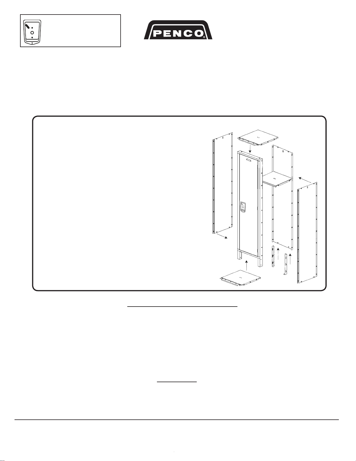
MAJOR LOCKER COMPONENTS For 1,2,3,4,5,6 TIER AND MULTI-TIER DOORS
18
o
DIVISIONS
FLAT & SLOPED
FLAT & SLOPED
Flat Top Locker
Body Parts
Slope Top Locker
Body Parts
Flat
Top Divisions
Divisions for flat
top locker are
the same for left
and right
(just turn panel
180 degrees).
Bottom of divisons and back panels have the first hole on flange 1-3/4” from edge, (top of divisons and back panel have the first hole 1-1/4” from edge).
Illustration of Number Plate, Lock Hole Cover Plate or
Built -in Locks Positioning
Defiant II Locker
(Single Point Latch)
Number
Plate
Flat
Top
Back
Panel
Top and
bottom
flanges
are 90°
Slope Top
Divisions
Slope
Top
Back
Divisions for sloped tops
are left and right specific.
The top of the division is
cut at a 18° angle.
Panel
Top of the
flange is cut
at an
18°angle.
Locker Tops, Bottom (T.A.B.) and Shelves
Flat Top (T.A.B.)
Shelf
or Slope Top
Flat Top
(T.A.B.)
Defiant II Single
Point Latch
See page 5 for
more details on
Deant II Lockers
Anti-Pry / Lock
Alignment
Bracket with
Cover Plate
or
Built-in Lock
with
Anti-Pry / Lock
Alignment
Bracket
1 Tier
2 Top and Bottom T.A.B.)
1 Intermediate Shelf
Flat Top Slope Top
Flat Tops (same part
Bottom
(T.A.B.)
2 Tier
3 Top and Bottom (T.A.B.)
as bottoms)
Note: Shelf front has
a return flange
Slope Top
Shelf
Top and Bottoms are
often called a T.A.B.
(top and bottom)
Bottom
(Same part
as flat top)
3 Tier
4 Top and Bottom (T.A.B.)
Single row lockers must be floor and wall anchored,
double row lockers must be floor anchored and if possible wall or ceiling anchored.
2
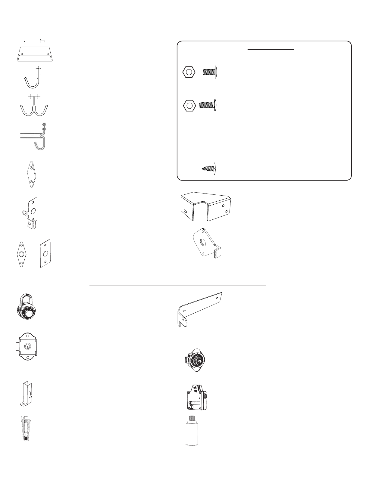
HARDWARE AND SMALL LOCKER PARTS
1
PENCO PRODUCTS INC.
www.pencoproducts.com
Not all parts come with all lockers. Check packing list for what parts are to be used with what models of lockers.
or
Number Plate and Rivet
To be riveted to top of locker door.
Single Prong Wall Hook
To be bolted to divisions and to back panel.
Single & Double Prong Ceiling Hook
To be bolted to bottom of shelf or top of locker.
Coat Rod Hooks with Rod
Hooks to be bolted to divisions with coat
rod in between, used in single tier, Duplex,
2,7,8 person and Dual lockers 18” or more in
depth.
Hook Clip
Used to attach single prong wall hooks and
coat rod hooks in lockers with Diamond
Perforated divisions at ends only.
Door Pull
Used on box locker door unless a built-in
lock is used. To be mounted on inside of
door with pull tab inserted through vertical
slot in door.
Lock Hole Cover Plate
Used to cover hole in door when built-in locks
are not used. To be mounted on inside of
door.
Nuts and Bolts
10—24 x 3/8” Truss fin head bolt and nut for assembly of
locker body parts. Tighten nut with a wrench or
nut driver. (bolt is tamper resistant so it has no
slot for a screw driver)
10—24 x ½” Truss fin head bolt and nut for assembly of
the entire Invinicible II locker. In the
Vanguard and Guardian lockers this nut and
bolt is used in joining locker groups, locker
legs and 2 hooks with the partition betweeen
the hooks. Tighten nut with a wrench or nut
driver (bolt is tamper resistant so it has no
slot for a screw driver)
NO. 8 x 3/8 “ Sheet metal screw for slope tops only.
Bracket Support (Defiant II)
Strengthens locking point on Defiant II lockers.
Bolts to Defiant II hasp and to side of locker.
Anti-Pry / Lock Alignment Bracket
(Defiant II) Used on back of recessed pocket
in Defiant II Lockers (Single Point Latch).
Optional Items That are Ordered Separately from Locker
Combination Padlock (9/32” or .281” Shackle)
Used to secure locker door when built in lock is not
used. Lock may come from another supplier other
than Penco Products.
Built-in Key Lock
Used to secure locker door when padlock is not
used. This lock replaces Lock Hole Cover Plate or
Door Pull. To be mounted on inside of door. Lock
may come from another supplier other than Penco
Products.
Locker Shoe
Can be used on the front legs of locker to secure to
floor. Protects floor along with leveling lockers on an
uneven floor.
Concrete Floor Anchor
1/4 x 2” Used to secure locker to a concrete floor.
Bolt type will vary with floor type.
Single row lockers must be floor and wall anchored,
double row lockers must be floor anchored and if possible wall or ceiling anchored.
Side Stiffener
(Defiant II Guardian Doors Only)
When built-in locks are used on Defiant II Guardian Lockers (24 gauge side panels), the last locker in
a row of lockers, is to have a Side Stiffener bolted to
the Defiant II lock hasp and side of locker (replaces
Bracket Support if built-in lock are used).
Built-in Combination Lock
Used to secure locker door when padlock is not used.
This lock replaces Lock Hole Cover Plate or Door
Pull. To be mounted on inside of door. Lock may come
from another supplier other than Penco Products.
Safe-O-Mat Coin Operated Lock
Used to secure locker door when padlock is not used.
This lock replaces Lock Hole Cover Plate. Lock engages when token or coin is deposited.
Touch Up Paint
Used to touch up paint finish (21 standard colors).
3

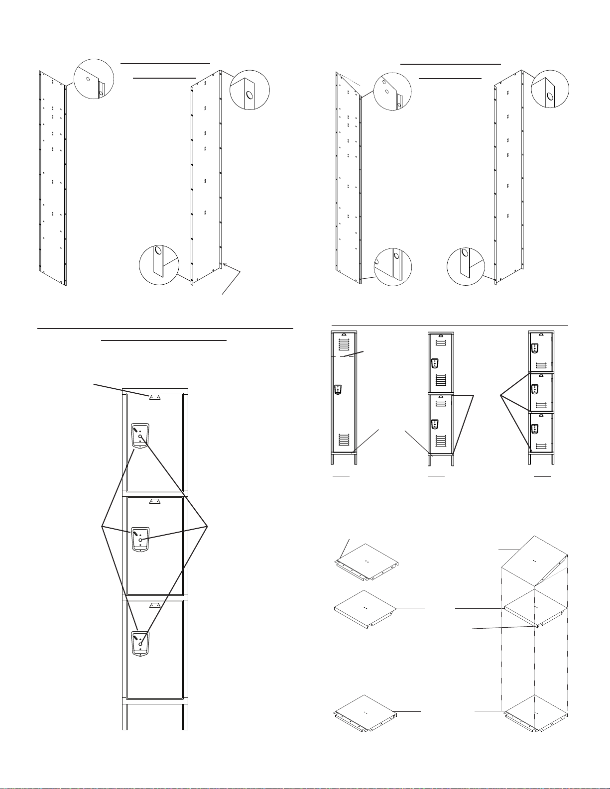
DefiAnT LockeR ASSeMBLY inSTRUcTionS
START
Place Locker Back on a at surface or
1
saw horses and Bolt Top and Bottom
5
(TAB) to inside of Back
Top and Bottom (TAB)
Back
FOR SINGLE
LOCKER
3
Bolt Shelf
to Side
Panel
and Back
Side
Panel
FOR SINGLE TIER
Bolt Division (Side Panel) to inside of
2
Back and outside of Top (TAB)
Shelf
Adj. Leg
4
If legs are supplied, bolt Adjustable Leg inside of Side Panel (leg height can be adjusted to
level and anchor locker)
FOR ROW OF
LOCKERS
Back
Top and
Bottom
(TAB)
Side
Panel
6
FOR 2 TIER
Bolt Division (Side Panel) to inside of
2
Back and outside of Top (TAB)
Adj. Leg
4
FOR 2 TIER
Bolt Top
and Bottom
(TAB) to Side Panel
and Back (repeat
step if 3 Tier)
Top and
Bottom
(TAB)
Back
3
Side
Panel
FOR 3 TIER
FOR 3 TIER
2
Back
Adj. Leg
4
FOR SINGLE TIER
If Coat Rod
is supplied
(Single tier
lockers only)
Before bolting
TAB and Shelf to
division, install
coat rod hooks
on the inside of
divisions. Spread
apart division and
then insert coat
rod into coat rod
holder on coat rod
hook.
FOR SINGLE
LOCKER
Bolt Bottom (TAB) to
inside of Back and
then bolt Divisions to
Back, TAB, and shelf
or shelves if provided.
ReAR Leg SpAcing foR SingLe Row LockeRS
IMPORTANT: If lockers have been ordered with grouping specied, assemble lockers
as ordered. Back legs should not exceed 45” distance between legs. If grouping has
not been specied assemble lockers using the chart.
Width of Single Locker (inches) 7-1/2” 9” 12” 15” 18” 24”
Lockers in a Single Row Grouping 9 8 7 6 4 3
Back Legs in Each Grouping 9 6 5 4 3 2
FOR ROW OF
LOCKERS
Bolt Bottom (TAB) to inside of Back and Divisions.
Then bolt through Back, Division and the next locker’s
back. If legs are supplied, see Rear Leg Spacing for
Single Row Lockers below. Then repeat steps 1 to
5. Due to size and bulk, it is best to build lockers in
groups of no more than 3 wide before putting doors on
and then putting them in place.
Back
Locker Frames show with legs
Place Locker Door and Frame over edges of Divisions (Side
Panels), and edges of Top and Bottom (TAB). Open Door and
bolt Door Frame to Divisions, Top and Bottoms (TABS). If needed, loosen bolts on Legs to level locker and then re-tighten.
Joining LockeR gRoUpingS
Top View of Two Groupings of Three Lockers
First
Locker
Group
Second
Locker
Group
FOR SAFETY PURPOSES WE STRONGLY RECOMMEND THAT ALL LOCKERS BE EITHER FLOOR OR WALL ANCHORED
Single row lockers must be floor and wall anchored,
double row lockers must be floor anchored and if possible wall or ceiling anchored.
4

COMBINATION
LOCK
STAINLESS
STEEL
DEFIANT II
RECESSED
HANDLE
ANTI-PRY / LOCK ALIGNMENT
BRACKET
UNIT
COMBINATION LOCK
Table of Locker Coat Hook and Rod Quantities
Number of Pieces Supplied per Locker FRAME * - Standard Construction Only
1 Tier
2
Tier
3 Tier
4,5,6,8,9
Tier
2 Person 7 Person 8 Person
16
Person
Duplex Dual
Single Prong Hooks
Depth Less than 18" AND:
. . . Width less than 15"
3 6 9 - n/a n/a n/a n/a n/a 4
. . . Width =15" or more
4 8 12 - 4 n/a n/a n/a 4 4
Depth 18" or more AND:
. . . Width less than 15"
1 6 12 - n/a - - n/a n/a -
. . . Width =15" or more
2 8 12 - - - - n/a - -
Double Prong Hooks
Depth 18" or more - - - - - - - - - -
Depth LESS than 18" AND:
. . . Width is LESS than 21"
1 ** 2 - - - n/a n/a n/a - -
. . . Width is 21" or more
2 4 - - n/a n/a n/a n/a n/a -
Coat Rod Hooks
Depth Less than 18"
- - - - - n/a n/a n/a - -
Depth 18" or more
2 - - - 4 2 4 - 4 4
Coat Rods
Depth Less than 18"
- - - - - n/a n/a n/a - -
Depth 18" or more
1 - - - 2 1 2 1 2 2
n/a: Not Applicable in Standard Construction
* Exceptions: 7, 8 & 16 Person quantities are for entire unit.
** Exception: Single Tier 9" wide x 15" deep has N0 Double Prong Hooks
DefiAnT LockeR ASSeMBLY inSTRUcTionS
1
PENCO PRODUCTS INC.
www.pencoproducts.com
7
Bracket Support
Bolts to
Side Panel
Open door(s) and use 2
bolts to mount bracket
support to lock hasp and
one bolt to side panel.
If built-in locks are to be
used on the left hand end
of a row and the locker
has light gauge side panels replace the bracket
support with a side stiffener (see page 3).
Bolts to
Locker Hasp
Lock Hasp
(welded to
Locker Frame)
9
If supplied, bolt Double Pronged Ceiling Hook to Shelf and
Single Prong Wall Hooks to Division or Back. If coat rod
is supplied, refer to step 5. See Hook and Rod Guidelines
below for more details.
8
foR : LockeRS w/ pADLockS
Insert bolts into recessed
pocket and then attached
Anti-Pry/Lock Alignment
Bracket and then the Lock
Hole Cover Plate and then
tighten bolts. Open and close
locker door(s) and adjust
bracket as needed.
or
10
Rivet number plates to top of doors.
foR : LockeRS w/
BUiLT-in LockS
Place the Anti-Pry / Lock Alignment
Bracket on the back side of the
recessed pocket rst, followed by
the back of the lock unit as shown
in the drawing. Insert the combination dial mechanism in the front of
the pocket, and attach with 2 nuts.
Open and close locker door(s) and
adjust bracket as needed.
Hook and Coat Rod Guidelines
double row lockers must be floor anchored and if possible wall or ceiling anchored.
Single row lockers must be floor and wall anchored,
5

INDIVIDUAL CLOSED BASES
Front and end bases are designed to fit between standard Penco 6” legs. The front base
snaps in between the front legs. The end base slips over legs during locker assembly.
1. Before standing locker up and placing the locker in position, slide the End
Base up the leg of the end of the locker row.
2. Stand locker up and put the lockers in proper position.
3. Snap Front Base between the front legs of each locker so that the two tabs on
either side of Front Base match up with the square slots in the front legs.
Front Base
End Base (Available in single or double row)
ZEE BASE: for lockers to be anchored to wall
Zee Base raises lockers without legs off the floor and provides a continuous closed base. It is used when there is no concrete
or wood base. Available in lengths of 72” only, the Zee Base shall be cut by installer when shorter lengths are needed.
Side View of Zee Base and Locker
Locker
Bottom
Locker
Division
Floor
5/16” Hole to be used to
anchor Zee Base to floor.
Installer to field drill
1/4” Hole in Zee
Base
Locker Door
Frame
Zee Base
Instructions
1. Match Zee Bases and Splice/End Bases to lockers, site
plan and installation location.
2. Use Splice/End Base as a template to position Zee Base.
3. Place Splice/End Base flush against wall (thinner side with
holes) or create a chalk line as a positioning guide.
4. Create a chalk line for Zee Base positioning using Splice/
End Bases as a measuring device.
5. Butt Zee Base against other side of Splice/End Base.
6. Measure locker depth and make sure Locker Door Frame
will rest on Zee Base. (there should be a 1/4 inch space
between the end of Zee Base and outside edge of Locker
Door Frame).
7. Use the two sets of holes on the Splice/End Base to bolt
together 2 lengths of the Zee Base.
8. Recheck measurements of Locker, Zee Base position, and
site plans.
Single row lockers must be floor and wall anchored,
double row lockers must be floor anchored and if possible wall or ceiling anchored.
6
View of Zee Base with and without Locker
Lockers
Splice/End Base
available in single
and double row
Zee Base
Zee Base
9. Anchor Zee Bases and Splice/End Base to floor with
proper drill and bolt for the floor surface.
10. Assemble Single Row Lockers as per instructions on
page 4 or assemble Double Row Lockers as per
instructions on page 8 except when installing Door and
Door Frame leave bolts at bottom of Door Frame off.
11. Place assembled locker on Zee Base (there should be a
1/4 inches space between the end of Zee Base and
outside edge of Locker Door Frame).
12. Use the bottom hole of the Door Frame to position drill
and drill a 1/4”” hole through the top of the Zee Base.
13. Place bolt through Door Frame and Zee Base. Place nut
on Zee Base side of bolt and tighten. Repeat steps
12 and 13 for each door.

.
.
.
.
.
.
.
.
.
.
.
.
.
.
.
Unit Slope Tops
spoTepolStinU
)sehcnI(eziS
.oN.taC
W D H
9
9
9
21
51
81
-
-
-
C23306
C43306
C63306
21
21
21
21
21
51
81
12
-
-
-
-
C83306
C04306
C24306
C44306
51
51
51
51
21
51
81
12
-
-
-
-
C054306
C6430
6
C84306
C05306
81
81
81
81
12
42
-
-
-
C25306
C45306
C65306
42
42
42
81
12
42
-
-
-
C46306
C66306
C86306
stiKpoTepolS
)tikediw3(
)sehcnI(eziS
.oN.taC
W D H
21
21
21
21
51
81
4
5
6
H03206
H23206
H43206
515151815
6
H83206
H04206
81 81 6 H44206
sdooHepolS
)sehcnI(eziS
.oN.taC
W D H
27
27
27
27
27
21
51
81
12
42
5
6
7
8
9
H44166
H74166
H05166
H35166
H65166
eziS
)sehcnI(
sdnEepolS
HRHL
dooH
ecilpS
lasrevinU
dooHraeR
troppuS
D H .oN.taC .oN.taC .oN.taC
21
51
81
12
42
5
6
7
8
9
H95166H85166
H16166H06166
H36166H26166
H56166H46166
H76166H66166
C86166
C96166
C07166
C
17166
C27166
07066
)llastifeziseno(
Installer to cut Hood to
Suit Condition and
Conceal Cut Edge
Under Splice Assembly
UNIVERSAL
HOOD SUPPORT
(2 required per hood)
SLOPE TOP DOUBLE ROW
FINISHED END PANEL
STD. 72-3/16" SLOPE HOOD
(Slope hoods length not to scale)
SLOPE TOP
CORNER FILLERS
HOOD SPLICE
SLOPE END L. H.
(Specify Left or Right)
FINISH END PANEL
(2 required per 6' hood)
Are shipped flat and are
to be bent to size in field.
Each Rear Hood Support has
locker depths scribed onto
surface. Bend rear hood
support on
a 90 degree
surface at the
location that
matches the
locker’s depth.
Two Rear Hood
Supports are
required for
each 6” Hood.
Field Bend
Ships Flat
Hood Bolts to Hole
UNIVERSAL
REAR
HOOD
SUPPORT
Unit Slope Tops are used with
Slope Top Divisions. One Unit
Slope Top covers the width of one
locker frame. (Not for use on In-
vincible II or All-Welded lockers).
1. Open door to locker so you have
access to top of locker.
2. Bolt unit slope top to divisions
and back.
3. Insert sheet
metal screws up
the hole in the
top of the door
frame and fasten
the front of the
unit slope top to
locker.
4. Repeat steps 1-4 as
needed.
Slope Top Kit
Designed to convert stock flat top lockers into slope top lockers in groups
of 3 wide. Each 3 wide Kit
contains 3 tops, 3 backs
and 4 ends. (Not for use
on Invincible II or All
Welded lockers.)
1. If there is a Flat Top
(T.A.B.) on locker, remove
bolts on sides and back.
2. Bolt Slope End to inside of
locker.
3. Bolt Slope Back to outside of
locker back and inside of Slope
End.
4. Bolt slope top to sides and
back.
5. Repeat steps 1-4 as needed.
Continuous slope hoods fit on top
of flat top lockers. They can be
used on new lockers, or on a retrofit basis. All hoods are furnished
in 72” lengths and must be cut to
length during installation. Intermediate splices, ends and rear supports (2 per hood) complete the
installation, and must be ordered
separately.
double row lockers must be floor anchored and if possible wall or ceiling anchored.
Continuous Slope Hoods
Single row lockers must be floor and wall anchored,
Slope Hood Detail with Optional Slope End Panels
7
TYPICAL INSTALLATION

INVINCIBLE II LOCKERS
Invincible II Group End Kits
Invincible II
Lockers
Invincible II
Group Ends
Invincible II lockers do not automatically come with
group ends, they must be ordered separately. If you
are short group ends, check with the person who
ordered the lockers.
NOTE: solid divisions (group ends) are sometimes
ordered to end rows of lockers that have perforated
divisions everywhere else. Refer to drawings provided by the person who ordered the lockers for all
layout details.
Double Row Invincible II Lockers
Invincible II lockers do not use a double row division. Two single row divisions are joined together with a back angle and use
a common back. This back angle is bolted to the back and then bolted to the division of the second row of lockers. Add these
steps to Operation 1 and 3 of the Assembly of Double Row (Back to Back) Lockers on page 8.
Top View of Double Row Invincible II Locker
Doors
Division
Back Angle
Back Panel
Doors
PENCO PRODUCTS, INC.
99 Brower Ave., PO Box 378,
Oaks, PA 19456-0378
800-562-1000 · Fax 610-666-7561
www.pencoproducts.com
Single row lockers must be floor and wall anchored,
double row lockers must be floor anchored and if possible wall or ceiling anchored.
8
Back Panel
Division
2006 Penco Products, Inc. All rights reserved
9/06 LockerAssemblyDeant07.indd/pdf
 Loading...