

Page 1

ASSEMBLY INSTRUCTIONS
PK002
SPRUNG BOGIE KIT
BACHMANN
CLASS 47
PenBits Model Railways
www.penbits.co.uk
c/o 12 Fieldside, Long Wittenham, ABINGDON, Oxon, OX14 4QB
Page 2

2
3
3
3
3
3
4
4
4
4
5
5
6
6
7
8
15
15
15
16
16
16
17
19
24
26
30
34
38
45
47
49
Table of Contents
Table of Contents
General Notes
A Few Words …
Safety
The Instructions
Structure
Printing
The Etches
Tags
Slots
Degree of Etching
Cusps
Folds
Soldering
Warranties
Bearing Carriers
Subframes
Main frames
Spring Seats
End Stretchers
F004 Stretchers
F003 Stretchers
Undertray and End Plates
Class 47 Bogie Bolster
Bachmann 47: Preparing the Locomotive
Modifying the Bogie Drive
Fitting Wheelsets
Springs, Bogie Assembly and Rolling Test
Class 47 Brake Detail
Class 47: Cosmetic Sideframes
Pickups and Power
Final Assembly
Table of Contents 2/52
(c) PenBits Model Railways, All Rights Reserved 04/05/2017
Page 3

General Notes
A Few Words …
Safety
The Instructions
Structure
Printing
The Etc hes
Tags
Slo ts
De g ree o f Etching
Cus p s
Fo ld s
Soldering
Warranties
A Few Words …
These advices, taken, several moons since, from John Lythgoe's instructions for his
Formil Model Engineering Dyna-drive kits, have proved to be useful and enduring
tenets:
"Proceed with patience and due c are at ALL stages and a free-running locomotive
should result."
"Allow sufficient time to spread the conversion over a number of modelling
sessions."
"Work in good light conditions. Use an anglepoise-type lamp if possible. A selfsupported magnifier is a useful aid."
Safety
Our kits are intended to be assembled by adult modellers, with some workshop
experience and awareness, who are able to exercise due care and attention when
handling the materials and carrying out the various operations involved. Many of the
metal components have sharp edges. Chemical products used in assembly c an be
injurious through contact with skin or eyes, ingestion or inhalation. Some processes
involve high temperatures. The user should be aware of and follow the manufac turers'
or suppliers' safety data and instructions for all tools, materials and products.
The Instructions
Structure
We've divided up the instructions into "narrative" paragraphs, like this one,
which indicate what is being accomplished by a particular stage,
"instruction" paragraphs, like this one, with the t ick-box; "box-ticking" not our
favourite ac tivity perhaps but nonetheless can be useful, on a printed copy, for
General Notes 3/52
(c) PenBits Model Railways, All Rights Reserved 04/05/2017
Page 4
recording progress and making sure nothing is forgotten,
and "advisory" paragraphs, like this one, which pass on techniques that we found
useful but aren't necessarily the best way, or the only way, of achieving a result.
Printing
We have introduced a "Check List" for eac h kit, which contains the texts of all
the instruction paragraphs for the kit. This is a great deal more c ompact for
printing than the full instructions, and perhaps more suitable for the workshop. The
Check Lists are available only from the on-line copy of the instructions, from this Index
Page.
We intend the Full Instructions to be viewed 'on-screen'. If you did need any of
the diagrams or pictures in the workshop, you could download and print them
individually to complement the Chec k List.
If you wish to print out sections of the instructions, they are formatted in standard
HTML/CSS but, even so, the print function in some browsers does a better job of
rendering them than others. We find that 'Print' function of the Google Chrome browser
produces a good printed result: it also gives the option of 'Save as PDF', which is a
convenient way of creating a single portable file, including all the illustrations, which
you c an view or print on any device.
If your printer can produce half-size A5 prints (two per A4 sheet) or, better still,
double-sided A5 booklet printing, using those options can save a great deal of
paper.
The Etches
Tags
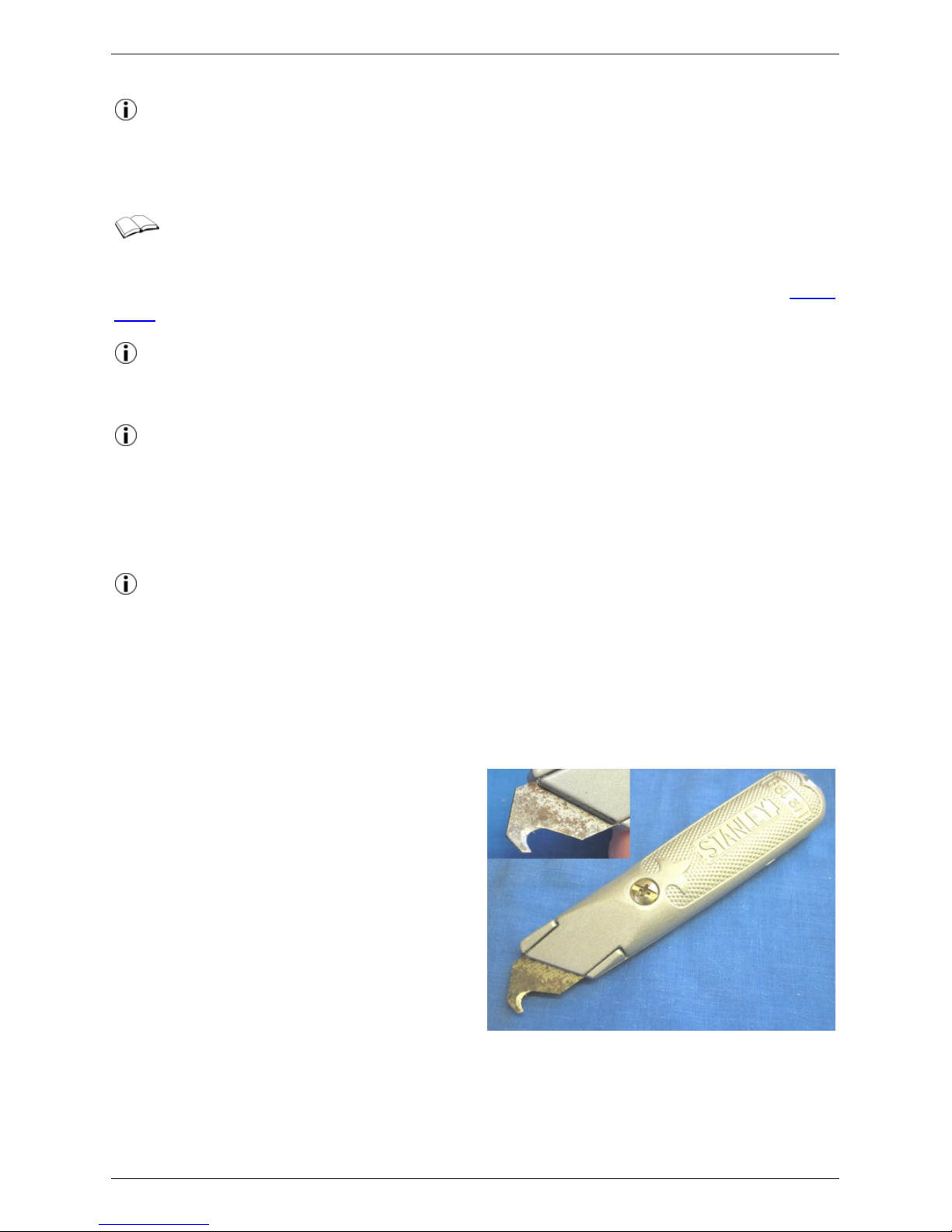
Components are attached to the fret by
small half-etched tags. These can be cut
through using a heavy c raft knife with an
old, stubby, blade (avoid the thin, pointed,
'scalpel' types, as they will break), against
a hard surface. We keep a rigid Stanley
knife expressly for this purpose, with an old
carpet trimming blade ground to shape as
shown.
Any remnants of the tag may be cleaned up
using a flat file. We have tried to avoid
putting tags on mating fac es, but there are
some instances where they need to be removed thoroughly.
Slots
General Notes 4/52
(c) PenBits Model Railways, All Rights Reserved 04/05/2017
Page 5
Some of the parts of our kits are designed
to fit, perpendic ularly, either into or
through slots in other parts. The slots are
intended to provide a loose sliding fit for
the other part. Because of variations in the
degree of etc hing (q.v., below), it is
possible that the fit will be looser or tighter
than ideal.
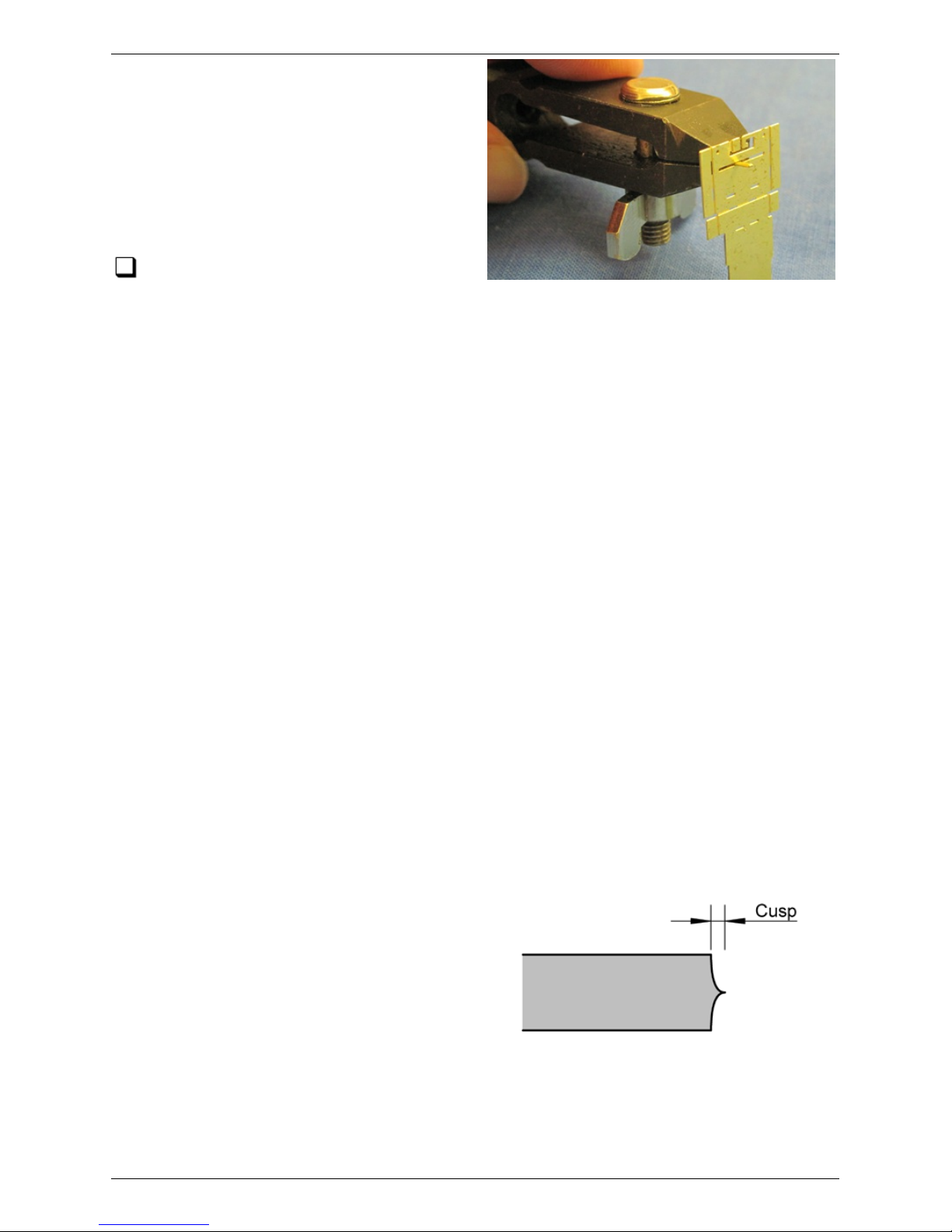
Check the width of eac h slot with a
piece of scrap etch before assembly,
preferably before folding the slotted part. If the scrap will not pass through, hold it in
pliers or a hand vice, as shown (though make sure the part is well supported), and
work it through the slot until the loose sliding fit is achieved. In tight spots, it is
possible to use a small drill held in a pin chuck as a file.
Degree of Etching
The etch is created for us by a third party industrial manufac turer using a process of
chemical erosion. The 'Degree of Etching', i.e. how long the metal sheet is left in the
chemical bath, is a variable which is set by the skill and judgement of the operator as
each batch of sheets is produced. That dictates that the sizes of the etched parts on
different sheets can vary, within a certain tolerance, around the nominally designed
values. The variation is more significant with the relatively thick materials, that we use
in the main structural parts of our kits, than it is with the thinner materials typically
used for detail parts.
The ideal degree of etc hing is indicated by the slots (see above), as manufac tured,
being just slightly on the tight side of the easy sliding fit required. The range of degree
of etc hing which we deem to be acceptable is from a 'lighter' etc h, in which the scrap
material has to be pushed through the slot quite firmly to achieve the c learance, to a
'heavier' etch, where the fit is a little loose. We have test built our kits from et c hes
across this range to confirm that they may be assembled successfully.
Cusps
The c hemical erosion process works equally
from each side of the metal, resulting in the
edges of the etch having shaped 'cusps' as
in the diagram here. On edges which will be
visible on the finished model, it is good
practice to file the edges of the metal flat.
Many of the edges on our kits are hidden
from view.
Where edges form joints with other
components, on a 'lighter' etch the edges may need to be filed to a flat surface to
achieve a fit, whereas with a 'heavier' etch one might leave more of the c usps in
place. In places which can't be reached by a file, e.g. in ac ute corners of the etc h,
the cusp may be pared away with a sharp knife.
General Notes 5/52
(c) PenBits Model Railways, All Rights Reserved 04/05/2017
Page 6
Folds
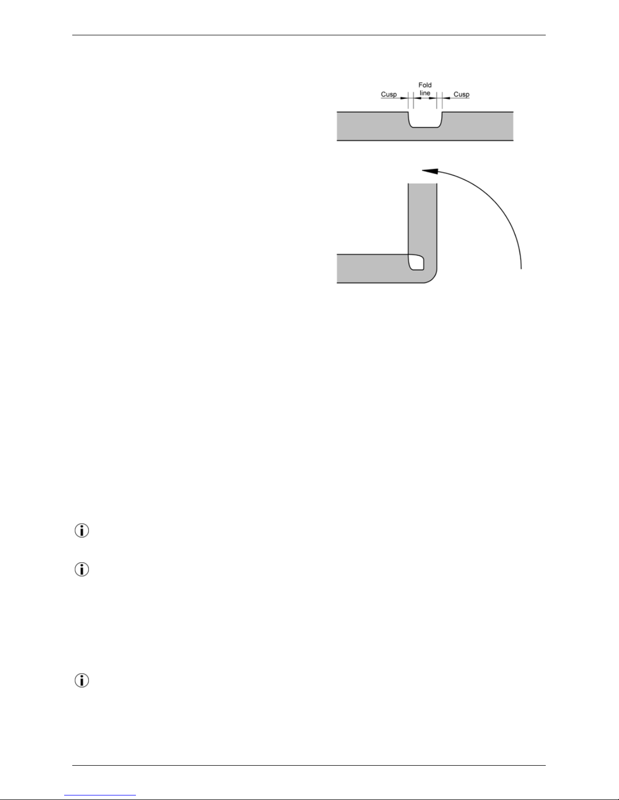
Folds are indicated on the etches by halfetched lines. Unless stated otherwise, all
folds are made at 90° with t he half-etched
line on the inside of the fold. Most folds
may be made by holding the larger part of
the workpiece in the fingers or, for smaller
items, a hand vice or similar clamp, and
then driving the fold from the smaller part
either by using smooth-jawed pliers or by
turning it over against a smooth, flat, hard
block of material such as hardwood, metal
or tufnol. For longer folds the workpiece
may be clamped between two flat, straight
edged pieces of similar material. Special
folding tools or bending bars are not
nec essary, though of course you may find
them useful if you have them.
Whichever way you make a fold, try not to force its location or direction, but let the
brass bend at its weakest point as determined by the c entre of the etc hed fold line.
This should result in a correctly positioned and symmetric fold as shown in the
diagram.
The act of making the fold will work- harden the metal along the line of the fold and
may even, especially with a lighter etch, cause it to yield on the outer corner of the
fold. Try, therefore, not to work a fold unnecessarily once made, as it will become
increasingly brittle and prone to breakage. In general, folds are reinforced with a fillet
of solder but this is explic itly dealt with in the instructions for each component.
Soldering
We use Carrs 145° wire solder with Carrs Green Label liquid flux, except where
stated otherwise.
Flux can be applied to the workpiece using either a brush or a pointed cocktail
st ick. It may help to reduce the surface tension of liquid flux, for example by
adding a drop of washing up liquid or ox-gall. The soldering iron bit is wiped on a damp
sponge, and then momentarily dipped in flux, before eac h use. A small amount of
solder is picked up on the bit and the bit applied to the workpiece, holding it there
until the solder 'flashes' into the joint; we are using relatively thick material so can
afford to linger with the iron and get plenty of heat to the job.
Flux residues should be neutralized and/or cleaned off after each working session.
Green Label flux may be rinsed away with water; a little added citric acid will
neutralize it. Liquid or paste fluxes can be washed away either with a proprietary flux
cleaner or a 50/50 mix of methylated spirits and water.
General Notes 6/52
(c) PenBits Model Railways, All Rights Reserved 04/05/2017
Page 7

Warranties
The procedures desc ribed in our instructions require the proprietary locomotive to be
dismantled and some of its components to be modified. The manufac turer's warranty
will almost c ertainly be rendered void by carrying out the modifications. The user
should ensure that the locomotive is free running and has no warranty issues before
commencing work.
Please follow the manufacturer's instructions for the dismantling of the locomotive.
Our instructions guide you in making modifications to components of the locomotive
and fitting the kit. The modifications, the kit and the instructions have been tested by
the kit designer and others to confirm that they are practical, serviceable and, when
used as intended, produce a working locomotive whose performance will bring much
pleasure. However, as the fitting of the kit by the user is out of our direct c ontrol, we
can make no warranty, expressed or implied, as to the performance and continued
serviceability of the locomotive following modification.
General Notes 7/52
(c) PenBits Model Railways, All Rights Reserved 04/05/2017
Page 8
Bearing Carriers
This stage of the assembly is fixing the subframe bearings into the bearing
carriers and folding up the carriers around the bearings. The carriers are located
on the fret in four frames, each of which folds up into a jig to help to fix the bearings
in the correct place. The carriers are a little fiddly, but worth spending time to get
right as they are one of the main functional parts of the suspension.
We find it useful to use two containers to store separately the components of
each bogie; 1kg margarine tubs are suitable. Within them we have 35mm film
cannisters, one for eac h axle, to keep the components for each wheelset together.
We mark the containers and cannisters to matc h the id marks etc hed on to the
subframes, bolsters and bearing carriers as explained below.
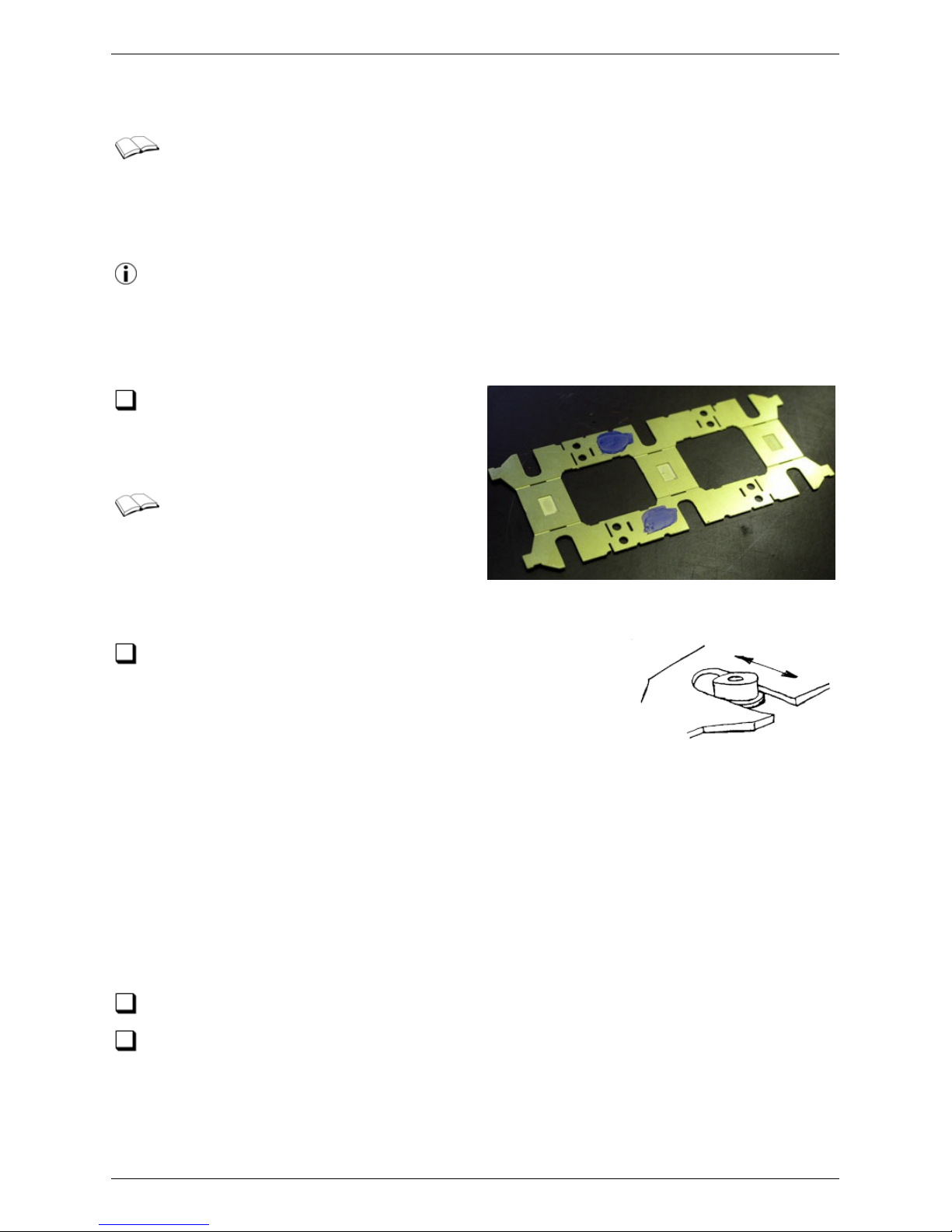
Separate the two subframe etches from
the fret. Remove any other c omponents
contained within eac h subframe etch and
store them safely.
Note that one of the subframes is
marked with a small triangular dimple.
You will find that one of the bolsters, and
one set of bearing carriers, are similarly
marked. You can use the marks, through all
subsequent work, to distinguish the components of each bogie.
Take one of the twelve axle bearings and test it in one
of the subframe axle slots. It should be a free sliding fit
but if it's a bit loose don't worry. It will more likely be a little
tight in which c ase gently file the vertical sides of the
bearing slot - take off a little at a time equally from each
side and try to keep the two sides vertical - until the free
sliding fit is achieved for the entire depth of the slot. Now test fit the other 11
bearings in the same slot. You should find that they are all about the same size. If
there is a variat ion, then you may wish to individually fit the bearings to the slots. You
will then need to preserve t he identity of each bearing through subsequent operations
(there are marks etched on the bearing c arriers and the subframes to assist with that
- see below). But do bear in mind that, as we have no coupling rods, the accuracy of
this fit is by no means as c ritical as it would be if we were building a st eam
locomotive. Whatever you choose to do, dress the remaining eleven bearing slots to
get the free sliding fit for eac h of the bearings.
Put the subframes in their containers safely to one side for now.
Test fit the axle bearings on the 2mm replacement axles. They should be a free
running fit. Remove any burrs or swarf from the front and rear faces of the
bearings.
Bearing Carrier Instructions for Six-wheel Bogies 8/52
(c) PenBits Model Railways, All Rights Reserved 04/05/2017
Page 9
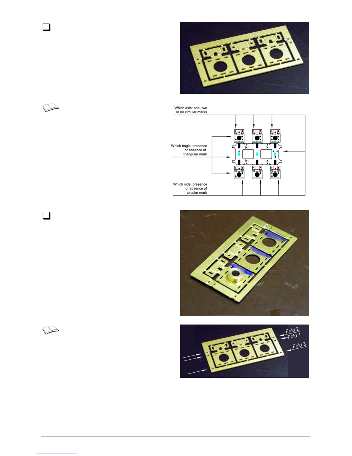
Remove the bearing carrier frames from
the main etch. DO NOT at this stage
separate the bearing carriers from the
frames.
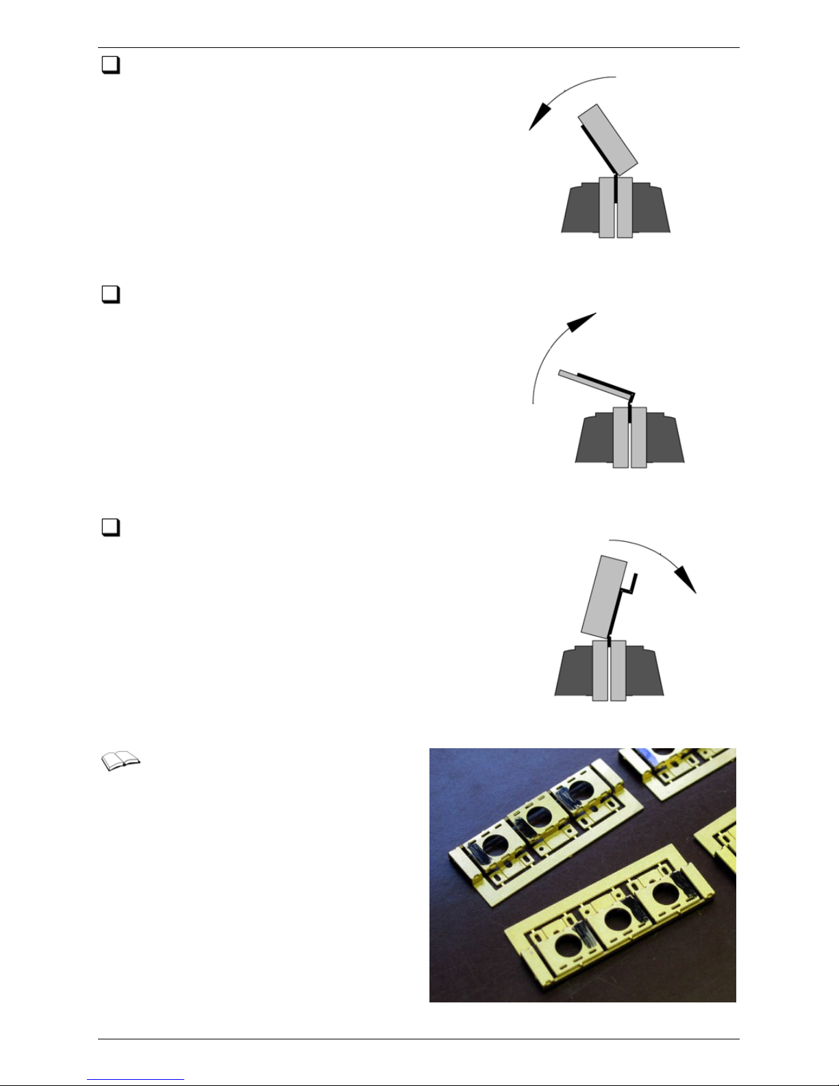
Note that the individual bearing
carriers eac h have small halfet c hed identification marks. You can
use these in conjunction with
corresponding marks on t he subframes
t o ensure that each carrier is always
mated with the same subframe slot.
Test fit the bearings in the large c entral
holes in the c arriers. The body of the
bearing (excluding the flange) should pass
through the hole. If necessary, gently
relieve the holes with a round needle file,
working evenly around the edges, until the
bearings pass through.
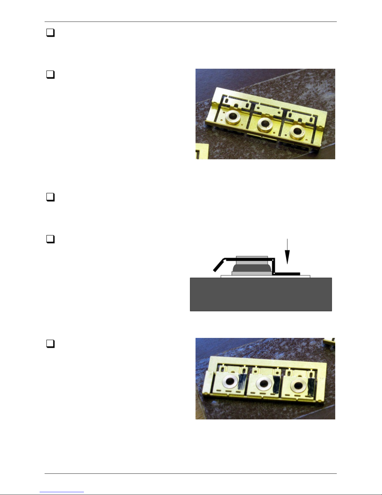
The folds in the bearing carrier
frames are best made in bending
bars, or between any two trued and parallel
surfac es c lamped together. Use a rigid
piece of flat material to make each bend
simultaneously along its whole length. This
will help minimise any unwanted distortion in
the fret.
Note that Fold 3 is a jig fold, made along the tags at the base of the carriers.
Bearing Carrier Instructions for Six-wheel Bogies 9/52
(c) PenBits Model Railways, All Rights Reserved 04/05/2017
Page 10
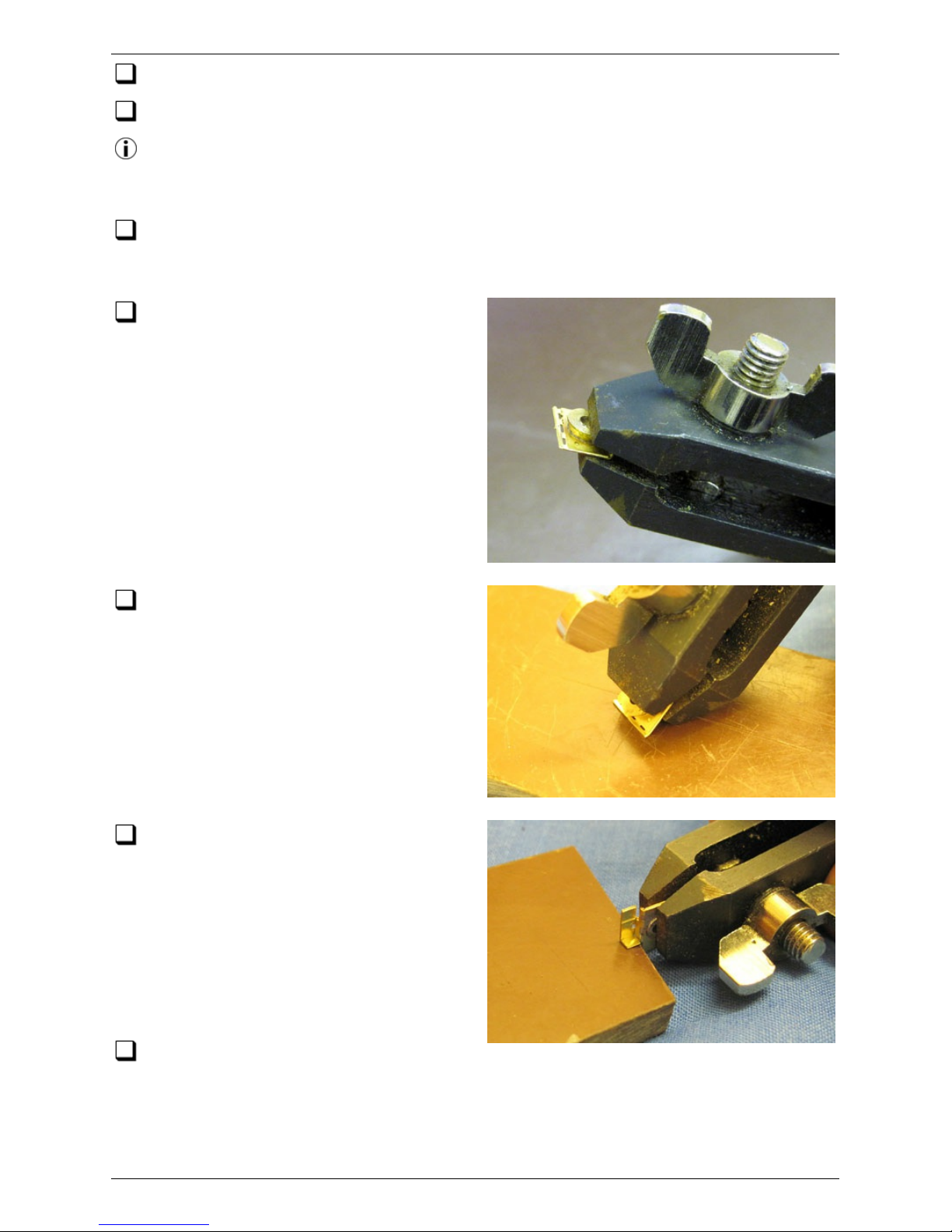
Make Fold 1, check that all sections of it are at
90°, and reinforce it with solder. Be sparing with
the solder; you don't really want to get any on the
carrier faces to the inside of the fold. Apply a small
amount of liquid flux to the slots on the outside of
t he fold, then get a small amount of solder on the
iron and touch it against the c entral slot on the
outside of the fold on eac h bearing carrier. You will
see the solder flash along the joint to the other
slots. Repeat for the two sections of fold on the
carrier frame.
Make Fold 2. You will need a thin, firm, flat piece
of material to drive this fold; a robust steel rule
(not a thin springy one!) works OK. If anything,
overfold beyond 90° just slightly.
Make Fold 3, to approximately 45°. Note that this
fold is along the line of the tags at the base of
each carrier, forming part of the frame assembly jig,
and is not a part of the finished carriers.
This is a view of the folded c arrier
frames. Fold 3 has been made to 90°
in this case, but anything over about 45°
will do.
Bearing Carrier Instructions for Six-wheel Bogies 10/52
(c) PenBits Model Railways, All Rights Reserved 04/05/2017
Page 11
Stick a length of double-sided tape, large enough to take one of the carrier
frames, onto a clean, flat, heatproof working surfac e. Ensure the tape is firmly
smoothed down on the surface, with no air bubbles or foreign bodies trapped
underneath.
Remove the backing paper from the
tape, take it to one side and place on it
t hree of the axle bearings, flanged face
down. Place the carrier frame, inverted as
shown, over the three bearings with the
bearings passing through the three holes.
Use the bac king paper to carry the three
bearings and frame on to the double sided
tape, then slide the backing paper away,
leaving the three bearings in contac t with
the tape and held in position by the c arrier
frame. Press the bearings firmly into place on the tape and remove the carrier frame.
Repeat for the other three carrier frames.
Using a c ocktail stick, place a thin fillet of multipurpose grease around the flange
root of each bearing. This will ensure that the area is kept free of solder when the
bearings are fixed into the carriers. An alternative is to use a permanent marker: the
ink should resist the flow of solder.
Place the carrier frame, the c orrect
way up, over the bearings and press
down firmly the back of the frame and
carriers, above Fold 2, on to the tape,
as shown here. The unflanged end of
each bearing should protrude from the
fac e of its c arrier by a very small amount
(not quite as much as in the sketc h),
and the faces of the c arriers should be
parallel with the end faces of the
bearings.
Using a c oc ktail stick, apply a small
amount of flux around the join between
the protruding part of each bearing and the
fac e of its carrier. Holding a bearing in
place with a heat insulating instrument, to
make sure it doesn't move, bring the iron
with a small amount of solder to the join
bet ween bearing and carrier, and let the
solder flash round the joint. Repeat for the
other bearings. A small amount of solder
may appear on the bearing outer surface under the inner face of the carrier but most
of the bearing outer surface, in particular within about 0.5mm of the flange, should be
free of solder.
Bearing Carrier Instructions for Six-wheel Bogies 11/52
(c) PenBits Model Railways, All Rights Reserved 04/05/2017
Page 12
Remove any excess solder from the front fac es of the bearings.
Free the fret from the working surface.
Weaken the bond of the double sided tape with a soak in methylated spirits and
slide a Stanley knife blade or a similar thin strip of metal under the fret and
bearings to break the bond of the tape without causing too much distortion.
Unfold Fold 3 and separate the individual bearing carrier assemblies from the frame.
Take care, as the top parts of the carriers are quite fragile at this stage: it may be
best to leave cleaning up the tags until after the folding and soldering stages below.
Taking eac h c arrier in turn, clamp it
firmly into a vice (a hand-held vice is
ideal for this) across the ends of the
be aring with the bottom of the bearing
carrier protruding. File away any remnants
of the tag from the lower edge of the
carrier.
Working against a hard, flat surface,
make the fold to form the bottom flange
of the bearing carrier.
Then, invert the c arrier in the vice so
that the carrier top is projecting. Fold in
the ears at the top of the carrier. You may
find that the ear catc hes against the top
flange: do not apply brute force, but adjust
Fold 2 and/or the direction of the applied
force, and you will find that it folds easily.
Folding against a block, as shown, gives a
good, tight fold.
On the inner c arriers (the ones without
a hole in their back face), apply a small amount of flux (cocktail stick!) to the folds
and butt joints around the top of the carrier and flash in some solder to reinforce the
folds and form a fillet between the lower edges of the ears and the top of the carrier
body. Clean off any solder which adheres to the outer faces of the ears. Ensure the
holes in the ears remain clear of solder.
Bearing Carrier Instructions for Six-wheel Bogies 12/52
(c) PenBits Model Railways, All Rights Reserved 04/05/2017
Page 13
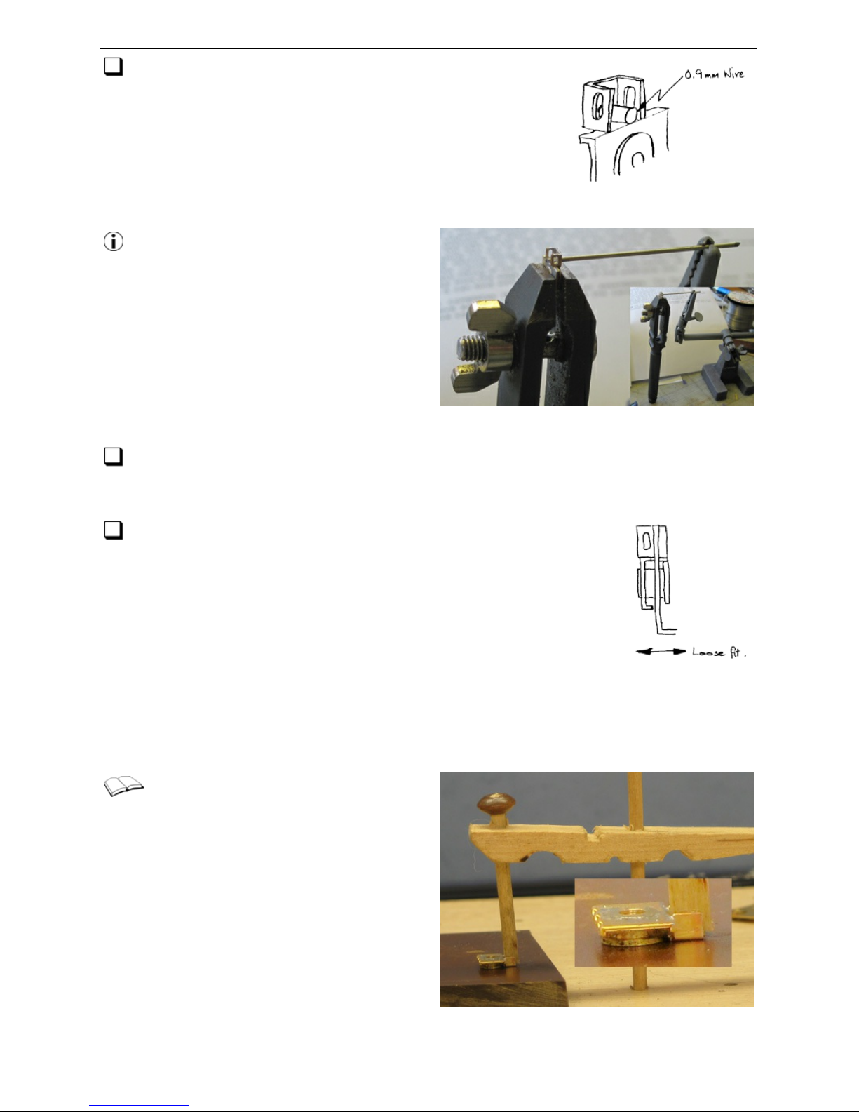
On the outer carriers, pass a piece of the 0.9mm nickel-
silver wire through the hole in the back of the carrier and
across the top, parallel to the line of the axle. With a small
amount of flux, solder the wire in place, at the same time
reinforcing the folds and butt joints around the top of the
carrier. Keep the bearing c lamped in the vice while soldering;
this will act as a heat sink and prevent melting of the joint
between the bearing and carrier.
We hold the 0.9mm wire in the correct
alignment with the bearing as shown
here. Clamp the wire horizontally in the
'helping hands' at a distance above the
bench that allows the hand vice, holding
t h e bearing, also to rest on the benc h.
Using one hand to steady the vice, the
other is free to wield the soldering iron.
Snip off the wire, close to the bearing,
when done, and it's ready for the next one.
Trim the wire and finish it flush to the front and back of the bearing with a file.
Clean off any solder which adheres to the outer faces of the ears. Ensure the
holes in the ears remain clear of solder.
Taking eac h subframe etch in turn, check that the carrier
assemblies can slide freely in their respective subframe slots
(see the next paragraph for a solution to bearing misalignment). It
is as well at this point to associate each bearing assembly with a
s lo t according to the markings on the bearing carriers and
subframes, whether or not you have individually matched the
bearings with slots. File away any burrs from the outer edges of
the c arrier tops. The fit along the line of the axle, i.e. of the
subframe plate between the bearing flange on one side and the inner fac ing edges of
the carrier on the other, should be quite loose to accommodate tilting of the axle.
Check that all traces of the tag are removed from the edge of the bottom face of the
carrier, as otherwise it c an bind with the lower edge of the subframe slot.
Although the aim is to have the
bearing flange parallel with the front
fac e of the c arrier, a certain amount of
misalignment c an be tolerated. If, however,
you find that the subframe side is 'pinched'
between the two, then an individual c arrier
assembly c an be c orrected by c lamping the
back of the top of the carrier against a flat
working surface. The soldering iron c an
then be applied to the bearing to melt the
joint between bearing and carrier and allow
the bac k of the bearing to be held down
against the same surface. T his should set the correct alignment.
Bearing Carrier Instructions for Six-wheel Bogies 13/52
(c) PenBits Model Railways, All Rights Reserved 04/05/2017
Page 14

That completes the bearing carrier assemblies. To finish off, clean them up to
remove any flux residues, and put the carriers and subframes safely away in their
respective containers.
Bearing Carrier Instructions for Six-wheel Bogies 14/52
(c) PenBits Model Railways, All Rights Reserved 04/05/2017
Page 15
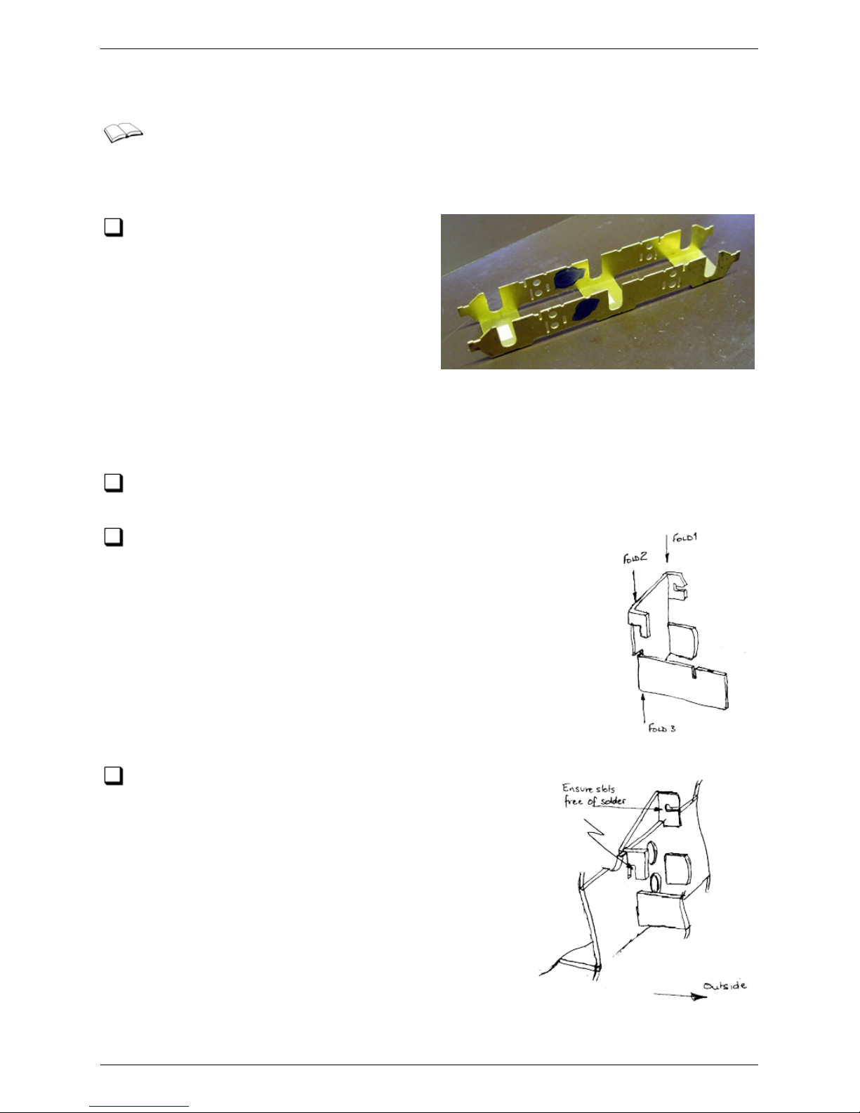
Subframes
This section desc ribes the construction of one of the two bogie subframes.
Main frames
Make the two main longitudinal folds,
each of which is in three parts c arried
over the transom sec tions under each axle
slot. Ensure they are at a true right angle
and reinforce them with a fillet of solder.
Take care to ensure that the region
immediately around the subframe bearing
slots, for at least about 1mm around the
edges of the slots, is kept free of solder.
Spring Seats
Remove the four spring seats from the etch. There are two of each hand for each
bogie.
Make folds 1, 2 and 3 in each spring seat as shown. DO NOT
make the fourth fold (on the reverse side of the spring seat
etch) at this stage.
From inside the subframes, fit each spring seat
through the slots in the side of the subframe
between the centre and outer axle slots. The back of
the spring seat should come up flush to the inside face
of the subframe side. Solder each spring seat in place,
ensuring that the slots for the springs themselves
remain free of solder. Make sure that the seats are as
far down in the mainframe slots as they will go. Check
that they are all at the same height by inverting the
subframes and resting the tops of the spring seats
against a flat surface.
Bachmann Class 47 Subframes 15/52
(c) PenBits Model Railways, All Rights Reserved 04/05/2017
Page 16
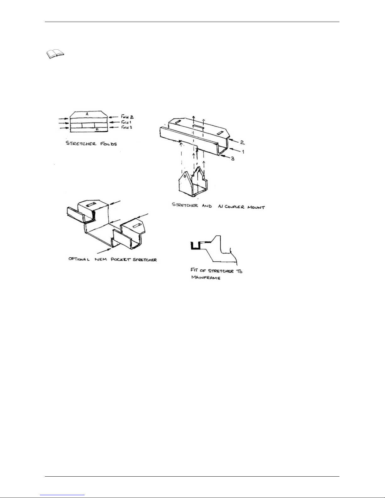
End Stretchers
There are two alternative sets of end stretchers. For kit PK001, use the
stretchers from etch F004. For kit PK002, which has the etched brake gear
components, use the stretc hers from etch F003.
F004 Stretchers
F003 Stretchers
Bachmann Class 47 Subframes 16/52
(c) PenBits Model Railways, All Rights Reserved 04/05/2017
Page 17
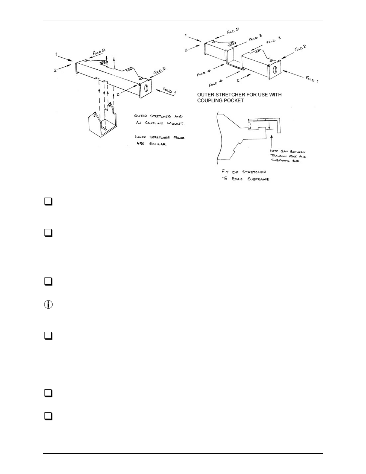
Remove the st retcher etches from the fret and c lean up. Choose the correct types
of stretcher depending on whether or not you wish to retain Bachmann's c oupling
pocket.
Fold up the stretchers as shown. For the F004 type, make fold 1 first and run some
solder along it. Then start fold 3, bending to 45 degrees or so. Finally, working with
fac e B against a hard flat surface and holding face A, simultaneously close up fold 3
and make fold 2. If using the NEM pocket stretchers, make the four additional folds as
shown.
Solder t he stretc hers in place, locating their slots over the tabs in the ends of the
subframes.
When fixing the stretchers to the subframes, it's convenient to work with the
subframes inverted and the stretchers supported on heatproof blocks of some kind,
leaving both hands free for the soldering operation.
If you wish to fit the Alex Jac kson coupler mounts, ensure the holes in the mounts
are opened out to about 0.3mm before fitting them to the stretc hers at the outer
ends of the bogies as shown.
Undertray and End Plates
Remove the two undertray plates from the fret. Make the folds at each end of
each plate, to about 80° rather than a full right-angle.
Fit the plates into the subframes, noting that the lugs on the sides of the plates
engage in the recesses in the lower edges of the subframe, and solder the joints
between the two.
Bachmann Class 47 Subframes 17/52
(c) PenBits Model Railways, All Rights Reserved 04/05/2017
Page 18

Fit the end plates across the subframe ends; support t hem against a block and
solder in place from the inside.
Bachmann Class 47 Subframes 18/52
(c) PenBits Model Railways, All Rights Reserved 04/05/2017
Page 19
Class 47 Bogie Bolster
These instructions describe the assembly of one of the two bogie bolsters. Note
that the photographs show a bolster of similar construction but with slight
differences in shape.
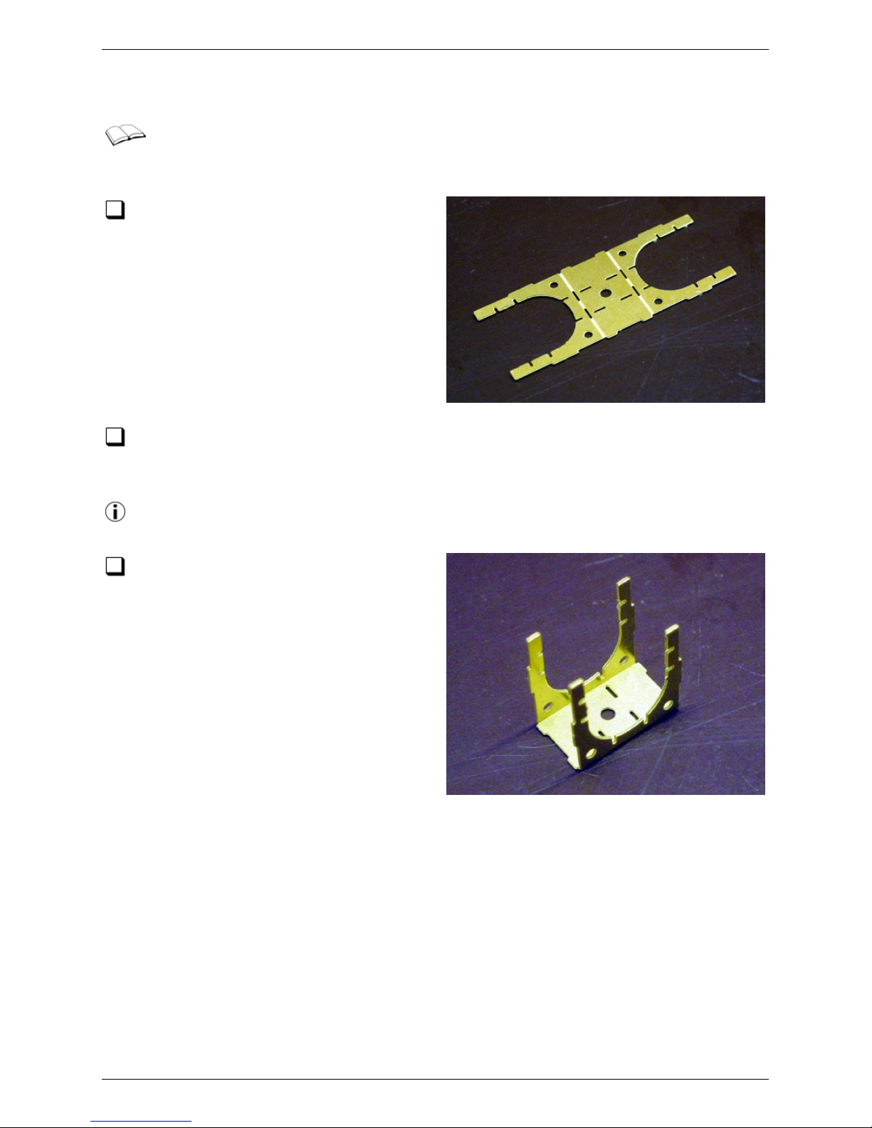
Remove the bolster centre etch from
the fret, taking c are not to distort the
'legs' of the etch.
The hole in the centre of the bolster is sized to take a 10BA sc rew. To use the
2mm pivot screw supplied in the kit, open out the hole to 2.0mm. Make sure the
hole is clean and thoroughly deburred.
Open out the holes using tapered broaches to ensure that centres are preserved.
Deburr the holes using a larger drill.
Make the two folds in the etch
Class 47 Bogie Bolster 19/52
(c) PenBits Model Railways, All Rights Reserved 04/05/2017
Page 20
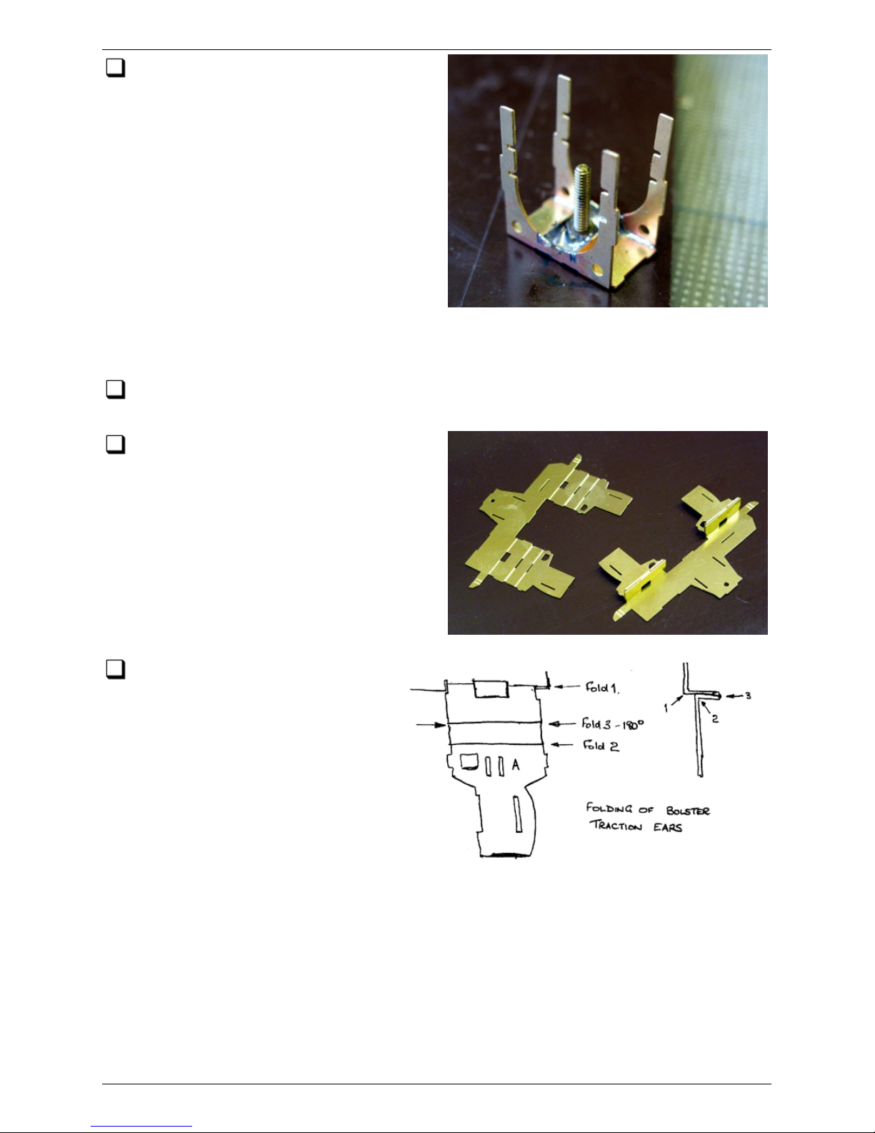
Remove the two Upper Stiffener etches
from the fret and fit them into place.
Clean up the faces of one of the 2mm brass
nuts to remove any machine oil and grease
and prepare for soldering. Take one of the
full-depth 2mm washers from the fret and
thread it on to one of the 2mm sc rews.
Apply some grease to the washer and the
top few threads of the screw. From the
outside, pass the sc rew through the central
hole in the top of the bolster frame and
thread on the nut. Sc rew the nut into place
between the upper stiffeners and tighten
up. Check that the nut is central between the stiffeners and flat to the fac e of the
bolster top. Run generous fillets of solder around the nut and the Upper Stiffeners.
Remove the screw from the nut (it should have been prevented from being
soldered in place by the grease).
Remove the t wo bolster side etc hes
from the fret.
Fold up the traction ears as
shown. Note that Fold 3 is 180°
with the etc hed slot on t he outside of
the fold. Make fold 1 first, then start
fold 3. Finally, gripping surface A with
pliers and supporting the main part of
the fret on a hard, flat surface, make
fold 2 and c omplete fold 3. Don't
apply any solder to these folds just
yet.
Class 47 Bogie Bolster 20/52
(c) PenBits Model Railways, All Rights Reserved 04/05/2017
Page 21
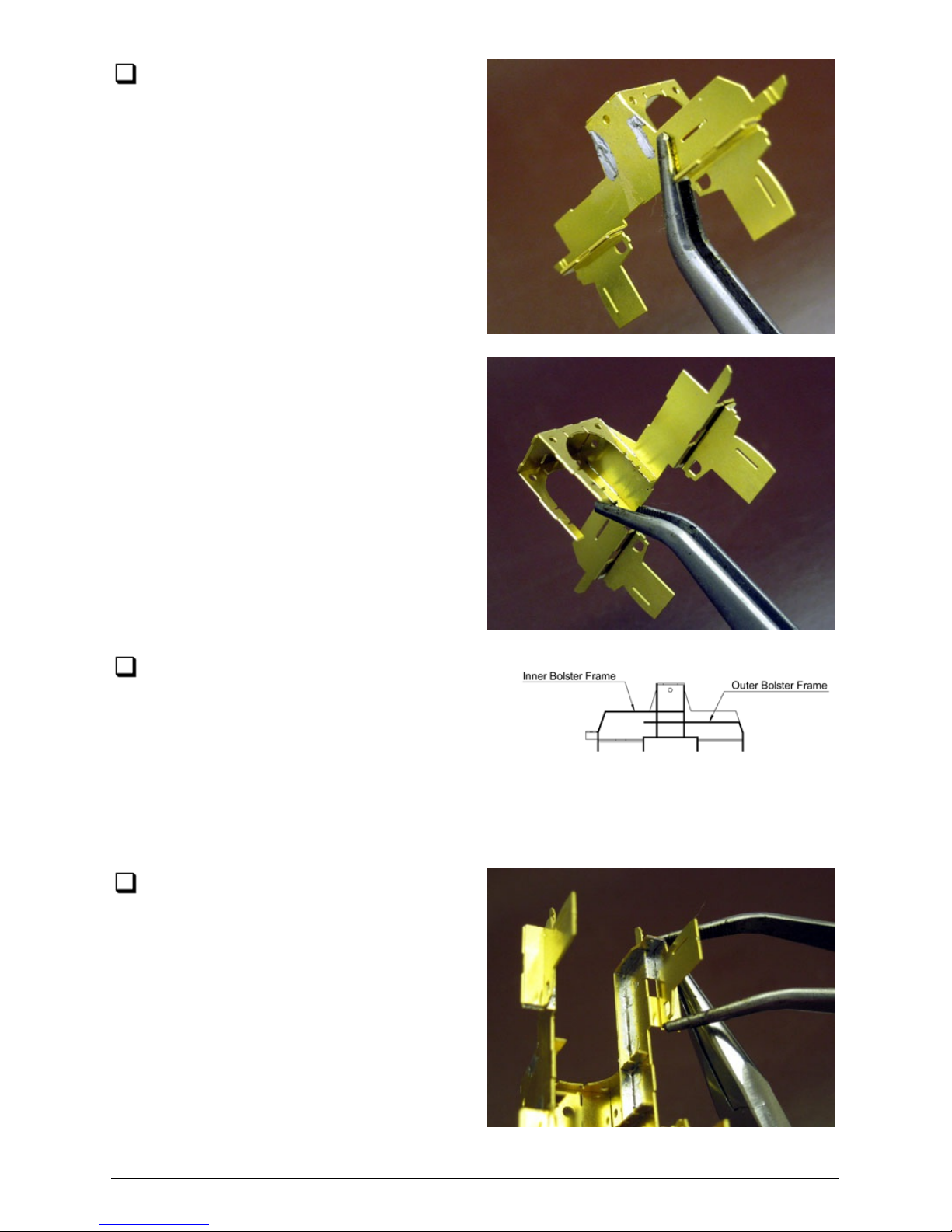
Hold the bolster centre and bolster
sides firmly together and tack solder
them from the outsides of the slots in the
bolster sides. Keep solder clear of the
places where the inner and outer bolster
frames will fit.
Remove two Inner Bolster Frame etches
from the fret and ensure that any tags are
cleaned up from faces which mate with the
inside face of the bolster sides. Fold them up
(the folds are less than 90°, as shown on the
folding diagram here, and the fold lines c losest
to the ends are on the outside of the fold), fit and solder them in place along the
bolster sides, noting that each has a slot which engages in a tab on the outside edge
of the traction ears.
For eac h traction ear, hold the two
laminations of the traction ear firmly
together and clamp the end of the Inner
Bolster Frame against its outside edge,
engaging the tab and slot. Ensuring that
the other folds on the ear are at 90°, run a
fillet of solder around the underneath of the
ear on the inside where it mates up with
the end of the Bolster Frame. Ensure that
the spring holes in the Inner Bolster Frames
are free of solder.
Class 47 Bogie Bolster 21/52
(c) PenBits Model Railways, All Rights Reserved 04/05/2017
Page 22
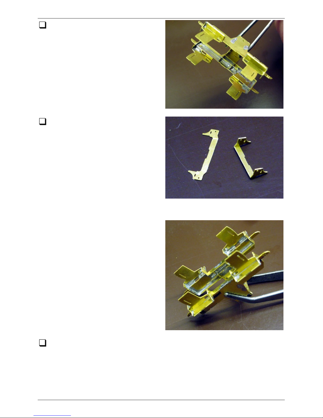
Similarly fold up and fit the two Outer
Bolster Frames.
Fold up and fit the Central Stiffeners /
Spring seats. The spring seats fit
between the inner edges of the traction
ears, engaging in similar slots to the Bolster
Frames on the outside. You will find, if you
start by sliding the 'noses' of the spring
seats between the opposing edges of the
traction ears, that the stiffeners can be
sprung into place between t he traction
ears. Again holding the 180° folds of each
traction ear firmly together, run a good
fillet of solder under the traction ear where
it engages with the Central Stiffener.
Pair up the bolster with its subframe, as designated by the presence or absence of
the tiny etched triangular marks. Note that the outer end of the bolster, as
distinguished by the horizontal parts of the outer bolster frame being lower than those
of the inner bolster frame, should be oriented towards t he coupling end of the
subframe.
Class 47 Bogie Bolster 22/52
(c) PenBits Model Railways, All Rights Reserved 04/05/2017
Page 23
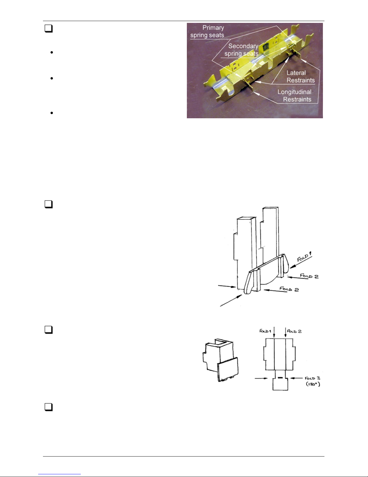
Check the bolster for dimensions and
squareness:
it should sit with the lower edges of all
four traction ears in contac t with a flat
surface,
the traction ears should just fit over
the lateral restraints on the subframe
sides, with a free sliding fit or just a
slight resistance,
the traction ears should just fit
between the longitudinal restraints on
the subframe sides, again with a free sliding fit.
A tight fit can be addressed in the first instance by light filing on the circular edges of
the traction ears or lateral restraints to remove etching cusps. Other adjustments may
be made by gentle tweaking of either the bolster assembly or the longitudinal
restraints. If you do need to tweak the bolster, try to end up with the faces of the
traction ears vertical; adjust the fit over the lateral ears by grasping firmly the central
arch as well as by rotating the outriggers.
Remove four secondary spring hanger detail
etches from the fret, fold them up and solder
them in place on the outside fac es of the traction
ears, engaging t heir tabs into the slots in the ears.
Remove the four bolster detail etches from
the fret and fold them up as shown. Store
them safely with the other bogie components
for now.
Clean up the bolster assembly to remove all flux residues. If you wish to chemically
blacken the bolster, do it at this stage. Do the four bolster detail etches at the
same time, they'll be fitted later.
Class 47 Bogie Bolster 23/52
(c) PenBits Model Railways, All Rights Reserved 04/05/2017
Page 24
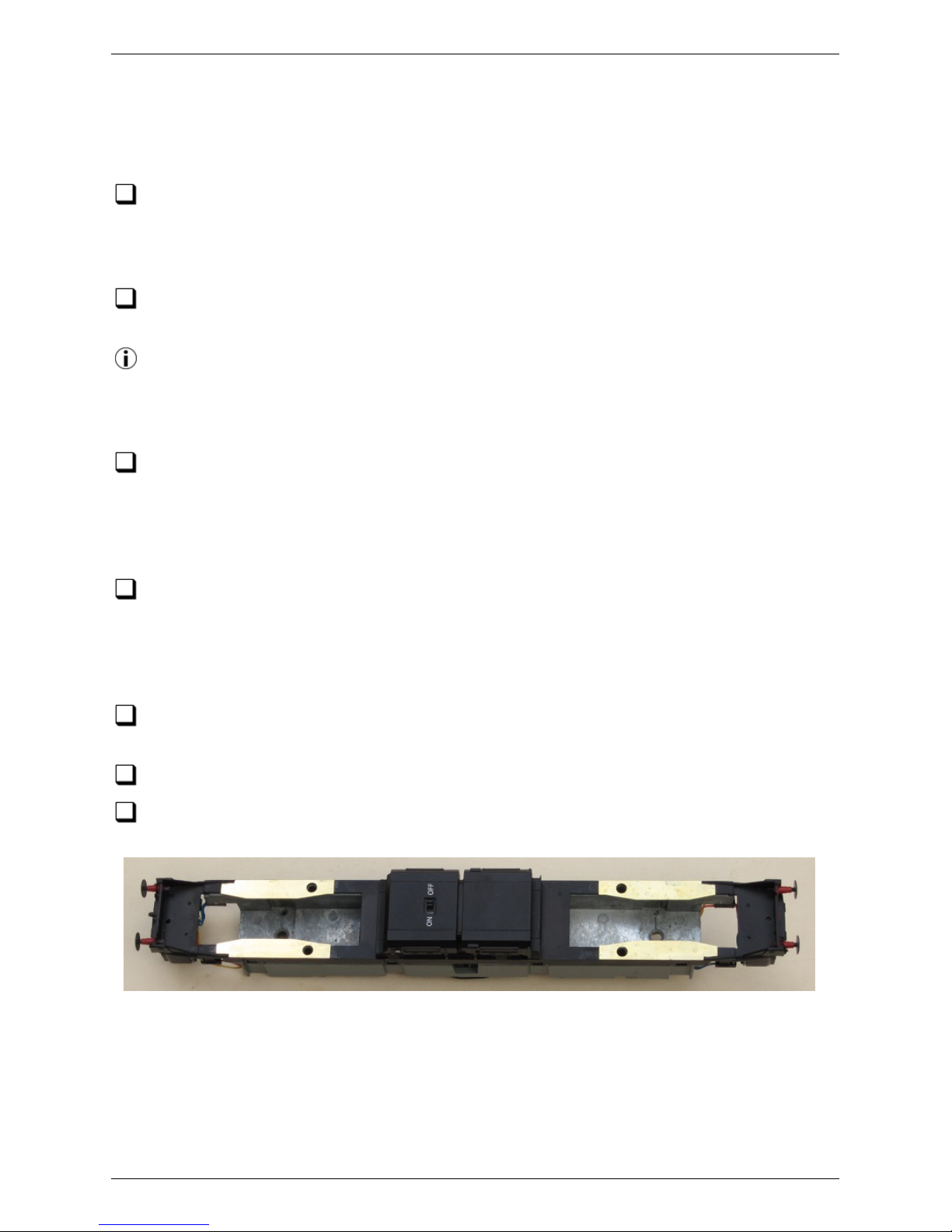
Bachmann 47: Preparing the
Locomotive
Following the manufacturers' recommendations for running-in, ensure that the
locomotive is performing smoothly and to your satisfaction generally. Deal with any
issues now, especially those covered by warranty or your basic statutory rights as
customer, before making any modifications.
Separate the body moulding from the chassis block of the locomotive ac c ording to
the manufac turer's instructions. Store the body retaining screws safely away.
Gently slide four cocktail sticks between the body and chassis block, one at each
body retaining clip (seated in a slot in the c lear plastic moulding underneath each
cab door window), just far enough to hold the c lips and body sides sufficiently apart
that the body may be slipped easily off the chassis block.
Make a note of the identification of t he terminals on the circuit board t o which the
two wires leading to each bogie are connected. Note also to which side of each
bogie they go. Pop off the insulated sleeves from the terminals and disconnec t the
wires leading to the bogies. It might be nec essary to desolder them but they may just
be passed through holes in the terminals and retained by the sleeves.
Select one of the bogies and undo the screw which retains the bogie pivot in the
chassis block. Drop the bogie out from t he bottom of the block. The c ardan shaft
joining the motor to the bogie will either come with the bogie or be retained at the
motor end. Either way, remove it but note that the ears on each end of the cardan
shaft are of subtly different shapes, so record which end is which.
Assign the bogie to one or other of your sets of etc hed bogie parts, marking the
bogie drive, drive shaft and chassis block ac c ordingly.
Similarly remove the other bogie.
Fix the four sole plates to the lower face of the chassis plastic moulding as shown,
using an epoxy resin glue or double-sided tape.
Bachmann 47 Chassis Mods 24/52
(c) PenBits Model Railways, All Rights Reserved 04/05/2017
Page 25
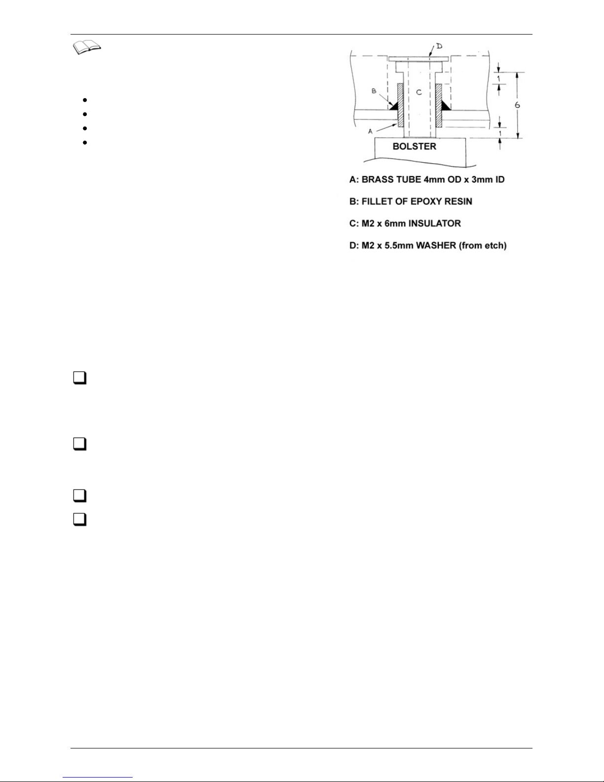
Bogie pivot c omponents are supplied in the
kit to mate with the M2 nuts fitted to the
tops of the bolsters
M2 x 10mm screws,
M2 x 6mm nylon insulators,
Brass tube 4mm OD x 3mm ID,
and M2 retaining washers (on the fret).
The diagram here shows the suggested pivot
arrangement to which the following instructions
apply. This arrangement is suitable for either
conventional or 'American' pick ups (with which
the bogie bolster is 'live'); the key attribute for
the latter being that the outer brass tube, and
therefore the loco chassis block, is electrically
insulated from the bolster top. The arrangement
also secures the bolster vertically, but allows some vertical movement to
accommodate adjustments in ride height.
Other arrangements are possible; the epoxy glue can be omitted and all c omponents
can be shortened, for instance. If required, a thin insulating washer c an then be
placed on top of the bolster to prevent electrical shorting to the brass tube.
Test the 4mm OD tube for a free sliding fit through the pivot holes in the loco's
chassis block. Open out the holes if and as necessary. Note that the fit is for the
tube passing perpendicularly through the hole; pitc h and roll movements of the bogie
are not accommodated at this pivot.
Cut two sections of the 4mm OD tube about 4mm in length. Check that the nylon
insulators supplied are a free fit through the tube, opening out the bore if
necessary.
Remove the M2 x 5.5mm diameter washers from the main fret.
For each pivot, offer up one of the bolsters to the loco chassis, with the
'shoulders' at the tops of its traction ears resting on the sole plates, and tape it in
place temporarily. Slide a piece of 40thou plastic card between the top of the bolster
and the chassis, c overing up the bolt hole. Put a ring of quick-set epoxy glue around
one of the 4mm tubes and place the tube through the pivot hole in the chassis to rest
on top of the plastic card, thereby positioning it about 1mm clear of the top of the
bolster. To make sure it is aligned c orrectly, when the epoxy is half set, untape the
bolster, pass the nylon insulator through the tube and sec ure it in place with the M2
screw and 5.5mm washer. Ensure that the bolster can rotate with the c hassis sole
plates resting on its shoulders, and allow the glue to set c ompletely.
Bachmann 47 Chassis Mods 25/52
(c) PenBits Model Railways, All Rights Reserved 04/05/2017
Page 26
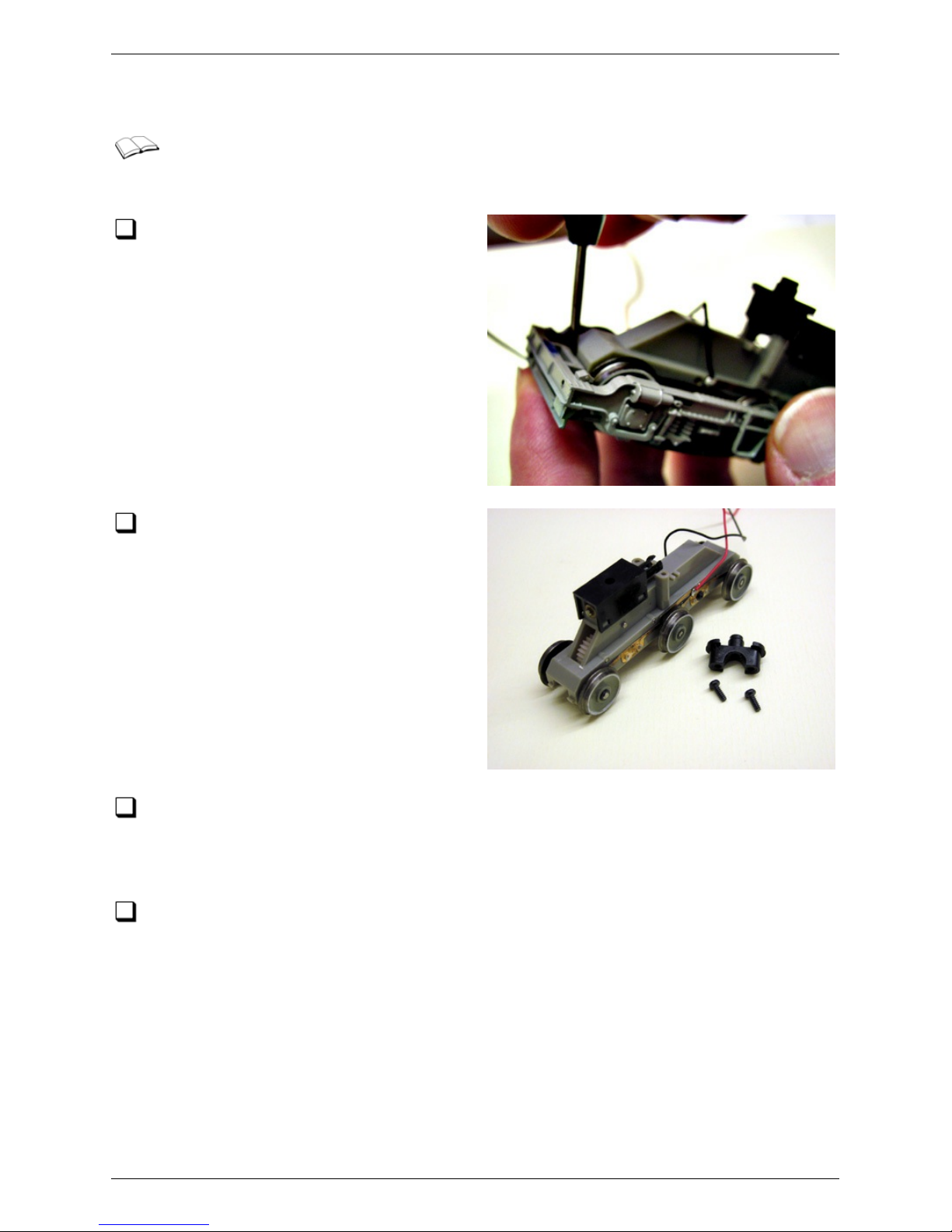
Modifying the Bogie Drive
This sec tion describes the operations involved in modifying the drive train for
one bogie. The illustrations are a mix of images from the Deltic and Class 47
models, which are identical in principle.
Using a small sc rewdriver, gently unclip
the bogie sideframe/undertray moulding
from the ends of the bogie drive unit. If you
wish to use the sideframes on your finished
loc o, take care not to damage the brake
shoe and step detail. Put the moulding
safely to one side for now.
Undo the two c ross- headed screws
retaining the bogie pivot to the tops of
the two pivot towers and remove the pivot.
These parts are not required for the
converted bogie.
Unclip the three wheelsets from the drive train moulding and put them to one side.
Rotate the three free idler gears, between the middle and inner axles, to feel how
free running they are, as you will need to reproduce this later when reassembling the
drive train.
Undo the cross-headed sc rews which retain the metal pickup strips on the side of
the drive train moulding. Remove the strips and, with a sharp knife, the moulded
pips which locate them. Put the pickup wires and strips to one side for reuse.
Gently press out the idler axles marked A and B. We found that the axles are a tight fit
in one side of the moulding only so, once you have removed the first one and thereby
determined which side that is, press them out from the tight side and, when the time
comes, replace them from the loose side.
When removing the idler axles, support the moulding on a hard surface with some kind
of slot or hole to receive t he axle.
Modifying the bogie drive 26/52
(c) PenBits Model Railways, All Rights Reserved 04/05/2017
Page 27
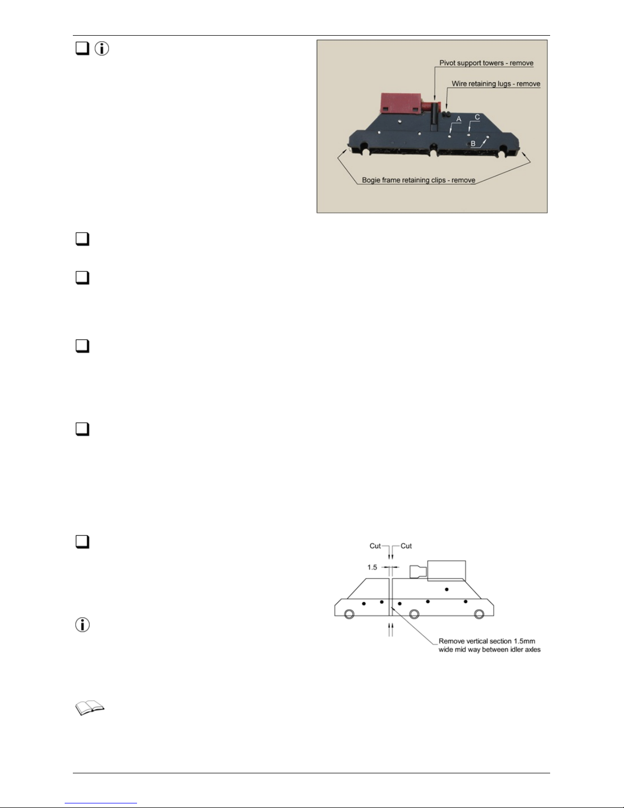
Remove the gears that were retained by axles A and B and put them to one side
for later.
Now remove axle C and its gear. Again put it and the axles to one side until later
but ensure that this gear is clearly distinguished from the other two in some way
as its teeth are of the opposite hand. It is possible to tell them apart by close
inspection but easier to keep them separate.
The drive train moulding and your fingers will by now be thoroughly lagged in
lubricating grease. Take a piece of kitchen paper towel and c lean things up, t hen
scrunch another c lean piece of towel into the underside of the moulding to cover the
remaining gears and protect them from the dust and swarf generated by the next
operation.
Referring to the illustration above, and using your favoured combination of razor
saws and craft knives or burrs, cutting discs and grinders in a mini electric drill,
remove the pivot support towers, wire retaining lugs and bogie frame retaining clips
from the moulding. Take them right down flush to the surrounding faces of the
moulding. Exercise some care as, in spite of being somewhat 'soft' and 'soapy', the
plastic can c rack in a brittle manner if overstressed. Take great care at all stages not
to damage the retaining lugs for the main axle bearings.
The drive train needs to be split
between the inner two axles, to allow
the suspension to articulate, by making
two c uts across the moulding as shown
here.
A razor saw may be used to make these
cuts. Take care that the moulding is
adequately supported while cutting - it's
helpful to have a solid block of material
which just fits between the sides of the moulding.
The kit is designed to allow the model to be driven on all six axles, i.e. as a C-C,
corresponding to the Co-Co arrangement of the prototype. It is, however,
possible to avoid a certain amount of complication by using the 4-wheel parts of the
drive as they are and assembling the loco as a B1-1B, in which configuration it will
Modifying the bogie drive 27/52
(c) PenBits Model Railways, All Rights Reserved 04/05/2017
Page 28
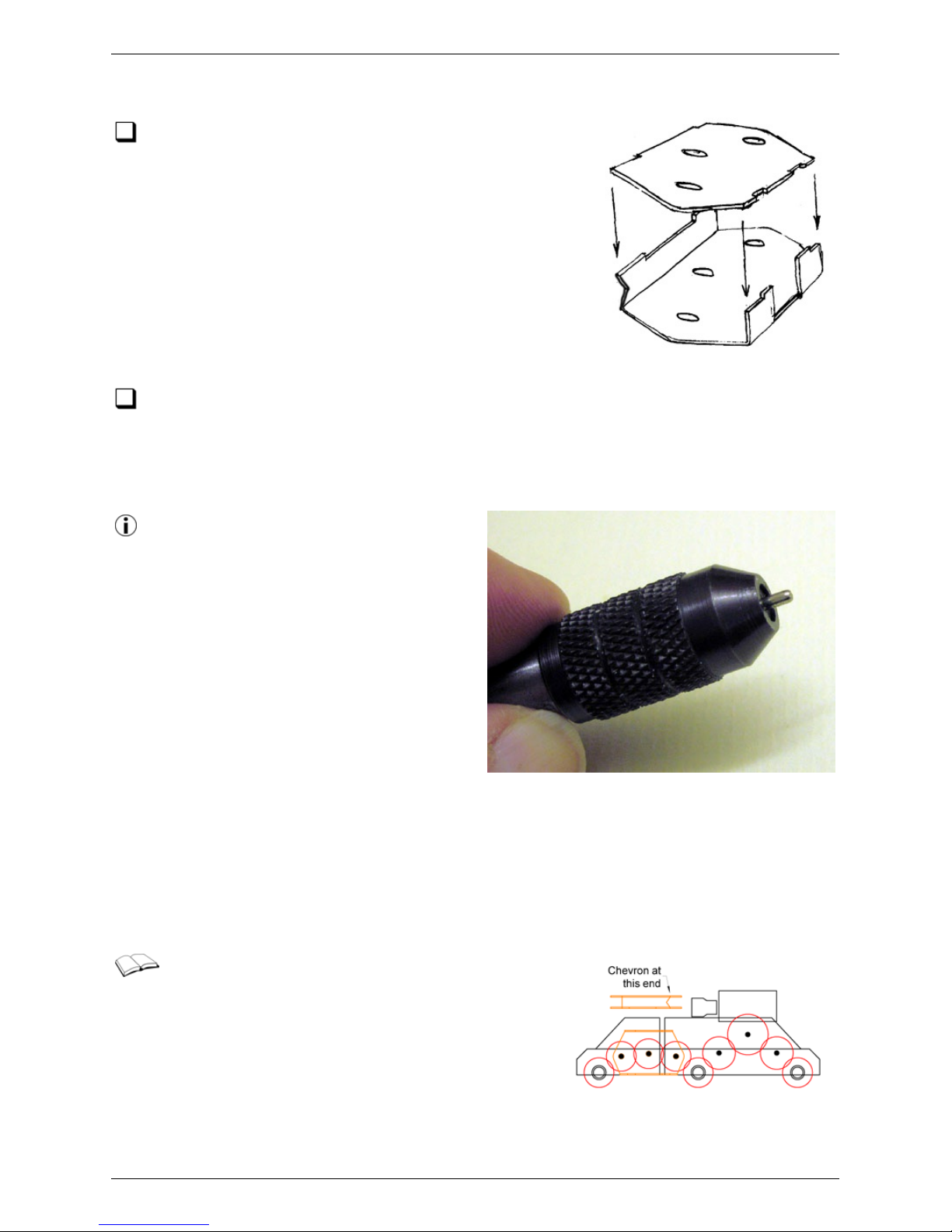
perform perfec tly adequately and retain muc h of its hauling capacity. If you wish to
take this option, you can skip the remaining steps in this section.
Remove the power transmission plate etc hes from
the fret. Check that the 1.5mm dia idler axles, that
you removed earlier from the drive train, are a free fit
through the holes in the plates (Not e: one pair of holes
is slightly larger than the others). Fold up the spac ers
on one of the plates and solder the plates together as
shown, making sure that the larger holes are opposite
each other. A chevron notc h in the top spacer of the
assembly indic ates at which end the larger holes are.
Check that the assembly is square.
Returning now to the three gears which you removed from the drivetrain, thin
dow n their widths over bosses such that they are a free fit between the two
power transmission plates, a dimension of about 2.9mm. There may be a small moulding
pip on the side of the gear which should be removed. Ensure that the thinned gears
each rotate freely on the idler axles.
The bosses of the plastic gears can be
thinned by filing them down. To hold the
gear while working it, clamp one of the idler
axles into a c ollet pin chuck with about
2.7mm projecting. The gear can then be
plac ed over the axle and worked with the
file while holding the pin c huck in the other
hand.
The filing operation will leave 'fuzzy c lods'
of deconstituted plastic around both the
outside edges of the bosses and the axle
holes. It is essential that this waste is
removed, using a sharp sc alpel blade, as
the smallest amount will cause the gears to run tight on the axles or bind against the
transmission plates. Use the scalpel to put the tiniest of bevels around the
circumference of the axle holes and outer edge of the bosses. Finish c leaning with a
wash of methylated spirits scrubbed by an old toothbrush. Do not be tempted to
relieve the axle holes with a broach or reamer - any tightness will be down to dust or
swarf.
We now re-assemble the drive train in its
articulated form as per the diagram here.
Modifying the bogie drive 28/52
(c) PenBits Model Railways, All Rights Reserved 04/05/2017
Page 29
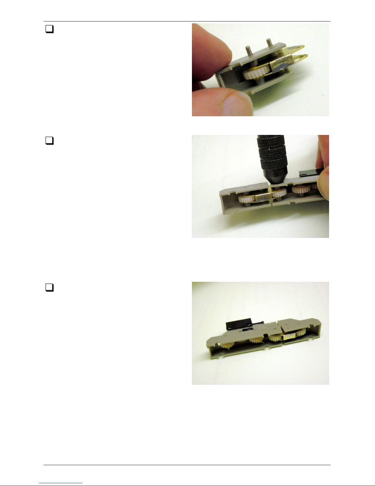
Take the smaller part of the drive train
moulding and insert the transmission
plate assembly into it, with the c hevron in
the top spacer facing outwards, such that
the two smaller holes line up with the idler
axle holes in the moulding. Slide the unique
one of the three idler gears into position
between the plates, lining up with the axle
hole in the middle of the plates. Press the
idler axle into place to retain the gear.
Similarly fit one of the other two gears and
axles in the remaining idler axle position. Check that the gears rotate freely.
Now slide the 'chevron' end of the
transmission plate assembly into the cut
end of the larger part of the drive train
moulding. Slide the remaining idler gear
between the plates, line it up with the
holes in the plates, line up the holes in the
plates with the holes in the moulding, and
insert the idler axle to retain the axle and
plates in position. Check for freedom of
movement between the two parts of the
drive train moulding: it should be sufficient
for the inner axle to move up and down
about 1mm with respect to an imaginary
line joining the centres of the other two axles. It will probably be much more than this,
but if there is a problem just file back the c ut edges of the moulding where they come
close.
Check that the three idler gears rotate
freely together as they did before
disassembly. If any tightness is present,
strip down the gears and ensure that they
are clean and free from any kind of swarf or
dust residues.
Modifying the bogie drive 29/52
(c) PenBits Model Railways, All Rights Reserved 04/05/2017
Page 30
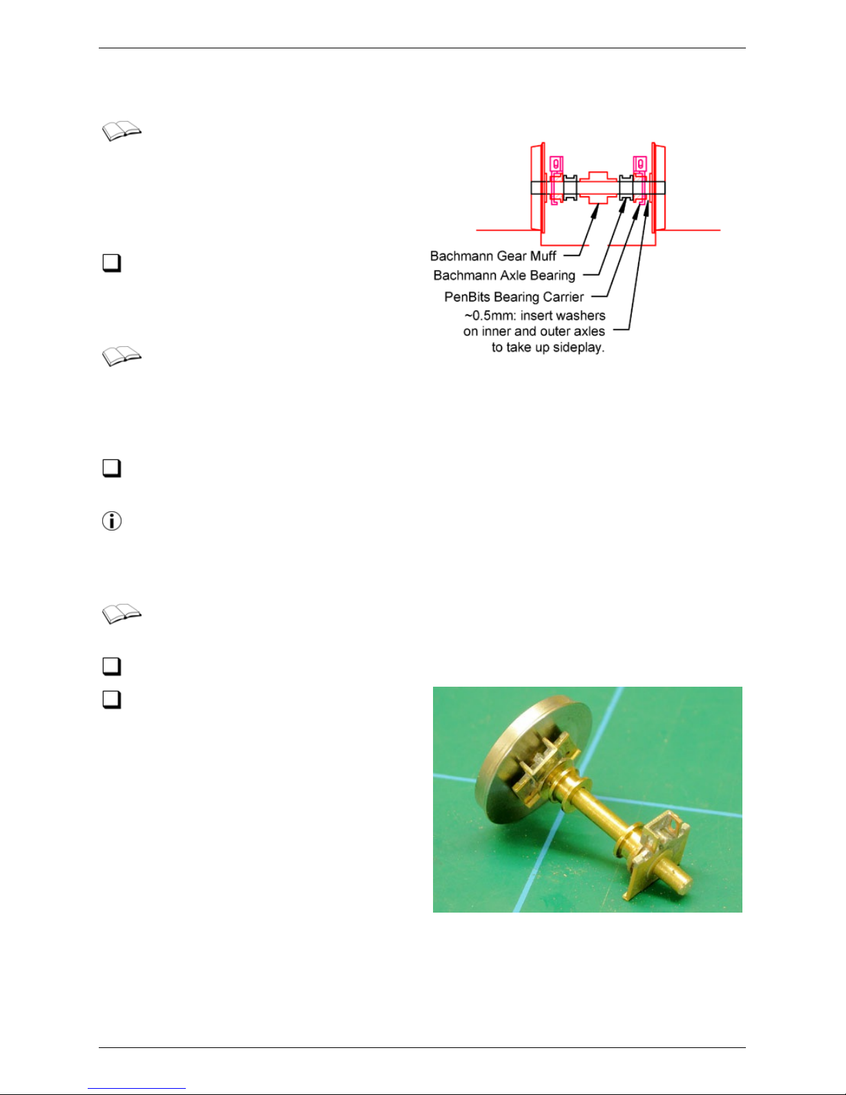
Fitting Wheelsets
Six 2mm diameter plain-ended axles
are required. Pin-pointed ends
should be removed. If you are using
ready-assembled wheelsets it will be
necessary to remove at least one of the
wheels from the axle.
Dismantle the Bachmann driven
wheelsets. Recover the final drive
gears and the axle bearings. Discard the
wheels and axles.
The Bac hmann axle bearings need
to be opened out to ac c ommodate
differential movements of t he axles in the
suspension whilst at the same time holding the drive gears in mesh and transmitting
the tractive forces from the drive train to the axles.
Open out the internal diameters of each of the Bachmann axle bearings from 2.0 to
about 2.1 to 2.2 mm.
We found that the tapered end of a 2.3mm cutting broach was about 2.1mm
diameter so used that to cut half way through the bearing from eac h side, finishing
off with a smooth broach. Not a tec hnique for the purist, perhaps, but adequate for
our purpose. Alternatively, using a lathe, we have simply drilled through the bearings.
The following operations chec k the differential movement between the drive
train and the bogie subframe. Repeat them for each bogie in turn.
Find the brass bogie subframe and bearing carriers for the bogie.
Taking the new axles one at a time, and
with regard to the identification marks
on the bearing c arriers and subframes, slide
on to each axle a bearing carrier, two
Bachmann axle bearings and the second
bearing carrier. Note that the ears at the
tops of the bearing carriers face outwards
towards the ends of the axle.
Fitting Wheelsets 30/52
(c) PenBits Model Railways, All Rights Reserved 04/05/2017
Page 31
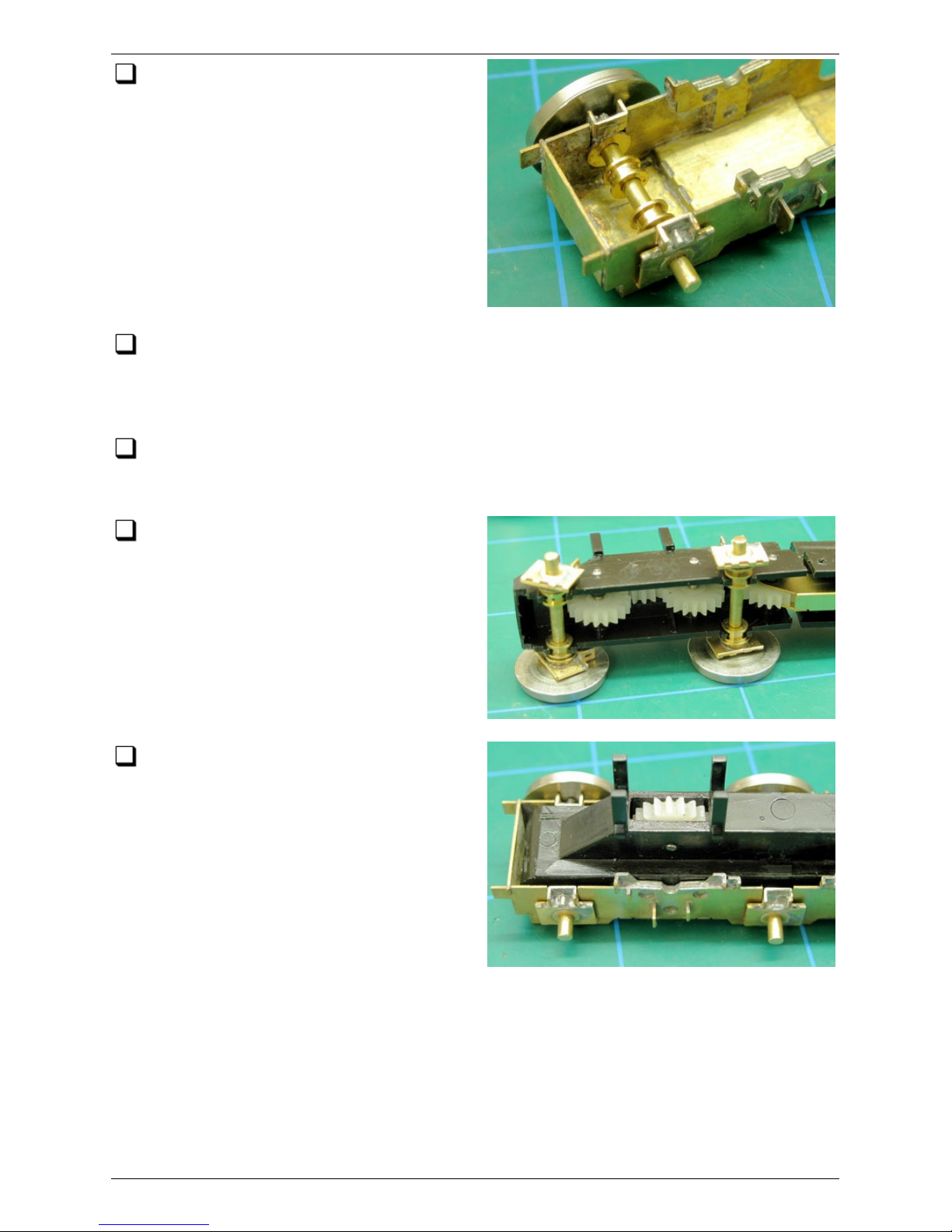
Insert each axle into its slots in the
Subframe, and check for free vertical
sliding of the bearings in the slots, firstly
with the axle horizontal, and again with the
axle tilted such that one wheel is raised up
to about 1mm above the other.
Orientate the brass Subframe and the Drive Unit. The 'four-wheeled' part of the
drive unit goes towards the outer (i.e. coupling) end of the bogie, driving the
centre and outer axles, with the socket for the cardan shaft fac ing the inner end of
the bogie.
Test the fit of the drive unit within the envelope of the subframe, again both
aligned with the subframe and also tilted slightly. Remove any remaining lumps or
bumps from the drive moulding if these interfere with the movement.
Take the c entre and outer axles and
clip them in to the drive unit using the
Bachmann bearings.
Fit the drive unit into the subframe,
engaging the four bearing c arriers into
the slots in the subframe. Holding the drive
unit with one hand and the subframe with
the other, c hec k that the drive unit can
move freely up and down relative to the
subframe with the carriers sliding in their
slots. At rest the tops of the carriers will be
level with the tops of the subframes. The
suspension is designed to deflect ±0.5mm,
so the free movement needs t o be
maintained both when the base of the drive unit is parallel with the base of the
subframe, and when one axle is raised up to 1mm with respect to the other. If there is
any binding when the units are parallel, c hec k the movement of individual carriers in
their slots and c orrect as necessary. If there is binding when one axle is raised, open
out the Bachmann axle bearings just a fraction more, up to a maximum of 2.3mm.
Fitting Wheelsets 31/52
(c) PenBits Model Railways, All Rights Reserved 04/05/2017
Page 32
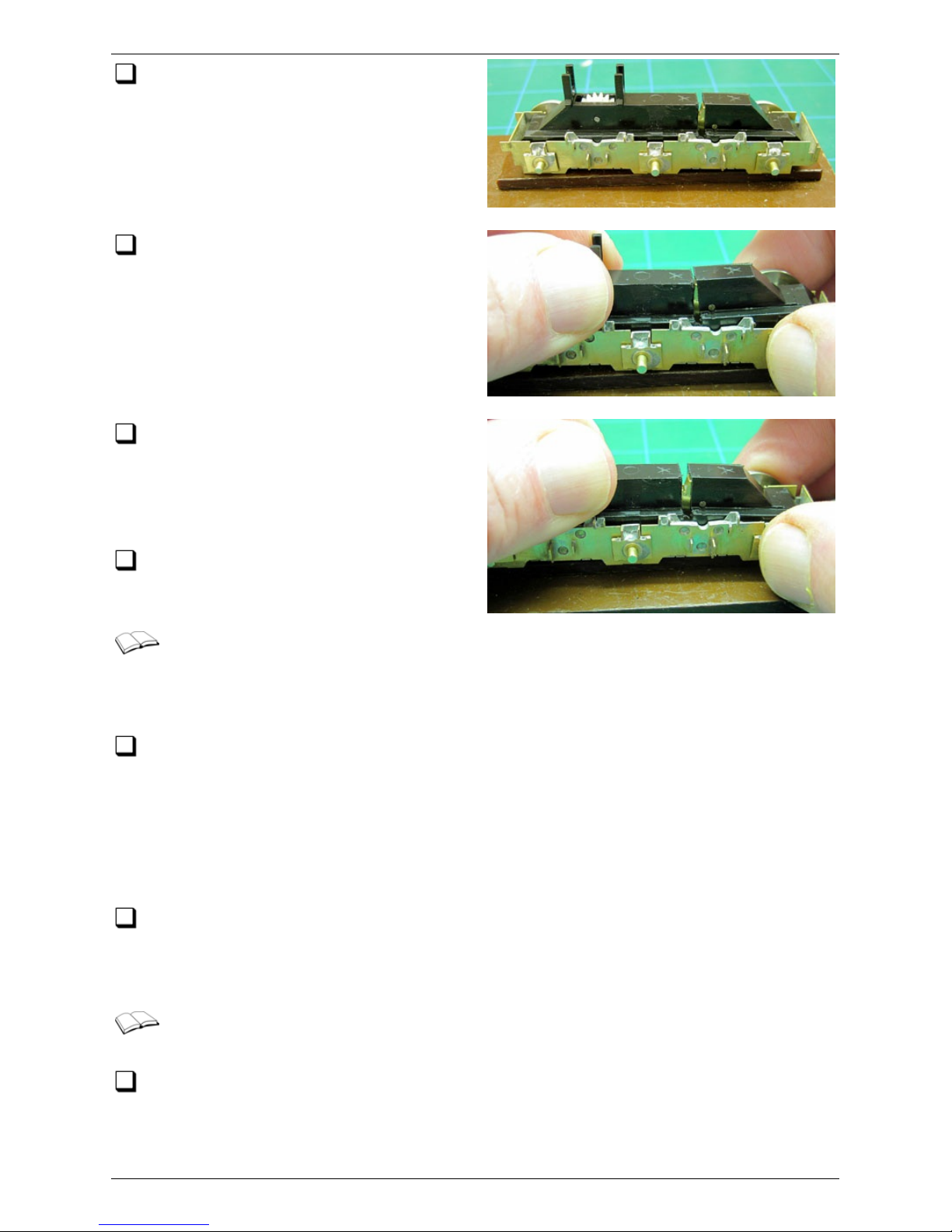
If you are having three driven axles,
remove the drive unit from the subframe
and c lip the third axle into place. Replace
the drive unit in the subframe, now
engaging all six of the bearing c arriers into
their slots.
Holding the 'four-wheeled' part of the
drive unit suc h that the tops of all four
of its bearing carriers are level with the top
of the subframe sides, chec k that the third
axle has at least ±0.5mm of vertical travel.
If this is not the case, check for free
movement of the individual carriers in
their slots and then, if required, open out
the Bachmann bearings a little more, on this
axle only, up to a maximum of 2.3mm.
That concludes the test. Unclip the
axles from the Drive Unit and store them
in their respective containers.
We now use one of the inner or outer axles, still with its bearing c arriers fitted,
to check for lateral play. If you are using ready assembled wheelsets and have
one wheel already fitted to each axle, you will need to vary the operations slightly to
suit.
Fit the wheels to the axle to the c orrect back-to- bac k measurement. Test fit the
axle in the bogie subframe to determine the amount of lateral play. There should be
just a little; enough to allow the wheelset to tilt such that the wheel on one side is
raised about 1mm with respect to that on the other. If necessary, dismantle the
wheelset and fit full- and half-width 2mm washers (supplied on the fret) between the
bearing carriers and wheels, until this condition is met. If there is insufficient play,
even with no washers fitted, reduce the inner width of the wheel bosses accordingly.
Record the washer configuration you arrived at and dismantle the wheelset. If you
had to reduce the inner wheel bosses, repeat the operation on the remaining
wheels. Take off an extra 0.5mm on the wheels for the two centre axles, subject to
not going beyond the line of the inner wheel rim.
Now we can fit the Bachmann gears to the new axles and assemble the
wheelsets. Do the following for each axle.
If you have one wheel already fitted to the axle, slide on the required number of
washers adjacent to that wheel, then the bearing c arrier (ears facing the wheel),
then a Bachmann drive bearing.
Fitting Wheelsets 32/52
(c) PenBits Model Railways, All Rights Reserved 04/05/2017
Page 33

If it is a driven axle, slide one of the Bachmann final drive gears into position
centrally. The gear should be a tight fit on to the axle, sufficient to transmit drive
forces without slipping.
Slide the Bachmann bearings, then the bearing carriers, then any washers required,
on to the axle.
Fit the wheels to the axle to the correct back- to-back measurement. If you are
using the 'American' pickup system make sure that the insulated wheel is adjacent
to the carrier for the insulated side of the bogie.
Test fit eac h inner and outer axle in its slot to c onfirm that the correct number of
spacing washers has been fitted.
Lubricate the bearings with a light machine oil and ensure that the oil is taken in to
all the axle-bearing interfac es.
That completes the assembly of the wheelsets.
Fitting Wheelsets 33/52
(c) PenBits Model Railways, All Rights Reserved 04/05/2017
Page 34
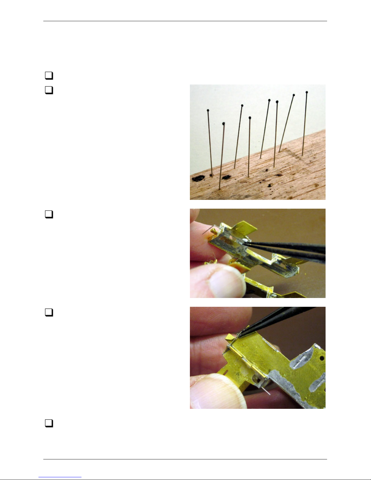
Springs, Bogie Assembly and
Rolling Test
Cut eight lengths of the primary spring wire, each 32mm long.
Degrease t he wires and apply, to one
end of each wire, a bead of fast setting
epoxy resin about 1mm diameter, i.e. just
large enough to prevent the springs being
pulled through the holes in the ears of the
central bearing carriers. Put the springs to
one side while the resin sets.
Cut eight lengths of the secondary
spring wire, each 24mm long. Make a
bend in each wire, 8mm from one end, of
just slightly less than 90°. Fold up the four
spring retaining ears on the c orners of each
bolster. Pass the longer arms of the wires
through the holes in the secondary spring
seats...
...and clip the shorter arms into the
spring retaining ears. Put the bolsters
safely to one side.
Return to the primary suspension wires and check that the epoxy resin beads have
set hard.
Springs, Bogie Assembly and Rolling Test 34/52
(c) PenBits Model Railways, All Rights Reserved 04/05/2017
Page 35
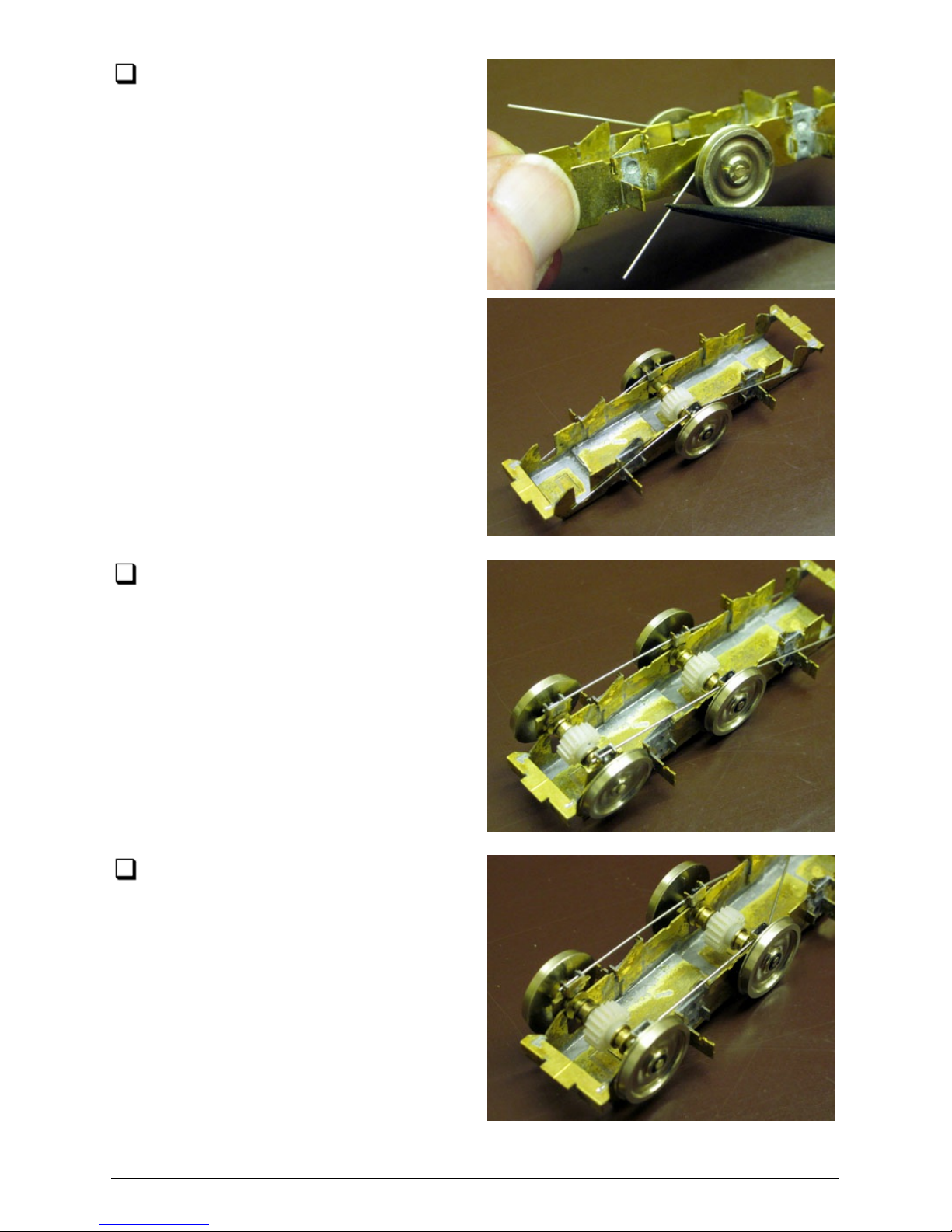
Taking one bogie subframe, fit the
middle wheelset. Take four of the
primary springs and insert one through each
of the four holes in the ears of the bearing
carriers, feeding them through until retained
by the epoxy beads.
Rest the springs on top of the
secondary spring seats. Taking one of
the outer wheelsets, thread the free ends
of two of the springs through the slots in
the ears of the bearing carriers...
... and locate the bearings in the tops
of their mainframe slots.
Springs, Bogie Assembly and Rolling Test 35/52
(c) PenBits Model Railways, All Rights Reserved 04/05/2017
Page 36
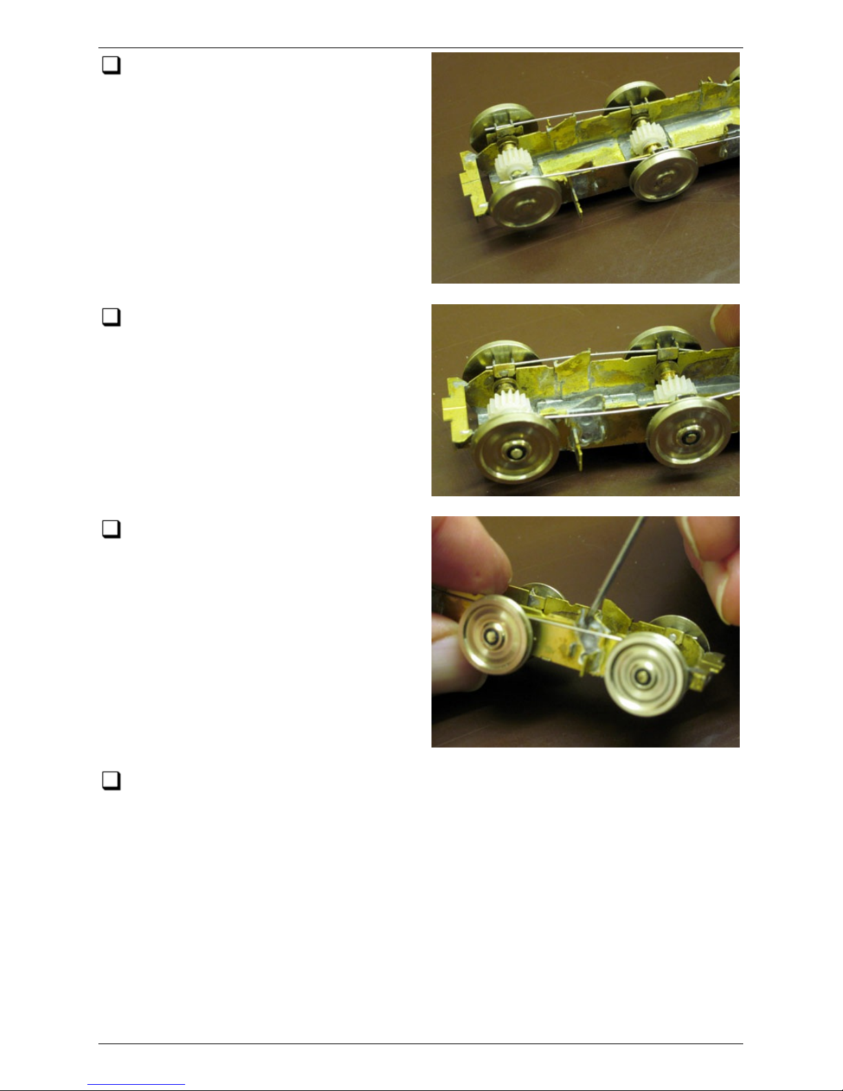
Using a small screwdriver t o manipulate
the springs, bend them outwards to
slide over the secondary spring seats...
... and then part way down the
outsides of the primary spring seats.
Finally push each spring downwards
until it snaps into its primary spring
seat.
Repeat this operation for the other outer wheelset.
Springs, Bogie Assembly and Rolling Test 36/52
(c) PenBits Model Railways, All Rights Reserved 04/05/2017
Page 37
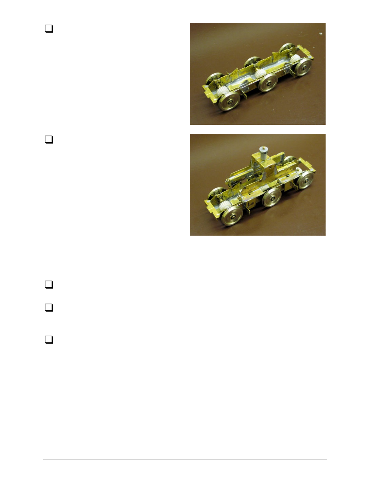
You now have a rolling bogie with fully
functioning equalized primary
suspension. Do a hand-powered rolling test
to c hec k for any tight bearings, wobbly
wheels etc. It is easiest to correct such
things at this stage.
Now take the bolster, make sure it is
the right way round, and slide it into
place over the subframe. As you do so,
push it to one side and you should find that
the sec ondary springs on that side will snap
in to place in their spring seats. On the
other side, working through the slots in the
tops of the traction ears with a small flat
bladed screwdriver, push the sec ondary
springs outwards and slide them down over
their spring seats until they also snap into
place.
NOTE: To remove the bolster, DO NOT attempt to reverse this method and flip the
springs out of their seats, but remove each spring completely from the bolster, then
lift it away from the subframe.
Repeat the above operations for the other bogie so that you now have two rolling
bogies.
You c an now fit the bogies into the chassis block of the loco and do a rolling test
to c hec k ride height, body clearances, ability to handle curves and suspension
characteristics.
Remove the bogies from the loco and dismantle them ready for the next stage.
To remove the bolsters, remove the four secondary springs altogether rather than
attempting to unclip them from their seats.
To remove t he wheelsets from the subframe, use the sc rewdriver to press down the
primary springs and pop them out to rest on the outsides of their spring seats, then
slide the primary springs up over the outsides of the primary and secondary spring
seats, at the same time removing the wheelsets from the subframe bearing slots.
Remove the springs from the bearing carriers and return all components to their
storage trays.
Springs, Bogie Assembly and Rolling Test 37/52
(c) PenBits Model Railways, All Rights Reserved 04/05/2017
Page 38
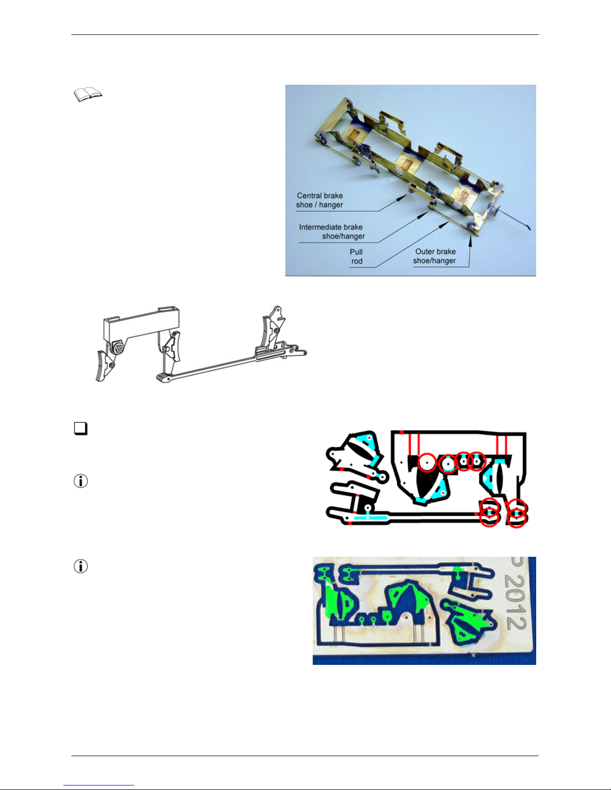
Class 47 Brake Detail
These instructions are for kits
with the etched brake
components etch F005. They describe
the assembly of the brake gear for one
half-side of a bogie; there are eight
such assemblies in all, four of each
hand.
Using a 0.35mm drill in a hand pin-vice,
drill through the holes in the etch as
indicated by the red rings in the drawing.
To help prevent distortion, press the
components against a hard surfac e with
a fine sc rewdriver while drilling.
There is fine detail in the etc h which
can easily become obscured by solder.
It is perhaps as well to tin all c omponents
with a thin film of solder now, to avoid
bringing excess solder on the iron to the
components when assembling.
Class 47 Brake Detail 38/52
(c) PenBits Model Railways, All Rights Reserved 04/05/2017
Page 39
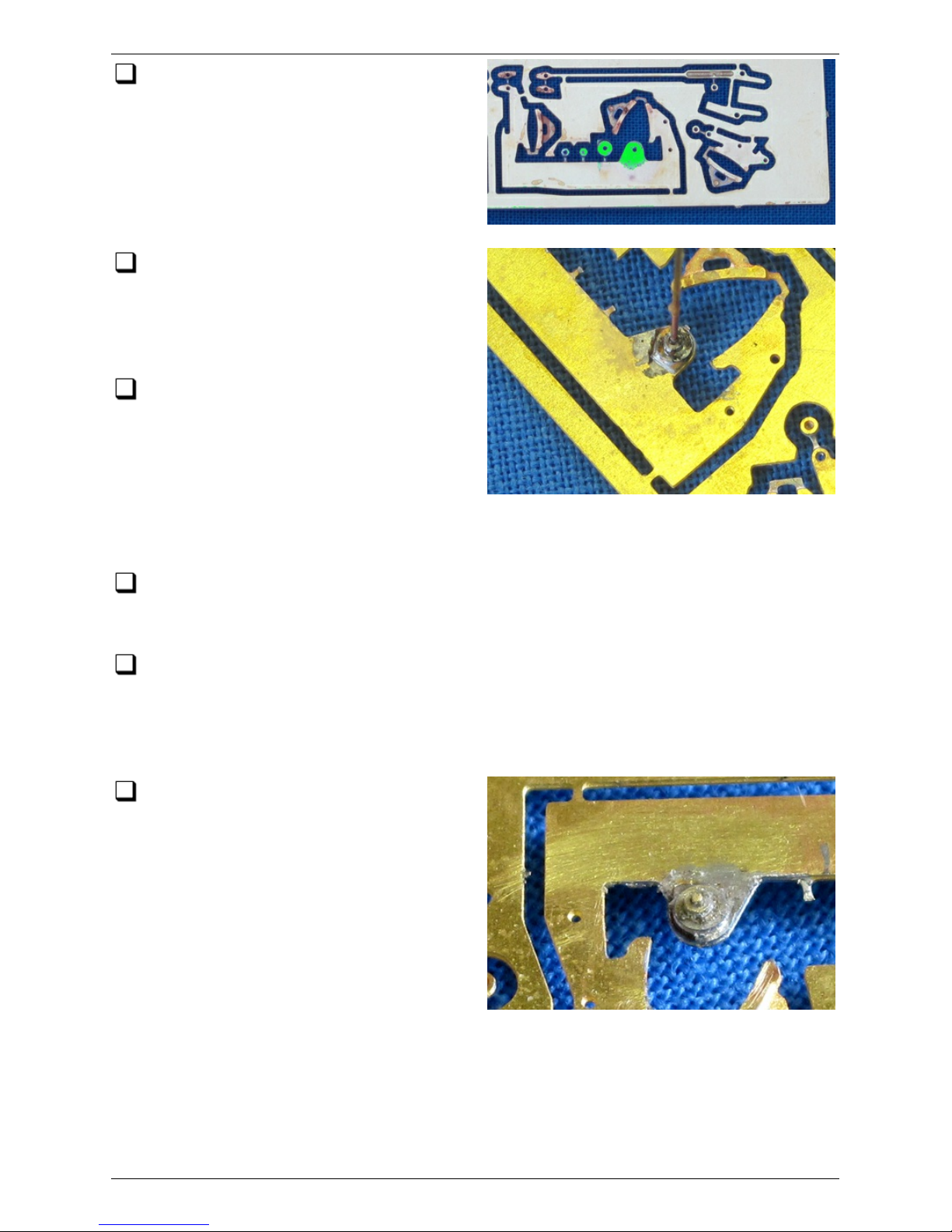
Tin the areas shown shaded green. Run
through the holes with the drill again
after tinning.
Place the fret on to a hard working
surface suc h that the tags, holding the
nut and crank detail to the plank joining the
centre and intermediate brake levers, are
with their backs flush to the surface.
Take a length of the 0.3mm wire and
apply some paste flux to its end 2mm or
so. Insert the wire into the hole in one of
the nuts (a spare is provided in case of
losses). Working against the hard surface,
and keeping the end of the wire inside the
hole, cut the nut from its tag, as closely to the side of the nut and as c leanly as you
can.
The paste flux should retain the nut on the wire while you now lift the nut onto the
crank detail and push the wire into the hole in the crank. Cut the c rank from its
tag, again using the wire to retain c ontrol of it.
Now lift the nut and crank detail, still retained on the wire by the paste flux, onto
the bracket extending downwards from the plank, and locate the end of the wire
into the hole in the bracket. Slide the c rank detail and nut down the wire so that all
three components are flush to each other, rotate the crank around the wire until its
flat edge is parallel with the long edges of the plank, and solder up.
Trim and c lean up the ends of the wire;
flush to the bac k of the bracket, and
with a little protruding from the front of the
nut to represent the end of the c rank pivot
bolt.
Class 47 Brake Detail 39/52
(c) PenBits Model Railways, All Rights Reserved 04/05/2017
Page 40
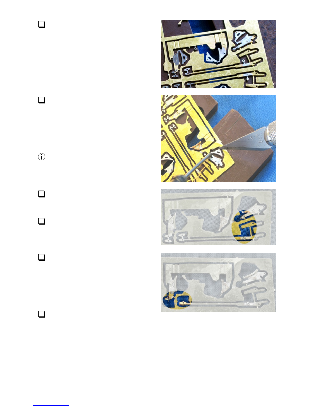
Invert the fret and support it between
two blocks, or over a recess, to
accommodate the crank detail now on the
reverse side.
Make the 180° folds in the tags to turn
the three brake shoe detail etc hes over
on to their backing plates. Apply some flux,
hold the folds shut and sweat the shoe
components together, perhaps with just a
tiny amount of extra solder applied to the
curved fac e of each shoe.
Use knife blades or small sc rewdrivers to
define the c entres of the 180° folds and
to drive each one over.
Fold over, 180°, and solder up the boss
at the lower end of the outer brake
lever.
Fold over, 180°, and solder up the boss
towards the outer end of the pull rod.
Fold over, 180° the boss at the lower
end of the intermediate brake lever.
Pass a length of 0.3mm wire through the
hole in the boss, using the wire to align the
two parts. Solder in t he wire. Finish it flush
with the rear of the boss, and projecting
about 1mm from the front.
Fold over, 180°, the boss at the inner
end of the pull rod. Do NOT solder here at this stage.
Class 47 Brake Detail 40/52
(c) PenBits Model Railways, All Rights Reserved 04/05/2017
Page 41
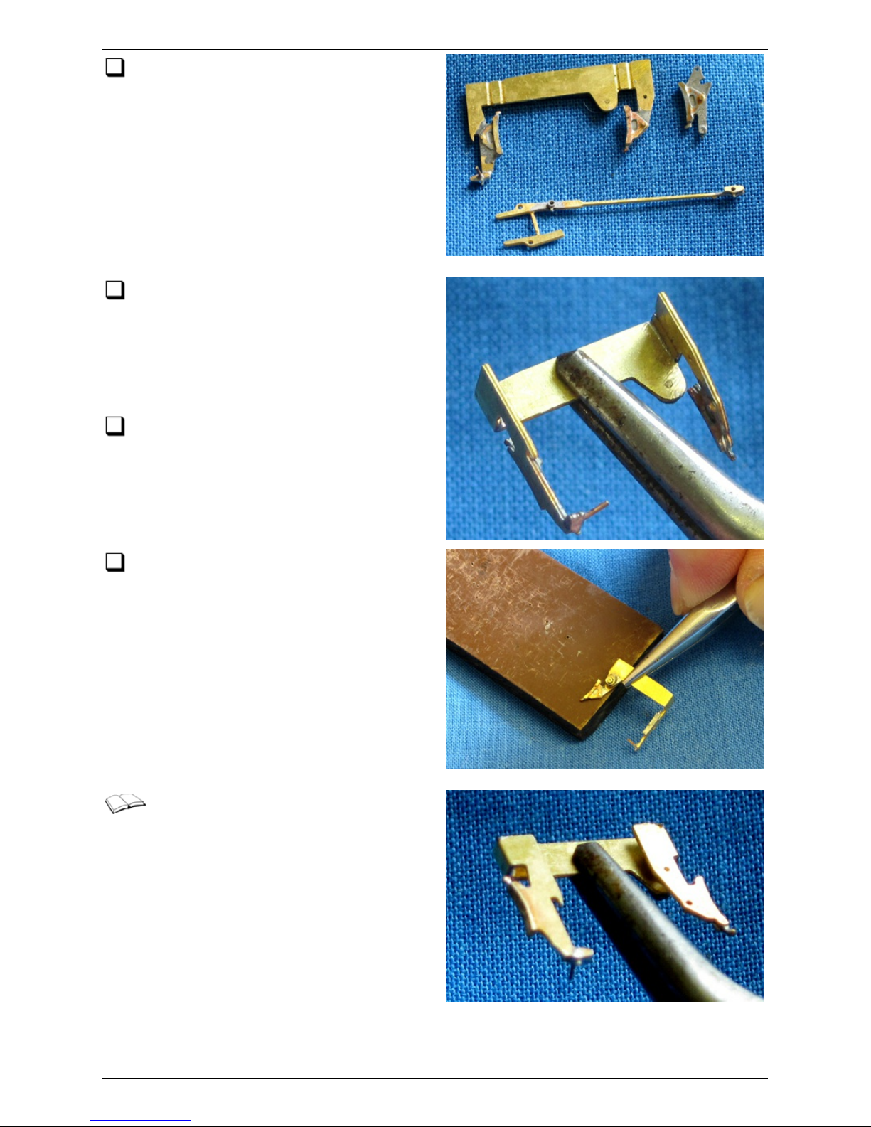
Remove the three detail etches from
the fret and clean off remnants of the
etched tags. The folding tags on the brake
shoes are best left for now, as they
prevent the shoe details from coming adrift
during subsequent soldering operations.
Taking the intermediate/central brake
shoes etch, make the two innermost
folds on the plank joining the two brake
hangers and reinforce them with a small
amount of solder, taking care not to fill the
adjacent fold lines.
Using a file, smooth the lower inside
edge of the plank, leaving it with a
slight chamfer. This is to guard against any
possibility of the secondary spring detail,
fitted to the bolster, 'picking up' on that
edge.
Make the two remaining folds in the
plank to turn it back on itself, and
reinforce them with solder also.
This is how the inside of the
intermediate/central brake shoes
etch looks when folding is complete. All the
detail features are now facing outwards,
the same way.
Class 47 Brake Detail 41/52
(c) PenBits Model Railways, All Rights Reserved 04/05/2017
Page 42
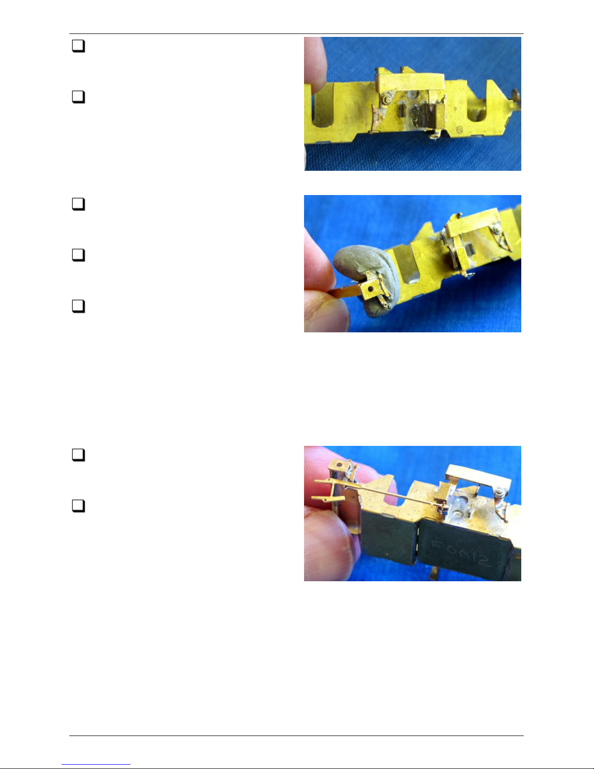
Taking one of the bogie subframe
assemblies, make the folds at the ends
of each of the subframe's outriggers.
Make the slotted halving joint between
the intermediate/central brake shoes
etch and the top of one of the two
outriggers which match the handing of the
e t c h. Support the etch in t he correct
position, with a lump of 'Blu-tak' perhaps,
and solder up the joint.
Similarly locate and fix the outer brake
shoe detail in the slot in the inside edge
of the bogie subframe end stretc her.
Remove the folded-over tags from the
ends of the brake shoe details.
Test fit the wheelsets to check that
there is sufficient clearance between
the brake shoes and the wheels over the
operating range of the suspension (the design static position of the wheelsets is with
t he tops of the bearing carrier ears level with the top of the subframe sides, with
dynamic deflections of ±0.5mm service, ±0.75mm max, from there).
Small adjustments can be made by judicious filing or bending of the detail parts. If you
find that you need to adjust the outriggers, remember to c hec k that the fit of the
Bolster, between the outriggers, is maintained.
Thread the plain end of the pull rod over
the wire at the base of the intermediate
brake shoe hanger.
Line up the boss, on the inside of the
other end of the rod, with that at the
base of the outer brake shoe hanger and
solder them together.
Class 47 Brake Detail 42/52
(c) PenBits Model Railways, All Rights Reserved 04/05/2017
Page 43
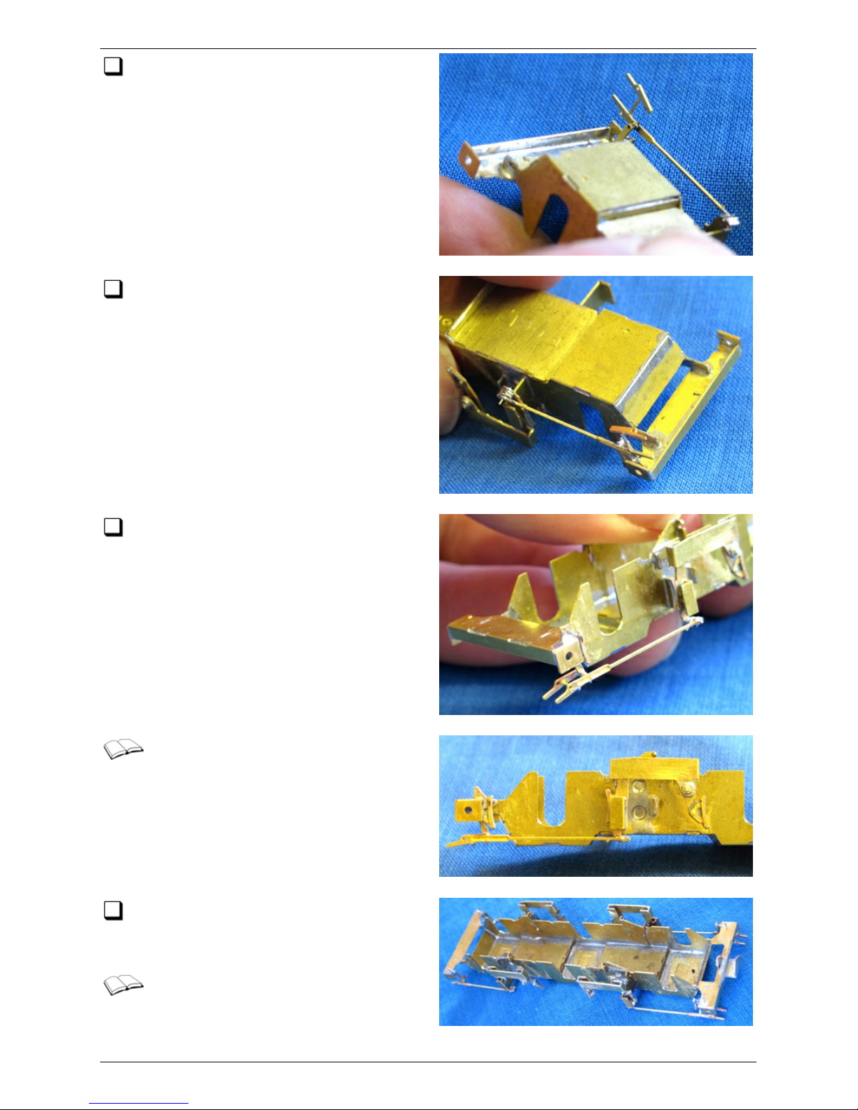
Solder up the plain end of the rod to
the intermediate hanger and trim off the
ends of the wire flush.
At the outer end of the pull rod, make
the first fold between the inner pull rod
end detail and its support, and reinforce
the fold with a touch of solder.
Make the fold at the other end of the
support to swing the inner pull rod up
into position. Reinforce the fold with a
touch of solder…
…and that's it… finished.
Repeat for the remaining sets of brake
gear. You may wish to take a welldeserved break first!
To c omplete the detailing, you may
wish to glue in place a suitable
representation of the actuator between the
inner and outer pull rods – the moulding
Class 47 Brake Detail 43/52
(c) PenBits Model Railways, All Rights Reserved 04/05/2017
Page 44

from discarded Bachmann brake gear does nic ely, otherwise small pieces of plastic
strip and rod, brought toget her with some filler, can do the job.
Finally, reassemble the wheelsets and bogie bolsters into the subframes, and c hec k
all clearances.
Class 47 Brake Detail 44/52
(c) PenBits Model Railways, All Rights Reserved 04/05/2017
Page 45
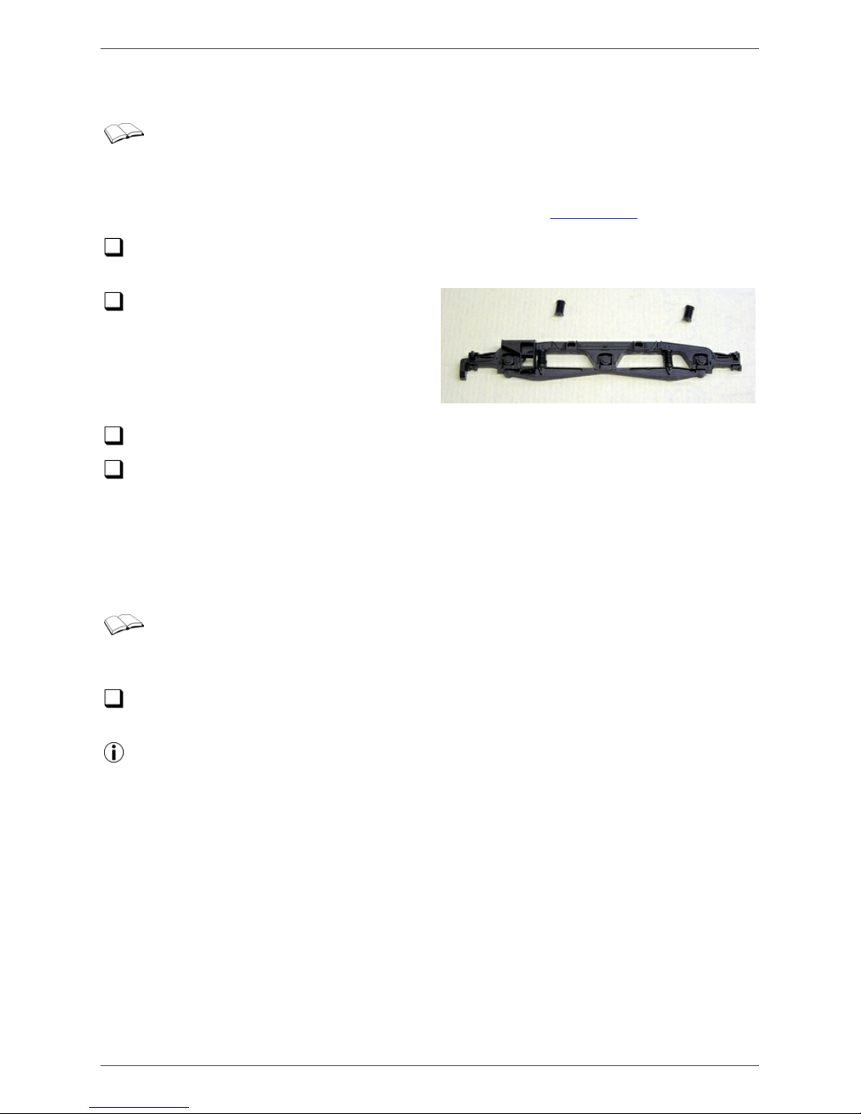
Class 47: Cosmetic Sideframes
This section deals with fitting either Bachmann sideframes with the etched brake
components or Heljan sideframes in any circumstances, for kits PK002, PK003,
PK004 and PK012, all using the subframe stretchers from etch F003. If you are fitting
the Bac hmann moulded bogie frames and brake gear for kit PK001, using the subframe
stretchers from fret F004, you should use instructions from this section instead.
Remove any detail and fixings from the rear of the sideframe to leave the inside
fac e of each sideframe moulding as a single flat plane surface.
Remove secondary spring detail from
the mouldings and put them safely to
one side. If you are fitting the etched brake
components, remove also the plastic brake
detail. The photo shows one of the Heljan
sideframes so treated.
Taking the etc hed bogie subframe, make the folds at the ends of the outriggers.
Offer up the sideframes to the subframe. The sideframes should fit flush to the
vertical faces of t he end stretc hers, the outriggers and, if fitted, the planks joining
the intermediate and c entre parts of the etched brake detail. You might make rebates
in the inside fac es of the sideframes to accommodate any discrepancies and to set
the desired overall width.
If you adjust the planks of the brake detail etc hes, be sure to re-check that the
bolsters will still pass inside them.
According to our drawings, the width of the prototype bogies, over the flat
outside surfac es of their main frames, excluding any pipework or c ast detail
features, scales out to 27.6mm.
Glue the plastic frame in place, against the vertical surfaces. Quick- set epoxy, or
Evo-stick, can be used.
To help get the cosmetic and etched frames parallel, clamp the etc hed subframe
to a flat surface and rest the lowest points of the plastic sideframes on the same
surface. Thin strips of appropriate thickness c an be used to set the precise height of
the sideframe relative to the subframe.
Class 47: Cosmetic Sideframes 45/52
(c) PenBits Model Railways, All Rights Reserved 04/05/2017
Page 46
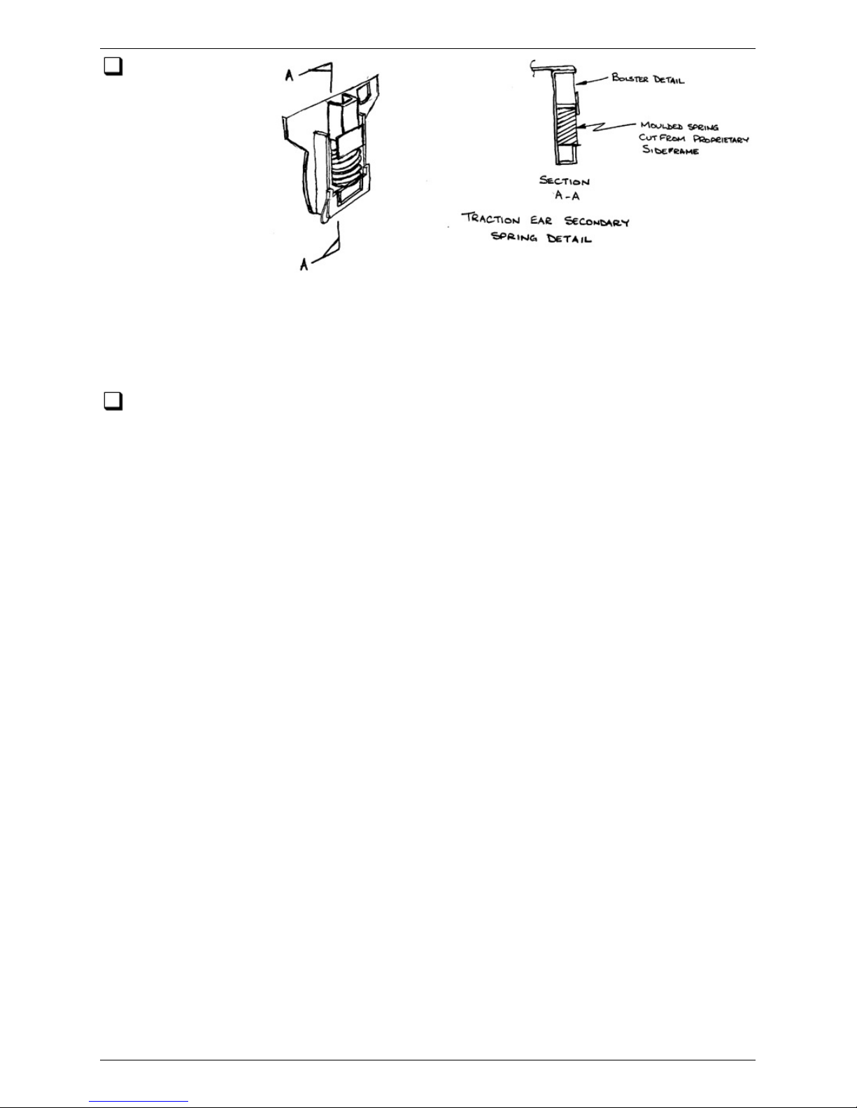
Take the etc hed
bolsters, bolster
detail etc hes and
the eight plastic
s e c o nd a r y springs
cut from the
sideframe
mouldings. Trim the
springs so that they
fit between the
secondary spring
hanger detail etc hes
and the bolster detail etc hes as shown. Fix the springs and bolster detail etches in
place on the traction ears using quick-set epoxy. Make sure that the detail etches are
securely home in their slots, and that the half-etched 180° foldback is glued back flat
against the outer face of the detail.
Test-fit the bolster into the bogie frames to check clearances.
Class 47: Cosmetic Sideframes 46/52
(c) PenBits Model Railways, All Rights Reserved 04/05/2017
Page 47
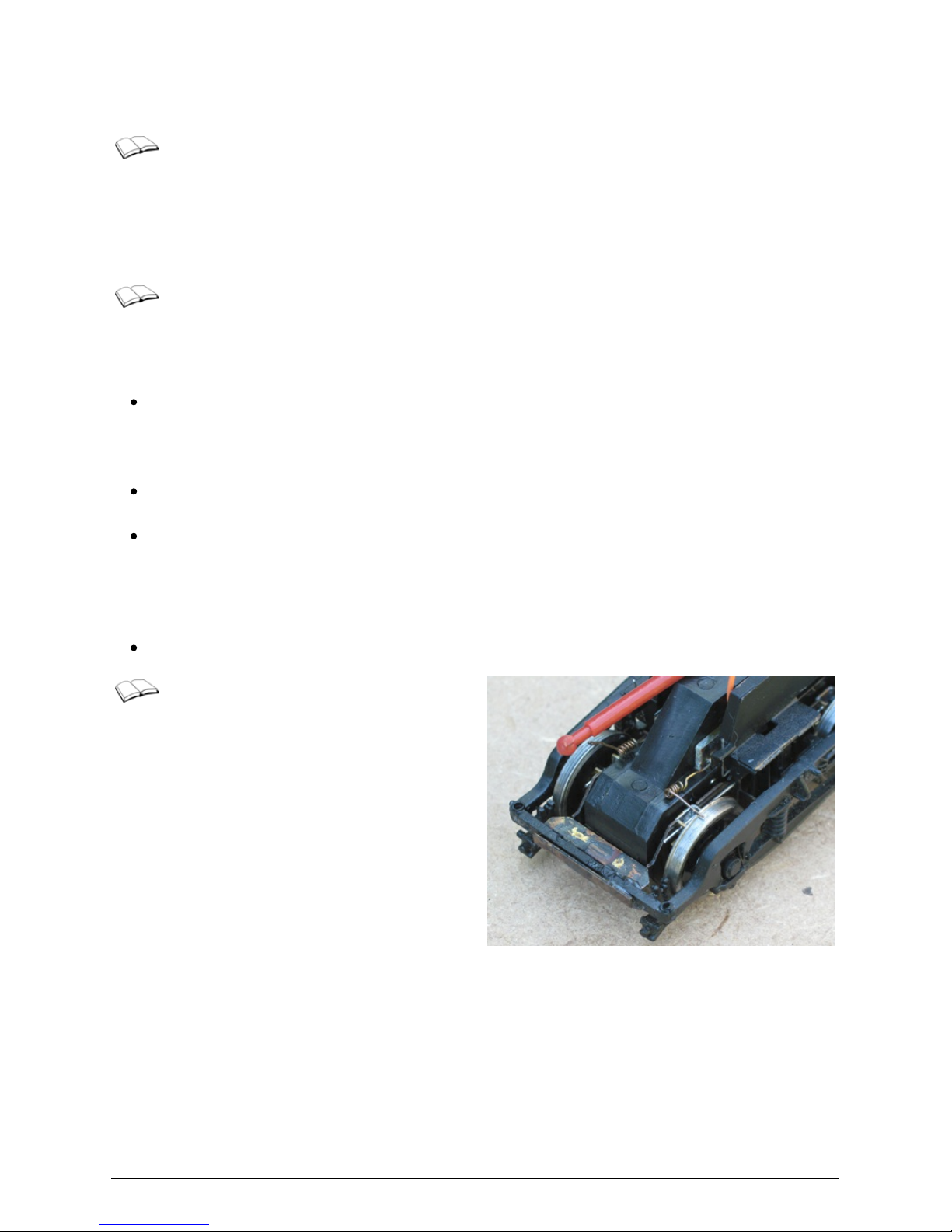
Pickups and Power
If you are using the 'Americ an' system of pickup, with the wheels on one side of
each bogie 'live' (i.e. with their wheelrims in electrical contact with the axles)
then there is no need to provide separate wire pickups; the electric al c onnection c an
be made simply to the securing sc rew at the top of the bolster. If, however, you are
using fully insulated wheelsets or, whilst using the 'American' system, still wish to add
pickups to the 'insulated' side of the bogie, we offer some guidelines below.
We suggest that pickups are mounted in some way on the drive train moulding
as there is very little movement bet ween that and the wheelsets. The pic kups
will not then interfere with the suspension. Various arrangements are possible and you
may already have your own preferences. Bear in mind the following:
If you fix any components to the sides of the drive unit moulding, make sure that
they do not interfere with the free movement of the drive unit within the bolster
and subframe. Limit their overall width to approximately that of the cover over the
worm drive.
If you run wires between the two articulated parts of the drive train, ensure that
they do not restrict the articulated movement.
Connecting wires should be sufficiently flexible, or routed in such a way, that they
transmit no forces arising from differential movements between the drive unit and
the bolster or loco chassis. If this condition is not met, there could be mechanical
'short circ uiting' of the suspension, with wobbles and shocks being transmitted
directly from the track to the loco body.
Connecting wires should be routed clear of the rotating drive shafts.
We have used phosphor bronze wire
pickups acting on the outer edges of
the flanges at the tops of the wheels. They
act on the outer wheelsets only, as there is
limited space to fit pickups to the centre
wheels.
Pickups and Power 47/52
(c) PenBits Model Railways, All Rights Reserved 04/05/2017
Page 48
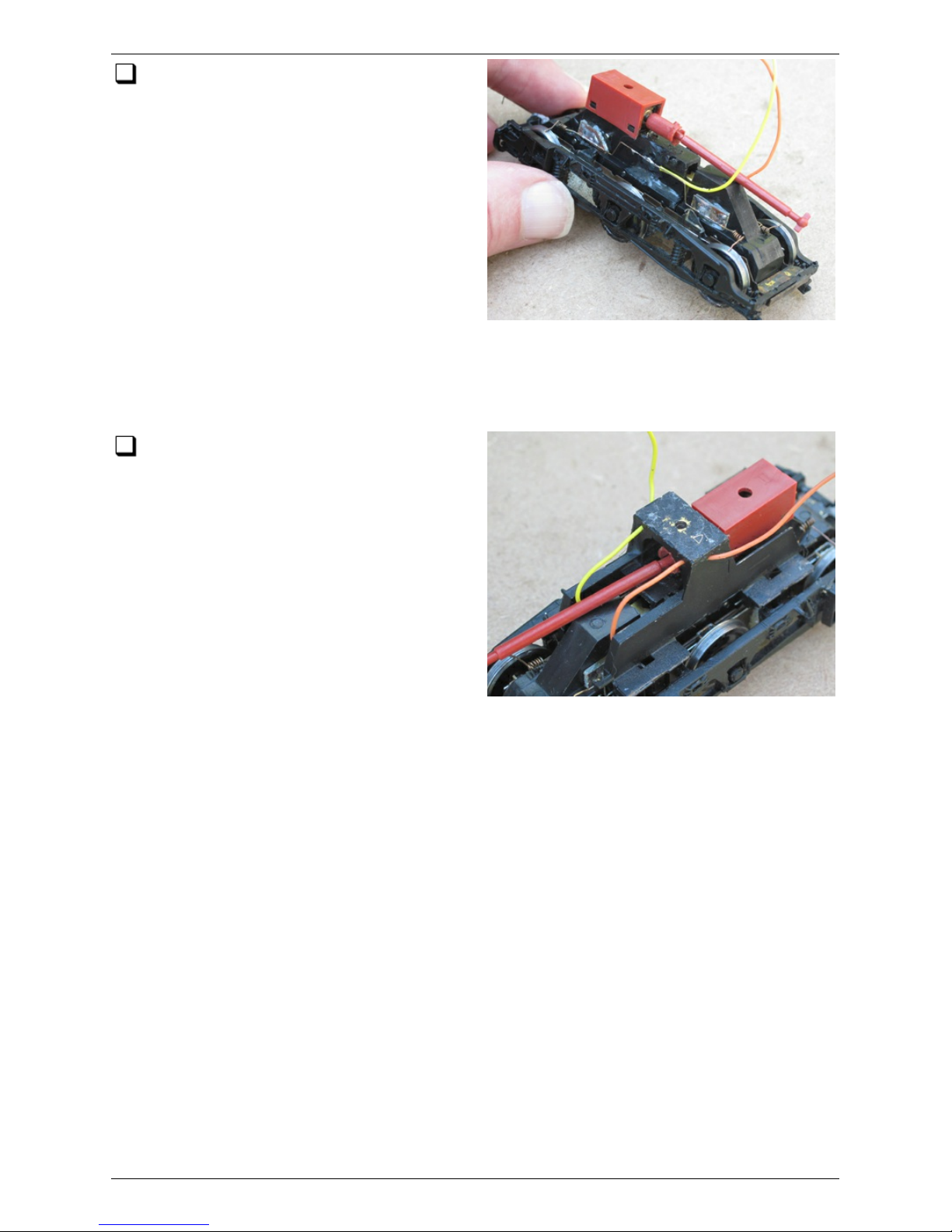
Small sections of pre-tinned copper-
clad PCB material are glued to the sides
of the drive unit. We use quick set epoxy,
thoroughly degrease the mating surfaces on
the drive unit and copper, and score the
surface of the drive unit to provide a key
for the adhesive. Pickups are bent up from
0.011" phosphor bronze wire as shown. The
trapezoidal bends allow the wire to flex as
the two parts of the drive unit articulate.
The wire coils are formed of six turns
around the shank of a 0.7mm drill, finished
so that the pick ups themselves are
preloaded below their operating position by about 1mm. The wires are tinned and then
soldered to the c opper-clad with a touch of the iron, with the feed wires tinned and
soldered on in turn, resin-c ored solder being used throughout.
The feed wires from the pickups back to
the loco PCB are firmly anchored to the
bogie bolsters; holes are provided near the
top of each bolster to assist. This allows
the route of the wires between the bolster
and drive unit to be set and then to remain
undisturbed when the wires are routed
through the chassis block during the fitting
of the bogie to the loco.
Pickups and Power 48/52
(c) PenBits Model Railways, All Rights Reserved 04/05/2017
Page 49
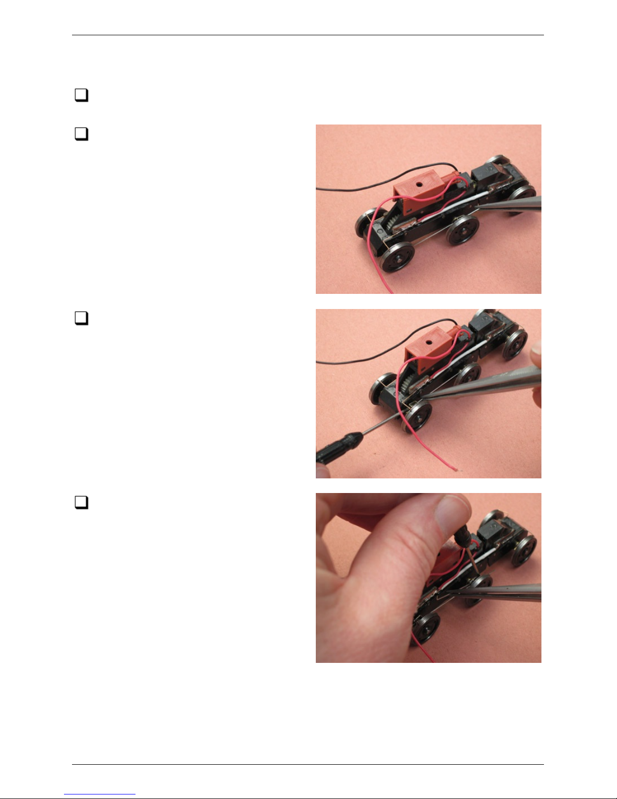
Final Assembly
Take one of the drive trains and fit its wheelsets into position. If you are using a
Heljan drive unit, replace the undertray.
Using a pair of tweezers to handle the
springs, and a small screwdriver to
manipulate the bearing carriers, thread one
of the primary springs through one of the
holes in the ears of the central bearing
carrier.
Thread the spring through the slots in
the ears of the bearing c arrier of the
outer axle.
Thread a second spring through the
hole in the other ear of the central
bearing carrier.
Final Assembly 49/52
(c) PenBits Model Railways, All Rights Reserved 04/05/2017
Page 50
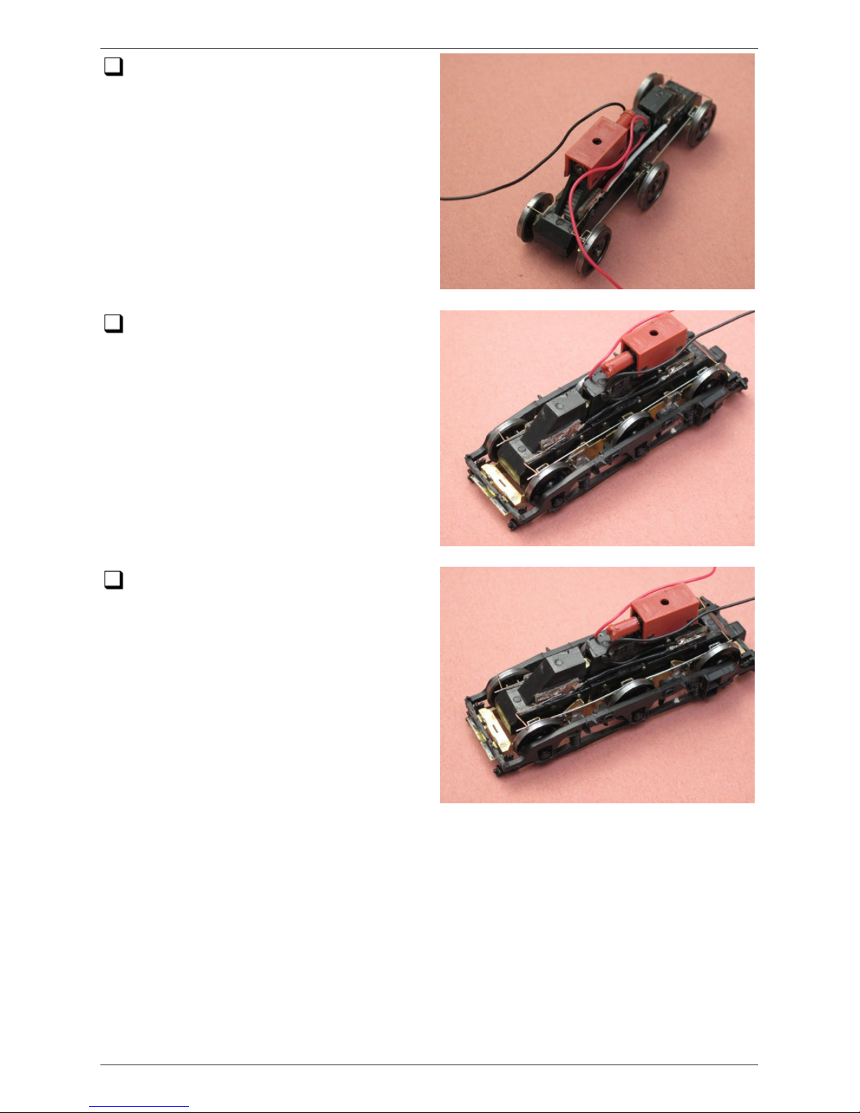
Thread that spring through the slots in
the ears of the bearing c arrier of the
other outer axle. Similarly fit the two
springs on the other side of the bogie.
Slot the drive train into the subframe
with the four primary springs resting on
the tops of the secondary spring seats.
Ensure that all six bearing carriers are
correctly engaged in the slots in the
subframe, and that the drive train is the
right way round (worm end towards the
coupling end of the bogie).
Use a screwdriver to spring the springs
outwards and downwards on to the
outer faces of the sec ondary suspension
seats.
Final Assembly 50/52
(c) PenBits Model Railways, All Rights Reserved 04/05/2017
Page 51
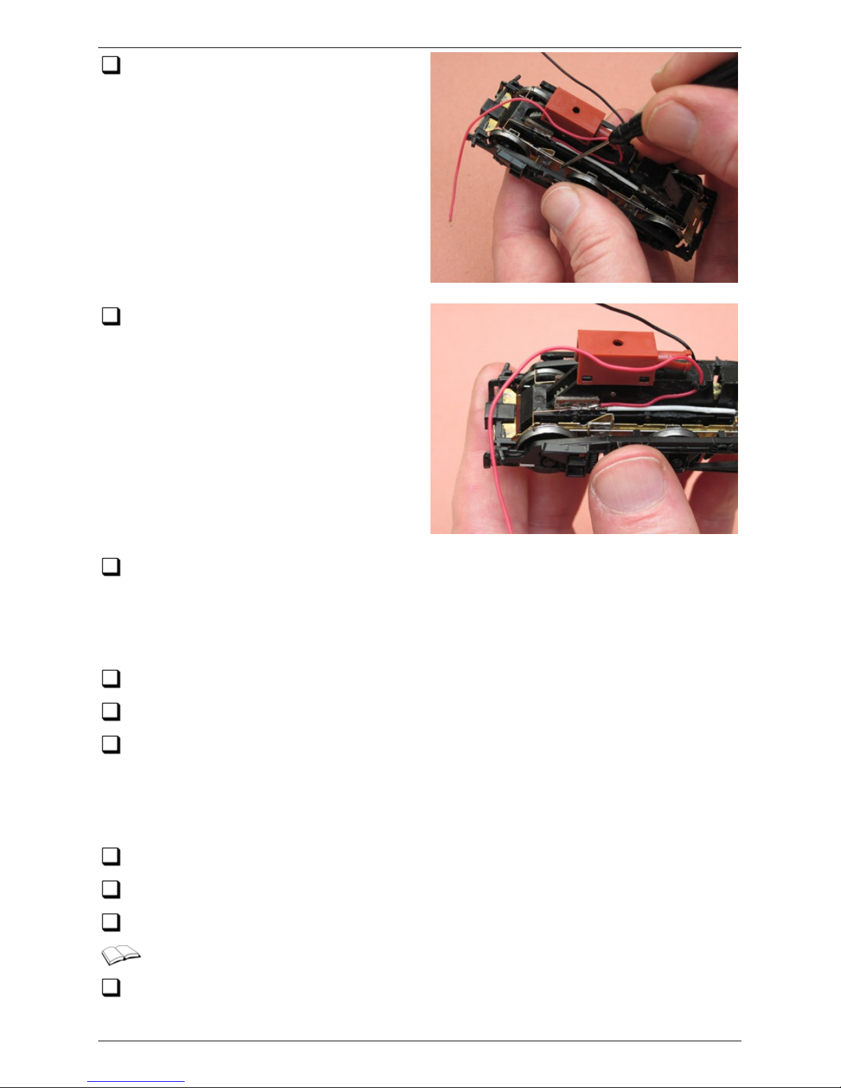
Push the springs downwards so that
they slide over the sec ondary and then
the primary suspension seats …
…until finally they clip into place under
the primary suspension seats.
Now take the bolster and slide it into place over the subframe. You should find that
the sec ondary springs on one side will snap in to place in their spring seats. On the
other side, working through the slots in the tops of the traction ears with a small flat
bladed screwdriver, push the secondary springs outwards and slide them down over
their spring seats until they also snap into place.
Find the cardan shaft and c lip the correct end into the drive soc ket of the bogie.
Remove the retaining sc rew and sleeve from the top pivot of the bogie.
Identify the c orrect end of the loco's c hassis block. Route the pickup wires through
the appropriate holes or slots in the block. Engage the free end of the cardan shaft
into the loco's flywheel drive soc ket and line up the bogie t op pivot with its pivot hole.
Take up any slack in the pick up wires. Fit the bogie retaining screw, sleeve and
washer.
Repeat all of the above for the other bogie.
Connect the pickup wires to the c orrect terminals of the loco's PCB.
Place the locomotive on some track and give it a test run under power.
All being well, thats it! - the modifications are complete.
Run the locomotive in gently at first. If the loco does not run freely or begins to
bind up at any point, pay particular attention to lubric ation of the axle bearings.
You can feel for any binding by rotating the wheel rims with the fingers - there is
Final Assembly 51/52
(c) PenBits Model Railways, All Rights Reserved 04/05/2017
Page 52

enough slack in the drive train gears that you should be able to distinguish between a
binding and a free wheelset.
Finally, replace the body of the locomotive according to the manufacturers'
instructions. On the Bachmann loco, you'll find that you'll need a slim-shafted c ross
headed sc rewdriver to replace the four screws adjacent to the bogies.
IMPORTANT NOTE: If you need to remove the body subsequently, please DO NOT at
any stage attempt to pull the chassis from the loco by pulling on the bogies, as this
may damage the secondary spring mountings.
Final Assembly 52/52
(c) PenBits Model Railways, All Rights Reserved 04/05/2017
 Loading...