

Page 1

PENBERTHY SERIES LC FLAT GLASS GAGES
INSTALLATION, OPERATION AND MAINTENANCE INSTRUCTIONS
Before installation these instructions must be read fully and understood
TABLE OF CONTENTS
Product warranty ................................................ 1
1. About the manual .......................................... 2
2. Introduction ................................................... 2
2.1 System description ................................. 2
3. Available models ........................................... 3
3.1 Design ratings at maximum and
minimum operating temperatures ....... 3
4. Inspection ...................................................... 4
4.1 Glass inspection ..................................... 4
4.2 User rating inspection............................ 4
5. Installation ..................................................4-5
5.1 Piping strain ............................................ 4
5.2 Differential thermal expansion.............. 4
5.3 Mirror viewing ......................................... 4
5.4 Nut retorquing ........................................ 5
5.5 Belleville washers (optional) ................. 5
6. Operation ....................................................5-6
6.1 Hydrostatic test ...................................... 6
7. Maintenance ...............................................6-7
7.1 Maintenance procedures ....................... 6
7.2 Troubleshooting ..................................... 7
8. Removal - disassembly - reassembly ......7-9
8.1 Disassembly ........................................... 7
8.2 Inspection of glass seating surfaces .... 8
8.3 Reassembly ............................................ 8
9. Disposal at end of useful life ........................ 9
10. Telephone assistance ................................... 9
11. Exploded parts diagrams ............................ 10
Tables and figures
Table 1 Design ratings of RLC gage ............... 3
Table 2 Design ratings of TLC gage ............... 3
Table 3 Bolt torque values .............................. 5
Figure 1 Nut tightening sequence ................... 5
Figure 2 Belleville washer position.................. 5
Figure 3 Gage disassembly .............................. 7
Figure 4 Nut loosening sequence .................... 7
Figure 5 Gage reassembly ............................... 8
Figure 6 Exploded parts diagram of
reflex gage ........................................ 10
Figure 7 Exploded parts diagram of
transparent gage .............................. 10
Product warranty
Emerson warrants its Penberthy products
as designed and manufactured to be free
of defects in the material and workmanship
for a period of one year after the date of
installation or eighteen months after the date
of manufacture, whichever is earliest. Emerson
will, at its option, replace or repair any products
which fail during the warranty period due to
defective material or workmanship.
Prior to submitting any claim for warranty
service, the owner must submit proof of
purchase to Emerson and obtain written
authorization to return the product. Thereafter,
the product shall be returned to Emerson with
freight paid.
This warranty shall not apply if the product has
been disassembled, tampered with, repaired or
otherwise altered outside of Emerson's factory,
or if it has been subject to misuse, neglect or
accident.
The responsibility of Emerson hereunder is
limited to repairing or replacing the product
at its expense. Emerson shall not be liable
for loss, damage or expenses related directly
or indirectly to the installation or use of
its products, or from any other cause or
for consequential damages. It is expressly
understood that Emerson is not responsible
for damage or injury caused to other products,
buildings, personnel or property, by reason of
the installation or use of its products.
This is Emerson’s sole warranty and in lieu of
all other warranties, expressed or implied which
are hereby excluded, including in particular all
warranties of merchantability or fitness for a
particular purpose.
This document and the warranty contained
herein may not be modified and no other
warranty, expressed or implied, shall be made
by or on behalf of Emerson unless made in
writing and signed by the company's general
manager or director of engineering.
valves.emerson.com © 2017 Emerson. All rights reserved. VCIOM-04074-EN 17/05
Page 2

PENBERTHY SERIES LC FLAT GLASS GAGES
INSTALLATION, OPERATION AND MAINTENANCE INSTRUCTIONS
1 ABOUT THE MANUAL
This manual has been prepared as an aid and
guide for personnel involved in installation or
maintenance. All instructions must be read and
understood thoroughly before attempting any
installation, operation or maintenance.
SAFETY INSTRUCTIONS
Emerson does not have any control over the
manner in which its liquid level gage is handled,
installed or used and Emerson cannot and does
not warrant or guarantee that a liquid level gage
is suitable for or compatible with the user's
specific application.
WARNING
Contained fluids may be pressurized and can exit
vessel connections unexpectedly due to apparatus
or material failure. Safety glasses should be worn
when installing a liquid level gage. Failure to
follow instructions could result inserious physical
injury or property damage.
2 INTRODUCTION
Penberthy liquid level gages are used to allow
direct visualization of liquid level in vessels.
By peering through the glass, it is possible to
monitor color, clarity and level of a gas/liquid
interface. Gages are available in varying lengths
and configurations (end connect, side connect,
multiple sections, NPT or flange connections,
etc.). Visual indication can be enhanced by
using reflex glass or illuminators (accessory).
2.1 System description
Penberthy Series LC gages comprise six
basic components. Each component may vary
slightly, depending on the desired physical and
mechanical properties for the gage. Use the
exploded parts views in Section 11 as additional
reference material.
Chamber: provides a pressure-retaining
metallic channel for the liquid to enter and be
viewed. Slot(s) are machined into the chamber
to provide direct visualization of the process
fluid.
Gaskets: seal the gap and prevent leakage
between the chamber and the glass. Gaskets
are available in a variety of materials for
compatibility with the media in the gage.
Glass: allows for visual observation of the
process fluid in the chamber.
Cushion: acts as a protective buffer between
the glass and the cover. For proper sealing,
cushions must be as hard or harder than the
gasket material.
Cover: protects the glass assembly from
external hits and provides a flat, rigid surface
that is used to compress the gage assembly
evenly. The large chamber gage cover
resembles a football. It has significantly more
metal along the center of the sides to provide
more strength and resistance to high pressure
stresses.
Bolting: compresses the components between
the covers (transparent gages) or cover and
chamber (reflex gages).
Shield: (optional on transparent gages) used
to prevent the process media from contacting
the glass.
2
Page 3

PENBERTHY SERIES LC FLAT GLASS GAGES
INSTALLATION, OPERATION AND MAINTENANCE INSTRUCTIONS
3 AVAILABLE MODELS
Penberthy large chamber (Series LC) liquid level gages are designed for applications other than
steam/water. Penberthy SeriesLC liquid level gages are designed for service where the liquid
being gaged tends to boil or surge making reading difficult. The large liquid chamber tends to
minimize the effects of boiling and surging, thereby increasing the accuracy of the liquid level
readings.
3.1 Design ratings at maximum and minimum operating temperatures
TABLE 1
Gasket
material
®
(standard) or non-asbestos 4-9 2400 psig (16550 kPa) at -20°F (-29°C) to 100°F (38°C) 1840 psig (12690 kPa) at 600°F (316°C)
Grafoil
Top-chem 2000
25% glass filled PTFE 4-9 650 psig ( 4480 kPa) at -20°F (-29°C) to 100°F (38°C) 150 psig ( 1030 kPa) at 500°F (260°C)
NBR (Buna-N) 4-9 300 psig ( 2070 kPa) at -20°F (-29°C) to 100°F (38°C) 225 psig ( 1550 kPa) at 250°F (121°C)
FKM (Viton
PTFE (Teflon®) 4-9 300 psig ( 2070 kPa) at -20°F (-29°C) to 100°F (38°C) 150 psig ( 1030 kPa) at 500°F (260°C)
®
®
) 4-9 300 psig ( 2070 kPa) at -20°F (-29°C) to 100°F (38°C) 180 psig ( 1240 kPa) at 400°F (204°C)
TABLE 2
Gasket
material
®
(standard) or non-asbestos 4-9 1580 psig (10890 kPa) at -20°F (-29°C) to 100°F (38°C) 1220 psig (8410 kPa) at 600°F (316°C)
Grafoil
Top-chem 2000
25% glass filled PTFE 4-9 650 psig ( 4480 kPa) at -20°F (-29°C) to 100°F (38°C) 150 psig ( 1030 kPa) at 500°F (260°C)
NBR (Buna-N) 4-9 300 psig ( 2070 kPa) at -20°F (-29°C) to 100°F (38°C) 225 psig ( 1550 kPa) at 250°F (121°C)
FKM (Viton
PTFE (Teflon®) 4-9 300 psig ( 2070 kPa) at -20°F (-29°C) to 100°F (38°C) 150 psig ( 1030 kPa) at 500°F (260°C)
PCTFE/(Kel-F®) shields 0.063"
(1.6 mm) thick
®
®
) 4-9 300 psig ( 2070 kPa) at -20°F (-29°C) to 100°F (38°C) 180 psig ( 1240 kPa) at 400°F (204°C)
Glass
size
4-9 2400 psig (16550 kPa) at -20°F (-29°C) to 100°F (38°C) 100 psig ( 690 kPa) at 500°F (260°C)
Glass
size
4-9 1580 psig (10890 kPa) at -20°F (-29°C) to 100°F (38°C) 100 psig ( 690 kPa) at 500°F (260°C)
4-9 300 psig ( 2070 kPa) at -20°F (-29°C) to 100°F (38°C) 180 psig ( 1240 kPa) at 400°F (204°C)
Wetted parts material steel or stainless steel w/B7 bolting
Wetted parts material steel or stainless steel w/B7 bolting
Model RLC reflex
Model TLC transparent
Note: lower temperatures are possible with metallic material variation. (e.g., 316 stainless
construction, Grafoil
®
gaskets/cushions useable to –325°F (-198°C)).
The pressure and temperature ratings may deviate from the previous tables if the gasketing
materials of construction and/or bolting are other than those specified. Higher and/or lower
temperature ratings are available with different materials of construction.
To determine the maximum allowable working pressure for a specific temperature within the
design limits stated in the tables, the user should refer to applicable technical data sheets or,
when provided, the specifically stated design limits on a product proposal.
Note: under no circumstances should shields be used in reflex style gages. Installation of shields
in reflex style gages will keep the liquid from coming in contact with the refractive prisms, thereby
prohibiting visualization of the liquid level in the gage.
DANGER
NEVER exceed these design ratings or application data. Exceeding design ratings or application data
may result in mechanical failure of gage components resulting in death, serious personal injury and
property damage.
NOTES
Grafoil® is a registered trademark of Graftech.
Top Chem 2000® is a registered trademark of Klinger.
PCTFE (formerly known as Kel-F® - a registered trademark of 3M) is manufactured by Daikin.
Viton® and Teflon® are registered trademarks of E.I. duPont de Nemours and Company.
3
Page 4

PENBERTHY SERIES LC FLAT GLASS GAGES
INSTALLATION, OPERATION AND MAINTENANCE INSTRUCTIONS
4 INSPECTION
On receipt of a liquid level gage, check all
components carefully for damage incurred in
shipping. If damage is evident or suspected,
do not attempt installation. Notify the carrier
immediately and request a damage inspection.
Standard Penberthy 1 section TLC gage
consists of: (1) chamber, (2) gaskets, (2)
borosilicate flat glass, (2) rubber bands, (2)
cushions, (2) covers, (1) washer, (1) nameplate
and (8-14) bolting sets, depending on the size.
4.1 Glass inspection
The self stick caution tape was applied at the
factory to protect the glass during shipping,
handling and installation. Do not remove
the tape from the glass until all installation
procedures have been completed, except
during receiving inspection to inspect glass
momentarily for shipping damage. Glass that
is not protected will be vulnerable to dust, grit,
tools and any other objects which may scratch,
chip or break the glass.
WARNING
DO NOT use glass that is chipped or even slightly
scratched. Glass surface defects weaken the
glass, which may result in glass breakage and
fluid loss under pressure resulting in serious
personal injury or property damage.
4.2 User rating inspection
The user should confirm that:
1. The Series LC liquid level gage model
and assembly number stamped on the
nameplate conform to the description on
the user's purchase order.
2. The operating conditions described in
the purchase order agree with the actual
operating conditions at the installation site.
3. The actual operating conditions at the
installation site are within the application
data shown on the relevant technical data
sheet or product proposal referred to
previously.
4. The materials of construction of the
liquid level gage are compatible with both
the contained media and surrounding
atmosphere in the specific application.
SAFETY INSTRUCTIONS
If the size, model or performance data of the
liquid level gage as received does not conform
with any of the criteria above, do not proceed with
installation. Contact an authorized Penberthy
distributor for assistance. The incorrect gage can
result in unacceptable performance and potential
damage to the gage.
5 INSTALLATION
Installation should only be undertaken by
qualified, experienced personnel who are
familiar with equipment of this type. They
should have read and understood all of the
instructions in this manual. The user should
refer to relevant technical data sheets or
product proposal to obtain dimensional
information for the specific size and model
liquid level gage.
All liquid level gage installations should be
provided with gagecock sets equipped with a
ball check shut-off. Gagecock sets are designed
to isolate the gages from the pressure vessel
when it becomes necessary to drain or service
the gages. The ball check shut-off is designed
to retard leakage of the contained fluid in the
event of gage glass breakage. Ball checks are
available for both positive and negative vessel
pressures.
The number of different types of gage and
gagecock installations is too great to detail
adequately in an installation manual. Therefore,
it is the user's responsibility to ensure that
knowledgeable installation personnel plan and
carry out the installation in a safe manner.
The following procedures are some of the
installation guidelines that should be employed:
5.1 Piping strain
The gage should be mounted and connected
so that is does not support any piping weight.
Piping not supported properly, independent of
the gage, may subject the gage to stresses that
can cause leaks or glass breakage. Support
brackets are available as an accessory.
5.2 Differential thermal expansion
High mechanical loads may be imposed on a
gage by expanding and contracting pipes due
to hot or cold service. Such mechanical loads
on the gage must be minimized by the use of
expansion loops in the system. Failure to allow
for expansion or contraction can result in leaks
or glass breakage.
5.3 Mirror viewing
For added safety, a system of indirect viewing
by means of mirrors should be installed to
protect personnel from the hazards of possible
gage failure.
4
Page 5

PENBERTHY SERIES LC FLAT GLASS GAGES
INSTALLATION, OPERATION AND MAINTENANCE INSTRUCTIONS
5.4 Nut retorquing
Nut re-torque is vital to the operation of a liquid
level gage because gaskets take permanent
'set' under initial bolt loading at assembly.
Tightening of nuts before installation to values
specified in Table 3 is necessary to insure
pressure retaining capabilities of a liquid
level gage to specific design ratings. The user
must refer to the liquid level gage model and
assembly number and to the purchase order
or tag to determine materials of construction.
SAFETY INSTRUCTIONS
Before placing the liquid level gage into initial
operation, torque values must be verified. From
factory testing to installation, gasketing may take
'set' reducing closure force. Retorquing before
operation reduces chance of leakage or gasket
'blow out'.
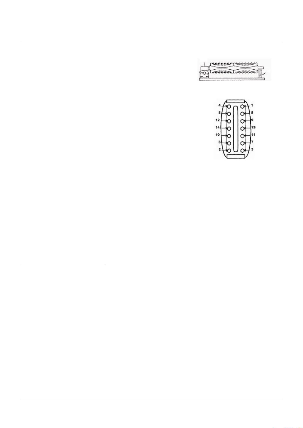
Using a torque wrench, tighten nuts in 5 ft·lb
(7Nm) increments following the 'Z' pattern
sequence in Figure 1, until the torque values
shown in Table 3 for the specific liquid level
gage are reached. For multiple section gages,
torque the center section(s) and progressively
work toward the ends of the gage.
If bolting, gasketing or glass on any repaired
section of a multi-section gage is disturbed,
all sections must be checked for integrity and
retorqued as necessary.
WARNING
Failure to comply with the proper torquing
sequence or force value can lead to leakage,
gasket blow-out or glass breakage resulting in
gage failure, serious personal injury or property
damage.
5.6 Belleville washers (optional)
Belleville washers are used to reduce the need
to retorque nuts. This is especially important
for gages subject to pressure and/or thermal
cycling. The conical washers allow for material
expansion and contraction while maintaining
axial bolt loading and, therefore, compression
on the gasket.
Model RLC gages require 7 washers per nut,
model TLC gages require 4 washers per nut
(8per bolt). Washers should be assembled with
the cupped side facing the gage cover. Refer to
Figure 2 for proper washer assembly.
Note: the following procedure is to be done on
only one side of a transparent gage.
Using a torque wrench, tighten nuts in 5 ft·lb
(7Nm) increments following the 'Z' pattern
sequence found in Figure 1 until the torque
values shown in Table 3 are reached.
6 OPERATION
Before initializing liquid level gage operation,
check that all installation procedures
have been completed. Use only qualified,
experienced personnel who are familiar with
liquid level gage equipment and understand
the implications of the tables and all the
instructions thoroughly. Check to determine
that all connections are pressure tight. Ensure
that nuts have been retorqued to their proper
values as specified in Table 3. Remove self stick
caution tape from the glass and inspect to be
sure that glass is clean and free of any damage
such as cracks, scratches, pits and chips.
FIGURE 1
Nut tightening sequence
FIGURE 2
Belleville washer position
Belleville
washer
Cover
Note: depending on gage size there may be
less bolting than shown in Figure 1. Start at the
center and follow the 'Z' pattern outward to the
limit of bolting on a specific gage.
TABLE 3 - BOLT TORQUE VALUES
Gasket material ft·lb (Nm)
RLC and TLC w/Grafoil
RLC and TLC w/non-asbestos (optional) 35 to 40 (48 to 54)
Top-chem 2000
PTFE and PCTFE (Kel-F®) 20 to 25 (27 to 34)
25% glass filled PTFE 19 to 22 (26 to 30)
All models with FKM (Viton®) or elastomeric (optional) 10 to 15 (14 to 20)
TLC with PCTFE (Kel-F®) shields (optional) 0.063" (1.6 mm) 20 to 25 (27 to 34)
®
(standard) 20 to 25 (27 to 34)
®
20 to 25 (27 to 34)
5
Page 6

PENBERTHY SERIES LC FLAT GLASS GAGES
INSTALLATION, OPERATION AND MAINTENANCE INSTRUCTIONS
6.1 Hydrostatic test
DANGER
Liquid level gage installations should be brought
into service slowly to avoid excessive shock or
stress on the glass. Rapid pressurization or
sudden changes in temperature may cause glass
breakage. To avoid excessive thermal shock
or mechanical stress on glass, the connecting
gagecocks should be opened slightly, and the
gage temperature and pressure allowed to slowly
equalize. If the gagecocks are equipped with ball
checks, the gagecocks must be opened all the
way after the pressure and temperature have
equalized to permit operation of the automatic
ball checks in the event of failure. Failure to
follow the recommended operating procedures
can result in death, severe personal injury and/or
property damage.
Take all precautions necessary to handle the
possibility of leakage during the test.
Hydrostatically pressure test all installations
to at least 100 psig (690 kPa) but less than
the design pressure and correct any leakage
beforeproceeding.
7 MAINTENANCE
WARNING
Use only qualified, experienced personnel who
are familiar with liquid level gage equipment and
understand the implications of the tables and
all the instructions thoroughly. DO NOT proceed
with any maintenance unless the liquid level gage
has been relieved of all pressure or vacuum, has
been allowed to reach ambient temperature and
has been drained or purged of all fluids. Failure
to follow instructions can cause serious personal
injury and property damage.
The rate at which components degrade
is dependent upon a variety of conditions.
Pressure, temperature and process media all
influence the rate at which gage components
deteriorate. Higher temperatures can
accelerate the deterioration of gaskets,
cushions, glass and metals. Acids and similar
chemicals can break down the integrity
of almost any material. Concentration of
chemicals can accelerate the corrosion rate.
Emerson cannot create a blanket maintenance
schedule for every application.
The end user is the most familiar with the
process media and conditions and must
be responsible for creating a maintenance
schedule. The user must create maintenance
schedules, safety manuals and inspection
details for each liquid level gage.
Realisticmaintenance schedules can only be
determined with full knowledge of the services
and application situations involved. These
will be based upon the user's own operating
experience with their specific application.
If bolting, gasketing or glass on any section of
a multi-section gage is disturbed, all sections
must be checked for integrity and retorqued or
repaired as necessary.
On all installations the following items should
be evaluated regularly by the user for purposes
of maintenance:
1. Glass, for cleanliness and signs of damage
or wear.
2. Shields, if used, for signs of clouding, wear
or deterioration.
3. Gage, for signs of leakage around gaskets
or at commections.
4. Gage, for signs of internal or external
corrosion.
7.1 Maintenance procedures
Glass should be given regular and careful
attention. Keep glass clean using a commercial
glass cleaner and a soft cloth. Inspect the
surface of the glass for any clouding, etching or
scratching or physical damage such as bruises,
checks or corrosion. Glass that is damaged
is weakened and may break under pressure.
Shining a light at approximately a 45° angle
will aid in detecting some of these conditions.
Typically, damaged areas will glisten more
brightly than the surrounding glass because
the light is reflected.
Detection of any damage, problem areas or
surface wear is sufficient evidence to take
the liquid level gage out of service. DO NOT
proceed with operation of the liquid level gage
until the glass has been replaced with a glass
replacement kit following the disassembly reassembly instructions in Section 8.
Shields showing any signs of clouding, wear
or deterioration are an indication that the
gage glass has been exposed, or could soon
be exposed to the contained fluid. Take liquid
level gage out of service immediately. DO NOT
proceed with operation of the liquid level gage
until shields and glass have been replaced
by following the disassembly-reassembly
instructions in Section 8.
Gasket leaks must be repaired immediately.
DO NOT proceed with operation of a liquid
level gage until gaskets have been replaced by
following Section 8 disassembly-reassembly
instructions.
6
Page 7
PENBERTHY SERIES LC FLAT GLASS GAGES
INSTALLATION, OPERATION AND MAINTENANCE INSTRUCTIONS
Connection leaks at a flanged or threaded
connection should be corrected by tightening
the bolting at the connection or by taking the
liquid level gage out of service and wrapping
the connection threads with PTFE tape on all
male pipe threads.
Corrosion may occur if the user has selected
an improper material for the liquid level gage
application. It is the responsibility of the user to
choose a material of construction compatible
with both the contained fluid and the
surrounding environment. If internal or external
corrosion is present, an investigation must be
performed by the user immediately. It may be
necessary to contact an authorized Penberthy
distributor to better determine the origin of the
corrosion.
7.2 Troubleshooting
Problem: Glass becomes etched or clouded
prematurely in service.
Cause: Fluid being handled is not
compatible with the glass or shields.
Solution: Replace the glass and install
shields which will not be affected
bycontained fluid.
Problem: Glass breaks continually in
service despite careful attention
tomaintenance procedures.
Cause: Thermal shock, hydraulic shock,
mechanical loads, exceeding design
ratings or a combination of these.
Solution: Check entire system to determine
possible sources of loads. Check
application to determine actual
operating conditions and contact an
authorized Penberthy distributor on
how to proceed.
8.1 Disassembly
Secure a workbench, equipped with a vise at
one end, longer than the liquid level gage and
sufficiently wide to lay out parts as they are
removed. Attach and tighten a nipple to each
end connection to serve as temporary means
of supporting the liquid level gage during
disassembly and reassembly.
1. Grip nipple on one end with vise and hold up
the other end with a 2 x 4 or suitable prop as
shown in Figure 3.
2. Hold gage firmly; loosen nuts starting
at both ends of each section and then
proceeding from both ends to the center
ofeach section as shown in Figure 4.
3. Nut loosening sequence
- Remove nuts, washer, belleville washers
(if any) and nameplate.
- Tap covers with rubber hammer as needed
to loosen and remove.
- For belleville washer assemblies:
to remove covers, studs may need to be
removed by laying the assembly on its side
and knocking the stud/U-bolts through the
cover with a hammer and punch.
- Remove cushions, glass, shields (if any)
and gaskets.
- Tap liquid chamber or remaining covers as
necessary with rubber hammer to break
loose and remove remaining components.
- Remove, destroy and dispose of all glass,
cushions, gaskets and shields. Under no
circumstances should these components
be re-used or installed on a gage.
Note: if size of gage is smaller than shown,
follow spiraling sequence from the ends until
all bolting is loosened.
FIGURE 3
Vise
Prop
FIGURE 4
Nut loosening sequence
8 REMOVAL - DISASSEMBLY - REASSEMBLY
WARNING
Use only qualified, experienced personnel who
are familiar with liquid level gage equipment and
understand the implications of the tables and
all the instructions thoroughly. DO NOT proceed
with any maintenance unless the liquid level gage
has been relieved of all pressure or vacuum, has
been allowed to reach ambient temperature and
has been drained or purged of all fluids. Failure
to follow instructions can cause serious personal
injury and property damage.
WARNING
Once used, cushions, gaskets and shields are
deformed permanently by compression and, if
re-used, may cause leaks and high stress points
resulting in glass breakage. Glass may contain
hidden damage and internal stresses caused by
previous usage. If re-used, the glass may break
under pressure causing severe personal injury
or property damage.
7
Page 8

PENBERTHY SERIES LC FLAT GLASS GAGES
INSTALLATION, OPERATION AND MAINTENANCE INSTRUCTIONS
8.2 Inspection of glass seating surfaces
Clean the glass seating surfaces on the liquid
chamber and cover with a soft metal scraper
(preferably brass) to remove all burrs, rust and
remnants of the previous gaskets and cushions.
Exercise extreme care to avoid gouging or
scarring gasket and cushion seating surfaces.
Use a known flat piece of metal the same
approximate length as the glass or a new
piece of glass and a thickness gage to check
flatness of each glass seating surface on liquid
chamber and under cover. Surface must be flat
within 0.002 inch (0.05 mm). If any one surface
is found to be beyond a tolerance of 0.002 inch
(0.05 mm), the entire gage must be disposed
of and replaced. Gasket seating surface must
have a final surface finish of 62 to 250 AARH.
WARNING
Flatness of glass seating surfaces outside
0.002 inch (0.05 mm) tolerance specified is an
indication of the gage having been overstressed
through repeated exposure to mechanical,
thermal or hydraulic shock during its previous
service. Operation of a liquid level gage which
has been overstressed will result in abnormal
stresses on the glass which may cause glass to
break. If surface finish is not in the 62-250 AARH
range, gasket may extrude under pressure with
resulting sudden release of pressure, leakage
of contained fluid, serious personal injury or
property damage.
Glass seating surfaces should NOT be
machined to achieve seating tolerance. The
chamber and cover are designed for a critical
thickness to achieve the pressure/temperature
ratings. Machining glass seating surfaces may
result in non-compliance to the necessary
critical thickness due to material removal.
8.3 Reassembly
If all glass seating surfaces are found to be
within the 0.002 inch (0.05 mm) tolerance
described in the previous section, proceed to
obtain new glass, gaskets, cushions and shields
(if used) and proceed to reassemble as follows
(refer to exploded parts views in Section 11
ifneeded):
1. Clean threads on bolts and nuts to remove
all paint, rust and scale. Apply a light coat of
oil to the threads.
2. For transparent gages, measure distance
between bolt heads of each section and
cut a 1 x 4 piece of wood for each section
as shown in Figure 5. Insert studs through
holes in half the covers, thread nuts flush
with ends of studs and place covers on cut
1 x 4 pieces of wood along bench, side by
side, with liquid chamber. Use chamber to
space covers and line them up with vision
slots.
3. For reflex style and belleville reflex style
gages, grip nipple on one end of liquid
chamber with vise and hold up the other
end with a 2 x 4 or suitable prop as shown
in Figure 3. Lay out covers side by side
with liquid chamber. Slide all U-bolts on
chamber to their approximate location,
using covers to space U-bolts.
4. For transparent belleville style gages, insert
studs through holes in half the covers,
place four Belleville washers under nut with
pointed end toward the nut (see Figure 2),
thread nuts on stud and lay out covers on
cut 1 x 4 pieces of wood along bench, side
by side, with liquid chamber. Use chamber
to space covers and line them up with vision
slots.
5. Install rubber band around each piece
of glass and cushion, then place glass
centered inside each cover.
WARNING
Separate installation instructions are supplied
with replacement glass. All instructions supplied
with the glass must be followed, as there are
precautions to be taken when handling gage
glass. Among the precautions is avoidance of
bumping or sliding glass against any surface and
inspection of individual pieces. Failure to follow
any of the replacement gage glass installation
instructions could result in glass breakage with
resulting sudden release of pressure, severe
personal injury or property damage.
FIGURE 5
Block of wood
8
Page 9

PENBERTHY SERIES LC FLAT GLASS GAGES
INSTALLATION, OPERATION AND MAINTENANCE INSTRUCTIONS
6. Install shields, if used, and gasket on glass
being careful to keep components centered.
7. For transparent style gages, align studs
to accept liquid chamber and slide liquid
chamber into place being careful to keep
components centered.
8. For reflex style gages, install covers in place
while making sure alignment of components
is maintained with vision slot. Install
nameplate, washer and all nuts finger tight.
9. For reflex belleville style gages: install
nameplate and seven belleville washers
under each nut with pointed end toward the
nut (see Figure 2). Finger tighten nuts.
10. Using a torque wrench, tighten nuts in 5 ft·lb
(7 Nm) increments, following the sequence
in Figure 1 until the torque values shown in
Table 3 are reached.
Note: depending on gage size there may be
less bolting than shown in Figure 1. Start at
the center and follow 'Z' pattern outward to
the limit of bolting on a specific gage.
11. For transparent style gages, install
gaskets and shields, if used, centered
on vision slots.
12. Install rubber band around each piece
of glass and cushion, then place glass
centered on gasket or shields, if used.
13. Install covers in place being careful to
maintain components alignment inside.
14. Install nameplate, washer and nuts to
studs. Finger tighten nuts.
14A. For transparent belleville style gages:
install nameplate and four belleville
washers under each nut with pointed
end toward the nut (see Figure 2). Finger
tighten nuts.
Note: the following procedure is to be
done on only one side of the gage.
15. Using a torque wrench, tighten nuts in
5 ft·lb (7 Nm) increments, following the
sequence in Figure 1 until the torque
values shown in Table 3 are reached.
10 TELEPHONE ASSISTANCE
If you are having difficulty with your liquid level
gage, contact your local Penberthy distributor.
You may also contact the factory direct at
(956) 430-2500 and ask for an applications
engineer. So that we may assist you more
effectively, please have as much of the
following information available as possible
when you call:
∙ Model #
∙ Name of the company from whom you
purchased your liquid level gage
∙ Invoice # and date
∙ Process conditions (pressure, flow rates,
tankshape, etc)
∙ A brief description of the problem
∙ Trouble shooting procedures that failed
If attempts to solve your problem fail, you
may request to return your liquid level gage
to the factory for intensive testing. You must
obtain a Return Authorization (R.A.) number
from Emerson before returning anything.
Failure to do so will result in the unit being
returned to you without being tested, freight
collect. To obtain an R.A. number, the following
information (in addition to that above) is
needed:
∙ Reason for return
∙ Person to contact at your company
∙ 'Ship-to' address
There is a minimum charge for evaluation
of non-warranty units. You will be contacted
before any repairs are initiated should the cost
exceed the minimum charge. If you return a
unit under warranty, but it is not defective, the
minimum charge will apply.
Refer to Section 5 for installation and Section6
for operation of liquid level gage when
returning to service.
9 DISPOSAL AT END OF USEFUL LIFE
Penberthy gages are used in a variety of fluid
applications. By following the appropriate
federal and industry regulations, the user
must determine the extent of preparation
and treatment the gage must incur before its
disposal. A Material Safety Data Sheet (MSDS)
may be required before disposal services
accept certain components.
Metal, glass and polymers should be recycled
whenever possible. Refer to order and
applicable technical data sheets for materials
of construction.
9
Page 10
PENBERTHY SERIES LC FLAT GLASS GAGES
INSTALLATION, OPERATION AND MAINTENANCE INSTRUCTIONS
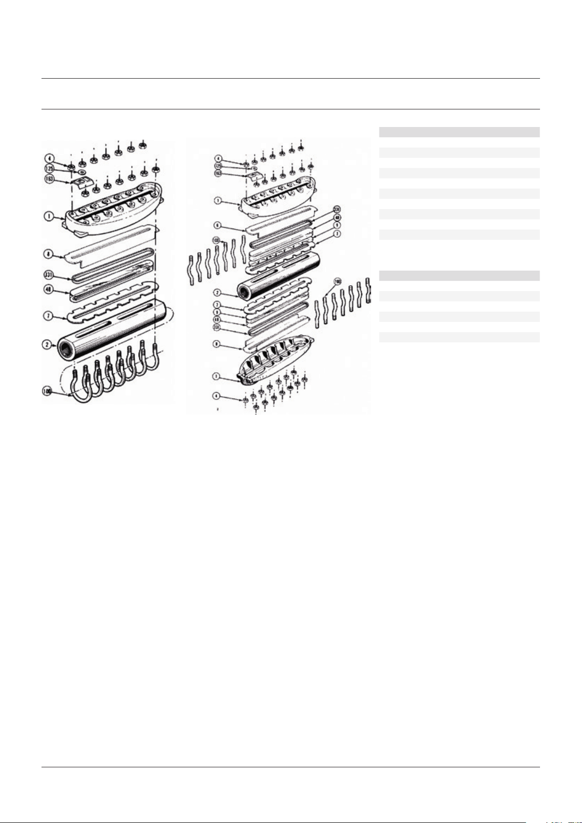
11 EXPLODED PARTS DIAGRAMS
FIGURE 6
RLC reflex
FIGURE 7
TLC transparent
PARTS LIST
Item Description
1 Cover
2 Chamber
4 Nut
48 Glass
7 Gasket
8 Cushion
9 Shield
100 Screw
125 Washer
163 Nameplate
331 Band
RECOMMENDED SPARE PARTS
Item Description Min. qty.
100 Screw 2 per sect.
4 Nut 2 per sect.
48 Glass 1
7 Gasket 2
8 Cushion 2
9 Shield* 2
* Shields are optional.
NOTE
Size 9 shown - actual gage may be shorter and require fewer bolting requirements.
10
 Loading...