

Page 1

P&E Microcomputer Systems, Inc.
P.O. Box 2044, Woburn, MA 01888, USA
TEL: (617) 353-9206 FAX: (617) 353-9205 http://www.pemicro.com
USB-ML-PPCNEXUS, PowerPC Nexus Multilink Rev. A (USB 2.0)
Technical Summary
Document # PE3356, Version 1.1
1. Introduction
2. Usage Of The PowerPC Nexus Multilink Interface
3. Driver Installation On Windows XP/2000/2003/Vista
4. Computers Running Windows 95, 98, ME, or NT
5. Using A USB Hub
6. Connecting To The Target
7. Startup Reset Sequence
8. Interface Libraries
9. Firmware Updates
1.0 Introduction
P&E’s USB POWERPC NEXUS MULTILINK Interface provides access to the JTAG/Nexus port on
Freescale PowerPC MPC55xx processors. It is the hardware interface between a USB port on a Windows
2000, 2003, XP, or Vista machine and the standard 14-pin “Berg” debug connector on the target. By
using the USB PowerPC Nexus Multilink, the user can take advantage of the JTAG/Nexus debug mode to
halt normal processor execution and use a PC to control the processor. The user can then directly control
the target’s execution, read/write registers and memory values, debug code on the processor, and
program internal or external FLASH memory devices by using the appropriate software packages. The
pin-out of the connector as specified by Freescale is:
Page 2
2.0 Usage Of The USB PowerPC Nexus Multilink Interface
The USB POWERPC NEXUS MULTILINK can communicate with a PowerPC 55xx processor.
The Multilink interface will work with targets whose processor power supply is in the range of 1.8V to
5.25V. The Multilink interface derives its power from the USB port, and as such draws less than 10mA
from the target.
The USB PowerPC Nexus Multilink has a female, Type B USB connector. Use a Type A to Type B USB
extension cable to connect the interface to the PC. The USB PowerPC Nexus Multilink is a high-power
USB device. If a USB HUB is used, it must be a self powered hub (i.e., with a power supply). By default,
the USB protocol used is 2.0.
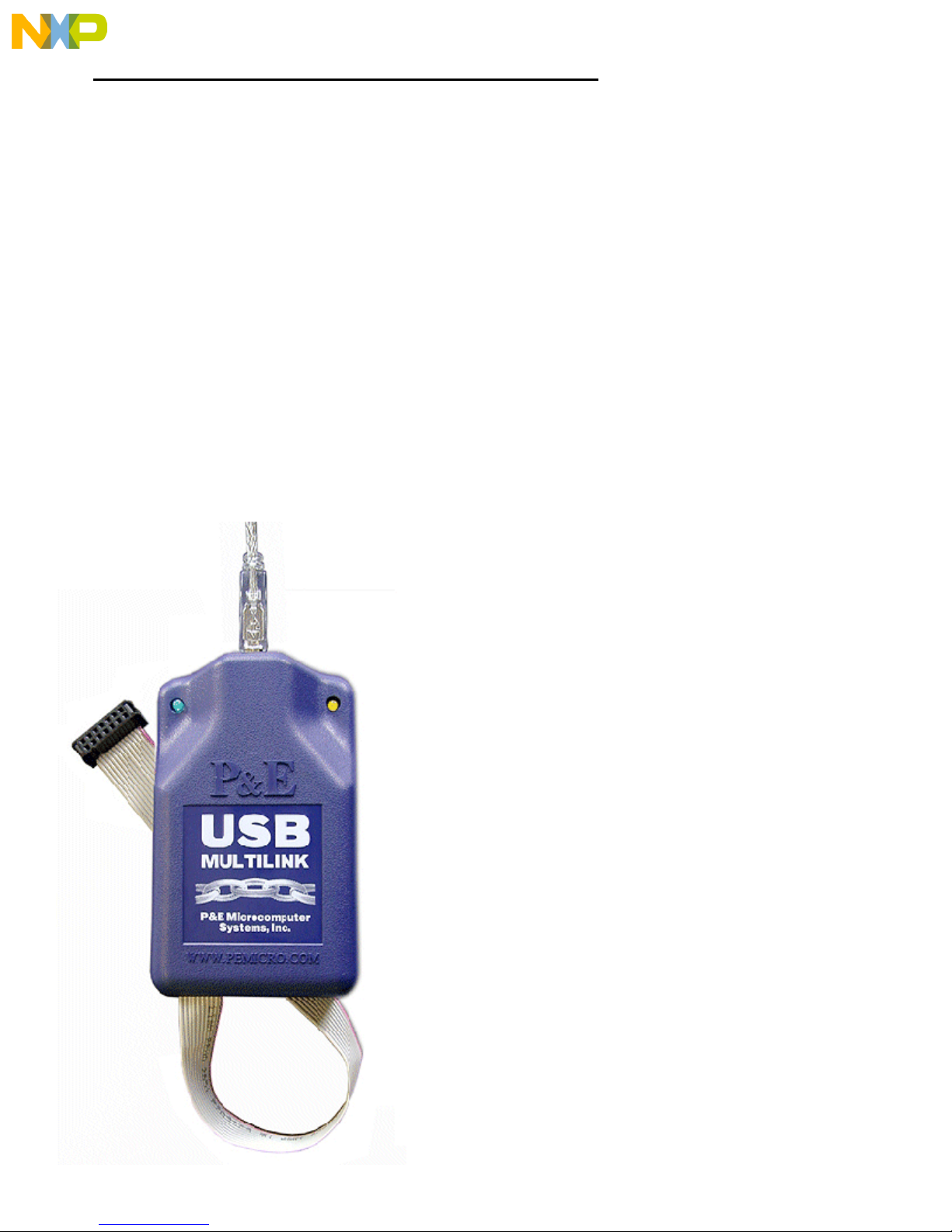
There are two LEDs located on top of the USB PowerPC Nexus Multilink interface. The Blue LED
indicates that the Multilink interface is powered and running. The Yellow LED indicates that target
power has been detected.
The 14-pin ribbon cable, which allows connection to the target debug connector, is fixed within the
Multilink housing. PIN 1 is indicated by the red stripe running down one side of the ribbon cable.
Page 3

3.0 Driver Installation On Windows XP/2000/2003/Vista
Before connecting the USB PowerPC Nexus Multilink to the PC, the appropriate drivers need to be
installed on the PC. The drivers are automatically installed when installing any of P&E’s PowerPC 55xx
development packages built after September 1, 2005. A copy of the driver installation program may also
be downloaded from the “downloads” section of P&E’s online “Support Center” located at
http://www.pemicro.com. P&E installs the following USB drivers/files on your system:
PEUSBFTDUN.EXE ---> [Windows\System]
PEUSBV1.DLL ---> [Windows\System]
PEUSBV1.SYS ---> [Windows\System]\Drivers
PEMICRO_USBCABLE_AUTO.INF ---> [Windows]\inf
Note: In general, [Windows\System] = \WINNT\SYSTEM32 for XP,2000,2003,Vista
When the USB PowerPC Nexus Multilink is detected by the PC, the operating system will automatically
scan all of the .INF files in the [Windows]\inf directory to try and find a match for the detected hardware.
The operating system should then indicate that it has found a driver for the attached “P&E USB Device.”
Follow the instructions in the “Found New Hardware Wizard” dialog to have Windows automatically
install the driver.
If you connected the Multilink interface prior to installing the drivers, Windows will not have been able to
find the appropriate driver and may have disabled the device. If you unplug and then reconnect the
device, Windows will automatically disable it even if you have installed the drivers. To force Windows to
try to load the driver again, perform the following steps while the USB PowerPC Nexus Multilink
interface is plugged into the computer:
1.) Open the Control Panel (Start Button->Settings->Control Panel)
2.) Double-click the “System” icon
3.) Select the “Hardware” tab
4.) Click the “Device Manager” button
5.) The “P&E PowerPC Nexus Multilink” device will be shown with an exclamation mark next to
it. Double-click this device.
6.) Click the “Reinstall Driver…” button and follow the dialog instructions to have Windows
automatically install the driver.
If you have purchased one of P&E’s software development packages prior to September 1, 2005, please
contact P&E to obtain the latest version which supports the USB PowerPC Nexus Multilink interface
(software support for the cable is separate from Windows USB driver support). If you are using thirdparty software, make sure you have a version which supports the USB PowerPC Nexus Multilink
interface.
4.0 Computers Running Windows 95, 98, ME, Or NT
The USB PowerPC Nexus Multilink is not supported under Windows 95 and Windows NT. The USB
PowerPC Nexus Multilink is not tested under Windows 98 and Windows ME, although drivers for these
operating systems are included in the install. For these operating systems, P&E produces the Parallel
Page 4

Port CABLEPPCNEXUS which connects the parallel port of the PC to the 14-pin debug connector on the
target. For more information, visit http://www.pemicro.com.
5.0 Using A USB Hub
The USB PowerPC Nexus Multilink is classified as a high-power USB device which is powered from the
USB bus. A high-power device requires that if a USB hub is used, it must be a self-powered hub. This
means that it has a separate power supply from which it derives its operating power (as opposed to
deriving its power from the PC). It must be able to supply 500mA per port (a high power USB device may
derive up to 500mA from the port).
6.0 Connecting To The Target
The following is the proper connection sequence to connect the PC to the target system via the USB
PowerPC Nexus Multilink interface:
1) Make sure the target power is OFF and the USB PowerPC Nexus Multilink is not connected to
either the target or the PC.
2) Connect the Multilink to the target via its ribbon cable. Make sure that the ribbon cable is plugged
into the target with the proper orientation. PIN 1 is indicated by the red stripe running down one
side of the ribbon cable.
3) Connect the Multilink to the PC via a USB extension cable. This should light the Blue LED on the
Multilink.
4) Turn the target power on. This should light the Yellow LED on the Multilink.
Before disconnecting the setup, turn the target power off.
7.0 Startup Reset Sequence
In order to use the JTAG/Nexus mode of the microcontroller, it must be initialized coming out of reset.
This is accomplished by P&E's ICD (In-Circuit Debugger) software on the host PC by generating the
following reset sequence:
1. Reset is driven low (to processor).
2. Shifting activity appears on TCLK, TDI and TDO. (PC software instructs the processor to
enable debug mode).
3. Reset is released by Multilink and will go high.
4. Shifting activity appears on TCLK, TDI and TDO. (Debug activity).
Note that if the device does not enter debug mode, the ICD debugger issues the error message “Cannot
enter background mode.” If you receive this message, you should first refer to the troubleshooting section
of this document. You should then check your hardware with a scope, logic analyzer or logic probe. First
check for power on, then check to make sure the processor oscillator is running. Finally, look for the
startup sequence given above.
8.0 Interface Libraries
Page 5

P&E produces a set of interface libraries which allow the user to directly control the USB PowerPC
Nexus Multilink from any Windows Development environment which can interact with a DLL. The
interface libraries come with examples for controlling the Multilink interface from Microsoft Visual C as
well as Borland Delphi. Details of the libraries for the PowerPC 55xx (UNITPPCNEXUS) may be found
at http://www.pemicro.com/products/product_processor.cfm?family=12.
9.0 Firmware Updates
The latest version of the firmware for the Multilink interface is included in P&E’s software development
kits. When the debugger or programmer is run, if it detects that the Multilink interface firmware needs to
be updated, it will ask the user’s permission to do this. If permission is granted, the update happens
automatically.
Alternately, the latest version of the firmware may be downloaded from the “Firmware Updates” section
of P&E’s online “Support Center” located at http://www.pemicro.com. This firmware includes a utility
which may be used to run the firmware update.
10.0 Software Packages
P&E provides several software packages which work with our PowerPC Nexus interfaces:
ICDPPCNEXUS – Source-level PowerPC Nexus debugger. This simple and easy to use debugger
supports source-level debugging on PowerPC devices including: source-level debug, software load,
hardware breakpoints, watch and memory windows, CPU display, special purpose register read/write,
and more…
PROGPPCNEXUS - Flash programmer (both interactive and automated for production). This flash
programmer is supported by a large library of flash configurations. New flash configurations are
constantly being created and the latest can be downloaded from: http://www.pemicro.com. The flash
programmer automates the task of programming flash and does not require a boot-loader to be resident
in the target.
UNITPPCNEXUS – DLL-based drivers that allow PC-based application control of the PowerPC
processor through the debug interface. Routines are provided to read and write memory, start and stop
the processor, load code, single step, and more. Also, examples are provided for some development
environments including the Microsoft Visual Studio. The libraries can be used from any development/test
platform which can link to a DLL.
The UNITPPCNEXUS library is used by other third-party vendors to enable their software packages to
work via P&E’s PowerPC Nexus interfaces.
 Loading...