

Page 1
Page 2

Purchase Agreement
P&E Microcomputer Systems, Inc. reserves the right to make changes without further notice to any
products herein to improve reliability, function, or design. P&E Microcomputer Systems, Inc. does not
assume any liability arising out of the application or use of any product or circuit described herein.
This software and accompanying documentation are protected by United States Copyright law and
also by International Treaty provisions. Any use of this software in violation of copyright law or the
terms of this agreement will be prosecuted.
All the software described in this document is copyrighted by P&E Microcomputer Systems, Inc.
Copyright notices have been included in the software.
P&E Microcomputer Systems authorizes you to make archival copies of the software and
documentation for the sole purpose of back-up and protecting your investment from loss. Under no
circumstances may you copy this software or documentation for the purpose of distribution to others.
Under no conditions may you remove the copyright notices from this software or documentation.
This software may be used by one person on as many computers as that person uses, provided that
the software is never used on two computers at the same time. P&E expects that group programming
projects making use of this software will purchase a copy of the software and documentation for each
user in the group. Contact P&E for volume discounts and site licensing agreements.
P&E Microcomputer Systems does not assume any liability for the use of this software beyond the
original purchase price of the software. In no event will P&E Microcomputer Systems be liable for
additional damages, including any lost profits, lost savings or other incidental or consequential
damages arising out of the use or inability to use these programs, even if P&E Microcomputer Systems
has been advised of the possibility of such damage.
By using this software, you accept the terms of this agreement.
© 2011 P&E Microcomputer Systems, Inc. “MS-DOS” and “Windows” are registered trademarks of
Microsoft Corporation. “Freescale” and “ColdFire” are registered trademarks of Freescale, Inc. The
Power Architecture and Power.org wordmarks and the Power and Power.org logos and related marks
are trademarks and service marks licensed by Power.org. Qorivva is a registered trademark of
Freescale Semiconductor.
P&E Microcomputer Systems, Inc.
98 Galen St.
Watertown, MA 02472
617-923-0053
http://www.pemicro.com
Manual version 1.01, April 2011
Page 3

1 INTRODUCTION ............................................................................................ 1
1.1 Overview ........................................................................................................ 1
1.2 Package Contents .......................................................................................... 1
1.3 Supported Devices ......................................................................................... 1
1.4 Recommended Materials ............................................................................... 1
1.5 Handling Precautions ..................................................................................... 2
2 HARDWARE FEATURES............................................................................... 2
2.1 TRK-MPC5634M Board Features .................................................................. 2
2.2 On-Board Virtual USB Port............................................................................. 4
2.3 TRK-MPC5634M Jumper/Connector Quick Reference.................................. 5
3 GETTING STARTED WITH THE TRK-MPC5634M ....................................... 9
4 SYSTEM SETUP .......................................................................................... 10
4.1 Overview ...................................................................................................... 10
4.2 Operating System Requirements ................................................................ 10
4.3 Software Setup............................................................................................. 10
4.4 Quick Startup................................................................................................ 11
4.5 Hardware Setup ........................................................................................... 11
5 OPERATING MODES................................................................................... 12
5.1 Overview ...................................................................................................... 12
5.2 Debug Mode................................................................................................. 12
5.3 Run Mode..................................................................................................... 12
5.4 External JTAG/Nexus Mode......................................................................... 12
6 JUMPER SETTINGS .................................................................................... 13
6.1 System Power .............................................................................................. 13
6.2 I/O Pins......................................................................................................... 13
6.3 Debug Mode................................................................................................. 14
6.4 CAN Port ...................................................................................................... 15
6.5 Virtual Serial Port ......................................................................................... 15
6.6 LIN Channels/Connectors ............................................................................ 16
6.7 MCU ............................................................................................................. 18
6.8 Boot Configuration........................................................................................ 19
TRK-MPC5634M User Manual ii
Page 4

6.9 Clock Selection .............................................................................................20
6.10 Push Buttons ................................................................................................21
6.11 LED Display Port ..........................................................................................22
6.12 DIL Switch.....................................................................................................22
6.13 Analog Input Enable .....................................................................................23
6.14 Photo Sensor Enable ....................................................................................24
6.15 Reset Sources ..............................................................................................24
6.16 OSJTAG Bootloader Enable .........................................................................25
6.17 eTPUA LED Enable ......................................................................................25
7 TRK-MPC5634M CODE DEVELOPMENT SOFTWARE.............................. 26
7.1 Using CodeWarrior With The TRK-MPC5634M............................................26
7.2 Using P&E Software With The TRK-MPC5634M..........................................26
8 TRANSITIONING TO YOUR OWN TARGET............................................... 26
8.1 Hardware Solutions At A Glance ..................................................................27
8.2 Working With P&E’s Multilink Universal or USB Qorivva Multilink................28
8.3 Working With P&E’s Cyclone MAX ...............................................................29
9 TROUBLESHOOTING.................................................................................. 30
9.1 TRK-MPC5634M Is Undetected ...................................................................30
10 TRK-MPC5634M ERRATA (REV. A ONLY)................................................. 31
iii TRK-MPC5634M User Manual
Page 5

1 INTRODUCTION
1.1 Overview
The TRK-MPC5634M is a low-cost development system supporting
Freescale MPC5634M microcontrollers in 144LQFP packages. The
Embedded OSJTAG circuitry on the TRK-MPC5634M board allows the
processor on the board to be debugged and programmed via USB from a PC.
In addition, the demo board can be powered using the USB bus.
1.2 Package Contents
The TRK-MPC5634M package includes the following items:
• TRK-MPC5634M Board
• CodeWarrior Development Studio DVD-ROM
• TRK-MPC5634M Resources CD
• USB A-to-B Cable
• Freescale Warranty Card
1.3 Supported Devices
The TRK-MPC5634M supports the following devices:
• MPC5634M microcontrollers in 144LQFP packages
1.4 Recommended Materials
• Freescale MPC5634M reference manual and datasheet
• TRK-MPC5634M board schematic
TRK-MPC5634M EVB User Manual 1
Page 6

1.5 Handling Precautions
Please take care to handle the package contents in a manner such as to
prevent electrostatic discharge.
2 HARDWARE FEATURES
The TRK-MPC5634M is a demonstration and development system for
Freescale’s MPC5634M microcontrollers in 144LQFP packages. Application
development is quick and easy using Embedded OSJTAG. An optional 14-pin
JTAG port is provided to allow the use of an external Qorivva MPC55xx/56xx
interface such as P&E’s USB Multilink or Cyclone MAX automated
programmer. P&E’s USB Multilink provides faster communication speeds and
can be used to debug both the TRK-MPC5634M and the user’s own targets.
Note: The DEMO board’s Embedded OSJTAG is intended to function with the on-
board processor only. It cannot be used to communicate with other devices.
2.1 TRK-MPC5634M Board Features
• Soldered MPC5634M LQFP144 device
• Access to MCU pins with standard headers
• Embedded OSJTAG: USB to JTAG circuitry which allows host PC to
communicate with the microcontroller through USB 2.0.
• On-board Virtual Serial Port
• ON/OFF Power Switch w/ LED indicator
• A 9VDC to 12VDC power supply input barrel connector
• Power Input Selection Jumpers for selecting the input voltage source:
• Power Input from USB Connector
• Power Input from DC Power Jack
• Freescale MC3390x
• Jumper to select BAM source:
• From internal memory
• From CAN
• From LIN Flex
2 TRK-MPC5634M EVB User Manual
Page 7

• RESET Push Button and LED indicator w/ enable
• User Features:
• 4 User Push Buttons w/ enable and pull-up & pull-down options
• 4 DIL switches w/ enable and pull-up & pull-down options
• 10K Ohm POT connected to an ADC input channel w/ enable
• 1 photocell w/ enable
• 4 User LED’s w/ enable
• 1 RS232 interface w/ enable (DB9 and transceiver footprint only)
• 1 CAN interface w/ enable to high-speed CAN transceiver with
DB9 CAN connector
• 2 LIN channels w/ enable sharing one LIN transceiver with two
standard LIN connectors
• 4 distinct GND test points
• Specifications:
• Board Size 4.7” x 4.3”
• Power Input:
• USB Cable: 5VDC, 500mA max
• DC Power Jack: 2.1/5.5mm barrel connector, 9VDC to
12VDC Center Positive
TRK-MPC5634M EVB User Manual 3
Page 8
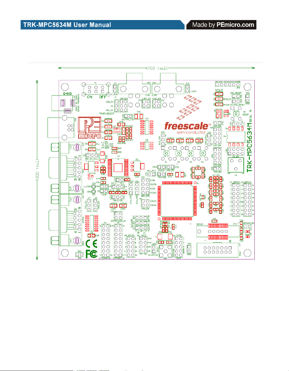
Figure 2-1: Top Component Placement
2.2 On-Board Virtual USB Port
The TRK-MPC5634M board has a built-in virtual serial port which may be
connected to the MPC5634M processor’s SCI RXD/TXD. This allows certain
PC applications to be able to connect in a serial fashion to the microcontroller
without the actual use of serial port hardware.
4 TRK-MPC5634M EVB User Manual
Page 9

2.3 TRK-MPC5634M Jumper/Connector Quick Reference
Default Jumper Settings
The following is a list of default jumper settings for TRK-MPC5634M board.
The settings listed indicate the “on” (or installed) position.
Default Jumper Settings
JUMPER OPTION SETTINGS DESCRIPTION
System Power
J1
Source Select
SBC I/O LED
J2
Pull Up/Down
J3 SBC I/O Signal
SBC DBG
J4
Short to GND
(default: OFF)
SBC DBG Pull
J5
J6
Up
(default: OFF)
CAN Signals to
Transceiver
Enable
1-2 (default)
2-3
1-2 (default) Pull Up
2-3 Pull Down
1-2 (default) I/O-0
2-3 I/O-1
1-2 Short SBC DBG Pin to GND,
1-2
1-2, 3-4
(default)
USB OSJTAG Supplies
5VDC
SBC MC33905 Supplies
5VDC
Bypass R21 and D13
Pull Up SBC DBG Pin to
SBC Power Supply via 330
Ohm Resistor
Enables TXD and RXD
signals to CAN Transceiver
TRK-MPC5634M EVB User Manual 5
Page 10

Default Jumper Settings
J7
J8
J9
(default: OFF)
J10
(default: OFF)
LIN0 Signals to
J11
LIN1 Signals to
J12
(default: OFF)
RS232 TXD
Signal
RS232 RXD
Signal
LIN1 VBus
Enable
LIN0 VBus
Enable
Connector
Enable
Connector
Enable
1-2 (default)
2-3
1-2 (default)
2-3
1-2
1-2
1-2 (default),
3-4 (default)
1-2, 3-4 Connects LIN1 Signals to
MCU TXD to Virtual Serial
Port
MCU TXD to RS232
Transceiver
MCU RXD to Virtual Serial
Port
MCU RXD to RS232
Transceiver
Provides Power to LIN1
Connector
Provides Power to LIN0
Connector
Connects LIN0 Signals to
LIN0 Connector
LIN1 Connector
1-2 (default) MCU LIN0TX to Transceiver
CT7 LIN TXD Signal
2-3 MCU LIN1TX to Transceiver
1-2 (default) MCU LIN0RX to Transceiver
CT8 LIN RXD Signal
2-3 MCU LIN1RX to Transceiver
6 TRK-MPC5634M EVB User Manual
Page 11

Default Jumper Settings
CT1 Cut Trace
J16 SBC SPI
External Crystal
Circuitry Enable
CT4
CT5
Cut Trace
(default: ALL
ON)
External Crystal
Circuitry Enable
Cut Trace
(default: ALL
ON)
shorrted
(default)
Cut traces
on PCB
board:
1-2 (default)
3-4(default)
5-6(default)
7-8(default)
shorted
(default)
shorted
(default)
Provides Power to MCU;
Current Measurement
Connects MCU SPI signals
to SBC SPI
XTAL
EXTAL
External
J23
J24
TRK-MPC5634M EVB User Manual 7
Oscillator via
SMA Enable
(default: OFF)
Push Button
Active High or
Low; Opposite
of J25
1-2 EXTAL
1-2 (default) Active Low
2-3 Active High
Page 12

Default Jumper Settings
J25
J26
J27
J28
J29
Pull Up/Down
Opposite of J24
Signals Enable
(default: ALL
(default: ALL
Signals Enable
(default: ALL
Active High or
Push Button
Enable;
Push Button
ON)
LED Signals
Enable
ON)
DIL Switch
ON)
DIL Switch
Low
1-2 (default) Pull Up
2-3 Pull Down
1-2 (default),
3-4 (default),
5-6 (default),
7-8 (default)
1-2 (default),
3-4 (default),
5-6 (default),
7-8 (default)
1-2 (default),
3-4 (default),
5-6 (default),
7-8 (default)
1-2 (default) Active High
2-3 Active Low
Connects MCU Port
EMIOS0, EMIOS2, EMIOS4,
and EMIOS8 to Push
Buttons Correspondingly
Connects MCU Port
EMIOS9, EMIOS10,
EMIOS11, and EMIOS12 to
LEDs Correspondingly
Connects MCU Port
eTPUA20, eTPUA21,
eTPUA22, and eTPUA23 to
DIL Switch Correspondingly
J30
J31
J32
J33
8 TRK-MPC5634M EVB User Manual
Analog Input
Enable
Photo Sensor
Enable
SBC Reset to
MCU Enable
(default: OFF)
OSJTAG Reset
to MCU Enable
1-2 (default)
1-2 (default)
1-2
1-2 (default)
Connects MCU AN17 to
Potentiometer
Connects MCU AN35 to
Photo Cell
Enables SBC Reset Signal
to Trigger MCU Reset
Enables OSJTAG Reset
Signal to Trigger MCU Reset
Page 13

Default Jumper Settings
CT9
J35
J37 BOOTCFG1
J38 PLLREF
CT2 WKPCFG
System Reset
Enable
OSJTAG
Bootloader
Enable
(default: OFF)
1-2 (default)
1-2
1-2
2-3 (default)
1-2 (default)
2-3
1-2 (default)
2-3
Connects Reset Sources to
MCU Reset Signal
Forces OSJTAG to start up
in bootloader mode for
firmware updates
Processor uses serial boot
mode
Processor uses internal boot
mode
Processor uses a crystal
clock source
Processor uses an external
clock source
Processor pins are
configured as weak pull
down
Processor pins are
configured as weak pull up
2.4 External Power Supply Requirement
DC Power Jack: Center Positive 2.1mm/5.5mm Barrel Connector
Input Voltage Range: 9VDC to 12VDC
Note: In order for LIN and CAN to operate properly, SBC must be powered
externally.
TRK-MPC5634M EVB User Manual 9
Page 14

3 GETTING STARTED WITH THE TRK-MPC5634M
The TRK-MPC5634M is a low-cost board targeting quick microcontroller
evaluation. Please refer to the TRK-MPC5634M Quick Start Guide for
instructions on how to install software, connect the TRK-MPC5634M to your
PC, and run quick demonstrations.
4 SYSTEM SETUP
4.1 Overview
The Embedded OSJTAG driver is required to operate the TRK-MPC5634M
using a PC. The Embedded OSJTAG driver should be installed with the
CodeWarrior Development Studio software before the PC is connected to the
TRK-MPC5634M.
Because new features and bug fixes are implemented frequently, it is strongly
recommended that the user download and install the latest OSJTAG drivers
from http://www.pemicro.com/osbdm.
4.2 Operating System Requirements
The following are the resources required to run the CodeWarrior Development
Studio and the TRK-MPC5634M:
• A PC-compatible system running Windows 2000, Windows XP,
Windows Vista, or Windows 7
• 128MB of available system RAM, and 1GB of available hard disk
space
• A DVD-ROM drive for software installation
• A USB port
4.3 Software Setup
4.3.1 Installing CodeWarrior Development Studio
To install the CodeWarrior Development Studio, follow the instructions on the
DVD-ROM.
10 TRK-MPC5634M EVB User Manual
Page 15

4.3.2 Installing P&E Resources
Use the TRK-MPC5634M Resources in the DVD-ROM to access and install
P&E resources for the DEMO board. These materials are not required for
operation. The TRK-MPC5634M Resources CD-ROM contains the following
support materials:
• TRK-MPC5634M User Manual (this document)
• TRK-MPC5634M Board Schematic
• TRK-MPC5634M Component Breakdown List
• P&E Evaluation Software
• Links to Freescale documentation, P&E Discussion Forums, and
TRK-MPC5634M FAQs.
4.4 Quick Startup
Only a few steps are required to get the TRK-MPC5634M up and running.
Please reference the Quick Start Guide.
4.5 Hardware Setup
4.5.1 First-Time Connection
The TRK-MPC5634M may be connected to a PC through a USB port.
Connection steps are listed below in typical order:
1. Install the required software, as described in the previous section.
2. Make sure the jumper USB_5V for POWER_SELECT is installed.
3. Plug the USB cable A-M connector into a free USB port of the PC.
4. Plug the USB cable B-M connector into the USB connector on the
TRK-MPC5634M Board.
5. The operating system will recognize the Embedded OSJTAG circuitry
and P&E’s USB to Serial circuitry. Depending on the operating system, you may see the “Found New Hardware Wizard” dialog to assist
you with installation. Follow the onscreen Windows instructions to
install the OSJTAG driver (these instructions may vary slightly
depending on your specific operating system).
6. Select the “Install the software automatically (Recommended)” option
TRK-MPC5634M EVB User Manual 11
Page 16

and click the “Next” button. Windows will install the driver files to your
system. At the end of the installation, click the “Finish” button.
Note: Depending on the operating system, you may see the “Found New Hardware
Wizard” dialog again to assist you with software installation for “PEMicro USB
Serial Port (i1).” Follow the onscreen Windows instructions.
1. Select the “Install the software automatically (Recommended)” option
and click the “Next” button.
2. Windows will install the driver files to your system. Click the “Finish”
button to exit the “Found New Hardware Wizard.”
If the TRK-MPC5634M hardware interface driver is now properly installed on
your system, the green USB LED on the TRK-MPC5634M Base Board should
be illuminated. In addition, if you turn on the system power of the TRKMPC5634M you will see the yellow Power LED illuminate.
5 OPERATING MODES
5.1 Overview
The TRK-MPC5634M’s Embedded OSJTAG circuitry, featured hardware
components, and optional external JTAG header make it a versatile
development tool. Below are some of the featured operating modes of the
TRK-MPC5634M.
5.2 Debug Mode
A host communicates with the TRK-MPC5634M through the Embedded
OSJTAG circuitry. Either the CodeWarrior Development Studio or P&E’s
Qorivva software tools will work with the TRK-MPC5634M. Please refer to
Section 7 - TRK-MPC5634M CODE DEVELOPMENT SOFTWARE for more
information.
5.3 Run Mode
The TRK-MPC5634M’s rich component list empowers it to perform a variety
of tasks. Once an application is developed, debugged, and programmed
properly into the microcontroller’s internal flash memory, it can run with or
without connecting to a host.
12 TRK-MPC5634M EVB User Manual
Page 17
5.4 External JTAG/Nexus Mode
The TRK-MPC5634M has an optional JTAG/Nexus header for debugging and
programming the on-board MPC5634M microcontroller using an external
Qorivva hardware tool, such as P&E’s USB Multilink or Cyclone MAX. Please
refer to Section 8 - TRANSITIONING TO YOUR OWN TARGET for more
information. A user can take advantage of this mode to develop a targetspecific MPC5634M system and compare it with the TRK-MPC5634M when
necessary.
6 JUMPER SETTINGS
This section describes the various jumpers settings that are available on the
TRK-MPC5634M. Figures depict the default setting for each jumper.
Some board options are implemented as cut-trace options. To change from
the default settings, the traces need to be cut and jumpers added to set the
desired feature.
6.1 System Power
The TRK-MPC5634M board provides 3 power options: SBC MC33905 or
LDO can regulate external power to 5VDC, or USB can provide 5VDC
through OSJTAG.
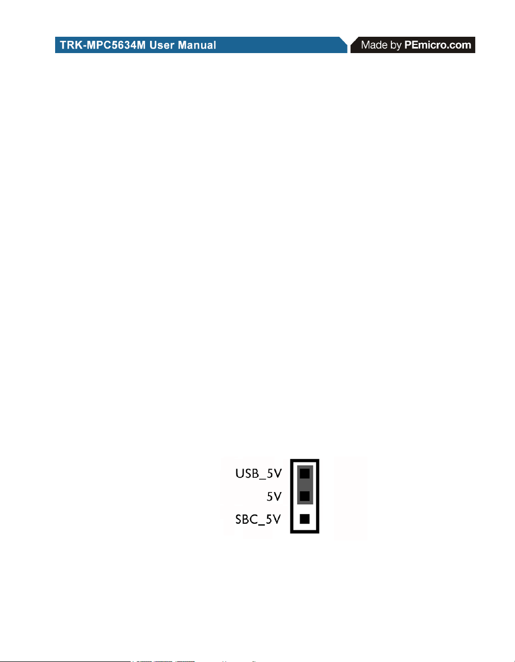
6.1.1 J1 - System Power
1-2 USB OSJTAG Supplies 5VDC (default)
3-4 SBC MC33905 Supplies 5VDC
Figure 6-2: System Power (J1)
TRK-MPC5634M EVB User Manual 13
Page 18
6.2 I/O Pins
The SBC MC33905 provides three I/O pins. Two of them are jumper (J3)
selectable to two LEDs, which are further jumper (J2) selectable to pull-up or
pull-down.
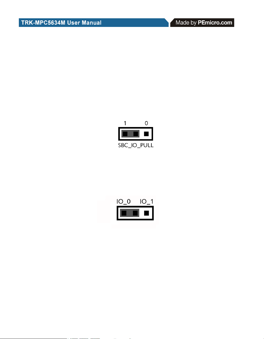
6.2.1 J2 - SBC I/O LED Pull Up/Down
1-2 Pull Up (default)
3-4 Pull Down
Figure 6-3: SBC I/O LED Pull Up/Down (J2)
6.2.2 J3 - SBC I/O Signal
1-2 I/O-0 (default)
2-3 I/O-1
Figure 6-4: SBC I/O Signal (J3)
6.3 Debug Mode
The SBC MC33905 has a DBG pin to put it into debug mode. Jumpers J4 and
J5 are designed for this purpose.
6.3.1 J4 - SBC DBG Short To GND
1-2 Short SBC DBG Pin to GND, Bypass R21 and D13 (default: OFF)
14 TRK-MPC5634M EVB User Manual
Page 19

Figure 6-5: SBC DBG Short To GND (J4)
6.3.2 J5 - SBC DBG Pull Up
1-2 Pull Up SBC DBG Pin to SBC Power Supply via 330 Ohm Resistor
(default: OFF)
Figure 6-6: SBC DBG Pull Up (J5)
6.4 CAN Port
The TRK-MPC5634M board has implemented a CAN port.
Note: In order for LIN and CAN to operate properly, SBC must be powered
externally.
6.4.1 J6 – CAN Signals To Transceiver Enable CAN_EN
Enables TXD and RXD signals to the CAN transceiver. By default, the
jumpers are installed.
Figure 6-7: CAN_EN (J6)
6.5 Virtual Serial Port
The TRK-MPC5634M board has a built-in virtual serial port which may be
connected to the MPC5504P processor’s SCI. This allows certain PC
TRK-MPC5634M EVB User Manual 15
Page 20

applications to be able to connect in a serial fashion to the microcontroller
without the actual use of serial port hardware. It can be enabled or disabled
by installing or removing the jumpers J7 and J8.
6.5.1 J7 - RS232 TXD Signal
Figure 6-8: TXD_EN (J7)
6.5.2 J8 - RS232 RXD Signal
Figure 6-9: RXD_EN (J8)
6.6 LIN Channels/Connectors
The TRK-MPC5634M board provides two jumper selectable LIN channels to
two jumper selectable LIN connectors.
Note: In order for LIN and CAN to operate properly, SBC must be powered
externally.
6.6.1 J9 - LIN1 VBus Enable
1-2 Provides Power to LIN1 Connector (default: OFF)
Figure 6-10: LIN1 VBus Enable (J9)
16 TRK-MPC5634M EVB User Manual
Page 21
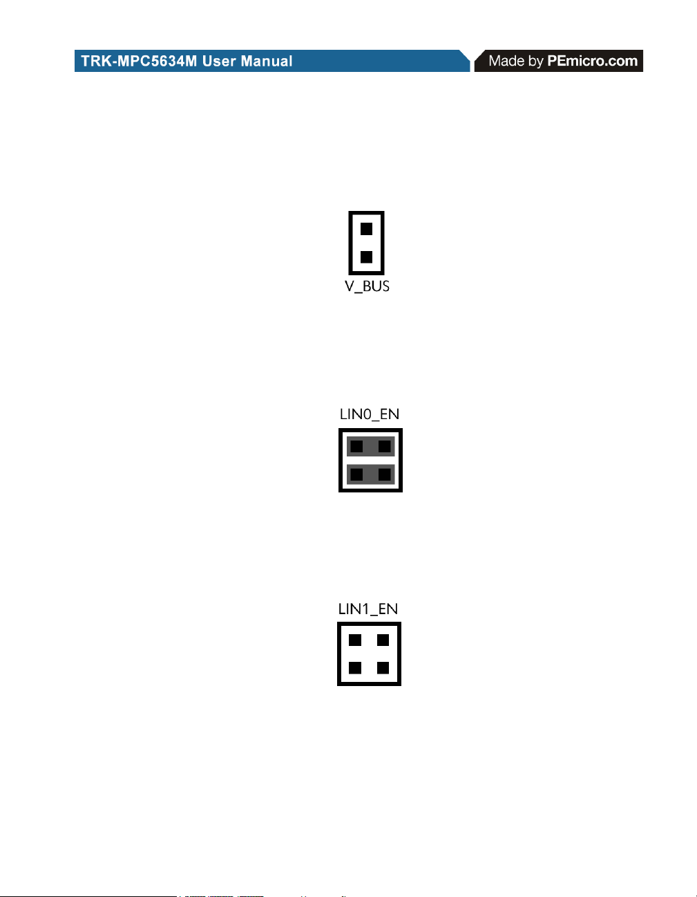
6.6.2 J10 - LIN0 VBus Enable
1-2 Provides Power to LIN0 Connector (default: OFF)
Figure 6-11: LIN0 VBus Enable (J10)
6.6.3 J11 - LIN0 Signals To Connector Enable
1-2, 3-4 Connects LIN0 Signals to LIN0 Connector (default)
Figure 6-12: LIN0 Signals To Connector Enable (J11)
6.6.4 J12 - LIN1 Signals To Connector Enable
1-2, 3-4 Connects LIN1 Signals to LIN1 Connector (default: OFF)
Figure 6-13: LIN1 Signals To Connector Enable (CT7)
6.6.5 CT7 - LIN TXD Signal
1-2 MCU LIN0TX to Transceiver (default)
2-3 MCU LIN1TX to Transceiver
TRK-MPC5634M EVB User Manual 17
Page 22

Figure 6-14: LIN TXD Signal (CT7)
6.6.6 CT8 - LIN RXD Signal
1-2 MCU LIN0RX to Transceiver (default)
2-3 MCU LIN1RX to Transceiver
Figure 6-15: LIN RXD Signal (CT8)
6.7 MCU
6.7.1 CT1 - Cut Trace
1-2 shorted (default)
Figure 6-16: MCU VDD Enable (CT1)
6.7.2 J16 - SBC_SPI
Cut traces on PCB: 1-2 (default), 3-4 (default), 5-6 (default), 7-8 (default) -
18 TRK-MPC5634M EVB User Manual
Page 23

connects MCU_SPI signals to SBC_SPI
6.8 Boot Configuration
6.8.1 J37 - BOOTCFG1
1-2 Processor uses serial boot mode
2-3 Processor uses internal boot mode (default)
Figure 6-17: SBC_SPI (J16)
Figure 6-18: BOOTCFG1 (J37)
6.8.2 J38 - PLLREF
1-2 Processor uses a crystal clock source (default)
2-3 Processor uses an external clock source
Figure 6-19: PLLREF (J38)
TRK-MPC5634M EVB User Manual 19
Page 24

6.8.3 CT2 - WKPCFG
1-2 Processor pins are configured as weak pull down (default)
2-3 Processor pins are configured as weak pull up
Figure 6-20: MPC5634M WKPCFG (CT2)
6.9 Clock Selection
6.9.1 CT4- External Crystal Circuitry Enable Cut Traces
1-2 XTAL
(default: shorted)
Figure 6-21: External Crystal Circuitry Enable (CT4)
6.9.2 CT5- External Crystal Circuitry Enable
1-2 EXTAL
(default: shorted)
Figure 6-22: External Crystal Circuitry Enable (CT5)
20 TRK-MPC5634M EVB User Manual
Page 25

6.9.3 J23 - External Oscillator via SMA Enable
1-2 EXTAL (default: OFF)
Figure 6-23: External Oscillator via SMA Enable (J23)
6.10 Push Buttons
The TRK-MPC5634M board is designed with 4 jumper enabled push buttons
with jumper selectable active high or low states.
6.10.1 J24 - Push Button Active High or Low (Opposite of J25)
1-2 Active Low (default)
2-3 Active High
Figure 6-24: Push Button Active High or Low (J24)
6.10.2 J25 - Push Button Pull Up/Down Enable (Opposite of J24)
1-2 Pull Up (default)
2-3 Pull Down
Figure 6-25: Push Button Pull Up/Down Enable (J25)
TRK-MPC5634M EVB User Manual 21
Page 26
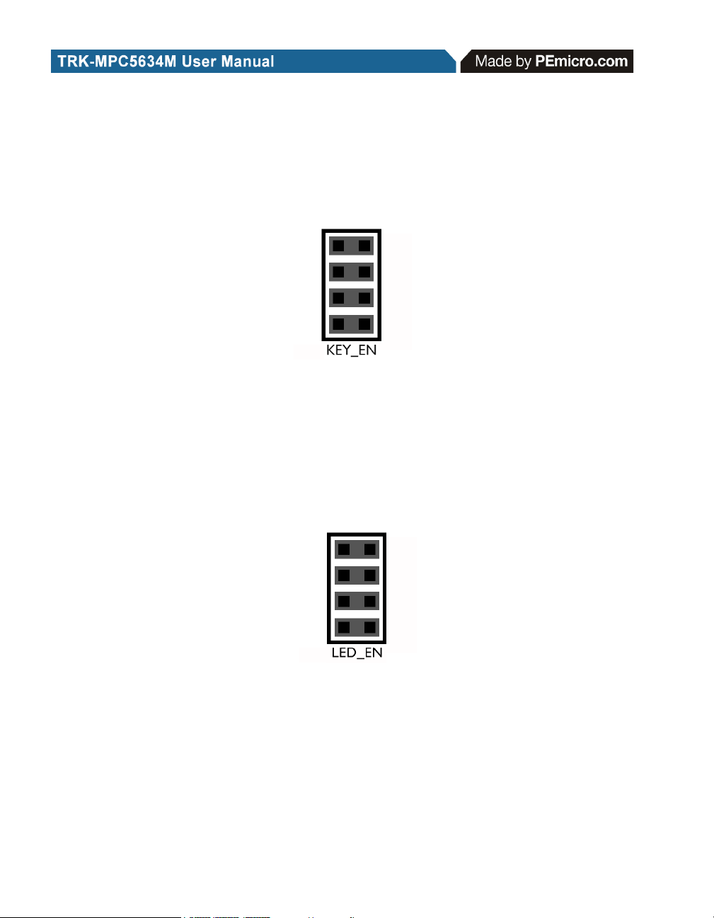
6.10.3 J26 - Push Button Signals Enable
1-2, 3-4, 5-6, 7-8 Connects MCU Port EMIOS0, EMIOS2, EMIOS4 and
EMIOS8 to Corresponding Push Buttons (default: ALL ON)
Figure 6-26: Push Button Signals Enable (J26)
6.11 LED Display Port
The TRK-MPC5634M has 4 LEDs connected to signals EMIOS9, EMIOS10,
EMIOS11, and EMIOS12. They can be enabled or disabled by installing or
removing the corresponding jumper, J27, in the LED_ENABLE header.
6.11.1 J27 - LED Display Enable Port LED_ENABLE
Enables all LED outputs. This is the default setting.
Figure 6-27: LED Display Enable Header LED_ENABLE (J27)
6.12 DIL Switch
The TRK-MPC5634M board is designed with a 4 jumper-enabled DIL Switch
signal with jumper-selectable active high or low states.
22 TRK-MPC5634M EVB User Manual
Page 27
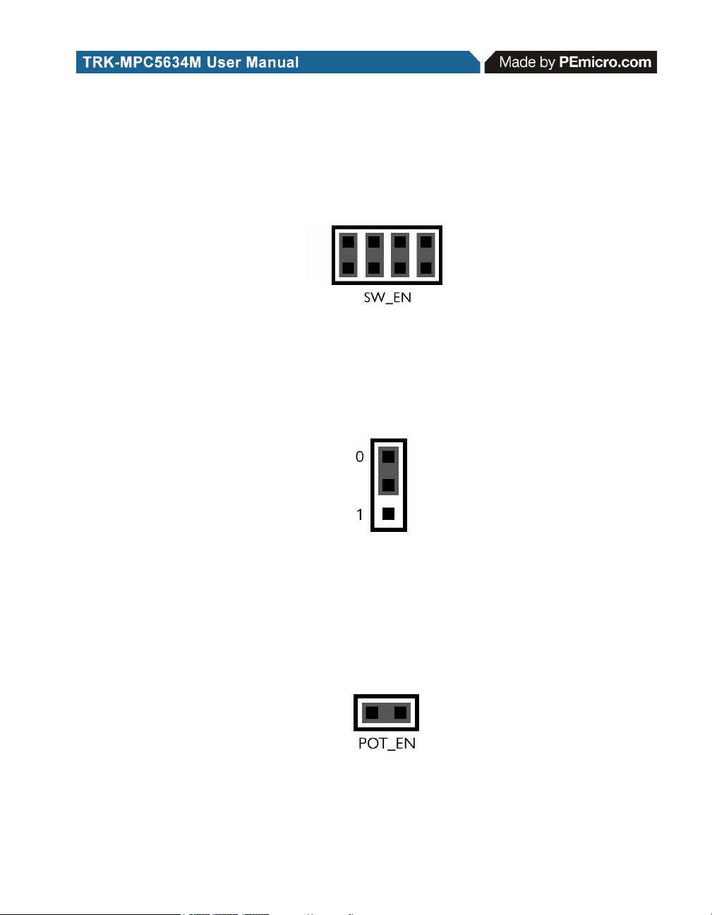
6.12.1 J28 - DIL Switch Signals
1-2, 3-4, 5-6, 7-8 Connects MCU Port eTPUA20, eTPUA21, eTPUA22, and
eTPUA23 to Corresponding DIL Switch (default: ALL ON)
Figure 6-28: DIL Switch Signals (J28)
6.12.2 J29 - DIL Switch Active High or Low
1-2 Active Low (default)
2-3 Active High
Figure 6-29: DIL Switch Active High or Low (J29)
6.13 Analog Input Enable
6.13.1 J30 - Analog Input Enable
1-2 Connects MCU AN17 to Potentiometer (default)
Figure 6-30: Analog Input Enable (J30)
TRK-MPC5634M EVB User Manual 23
Page 28

6.14 Photo Sensor Enable
6.14.1 J31 - Photo Sensor Enable
1-2 Connects MCU AN35 to Photo Sensor (default)
Figure 6-31: Photo Sensor Enable (J31)
6.15 Reset Sources
The TRK-MPC5634M board is designed with 3 reset sources: From SBC
MC33905, from OSJTAG, and from the Reset Button.
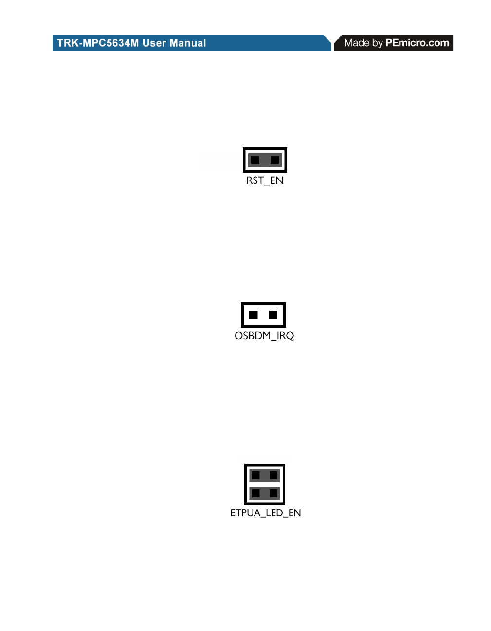
6.15.1 J32 - SBC Reset to MCU Enable
1-2 Enables SBC Reset Signal to Trigger MCU Reset (default: OFF)
Figure 6-32: SBC Reset to MCU Enable (J32)
6.15.2 J33 - OSJTAG Reset to MCU Enable
1-2 Enables OSJTAG Reset Signal MCU Reset (default)
Figure 6-33: OSJTAG Reset to MCU Enable (J33)
24 TRK-MPC5634M EVB User Manual
Page 29
6.15.3 CT9 - System Reset Enable
1-2 Connects Reset Sources to MCU Reset Signal (default)
Figure 6-34: System Reset Enable (CT9)
6.16 OSJTAG Bootloader Enable
6.16.1 J35 - OSJTAG Bootloader Enable
1-2 Forces OSJTAG to start up in bootloader mode for firmware updates
(default: OFF)
Figure 6-35: OSJTAG IRQ Enable (J35)
6.17 eTPUA LED Enable
6.17.1 J39 - eTPUA LED Enable
1-2 Connects MCU eTPUA2 to LED (default)
3-4 Connects MCU eTPUA5 to LED (default)
Figure 6-36: eTPUA LED Enable (J39)
TRK-MPC5634M EVB User Manual 25
Page 30

7 TRK-MPC5634M CODE DEVELOPMENT SOFTWARE
The TRK-MPC5634M includes P&E’s OSJTAG circuitry, so no external
Qorivva hardware tool is needed to debug and program the TRK-MPC5634M.
A user only needs to connect the TRK-MPC5634M to their PC to start
developing code for it.
The TRK-MPC5634M package comes with a special edition of Freescale’s
CodeWarrior studio. In addition, P&E’s evaluation software for Qorivva is
available in the TRK-MPC5634M Resources section of the TRK-MPC5634M
Resources CD, or online at www.pemicro.com. A user may use either
CodeWarrior or P&E software tools to develop code for the TRK-MPC5634M.
7.1 Using CodeWarrior With The TRK-MPC5634M
The CodeWarrior studio supports Freescale’s Qorivva devices. It offers C,
C++, and assembly-level support, and provides debugging capabilities based
on P&E’s debug and programming technologies.
A programming or debug session with the project-based CodeWarrior IDE
may be launched by double-clicking on the project name (the format is
projectname.mcp) from your file storage. Its tutorials, FAQs, and quick start
guides are easy to follow and will allow you use pre-built templates to begin
creating a new project in a short time. Codewarrior tutorials can be followed
based on the instructions provided.
7.2 Using P&E Software With The TRK-MPC5634M
P&E offers an integrated development environment for Freescale’s Qorivva
devices, which combines a GNU C compiler, in-circuit debugger, and flash
memory programmer. The debugger supports both assembly and C sourcelevel debugging. The programmer can program/reprogram both internal and
external flash devices in-circuit.
8 TRANSITIONING TO YOUR OWN TARGET
Once you have finished working with the TRK-MPC5634M and are ready to
build your own target, you will need a hardware tool to allow you to develop
using your own board.
The Multilink Universal and USB Qorivva Multilink are development tools that
are functionally comparable to the Embedded Multilink circuitry on the TRK-
26 TRK-MPC5634M EVB User Manual
Page 31

MPC5634M. Either interface will enable you to debug your code and program
it onto your target. The Cyclone MAX is a more versatile and robust
development tool with advanced features and production capabilities.
These solutions all work with Freescale’s CodeWarrior as well as P&E
software, and provide a seamless transition to working with your own
hardware. More information is available below to assist you in choosing the
appropriate development tool for your needs.
8.1 Hardware Solutions At A Glance
The Multilink Universal and USB Qorivva Multilink each offer an affordable
and compact solution for your development needs, and allow debugging and
programming to be accomplished simply and efficiently. Those doing rapid
development will find these interfaces easy to use and fully capable of fastpaced debugging and programming.
The Cyclone MAX is a more complete solution designed for both development
and production. The Cyclone MAX features automated power switching,
multiple communications interfaces (including USB, Ethernet, and Serial),
stand-alone programming functionality, and many other advanced
capabilities.
Below is an overview of the features and intended use of the Multilink
Universal and USB Qorivva Multilink, as well as the Cyclone MAX.
8.1.1 Multilink Universal and USB Qorivva Multilink Features
• Direct user control of target’s execution
• Programming and debugging capabilities
• Read/write registers and memory values
• Compact and lightweight
• Communication via USB 2.0
• Supported by P&E software and Freescale’s CodeWarrior
• USB Qorivva Multilink supports Freescale Qorivva MPC55xx/56xx.
• Multilink Universal supports Freescale Qorivva MPC55xx/56xx,
HCS08, HC(S)12(X), RS08, ColdFire V1/+V1, ColdFire V2-4, and
Kinetis ARM.
TRK-MPC5634M EVB User Manual 27
Page 32

8.1.2 Cyclone MAX Key Features
Advanced programming and debugging capabilities, including:
• PC-Controlled and User-Controlled Stand-Alone Operation
• Interactive Programming via Host PC
• In-Circuit Debugging, Programming, and Testing
• Compatible with Freescale’s ColdFireV2/3/4, Power Architecture 5xx/
8xx, Qorivva MPC55xx/56xx, and Kinetis ARM microcontroller
families
• Communication via USB, Serial, and Ethernet Ports
• Multiple image storage
• LCD screen menu interface
• Supported by P&E software and Freescale’s CodeWarrior
8.2 Working With P&E’s Multilink Universal or USB Qorivva Multilink
Figure 8-1: Multilink Universal (left) & USB Qorivva Multilink (right)
8.2.1 Product Features & Implementation
P&E’s Multilink Universal and USB Qorivva Multilink each connect your target
to your PC and allow the PC access to the debug mode on Freescale’s
Qorivva MPC55xx/56xx microcontrollers (the Multilink Universal also supports
several other Freescale processors). These interfaces connect between a
USB port on a Windows 2000/XP/2003/Vista/7 machine and a standard 14pin JTAG/Nexus connector on the target.
By using either of these interfaces, the user can take advantage of the
background debug mode to halt normal processor execution and use a PC to
control the processor. The user can then directly control the target’s
28 TRK-MPC5634M EVB User Manual
Page 33

execution, read/write registers and memory values, debug code on the
processor, and program internal or external FLASH memory devices. The
Multilink Universal and USB Qorivva Multilink each enable you to debug,
program, and test your code on your board.
8.2.2 Software
The Multilink Universal and USB Qorivva Multilink interfaces each work with
Codewarrior as well as P&E’s in-circuit debugger and flash programmer to
allow debug and flash programming of the target processor. P&E’s USB
Qorivva Multilink Development Packages come with the USB Qorivva
Multilink interface, as well as flash programming software, in-circuit
debugging software, Windows IDE, and a register file editor.
8.3 Working With P&E’s Cyclone MAX
Figure 8-2: P&E’s Cyclone MAX
8.3.1 Product Features & Implementation
P&E’s Cyclone MAX is an extremely flexible tool designed for debugging,
testing, and in-circuit flash programming of Freescale’s ColdFireV2/3/4,
Power Architecture 5xx/8xx, Qorivva MPC55xx/56xx, and Kinetis ARM
microcontrollers. The Cyclone MAX connects your target to the PC via USB,
Ethernet, or Serial Port and enables you to debug your code, program, and
test it on your board. After development is complete the Cyclone MAX can be
used as a production tool on your manufacturing floor.
For production, the Cyclone MAX may be operated interactively via Windowsbased programming applications as well as under batch or .dll commands
from a PC. Once loaded with data by a PC it can be disconnected and
operated manually in a stand-alone mode via the LCD menu and control
buttons. The Cyclone MAX has over 7Mbytes of non-volatile memory, which
TRK-MPC5634M EVB User Manual 29
Page 34

allows the on-board storage of multiple programming images. When
connected to a PC for programming or loading it can communicate via the
ethernet, USB, or serial interfaces.
8.3.2 Software
The Cyclone MAX comes with intuitive configuration software and interactive
programming software, as well as easy to use automated control software.
The Cyclone MAX also functions as a full-featured debug interface, and is
supported by Freescale’s CodeWarrior as well as development software from
P&E.
P&E’s Cyclone MAX is also available bundled with additional software as part
of various Development Packages. In addition to the Cyclone MAX, these
Development Packages include in-circuit debugging software, flash
programming software, a Windows IDE, and a register file editor.
9 TROUBLESHOOTING
9.1 TRK-MPC5634M Is Undetected
Q: The connection assistant indicates that my TRK-MPC5634M is undetected
even though I have connected the hardware to my USB port. What should I
do?
A: The connection assistant, which displays in either Codewarrior or P&E’s
development software, is a dialog which allows the user to connect to the
TRK-MPC5634M hardware. If this dialog indicates that the TRK-MPC5634M
hardware is not connected to the PC, the first step is to make sure that the
TRK-MPC5634M hardware is connected to the PC via a USB 2.0 high-speed
cable. If it is connected, unplug and then plug in the USB cable on the TRKMPC5634M board and click refresh in the connection assistant. If the
hardware still does not show up, try the following remedies:
(A) Re-Install the USB driver
If the Multilink device does not show up in the device manager, re-install the
CodeWarrior Development Studio software from the DVD-ROM. After driver
installation, unplug the TRK-MPC5634M from the PC and reboot the PC.
When the reboot has completed, connect the interface to the PC with the USB
2.0 cable. Run the software again to see if the interface is now detected.
(B) USB Hub Usage
30 TRK-MPC5634M EVB User Manual
Page 35

The TRK-MPC5634M is a high-power USB device. If a USB Hub is used, it
must be a self-powered hub (i.e., with its own power supply). If the Hub is not
self-powered the TRK-MPC5634M will not work. In general, USB ports
located directly on the PC are high-power (self-powered) ports.
10 TRK-MPC5634M ERRATA (REV. A ONLY)
The following errata should be noted for Rev. A of the TRK-MPC5634M.
Workarounds are listed, when available.
1. VDDREG is floating.
Workaround : Rev. A boards are shipped with an extra jumper
between pins 5+6 of JP9 to connect VDDREG to the 5V power
supply.
2. JCOMP is not connected on the 14-pin JTAG header (JP7) used for
external debug tools.
Workaround : Rev. A boards have a wire soldered to connect the
JCOMP signal. If the user wishes to install the Nexus/Mictor
connector, this wire may need to be removed. OSJTAG is not affected
by this erratum.
3. OSJTAG is operating at 5V debug logic instead of 3.3V.
No workaround available. However, this should not affect OSJTAG
debug functionality.
4. J1 Silkscreen incorrect.
The J1 silkscreen text for the system power source selection (USB
vs. SBC) is incorrectly swapped. Pins 1+2 select SBC power, but the
silkscreen indicates USB power. Likewise, pins 2+3 select USB
power, but the silkscreen indicates SBC power.
5. J7 and J8 jumpers not populated by default.
Workaround : Install 1x3 headers onto J7 and J8. These jumpers are
required to connect the processor's TXD and RXD signals to the
OSJTAG virtual serial port.
6. Wrong barrel size for JP1.
On Rev. A boards, the barrel connector for JP1 is 2.5mm/5.5mm
instead of 2.1mm/5.5mm.
TRK-MPC5634M EVB User Manual 31
Page 36

Workaround : Use a 2.5mm/5.5mm barrel power supply.
7. J16 jumpers not populated by default
Workaround : Install 2x4 header onto J16. These jumpers are
required to connect the processor's SPI signals to the SBC MC33905.
Future revisions will implement this as cut traces.
32 TRK-MPC5634M EVB User Manual
Page 37

 Loading...