

Page 1
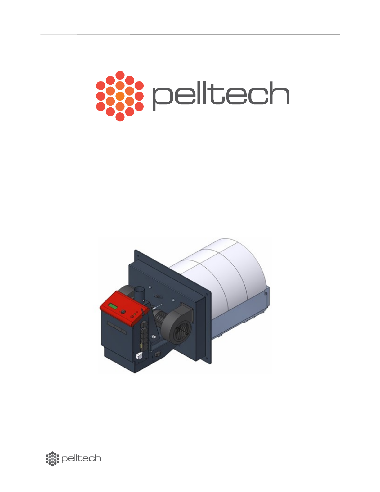
PV700a / PV1000a pellet burners
p 1/ 59
PV700a/PV1000a pellet burners
User manual
DK9401B1
DK9401B1 www.pelltech.eu
Page 2

PV700a / PV1000a pellet burners
p 2/ 59
Contents
Safety precautions ......................................................................................................................................... 4
Warnings ....................................................................................................................................................... 4
Notice ............................................................................................................................................................ 4
Set of components ........................................................................................................................................ 7
1 General description ............................................................................................................................... 8
1.1 Safety devices .............................................................................................................................. 12
1.2 Pellets .......................................................................................................................................... 13
2 Installation ........................................................................................................................................... 13
2.1 Prerequisites to boiler and boiler room ...................................................................................... 13
2.2 Burner installation ....................................................................................................................... 15
2.3 Water sprinkler ............................................................................................................................ 24
2.4 External auger ............................................................................................................................. 24
2.5 Pellet storage ............................................................................................................................... 25
2.6 Electrical connections .................................................................................................................. 25
2.7 Initial start-up .............................................................................................................................. 27
3 Optional components .......................................................................................................................... 27
3.1 GSM modem ................................................................................................................................ 27
3.2 Error output ................................................................................................................................. 28
3.3 Flue gas fan .................................................................................................................................. 29
3.4 Oxygen amount sensor ................................................................................................................ 30
3.5 Ash removal system .................................................................................................................... 31
3.6 External boiler temperature sensor ............................................................................................ 31
4 Operation and service ......................................................................................................................... 32
4.1 User interface .............................................................................................................................. 32
4.2 Starting and stopping .................................................................................................................. 33
4.3 Fuel refilling ................................................................................................................................. 33
4.4 Statuses and parameters ............................................................................................................. 33
4.5 Output power levels .................................................................................................................... 40
4.6 Main menu and settings .............................................................................................................. 40
DK9401B1 www.pelltech.eu
Page 3

PV700a / PV1000a pellet burners
p 3/ 59
4.7 Regular maintenance .................................................................................................................. 43
5 Problems and solutions ....................................................................................................................... 43
6 Burner status change logic .................................................................................................................. 45
7 Annex 1 Electrical diagrams ................................................................................................................ 47
8 Annex 2 – Controller board ................................................................................................................. 50
9 Annex 3 Control unit ........................................................................................................................... 53
10 Annex 4 Table of parameters .......................................................................................................... 55
11 Annex 5 Table of languages ............................................................................................................. 57
Warranty ..................................................................................................................................................... 58
DK9401B1 www.pelltech.eu
Page 4

PV700a / PV1000a pellet burners
p 4/ 59
Safety precautions
Do not start the burner before it is connected to the boiler and the boiler is connected to the
chimney.
It is recommended to wear a respirator while handling pellets.
The boiler room where the burner is installed must fulfil all rules and recommendations given by
authorities.
All electrical connections must be done by trained professionals.
No flammable materials must be stored near the burner.
Warnings
Changing the construction of the burner without written permission from the manufacturer is
forbidden.
Use only spare parts provided or approved by the manufacturer in order to avoid any damage to
the burner and dangers resulting from it.
Welding is allowed only after disconnecting the burner from electric supply. The circuit board
must be removed from the burner.
Do not open any boiler door while the burner is in operation.
Notice
Manufacturer of burners has right to make changes in construction of burner and its firmware.
Burner corresponds to following directives and standards:
Directive 2004/108/EC
Directive 2006/95/EC
Directive 2001/95/EC
Directive 2006/42/EC
EN 15270 2008
EN 230 2005
EN 60370-2-5 2002
DK9401B1 www.pelltech.eu
Page 5
PV700a / PV1000a pellet burners
p 5/ 59
Pellet burner PV 700a
No
Year of production
2014
Electrical supply
230V
Max heat input
20kW
Emission class
5
Noice emission
52dB
Power consumption at stand-by
7 W
Manufacturer: Pelltech OÜ, Sära tee 3, Peetri, Estonia
Pellet burner PV 1000a
No
Year of production
2014 Electrical supply
230V
Max heat input
1000kw
Emission class
5
Noice emission
52dB
Power consumption at stand-by
7 W
Manufacturer: Pelltech OÜ, Sära tee 3, Peetri, Estonia
DK9401B1 www.pelltech.eu
Page 6
PV700a / PV1000a pellet burners
p 6/ 59
DK9401B1 www.pelltech.eu
Page 7
PV700a / PV1000a pellet burners
p 7/ 59
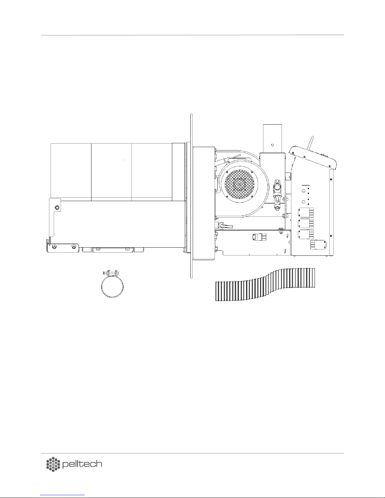
1. Burner with burning chamber
2. Bracket 2 pcs
3. Hose 76mm
3 1 2
Set of components
DK9401B1 www.pelltech.eu
Page 8
PV700a / PV1000a pellet burners
p 8/ 59
Parameter
Unit
PV700a
PV1000a
L total length
mm
1190
1306
L1 housing length
mm
592
624
L2 burning chamber length
mm
590
682
⌀D1feeder auger’s tube diameter
mm
80
80
Pellet inlet tube diameter
mm
76
76
H total height
mm
598
621
H1 burning chamber height
mm
451
545
W burner housing width
mm
606
706
W1 burning chamber width
mm
528
614
Required chimney diameter
mm
300
350
Mass net/bruto
kg
150/185
230/280
Max amount of flue gases
M3/h
1800
2500
Max fuel consumption
kg/h
150
213
Maximum/nominal power
kW
700
1000
Minimum power
kW
200
250
Hold flame power
kW
40
60
Noise level
dB
58
58
Emission class EN 15279
-
5
5
Operating temperature
Co
-10…40
-10…40
Supply voltage
VAC
3x380
3x380
El power at ignition
W
1100
2100
El power, average
W
370
480
El power at standby
W
20
20
Table 1 Technical data of burner
1 General description
PV700a and PV1000a are burners of wooden pellets (sawdust granules) that are intended to use in
different boiler houses. Only wooden pellets with 6 or 8mm diameter can be used to run burners. You
cannot use any other form of fuel but pellets to run the burner. Unique design of burners’ burning
chambers allows to burn also industrial pellets. The construction of the burners allows them to be used
with different boilers: liquid fuel, solid fuel and universal boilers. The burner is connected to the boiler
by using a connection plate.
The burner is equipped with a safety thermostat, a melting hose, temperature sensor, sprinkler system
with pressure switch and auxiliary battery for protection against back-burning. Main technical data are
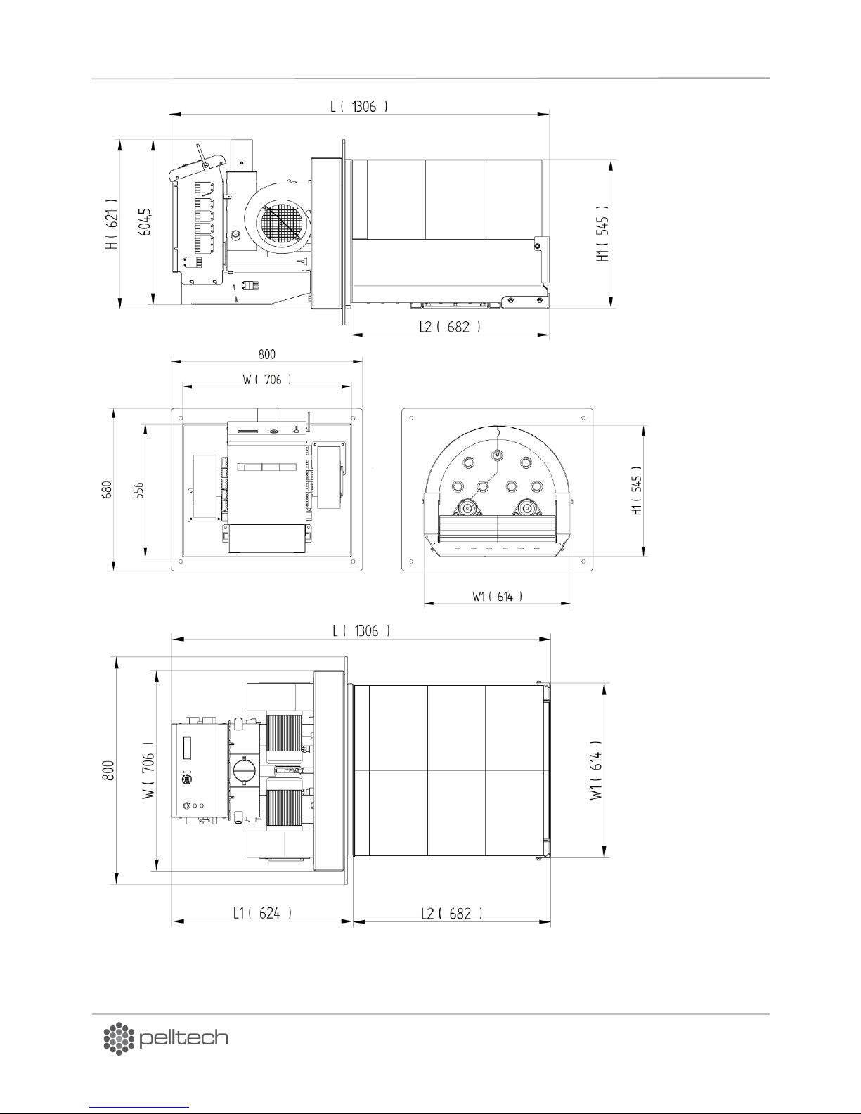
given in Table 1 and Figure 1.
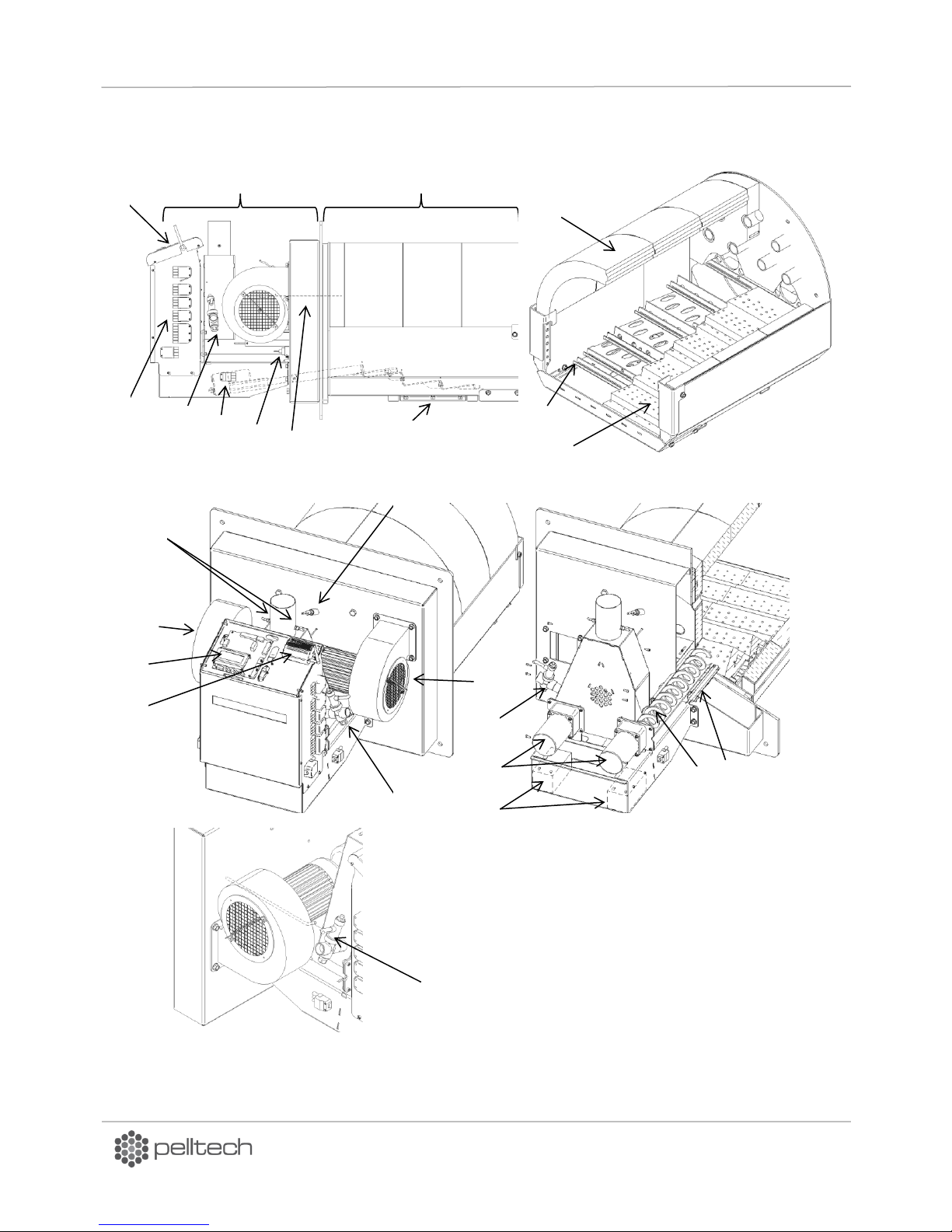
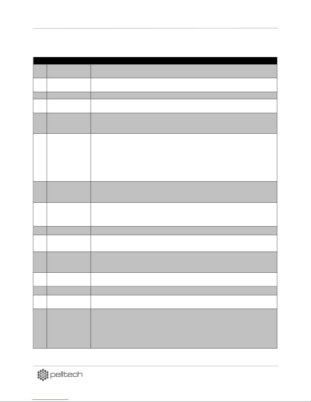
Main components of the burner and their locations are depicted in Figure 2 and described in Table 2 .
DK9401B1 www.pelltech.eu
Page 9
PV700a / PV1000a pellet burners
p 9/ 59
Figure 1 Main measurements of PV1000 burner
DK9401B1 www.pelltech.eu
Page 10
PV700a / PV1000a pellet burners
p 10/ 59
14
15
13 5 15 1 2 3 4 5 6 7 16
17 5 18
20
7
12
11
10 9 8
19
21
Figure 2 Main components
DK9401B1 www.pelltech.eu
Page 11
PV700a / PV1000a pellet burners
p 11/ 59
No
Name
Description
1
Burning
chamber
The part of the burner that is inside the boiler and where pellets are burnt.
2
Burner body
The part of the burner that is outside the boiler and where burner’s control and
pellets supply takes place.
3
User interface
Control board with screen, navigation buttons and indication lights.
4
Control unit
Electrical- and control panel what contains inverters, fuses, relays, main
controller board and other control devices
5
Water sprinkler
Sprinkler system will spray water to extinguish the fire in feeder’s tube in case
of back burning. The sprinkler system is activated only when the temperature
of feeder auger rises dangerously high.
6
Grate cleaning
motor
Linear motor moves the grates in burning chamber and pushes ash out from
burning chamber. This cleaning cycle is made periodically. The interval between
cleaning cycles can be controlled by PAR48. In each cleaning cycle, the linear
motor pulls grates back then pushes the grates completely out. The linear
motor has 75mm stroke and end switches for stop. Linear motor current limit
can be set by PAR47. Linear motor is protected by fuse F10 what is installed on
the controller board (board version BBB v2.1).
7
Igniter
Igniter´s purpose is to ignite loaded fuel making the burning process start.
Igniter is installed on the burner together with igniter holding pipe. PV700 has
2 igniters and PV1000 4 igniters.
8
Brick
temperature
sensor
A sensor to adjust bricks’ heat up speed according to temperature rise. Brick
temperature rise speed control helps to reduce thermal stress of bricks and
prolong their lifetime.
9
Cleaning hatch
Hatch below burning chamber to ease the removal of ash under the grates.
10
Grates support
frame
Holds moving and stationary grates in correct position.
11
Grates
Burning of pellets takes place on the cast iron grates. Air needed for burning is
blown to burning chamber via holes with different size. Burner has moving and
fixated grates. Moving grates move periodically to clean the burning chamber.
12
Fire bricks
Burning chamber is surrounded with heat resistant from up and sides. Bricks
are necessary for proper airflow and combustion.
13
Flame sensor
Photocell´s purpose is to recognize flame in the burning chamber.
14
Level sensor
Optical fuel level sensors recognize the fuel level in the vertical pipe. Fuel is
recognized when pellets pass the optical beam between sensors.
15
Combustion air
fans
Left – primary
Right –
Primary fan blows main burning air needed for ignition, burning and
gasification of the fuel.
Secondary fan blows air through burning chamber back-wall and holds burning
Table 2 List of main components
DK9401B1 www.pelltech.eu
Page 12

PV700a / PV1000a pellet burners
p 12/ 59
secondary fan
quality and optimal flue gas content. To control the burning procedure oxygen
sensor (optional) for fan’s speed regulation is used.
Both fans rotation speed is measured by sensor, installed near the impeller
axle. The sensor is reading magnetic field changes caused by magnet installed
on the impeller axle.
16
Controller board
Controller board controls the burner´s burning process, by calculating fuel
amount also feeder and auger work during burning process. Depending on the
input signals from the sensors, controller makes necessary changes to the
output states to maximize burning efficiency. Controller has a single control
board.
17
GSM modem
(optional)
A GSM modem enables burner to send SMS messages with various information
of burner´s operating states (errors). GSM modem is located on control unit.
18
Feeder auger
motors
Internal feeders are used to deliver correct amount of fuel into burning
chamber. Delivered fuel amount is regulated by periodical work of feeder gear
motors.
24V DC motors are supplied from backup battery to empty feeder tubes in case
of power failure.
19
Battery
When there is no power from the main power supply then the burner is
operating on battery power. PV1000 uses two 12V 3,4 Ah batteries. Because
the battery is a safety element, the burner checks batteries condition and does
not start the next working cycle if the batteries voltage is too low.
20
Internal feeder
screw
Hollow spiral connected to feeder motor to transport pellets into burning
chamber. Screw is not tightened to motor, but has small slack. It lowers the
mechanical stress and expands gear motor lifetime.
21
Pressure sensor
connection
Metal tube to connect pressure sensor input. Pressure sensor measures
draught in burning chamber and enables the controller to regulate flue gas fan
speed.
1.1 Safety devices
The back-burning is the biggest danger risk at burners working procedure. Back-burning appears when
usual pressure or draught conditions have changed in boiler’s combustion chamber. There are several
reasons for such changes.
In order to secure operational and fire safety the PV700a/PV1000a burners are equipped with following
safety devices:
Back up batteries. Enable to finish safely burning procedure in normal conditions or during
unexpected black out in mains supply.
Melting hose. The external auger is connected to the burner with a special hose (∅ 76mm), which is
made from easily melting polyurethane material that interrupts when back-burning takes place.
Such measurement avoids entrance of the flame from burner into external auger and pellets
container.
Thermostatic sprinkler valve. Enables to extinguish the fire in feeder’s augers tube by spraying
water into it, when burner is overheated due to possible back-burning or any other reason.
DK9401B1 www.pelltech.eu
Page 13
PV700a / PV1000a pellet burners
p 13/ 59
Premium pellets
Industrial pellets
Raw material
Sawdust, cutter shavings, stem
wood
Forest, plantation and other
virgin wood, chemically
untreated wood residues
Calorific value
4700-5100 kWh/ton
ca 4700 kWh/ton
Volume weight
ca 650-670 kg/m3
>675 kg/ m3
Volume of 1 ton pellets
1.5-1.6 m3
ca 1.5 m3
Diameter
6-10 mm
6-12 mm
Length
3-5 x diameter
ca 4mm
Moisture content
8-10 %
ca 5 %
Ash content
ca 0,5%
ca 2%
To replace 1000 l light oil
ca 2 tons or 3 m3
ca 2 tons or 3 m3
Table 3 Pellets’ overview
Fire safety water pressure control switch (pressostat). Enables to keep necessary water pressure in
water reservoir and to ensure with that successful extinguishing procedure when needed.
Pressostat switch allows starting the burner only if water supply is present and pressure exists.
1.2 Pellets
Wooden pellets or saw dust granules are concentrated and homogenized wooden fuel. Pellets are
pressed with high temperature. No extra materials are added, pellets are held together by a natural
ingredient found in wood – lignin. Pellets are neutral, renewable fuel. Its burning doesn’t spoil CO2
balance in the atmosphere. Not only premium but also the industrial pellets can be used in
PV700/1000a. Pellets must be stored in a dry and ventilated room. Table 3 provides an overview of pellet
properties and threshold values.
2 Installation
2.1 Prerequisites to boiler and boiler room
In order to install the burner, the boiler must meet to the following requirements:
It is recommended to use three pass boilers.
The construction of the boiler must make it possible to open the door of the boiler with the burner
connected and removing ash from the furnace. If the door of the boiler is too narrow for opening it
with the burner, then extra hinges must be mounted.
If there is not sufficient (less than 5Pa) negative pressure in the furnace, a flue gas fan should be
installed to improve the movement of the exhaust gases.
The boiler must be installed into boiler’s room in a way that there is enough space for cleaning the
burner, the boiler, the smoke pipe and removing the ash.
The burning chamber must not touch the bottom of the boilers furnace (min 10 cm distance needed).
DK9401B1 www.pelltech.eu
Page 14
PV700a / PV1000a pellet burners
p 14/ 59
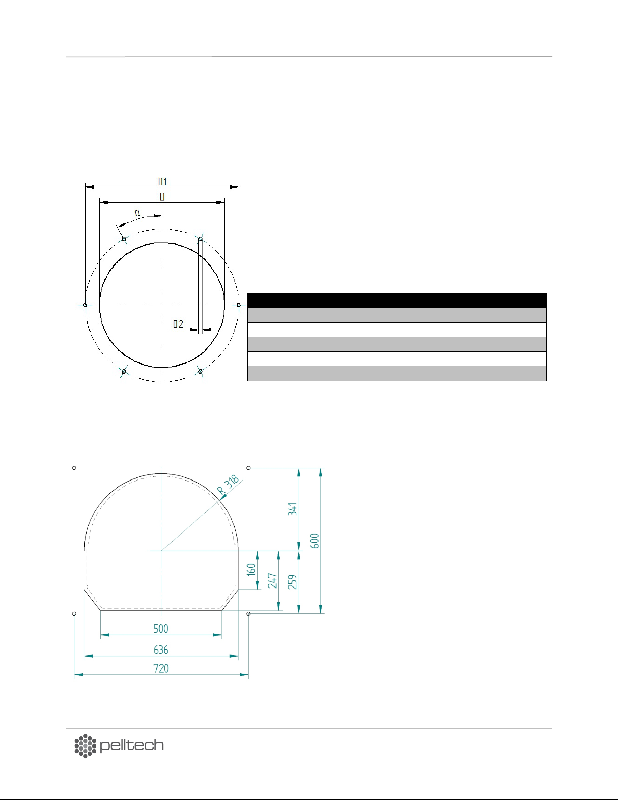
Dimension
Unit
Value
⌀D hole for burning chamber neck
mm
400
⌀D1 flange bolt ring diameter
mm
490
⌀D2 bolt holes
mm
6 x 13
Bolt hole offset angle
deg
30
Angle between bolt holes
deg
60
Figure 3 Boiler door mounting opening
Figure 4 Contour of cutting
The boiler room where the burner is installed must fulfill all rules and recommendations given by
local authorities.
Boiler room must provide constant air supply of 1500 m³ per hour (ca. 1600 cm
2
air inlet opening).
In order to mount the burner to the boiler door, it must have mounting holes. See Figure 3 .
Notice! If the burner is installed to the boiler, the door’s or the installation flange´s thickness should be
8-14mm.
Cutting contour of hole to be cut to boilers door in order to install PV1000 burner.
DK9401B1 www.pelltech.eu
Page 15
PV700a / PV1000a pellet burners
p 15/ 59
Mount the burning chamber on the
inner side of the boiler door.
Double hinges
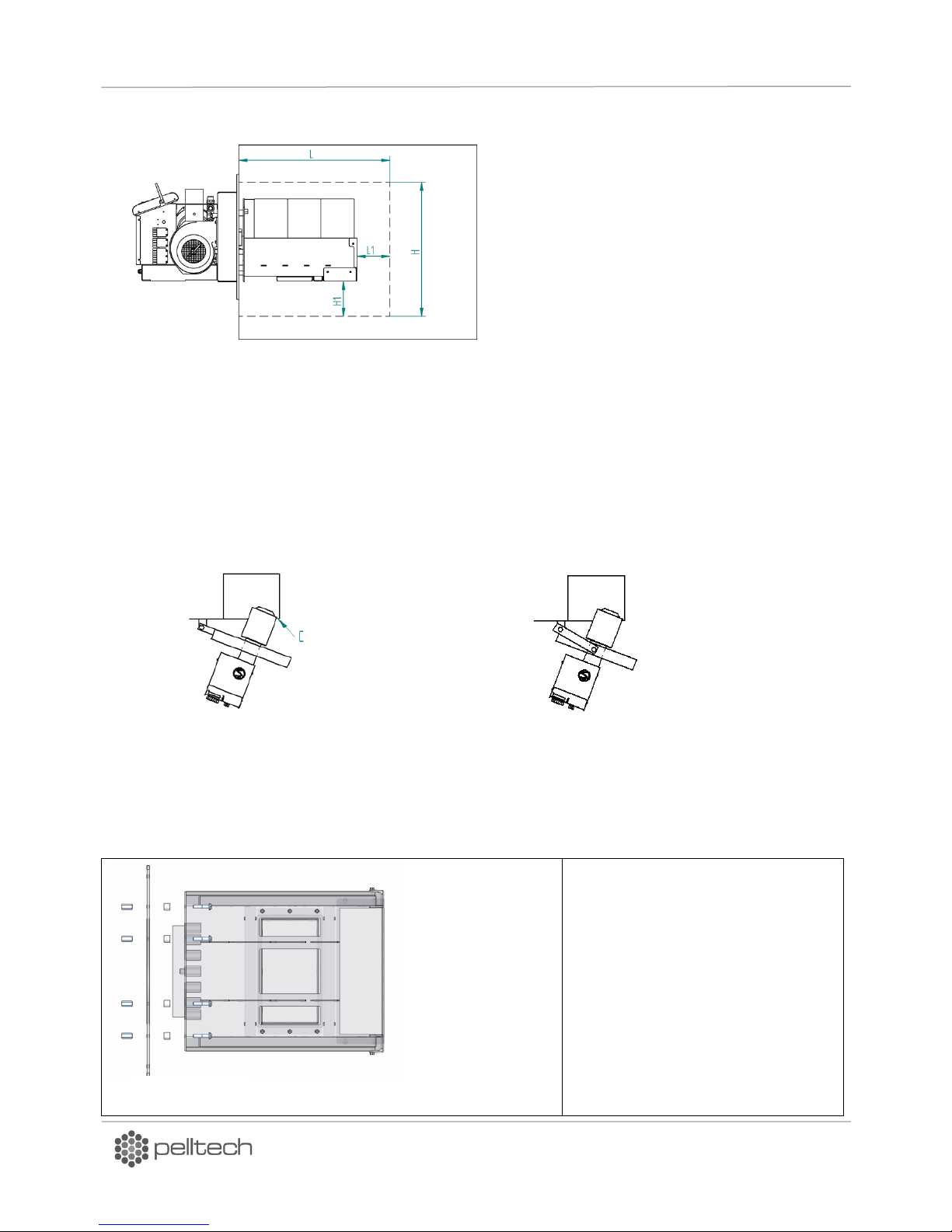
Boiler’s firebox depth L must be at least 2,5
times longer than the length of burner’s
burning chamber. Thus minimal length of
the firebox L for PV700 has to be 1500 mm
and for PV1000 1800mm. The height of
firebox must leave at least 100 mm space
(H1) for ash below burning chamber.
Minimum dimensions: L1 ≥700mm; H
≥650mm. See Figure 5.
Figure 5 Firebox depth
Figure 6 Burner has to
reach off from boiler
Figure 7
Pellet burners need regular cleaning and therefore boiler construction must allow easy opening of
boiler’s door without removing the burner. The minimum size of opening in boiler’s door depends on the
position of door hinges. Figure 6 below illustrates the situation. Point C is the critical point.
In order to keep door width minimum and boiler’s door opening small, a double hinge solution
can be used. As double hinges add another degree of moving-freedom, door must be fastened on both
sides. Slide-out doors with guide rails is also an option.
2.2 Burner installation
Burners are delivered to customer in fully put together. Before mounting the burner to boiler it has to be
disassembled i.e. bricks have to be removed and burning chamber separated from burner and air box.
DK9401B1 www.pelltech.eu
Page 16
PV700a / PV1000a pellet burners
p 16/ 59
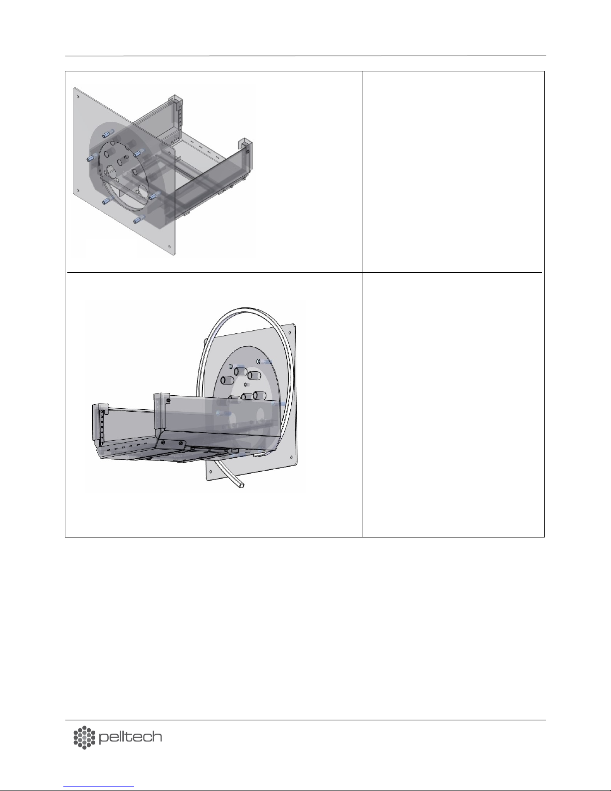
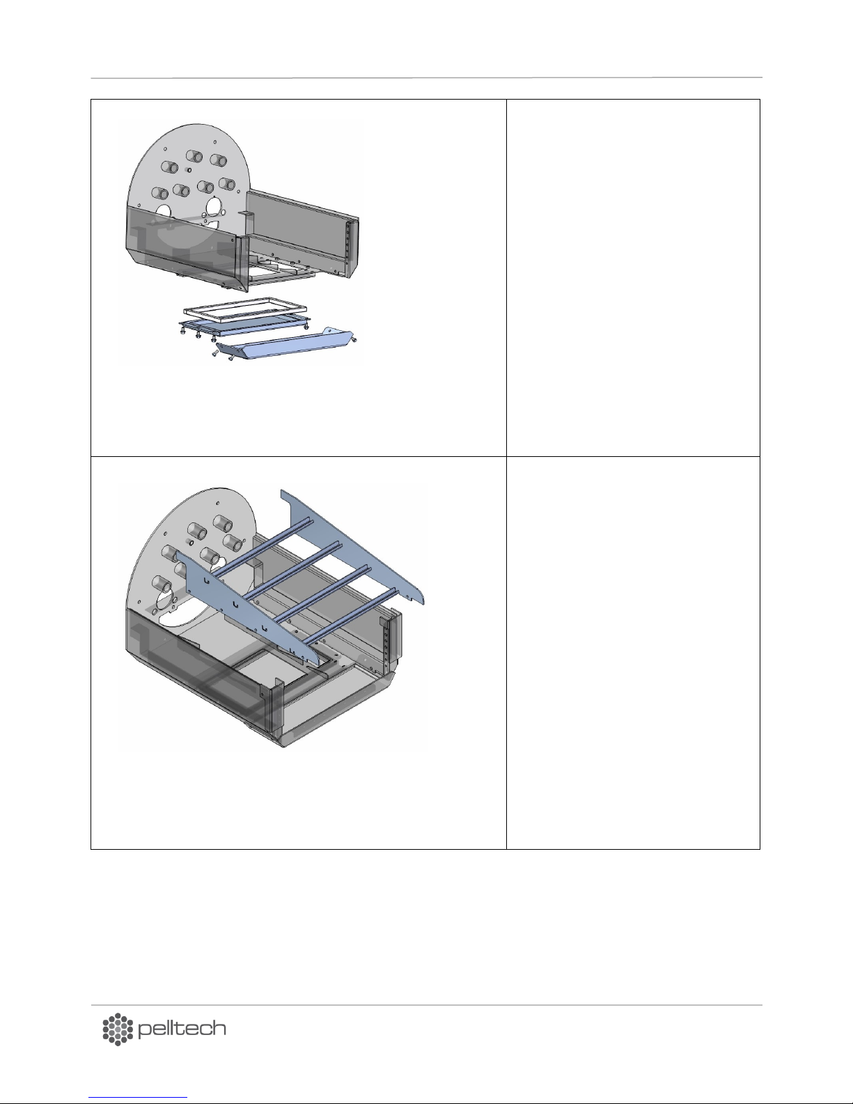
Figure 8
Install the insulation rope between
the burning chamber and the boiler
door. The rope must be installed
near the outer perimeter of the
burning chambers back wall.
Figure 9
Use 6 M12x60mm bolts, spacers
and distance nuts respective to
the bolts.
DK9401B1 www.pelltech.eu
Page 17
PV700a / PV1000a pellet burners
p 17/ 59
Connect the static grate holders with
the side stone holders separately and
install them together into the burning
chamber as a frame. Fix them with
M8x16mm bolts to the burning
chamber.
Figure 10
Figure 11
Grate holders installation
Install the burning chambers
bottom panel (15x15mm
insulation rope must be inserted
to the slot in the panel) with 6
M8x16mm bolts.
Install the burning chambers
front panel (heat shield), use
M8x16mm bolts.
DK9401B1 www.pelltech.eu
Page 18
PV700a / PV1000a pellet burners
p 18/ 59
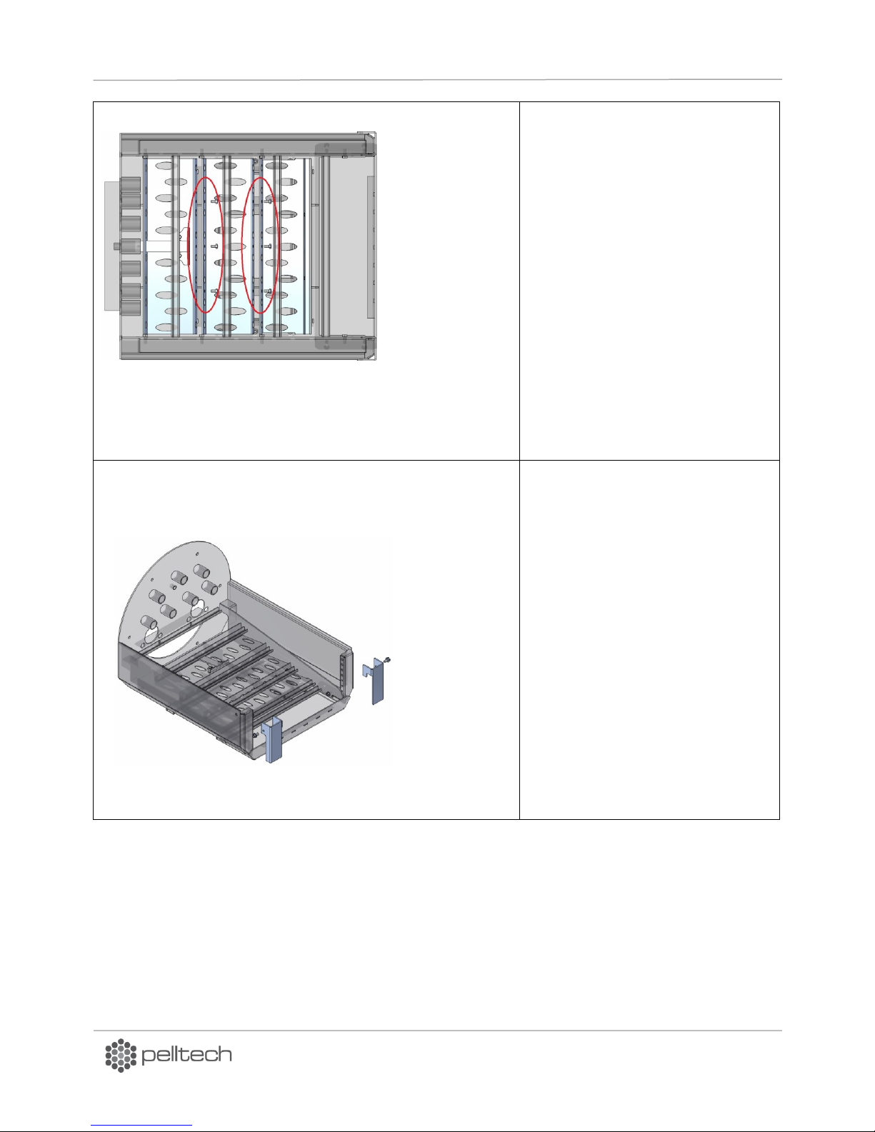
Connect the moving grate holders
with M6x12mm bolts.
Figure 12
Figure 13
Install the burning chamber’s front
brick holders, use M8x16mm bolts.
DK9401B1 www.pelltech.eu
Page 19
PV700a / PV1000a pellet burners
p 19/ 59
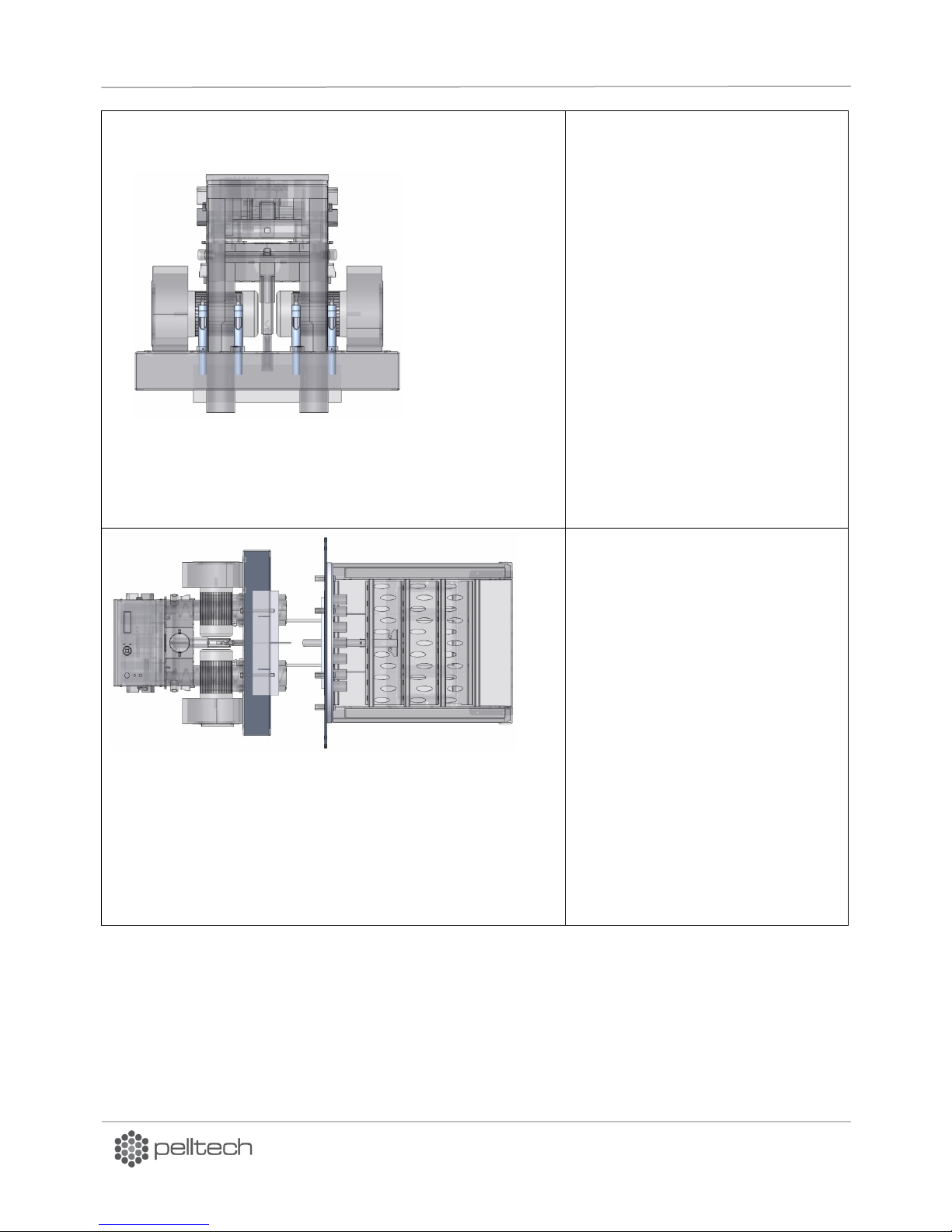
Release the igniter tube screws and
while inside the holders pull the tubes
out about half of the total length.
Move the air separator to its correct
position (according to the boiler door
thickness) and fix it with screws.
Figure 14
Figure 15
DK9401B1 www.pelltech.eu
Page 20
PV700a / PV1000a pellet burners
p 20/ 59
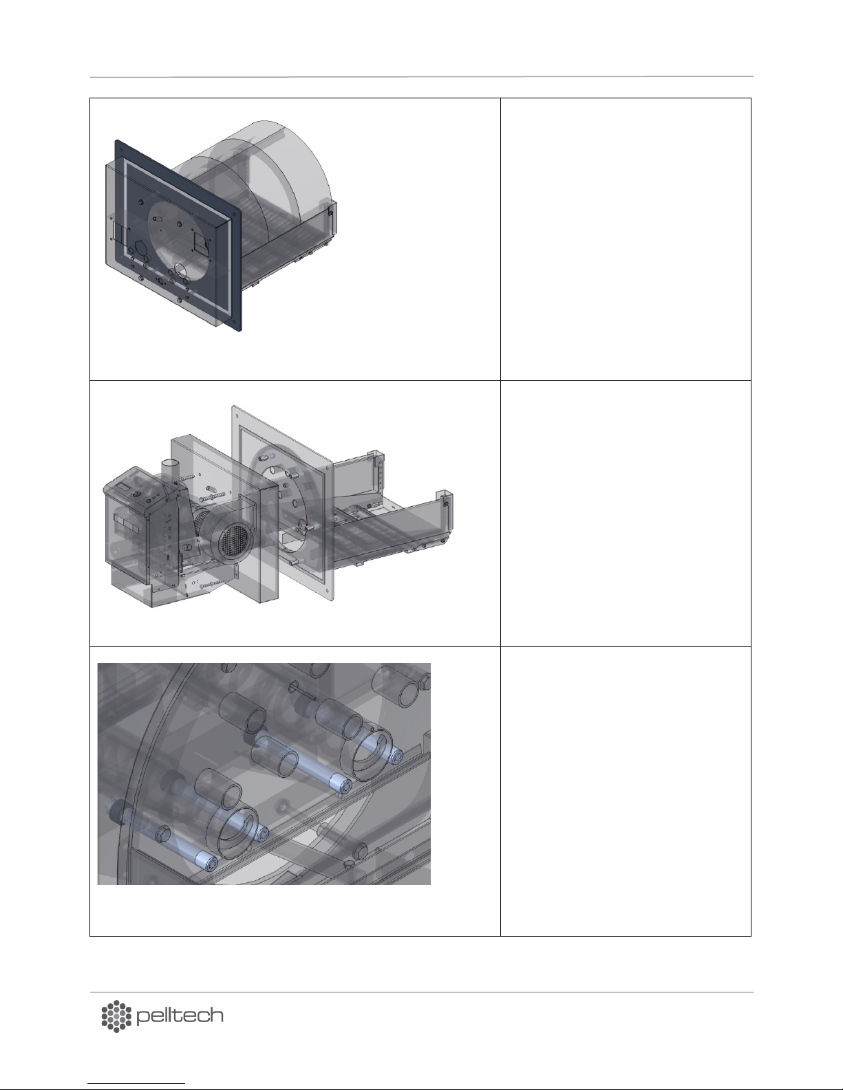
Install the ceramic sealing strips on
the boiler door. Fix them temporarily
in position with any ordinary
cellophane tape (scotch).
Cut away the excessive sealing on the
perimeter of the air chamber.
Mount the burner’s housing on the
boiler door, using 4 M12x70mm bolts
and respective washers.
Push the igniter tubes through the
burning chambers back wall and fix
them in position with M4 screws.
Figure 18
Figure 17
Figure 16
DK9401B1 www.pelltech.eu
Page 21
PV700a / PV1000a pellet burners
p 21/ 59
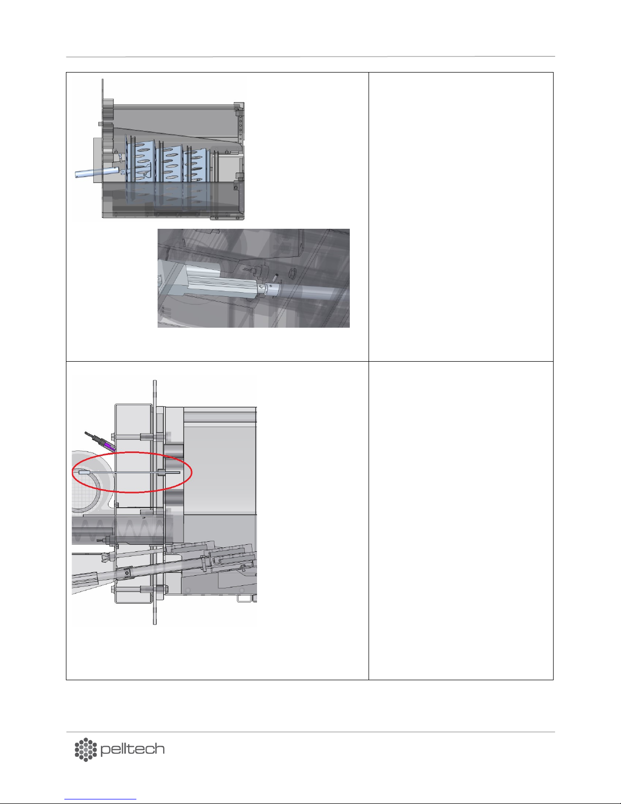
Connect the linear motor with the
moving grate holder. Use 27x2,5mm
pipe (length 240mm), M8x45mm bolt
for the burning chamber side and a
M6x25 socket set screw (DIN914 45H)
on the linear motor side.
Push the stone temperature sensor
through the hole in the burner body
and the pipe on the burning
chambers back wall, isolate it from
the air flow (accessible from the
burning chamber side) with ceramic
sealing to prevent cold air from
tampering with the measurements.
Figure 20
Figure 19
DK9401B1 www.pelltech.eu
Page 22
PV700a / PV1000a pellet burners
p 22/ 59
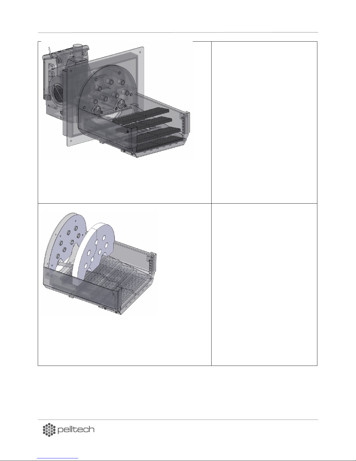
Install the 2 lower position grates .
Install the 8 middle position grates
with 5mm holes .
Install the 8 higher position grates
with 7mm holes.
Install the ceramic seal on the back
wall of the burning chamber.
Install the back wall stones on the
burning chambers back wall.
Caution! Be careful not to damage
the temperature sensor!
Push the stone temperature sensor
into the opening in the back wall
stone.
Figure 21
Figure 22
DK9401B1 www.pelltech.eu
Page 23
PV700a / PV1000a pellet burners
p 23/ 59
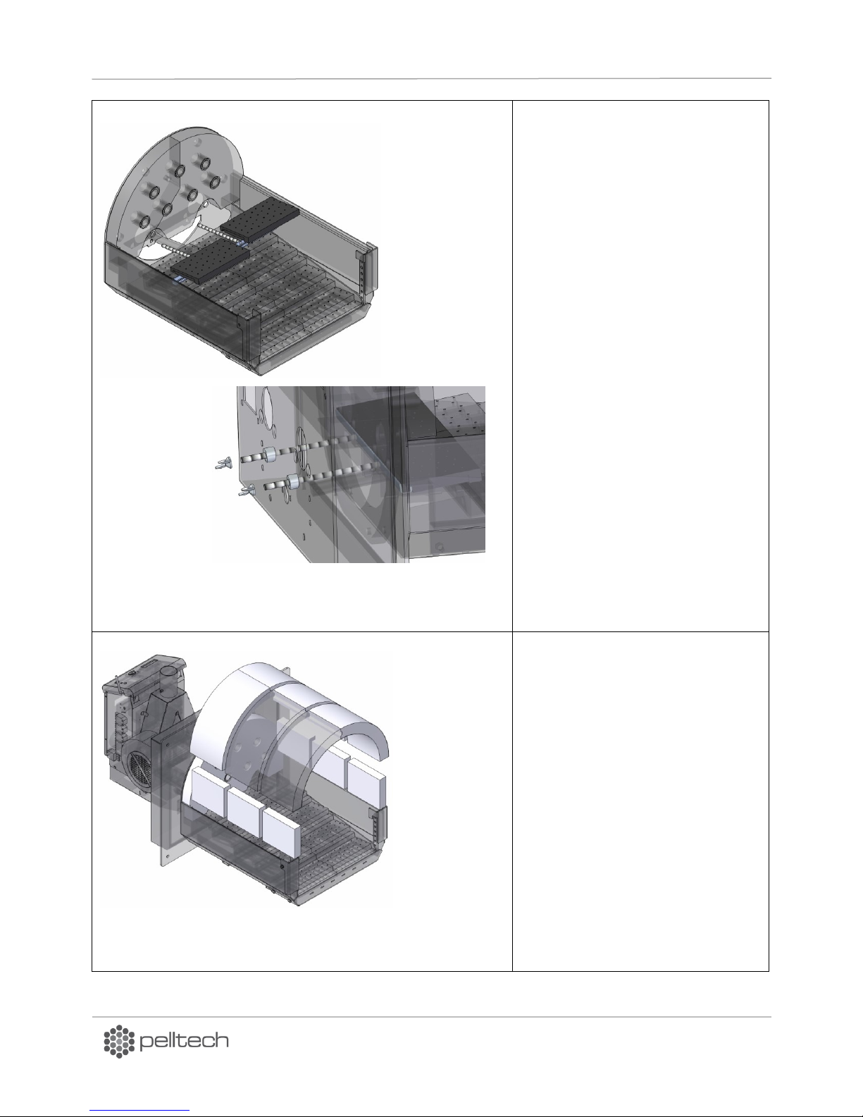
Install the upper grate holder and 2
upper grates. Fix the holder with M10
wing nuts.
Install the 6 side bricks.
Install the 6 arc-stones.
Notice! The arc-stones are numbered;
they must be installed as pairs!
Figure 23
Figure 24
DK9401B1 www.pelltech.eu
Page 24
PV700a / PV1000a pellet burners
p 24/ 59
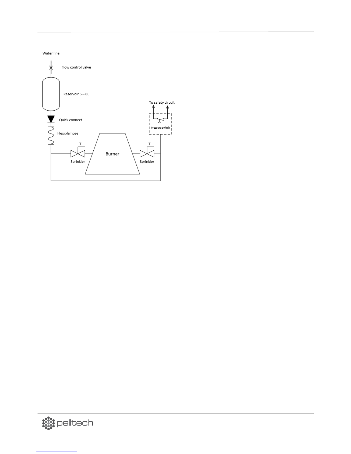
Principal chart of water sprinkler installation is
depicted in Figure 25. Water sprinkler is main
safety element against back-burning. It is
strongly recommended to install sprinkler
system. Pressure switch allows starting the
burner only if water supply is present. If no
water is available on installation site, reservoir
can be filled manually. In this case, pressure
switch is not connected to safety circuit as there
is no pressure in water system.
In case of back-burning, sprinklers will open and
fire is extinguished in feeder tubes. Flow control
valve limits the amount of water flowing into
burner after the reservoir is emptied. The
burning chamber must be cleaned from wet ash
and pellets before turning the burner back on
again.
2.3 Water sprinkler
Figure 25 Water sprinkler installation
2.4 External auger
The external auger transports pellets from the pellet container to the burner. The burner controls the
work of the external auger. The auger is connected to the burner with a special hose (∅ 76mm), which is
made from easily melting material- polyurethane that acts as a safety measure against back-burning.
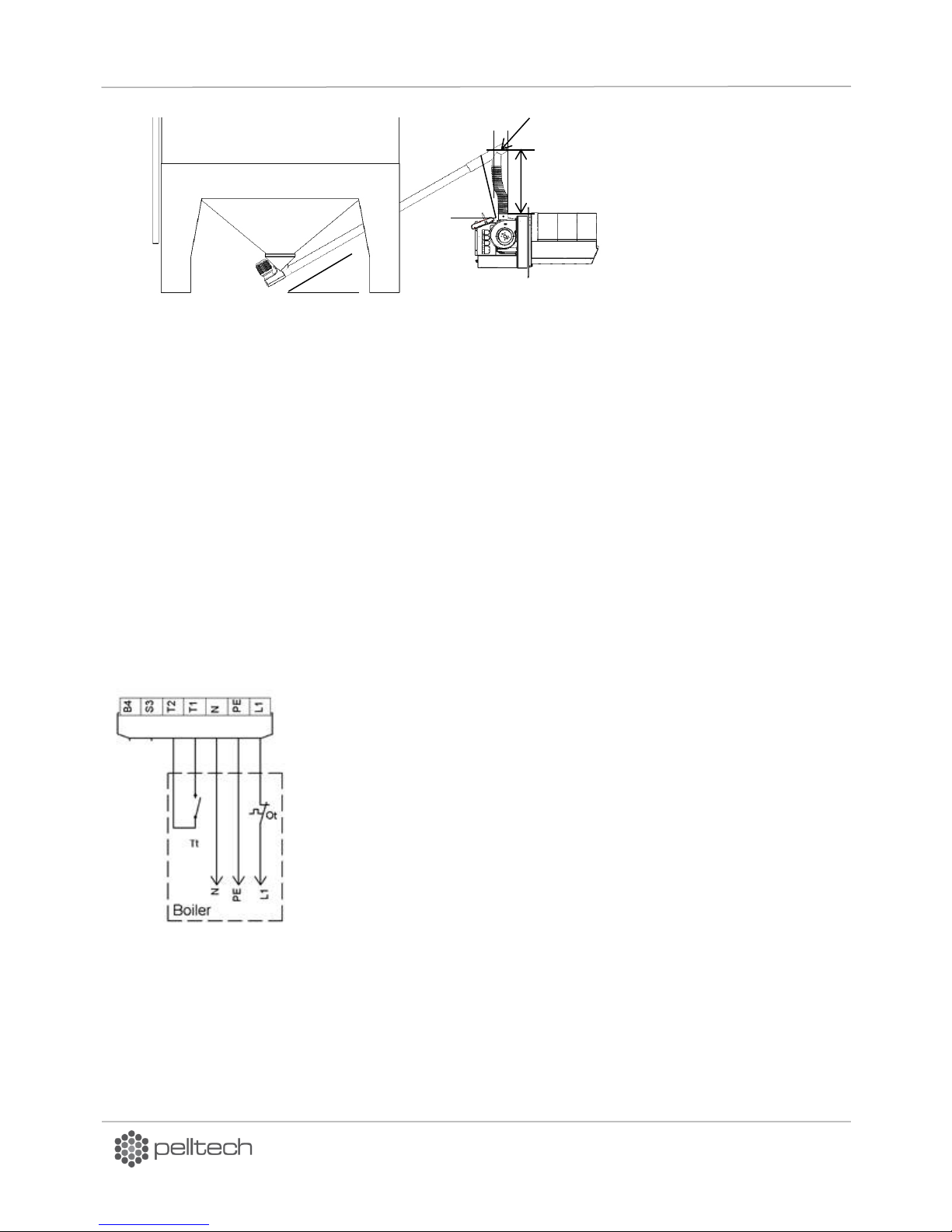
PV1000a pellet burner´s fuel consumption at full power is about 208-222 kg of pellets per hour ( 3,3-3,7
kg per minute ). External auger´s productivity for PV700/PC1000 must be at least 270kg of pellets per
hour. The auger can be fixed to the storage or a ceiling depending on the conditions at the installation
site.
Critical requirements for external auger installation:
The raising angle of the auger must not exceed 45°
The end of the exit tube of the auger and the input of the burner must not be aligned. The
recommended minimal horizontal distance is ca 20cm.
The distance between the input of the burner and the exit tube of the auger must be at least
60cm vertically – recommended distance is 80-200cm.
Hose between auger and burner must be tight, otherwise pellets will block the auger. Falling
angle must me between 65° and 85°.
All critical requirements for installation of external auger are depicted in Figure 26 .
DK9401B1 www.pelltech.eu
Page 25
PV700a / PV1000a pellet burners
p 25/ 59
>60cm
>65
o
max45
o
20cm
Figure 26 External auger installation
2.5 Pellet storage
Pellets must be stored in a dry and ventilated room that is separated from the boiler room. A tailor made
storage (silo) is recommended. All safety regulation must be taken into consideration according to the
local laws. It is recommended to wear a respirator when handling pellets. Refilling must be carried out
before the storage runs empty.
2.6 Electrical connections
Following connections must be done by the electrical installer:
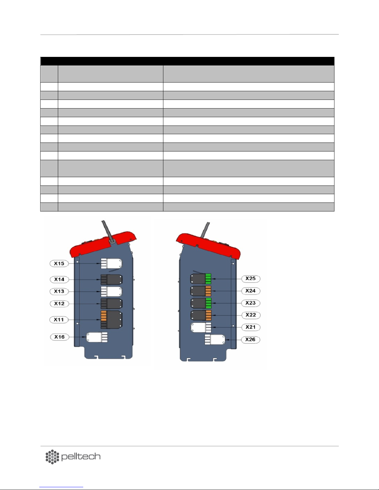
1-phase supply and boiler’s thermostat to socket X11 . See Figure 27.
3-phase supply to socket X12
External auger to socket X14
Names and marking of sockets is described on Table 4.
Figure 27 Connection of socket X11
DK9401B1 www.pelltech.eu
Page 26
PV700a / PV1000a pellet burners
p 26/ 59
No.
Name
Voltage, amps
X11
Control voltage, boiler’s
thermostat
230VAC, 3A
X12
Main power supply
3x380VAC 20A
X13
Safety circuit
230V
X14
External auger 1
3x380V 0,55kW 1,6A
X15
External auger 2
3x380V 0,55kW 1,6A
X16
Primary fan
3x230V 0,18kW/0,37kW (PV700/PV1000)
X17
Igniters
2x500W 2x2,2A (PV1000)
X21
Flue gas fan
3x230V max 1,5kW
X20
Flue gas inverter
0...10V, 24V DC
X22
Modbus
24V DC
X23
Pt100/4..20mA sensors ( O2 and
boiler water)
24V DC
X24
Level sensors (silo1 and silo2)
24V DC
X25
Ash auger and scraper
230V 90W
X26
Secondary fan
3x230V 0,18kW/0,37kW (PV700/PV1000)
X27
Igniters
2x500W 2,2A (PV700, PV1000)
Figure 28 Connectors’ markings
Table 4 PV1000a connectors
DK9401B1 www.pelltech.eu
Page 27
PV700a / PV1000a pellet burners
p 27/ 59
Before inserting the SIM card to burner the following actions have to be done:
1. SIM card must by activated by the mobile operator.
2. PIN code request has to be switched out.
3. Check by using mobile phone that it is possible to send SMS with this SIM card.
4. In SIM card´s phonebook must be only the numbers, where to the messages from the burner
will be sent.
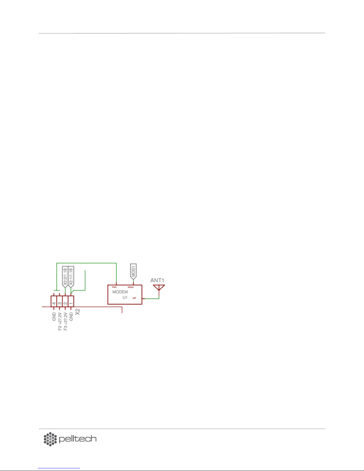
Figure 29 Modem connection
2.7 Initial start-up
Prior to the initial start-up of the burner make sure that:
The burner is connected to the boiler.
The boiler thermostat is installed and is functioning properly.
The feeding auger of the burner is installed and connected to the burner.
The smoke duct is connected to the chimney, the dampers for smoke gases are open and there is
sufficient draught. When the burner is operating, the negative pressure inside the furnace must stay
between 5-20 Pa.
Sprinkler system is connected and pressure switch connected to safety circuit (chapter 2.3).
Phase (L) and neutral (N) wires in power cable are connected properly.
3 Optional components
3.1 GSM modem
PV700a and PV1000a burners are ready to send burner’s error SMS messages up to 5 phone numbers.
When error occurs the modem will send list with history of errors and statuses before error. If list is very
long then so much information what has a room in message will be sent. Average length of one message
is 8 statuses or errors.
In order to send messages EP007 modem has to be connected to burners control board’s connector X2.
See Figure below. RS232 modem adapter cable has to be connected between modem’s connector
MOD1 and connector MOD1 what is located lower part of control board.
DK9401B1 www.pelltech.eu
Page 28
PV700a / PV1000a pellet burners
p 28/ 59
Red LED indicator
Modem status
Permanently on
Sending message (on-going call)
Fast interrupt sequence (period 0,5 s Ton 1s)
Net search/Not registered/ Turning off
Slow interrupt sequence (period 0,3s Ton 3 sec)
Registered full service
Permanently off
Device is turned off
PAR50 value
Description
1
Normaly open circuit (NO). Switches on when error appears.
2
Normaly closed circuit (NC). Switches off when error appears.
3
SWITCHED ON in IGNITING, HEAT UP, BURNING and HOLD FLAME statuses.
4
Not in use.
5
Not in use.
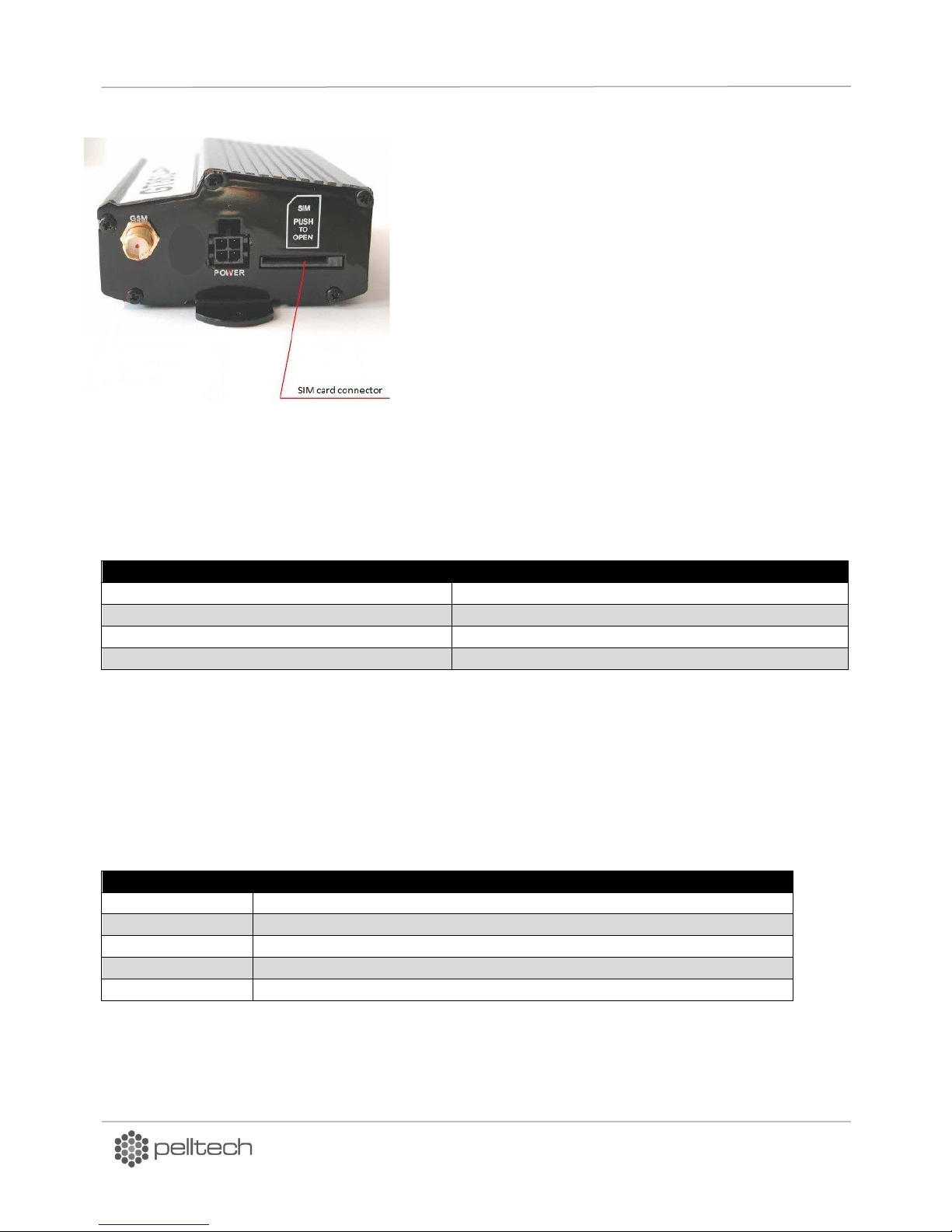
To insert the SIM card, the modem has to be
disconnected from supply mains. To insert the card
push it into a slot as long as its spring clicks and fixes
the card. See Figure 30. To remove card push it in as
long as spring clicks and pushes it out.
In order to activate SMS sending, in burners menu
PAR52 has to be changed. Value shows for how many
numbers the message will be sent. “0” means no
messages to be sent. “2” means that messages will be
sent to 2 first recipients in SIM card in order of phone
number insertion.
Figure 30 SIM card insertion
Modem has two indicators. Green one shows that modem is turned on. Red one shows modem
status. Modem’s statuses are described in Table 5.
Table 5 Modem statuses
3.2 Error output
PV700/PV1000 burner has built in error output what gives 230 VAC tension (NO) to 7-pole socket’s S3
connector or interrupts it (NC) if burner delivers any error message from elven (FLAME ERROR, BATTERY
EMPTY, IGN.ERROR etc). Device (motor, modem etc) up to 5A@230VAC can be connected to circuit.
PAR50 defines weather error output is closed or open during error appearance. Depending on NO or NC
selection values in PAR50 have to be changed.
DK9401B1 www.pelltech.eu
Page 29
PV700a / PV1000a pellet burners
p 29/ 59
3.3 Flue gas fan
The burner needs stable under-pressure in burning chamber for its correct operation. Simplest way to
assure this is to use the flue gas fan between boiler and chimney. With flue gas fan the burner can
control and hold constant under-pressure. In order to control flue gas the PAR60 value has to be set
to”2” ON. Selected flue gas fan must provide transmission of the maximum flue gas amount and exceed
the pressure provided by boiler, ash cyclone and chimney. The flue gas capacity for burned pellets can be
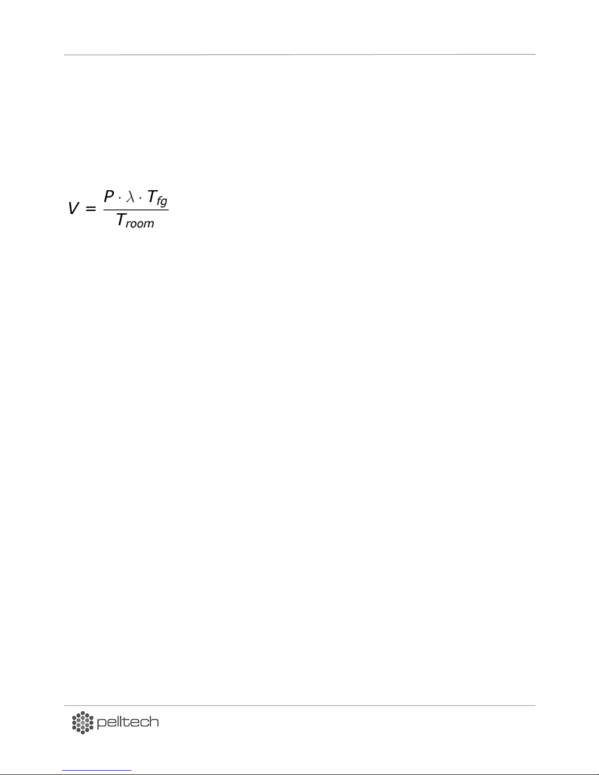
calculated by simplified formula.
V – Capacity range in m³/h
P – Burner max power in kW
Tfg – Flue gas absolute temperature in K
T
- Room absolute temperature in K
room
λ (lambda) – Excess air ratio
PV burners are designed to work at lambda values 1.2...1,5 - for calculations choose value of 1,5.
Flue gas fan must be installed between boiler and chimney. If ash cyclone is used then flue gas fan must
be installed between ash cyclone and chimney to avoid overpressure in cyclone and smoke leakage.
Burner setup
Depending on burner’s configuration (weather inverter included or not) the electrical connections may
be different. In case the frequency inverter has already been installed in factory to the burner, the flue
gas fan can be directly connected to the burner through connector Y8. Fan must be connected to burner
with 3-wire cable (3x1,5mm²). Internal inverter output is 3 x 230V. If flue gas fan motor is a three phase
motor (3 x 230/380V) then it has to be connected as triangle.
In case the burner has no inverter, the external inverter for flue gas fan can be used.
Inverter must be selected according to fan motor’s parameters and available power supply. The inverter
must be switched to sink logic (negative common).
To connect the external inverter with burner there is connector Y7 with 3 output signals:
• T1 - burner DC common (ground), must be connected with external inverter input common.
• S3 – inverters “run” command, must be connected with F (forward) pin on inverter input. Burner
will connect this pin to ground when fan must run.
• B4 – 0… 10V output for fan speed, must be connected with inverter analogue input.
Inverter setup
Inverter parameters are set up at factory for automatic control. To test flue gas fan manually:
1. Press Easy button on inverter
2. Press Dial button and change settings :
CN0d – “0” FN0D – “0” F174 – “0”
DK9401B1 www.pelltech.eu
Page 30
PV700a / PV1000a pellet burners
p 30/ 59
Parameter
Description
Unit
Value
No
Name
Def
Min
Max
PAR66
OXYGEN TYPE
0 – no sensor
1 – 4…20mA = 0…25% oxygen
2 – 4…20mA = 0…20% oxygen
- 0 0
2
PAR67
OXYGEN SET
Oxygen level set-point in flue gas
- 6 4
12
3 2 1
+mA
-mA
PT100 T8
+27.2V T6
GND B5
O2
X23
JP1
JP2
Heater
-mA/PT100 T7
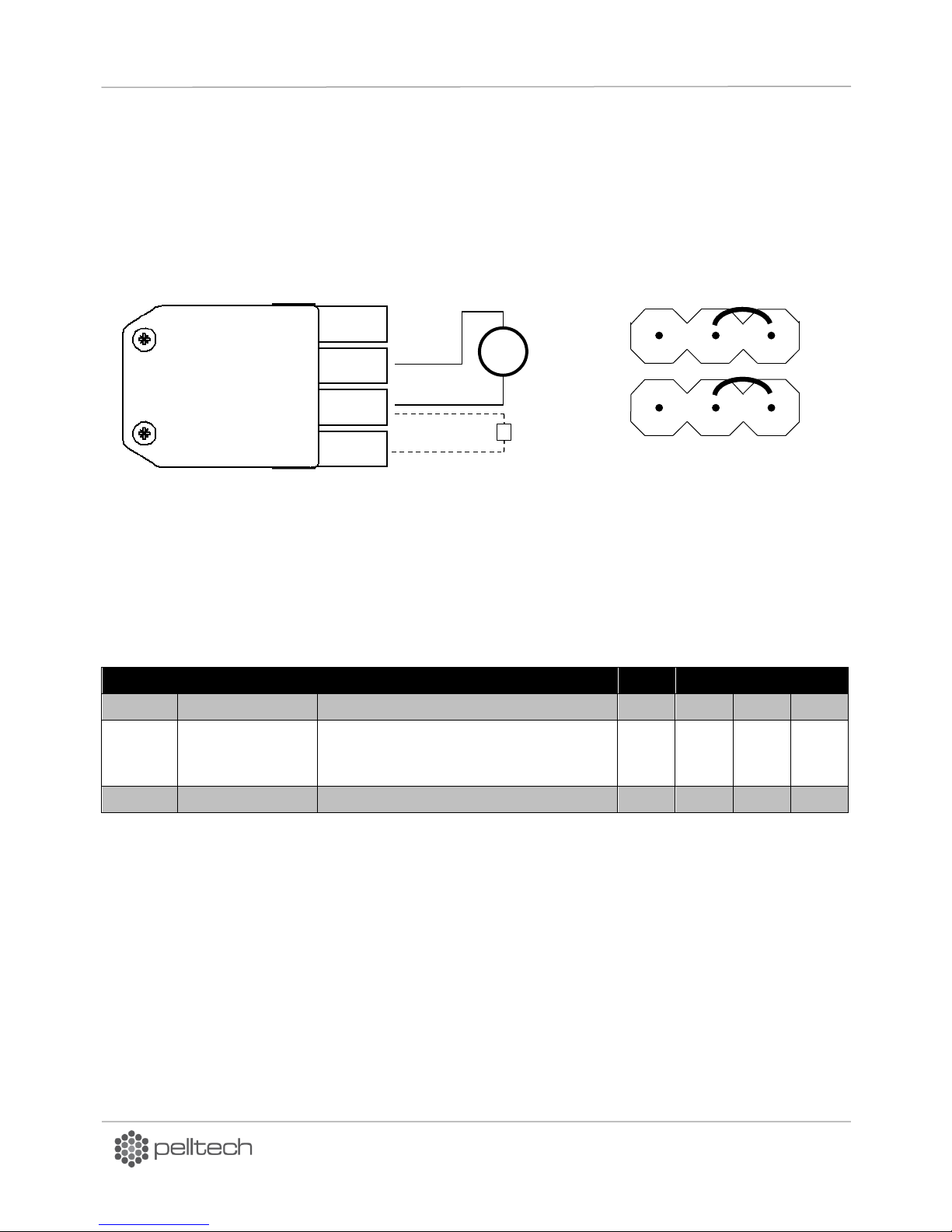
3.4 Oxygen amount sensor
Oxygen amount sensor (oxygen sensor) allows the burner to keep pre-set oxygen level in flue gas, what
increases the efficiency of the burning process. The oxygen sensor is connected to socket X23 as shown
on
Figure 31 .
If the sensor requires heater connection, it can be connected between T6 and B5.
Figure 31 Oxygen sensor connector
Following instruction is applicable for firmware version 2.08.
In order to implement oxygen sensor two parameters PAR66 and PAR67 in parameters menu have to be
set-up:
Table 6 PAR66 and PAR67 set-up
For oxygen amount sensor EP0006 in parameters menu, the PAR66 value has to be set to “1”. Some third
party oxygen amount sensors use 4…20mA output for 0…20% oxygen. In this case, value “2” must be
selected.
If PAR66 is set to “0” (no sensor), secondary fan is driven by air table set in PAR31 – PAR36. Secondary
fan also switches back to air table if oxygen level reading is below 3% or over 19%. Oxygen sensor is
located inside the burning chamber. Oxygen level control starts 5min after burner enters into BURNING
status. It can take about 10min for oxygen level to stabilize.
Oxygen level can be seen in INFO-menu next to pressure reading. The value on the screen must be
divided by 10 to get the real value. For example “O2=113” means oxygen level value 11.3%.
DK9401B1 www.pelltech.eu
Page 31
PV700a / PV1000a pellet burners
p 31/ 59
PAR53
Sensor type
Temp min
Temp max
Function
0
No sensor
- - -
1
0..2.5V
0ºC (0.5V)
125ºC (1.75V)
Burner’s actual internal over temperature
sensor. Overheat value to be set PAR43.
2
0..2.5V
0ºC (0.5V)
125ºC (1.75V)
Boiler temperature control with external sensor.
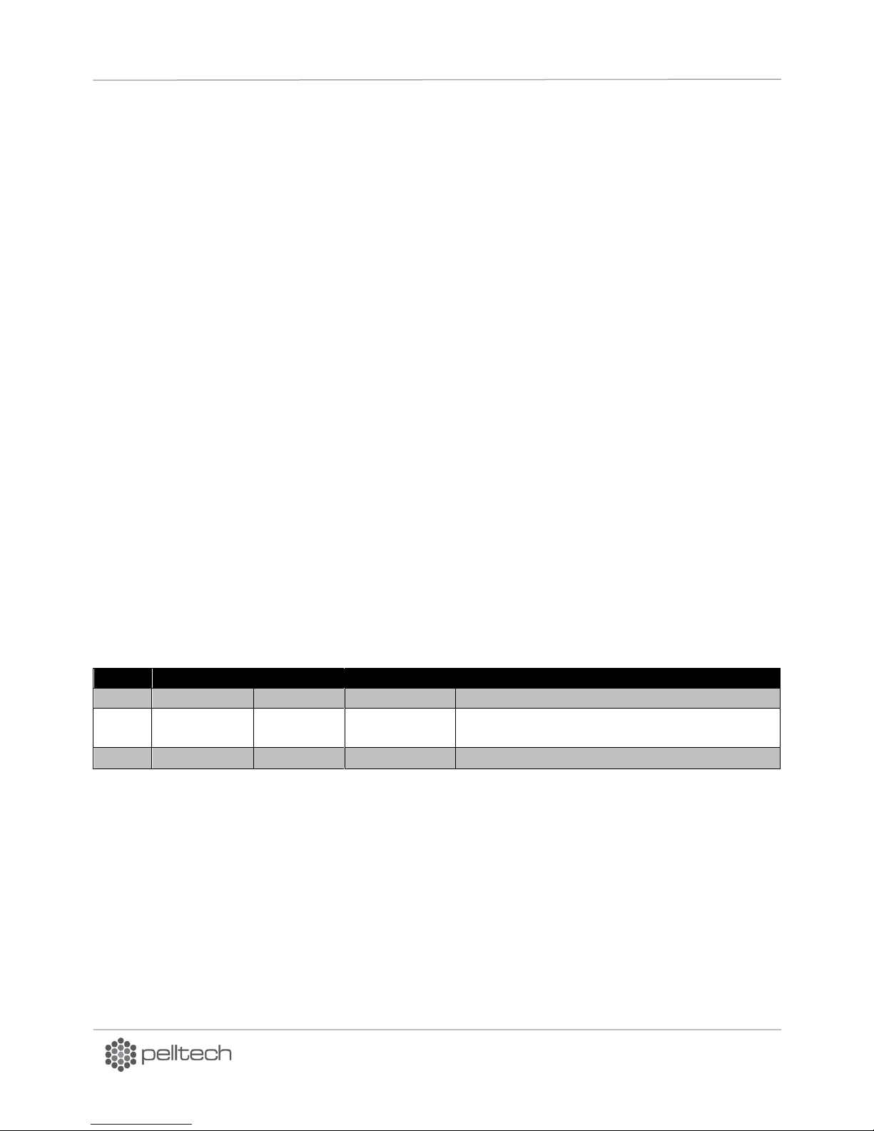
3.5 Ash removal system
The burner can control external ash removal auger and scraper motors via X25 connector. During
burner’s cleaning cycle the X25 connector is powered and ash removal and scraper motors can be
switched on via X25 connector’s L1 and L2.
3.6 External boiler temperature sensor
External temperature sensor enables the burner to maintain constant boiler’s water temperature. For
that external temperature sensor has to be installed to relevant place on boiler, existing burner’s
temperature sensor to be disconnected from TMP1 connector on controller’s board and external sensor
to be connected to connector TMP1. In parameters menu PAR53 value has to be chosen “2”.
When temperature holding status is activated, then burner will change its capacity according to water
temperature and speed of temperature changing. Burner starts to change its capacity when BURNING
status has lasted longer than set in PAR15. Capacity is changed after time set in PAR17.
Following actions must be done to enable temperature hold mode (THM):
1. Mount external temperature sensor to boiler according to boiler manufacturer instructions.
2. Connect the sensor to TMP1 connector on controller board.
3. Choose PAR53 value (sensor type) according to Table 7.
4. Set requested temperature – PAR54. It should be lower than boiler thermostat temperature.
Otherwise the boiler thermostat would force the burner to turn off before reaching PAR54 value.
5. Optionally PAR55 - the hysteresis of requested temperature can be changed.
THM activates if PAR53 value is larger than “1” and BURNING status has lasted longer than set in PAR15
typically 30min). The burner will change its output power according to current measured temperature
and the rate of temperature change. New power level is selected after every time interval specified in
PAR17.
Table 7 PAR53 values
After activating THM, following row is displayed on INFO-screen e.g.: „T=22.3/70±5↓200o“. It means
following:
22.3 – Actual measured temperature.
70 – Set point temperature (PAR54).
±5 – Set- point hysteresis (PAR55).
↓ - Shows weather actual temperature is increasing or decreasing.
200o – Forecasted temperature in 10min.
DK9401B1 www.pelltech.eu
Page 32
PV700a / PV1000a pellet burners
p 32/ 59
Button
Push time
Action
OK
<3s
To enter to setup menu
To confirm settings (in parameter edit mode)
OK
>3s
To reset error, resume normal operation
To reset counter (only in counter screen in INFO menu)
<
To move back in menu by one level
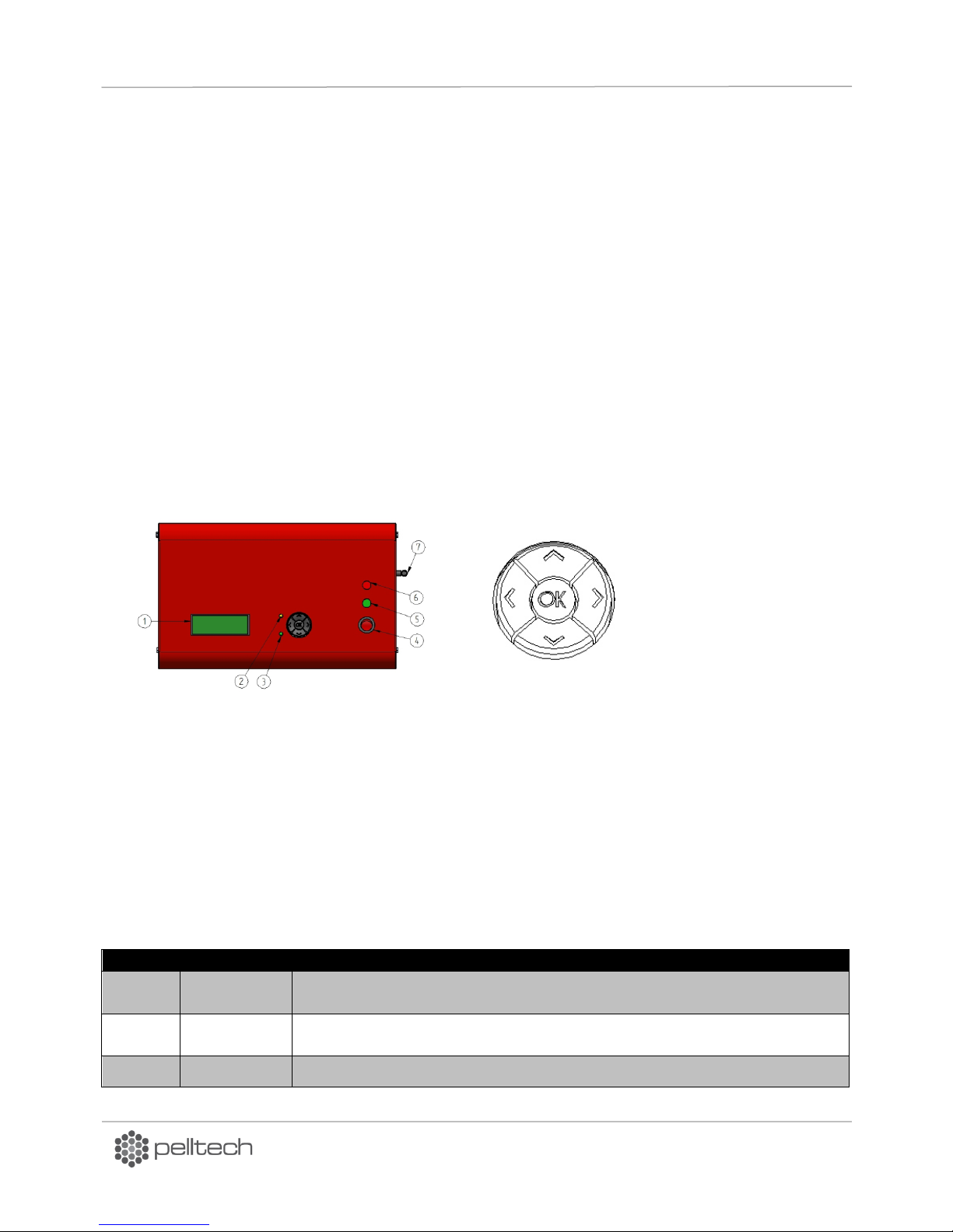
1 – 4x20 character display
2 – Yellow LED, indicates if flame is detected in burning chamber
3 – Green LED, indicates if pellets are present in internal feeder
4 – Burner on/off switch with power indication light.
5 – Burner operation light, showing if the boiler thermostat sends a signal to the burner.
6 – Fault light of safety circle
7 - GSM modem antenna
Figure 32 User interface
Table 8 User interface controls
4 Operation and service
4.1 User interface
The burner is controlled via user interface on the front panel. 3 row LCD screen (1) displays main menu,
submenus, event log and statuses. Yellow light (2) shows the existence of flame in burning chamber. If it
blinks, the burner is out of normal operation. Green light (3) indicates existence of pellets in the burner.
Burner on/off switch (4) can be used any time to turn the burner safely on or off. Operation light (5)
indicates weather the boiler thermostat is turned on or off. Fault light (6) is connected to safety circle
and indicates its being in order.
“Up” and “down” (Ʌ V) buttons enable to move in menus.
“Left” and “right” (> <) buttons enable to control the burner and change parameters. To get back to
main menu (<) button is used. It acts like an escape button. “Right” (> ) button enables to change values
in selected parameter. To enter to setup menu or to confirm changes of values OK button is used. OK
and < buttons have different functions depending on context. See Table 8.
DK9401B1 www.pelltech.eu
Page 33

PV700a / PV1000a pellet burners
p 33/ 59
To cancel change (in parameter edit mode)
OK + <
>3s
To restart burner
4.2 Starting and stopping
To turn on the burner:
Turn on boiler main switch.
If burner displays STOPPED, then go to main menu and BURNER set from ON to OFF. WAITING is
displayed.
Turn boiler’s thermostat to requested temperature.
Burner goes to TESTING state and then to LOADING state. If this is the first run, external auger needs
to fill up with pellets. It can take as long as 20minutes, because external auger has to be filled with
pellets.
To stop the burner:
set in main menu BURNER from ON to OFF. Now the burner will burn all pellets in burning chamber
and turn safely to STOPPED mode.
STATUS menu displays the changes:
BURNING SLOW DOWN END BURN END BLOW WAITING STOPPED
The stopping procedure may take up to 30 minutes.
Attention! If necessary the boiler’s thermostat can be turned on/off from burner red switch with power
indication light Figure 32.
Caution! Do not turn off mains power to terminate burning process. Use the boilers thermostat for that.
In order to complete burning procedure safely let the burner to burn all fuel in burning chamber. Never
leave burner unattended when you had to stop boilers work turning boiler off from mains switch in any
reason.
4.3 Fuel refilling
Fuel container (silo) has to be refilled before its runs out. The fuel can be added any time to container
(silo). If container runs out before refilling, refill it and restart the burner. The start-up takes now longer
about 20 minutes, because external auger has to be filled with pellets like in initial start-up. Turn burner
from BURNER menu ON. Vice versa the LEVEL ERROR will be displayed, because loading time is
exceeded.
4.4 Statuses and parameters
PV700a/PV1000a pellet burner operates in many different states, which are called “Statuses” and which
are displayed in user interface in STATUS menu (chapter 4.1). Burner changes its statuses based on input
signals from sensors and user setup. The working statuses of the burner in typical order of succession are
given in Table 9.
The duration of all actions are in form mm:ss (’m’ in the middle) or hh:mm (’h’ in the middle). For
example: ’IGNITING 01m25“means the burner ignition state lasted 1 minute and 25 second.
DK9401B1 www.pelltech.eu
Page 34
PV700a / PV1000a pellet burners
p 34/ 59
Status
Short description
WAITING
Waiting when boiler’s thermostat switches on.
TESTING
Boiler’s thermostat is switched on, testing the battery, fans, feeder, level sensors and
draught in progress.
CLEANING
Ash removing from burning chamber.
LOADING
Loading pellets with external auger into burner and by feeder auger into burning
chamber.
IGNITING
Igniter is turned on, pellets are ignited.
PRE-BURN
Flame is recognized, small amount of pellets is added by feeder auger.
HEAT UP
Burning chamber ceramic stones are heated up.
BURNING
Normal burning operation.
HOLD FLAME
Thermostat is switched off, small flame is held alive.
END BURN
Thermostat is switched off, feeder is burned up.
END BLOW
Pellet coals in burning chamber are burnt, flame has disappeared.
WAITING
Burner waits when boiler’s thermostat switches on.
Test name
PAR No
Value
Unit
Test conditions
Battery voltage
-
22 V Battery loading is turned OFF and feeder is turned ON voltage must be greater than 24V.
Feeder current
PAR 46
3..6 A Feeder auger is turned ON – feeder current must be smaller
than PAR 46.
Draught
PAR62
+10
Pa
All fans are turned on. Draft must be under PAR 62.
Primary fan
PAR4
38
rot
Fan must rotate faster than 35rot = 38 (PAR4) – 3.
Secondary fan
PAR4
38
rot
Fan must rotate faster than 35rot = 38 (PAR4) – 3.
Table 9 Summary of burner statuses
At WAITING status, the burner waits when boiler’s thermostat switches. There is no time limit for
WAITING status. Only feeder auger is working periodically at WAITING status and makes ½ rotations
after every 2 minutes. With this feeder augers spiral cleans feeder’s tube from wastes.
When boilers thermostat switches on, burner will go to TESTING.
At TESTING status, burner‘s integrity and important device functioning are checked. List of tests is given
in Table 10.
Table 10 List of tests in TESTING status
At CLEANING cycle, the linear actuator moves the grates and pushes out from burning chamber the ash
and residues. The cleaning cycle has been divided into 3 steps:
1. Grates are pulled fully in to actuator end limit.
2. Grates are pushed fully out to actuator end limit.
3. Grates are moved to middle position.
DK9401B1 www.pelltech.eu
Page 35
PV700a / PV1000a pellet burners
p 35/ 59
PAR name
PAR No
Value
Unit
Test conditions
CLEANING CYCLE
PAR48
0...250
min
BURNING time between two CLEANING cycles. If set
to 0 then CLEANING is turned off. If BURNING has
been longer than 2x PAR48 set, then extraordinary
cleaning will made.
GRATES CURRENT
PAR47
0.2..6
A
Linear motors maximum current level. If greater, then
motor is stopped and cleaning cycle is started again.
Linear motor’s
min. current
-
0.1 A If current is smaller, then motor is stopped and
running direction can be changed.
Max. move time
-
58
sec
Maximum time to move actuator to one direction.
Max. cleaning
time
-
100
sec
Maximum CLEANING cycle time.
PAR
No
Parameter name
Default
value
Unit
Comment
PAR24
LOADING FEED
35..40
rot
Number of feeder auger rotations needed to load
pellets into burning chamber. Depends from burner
model.
PAR25
LOADING 2 FEED
5
rot
Number of feeder auger rotations for second loading.
-
Max loading time
5
min
Maximum regular loading time
-
First loading time
after manual start
20
min
Maximum loading time after manual start.
-
External auger start
3
sec
Auger Start delay if no fuel in burner
-
External auger stop
3
sec
Auger Stop delay if fuel in burner
-
Feeder auger start
1
sec
Feeder Start delay if fuel in burner
-
Feeder auger stop
4
rot
Feeder rotations made without fuel level before
stopped.
Table 11 CLEANING parameters
At the LOADING cycle, external auger is turned on. When pellet level in the burner reaches to level
sensors, internal feeder is started. Feeder auger loads necessary amount of fuel needed for ignition into
burning chamber. Amount of loaded fuel is measured by counting the rotations of feeder auger.
LOADING cycle is ended when feeder auger has made exact number of rotations pre-set in PAR24.
Table 12 Loading parameters
At the LOADING time, external auger holds permanent fuel level in the feeder auger’s tube. Depending
on the level sensor signal, the external auger is turned on or off.
Feeder auger’s work depends also on fuel level sensor signal.
Maximum loading time is limited by 20 minutes after manual (initial) start up because extra time for
external auger filling is needed. In next loadings, maximum time is limited by 5 minutes.
If maximum loading time is exceeded and silo selection on burner is used, the pellet delivery will be
switched to other external auger. In single pellet container delivery system NO PELLETS error will occur.
DK9401B1 www.pelltech.eu
Page 36
PV700a / PV1000a pellet burners
p 36/ 59
PAR No
Parameter name
Default
value
Unit
Comment
PAR8
FAN @IGNITING
25
rps
Primary fan speed at ignition.
-
Max ignition time
255
sec
Maximum ignition time.
-
Time of first loading
20
min
Maximum loading time after manual start.
-
Auger start
3
sec
Auger Start delay if no fuel in burner.
-
Auger stop
3
sec
Auger Stop delay if fuel in burner.
-
Feeder start
1
sec
Feeder Start delay if fuel in burner.
-
Feeder stop
4
rot
Feeder rotations made without fuel level before
stopped.
PAR No
Parameter name
Default
value
Unit
Comment
PAR8
FAN@IGNITING
20
rps
Primary fan speed at IGNITING and PRE-BURN
PAR39
FAN 2 MIN
7
rps
Secondary fan’s minimum speed. Used at
IGNITING, PRE-BURN, HEAT UP, HOLD FLAME
and END BLOW statuses.
PAR41
PRE-BURN TIME
25
s
Length of one PRE-BURN cycle.
PAR42
PRE-BURN CYCLES
6
x
Number of PRE-BURN cycles.
-
Pre-burn feed
1/2
rot
Number of feeder auger’s rotations at each
PRE-BURN cycle.
At IGNITING cycle the igniter is heated up and fan blows hot air on pellets in burning chamber. Hot air
ignites pellets. Igniter is working periodically at ignition time in order to avoid its overheating.
Igniter is pre-heated already in the end of loading cycle. When internal auger has made 10 rotations (full
number of load rotations is 12) the igniter is turned on for pre-heating. If the igniter has been turned on
more than 1 minute at LOADING time, then it will be turned off.
Table 13 IGNITING parameters and timing
The purpose of PRE-BURN status is to create stabile flame and assure effective pellets burning procedure
after ignition. Minimum fuel amount is added periodically at pre-burn time. Fans are working with same
speed as at IGNITION. Feeder auger makes ½ rotations at every 25 sec up to 6 rotations achieved. See
Table 14.
Table 14 PRE-BURN parameters
HEAT UP cycle is needed to slow down too fast heating up of the burning chamber’s ceramic stones in
order to minimize their thermal stress and thus prolong their lifetime.
DK9401B1 www.pelltech.eu
Page 37
PV700a / PV1000a pellet burners
p 37/ 59
PAR No
Parameter name
Default
value
Unit
Comment
PAR70
HEAT UP TIME
20
min
Initial heat up time of ceramic stones.
PAR71
HEAT UP POWER
30...70
kW
Initial heat up power of ceramic stones.
PAR72
HEAT UP
TEMPERATURE
500
°C
Ceramic stone minimum temperature.
Power
level
Level type
PV700
PV1000
Primary fan
Secondary fan
1
main
200
250
PAR 1
PAR 31
2
virtual
250
320 - -
3
main
300
400
PAR 2
PAR 32
4
virtual
350
470 - -
5
main
400
550
PAR 3
PAR 33
6
virtual
450
620 - -
7
main
500
700
PAR 4
PAR 34
8
virtual
550
770 - -
9
main
600
850
PAR 5
PAR 35
10
virtual
650
920 - -
11
main
700
1000
PAR 6
PAR 36
Table 15 HEAT-UP parameters
When HEAT UP is in mode ON - burner stops HEAT UP cycle after heat up time set in PAR70 is exceeded.
(Temperature of stones is not measured directly).
When HEAT UP is in AUTO mode - burner stops HEAT UP cycle after time set in PAR70 is exceeded or
stone temperature is higher than set in PAR72. (Temperature of stones is not measured directly).
BURNING is main action status in burner’s every day’s operation.
Burner can operate on 11 different fixed power levels. There are 6 main power levels, which can be
selected and adjusted. 5 virtual power levels (between main power levels) are for smoother operation –
they can't be adjusted or selected.
For every power level, the primary fan speed is fixed in PAR1...PAR6 and secondary fan speed in
PAR31...PAR36. The fan speed for virtual levels is calculated as average from previous and next main
level speed. Power levels are represented in Table 16.
Table 16 Power levels
DK9401B1 www.pelltech.eu
Page 38
PV700a / PV1000a pellet burners
p 38/ 59
Power
level
Burning time
min
Par 17
3
2
1
4
5
6
7
2 2 2
Selected power
Power level
Time(min)
Par 17
Par 15
Max power (par 14)
Par 15
3
2
1
4
5
6
7
2 2 2 30 30
Operation power
8
9
“End burn“
„End Blow“
„Waiting“
„Burning“
“Testing“
„Loading“
„Igniting“
„Pre-burn“
Thermostat ON
OFF
„Burning“
New operation power
Par 15
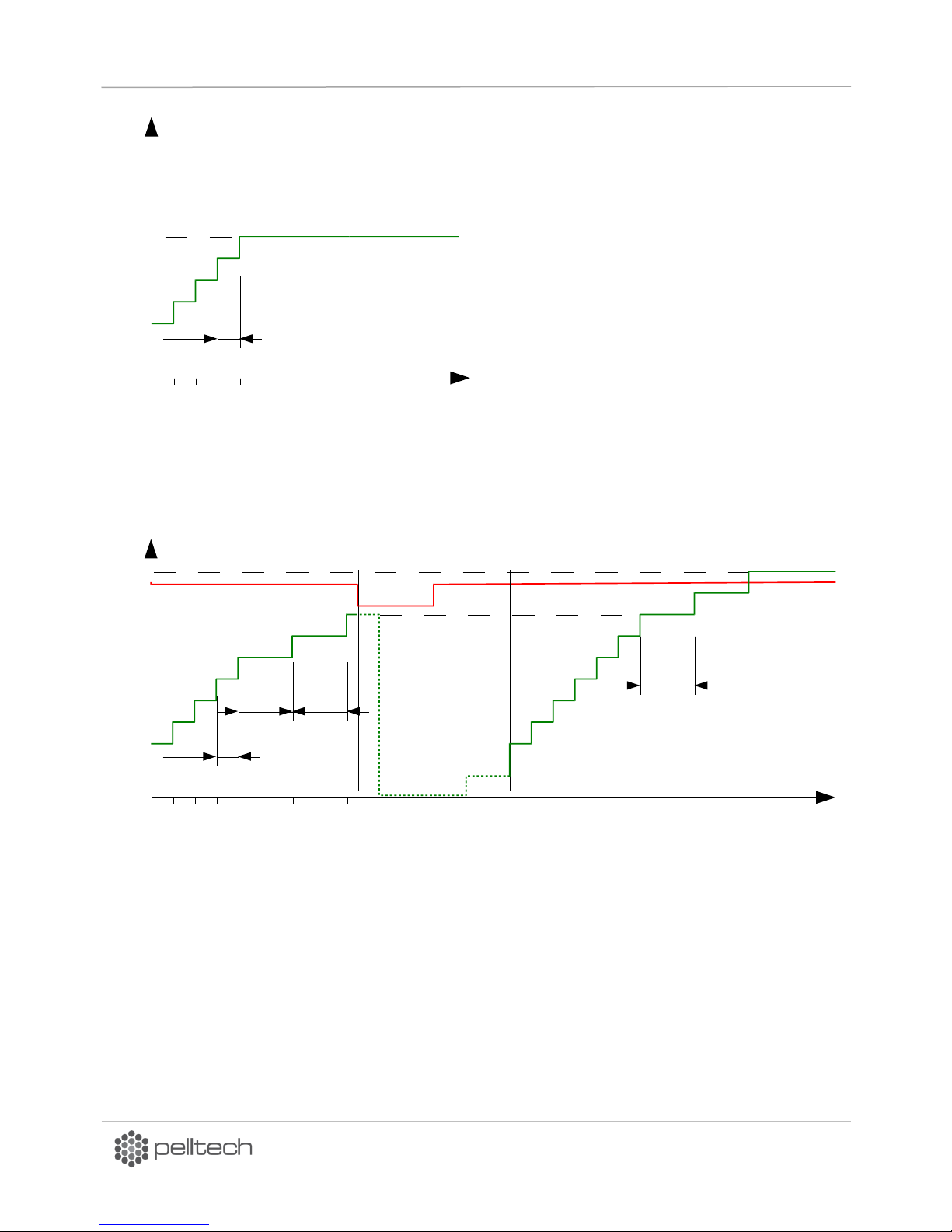
Figure 33 BURNING at fixed power
Power level can be selected in main
menu. Power level selection for
burning time can be automatic or
fixed on some main level. When
power level is fixed, the power is
slowly raised to selected level and will
be there until boiler thermostat
switches off.
In Automatic Power mode (POWER set to AUTO in main menu), the operation power is selected
automatically depending of burning cycle length.
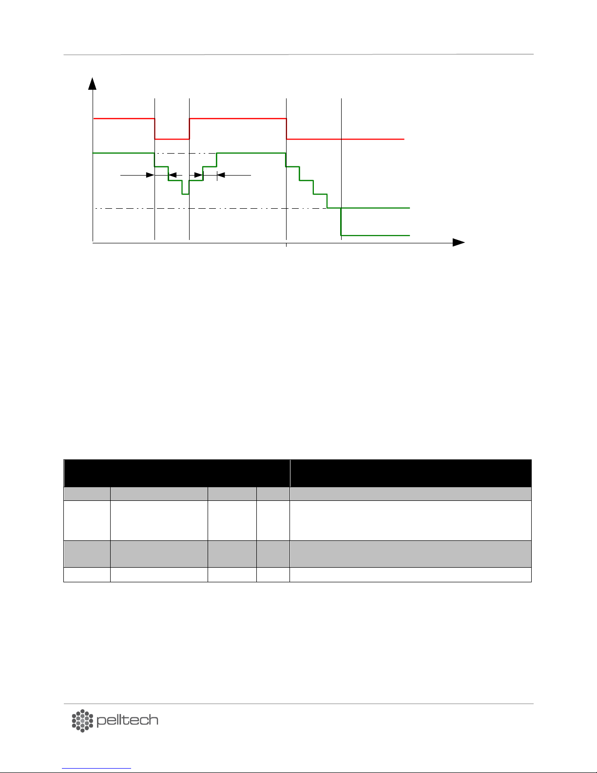
Figure 34 Burning procedure when power selection = AUTO
In SLOW DOWN mode, the burner power is reduced step-by-step to 1 level after boiler thermostat is
switched OFF. This mode can be used only in systems with high and stable power demand. Using “Slow
down” mode in systems with low thermal inertia or unstable power demand, there will be risk of system
overheating. The SLOW DOWN mode is recommended to use together with HOLD FLAME.
DK9401B1 www.pelltech.eu
Page 39
PV700a / PV1000a pellet burners
p 39/ 59
PAR No
Parameter name
Default
value
Unit
Comment
PAR10
FAN@HOLD FLAME
10
rps
Primary fan speed at HOLD FLAME
PAR39
FAN 2 MIN
7
rps
Minimum speed of secondary fan. Used at IGNITION,
PREBURN, HEAT UP, HOLD FLAME and END BLOW
statuses.
PAR11
HOLD FLAME ON
15
min
If two consecutive WAITING states have been
shorter than 15 min, HOLD FLAME will be activated.
PAR12
HOLD FLAME OFF
60
min
Maximum time when burner holds flame.
Power
level
Status/time
Par 18
3
2
1
4
5
6
7
Operation power
Thermostat OFF
„Burning“
„Slow down“
„Burn end“
„Hold flame“
Thermostat ON
„Slow
down“
„Burning“
Par 17
OR
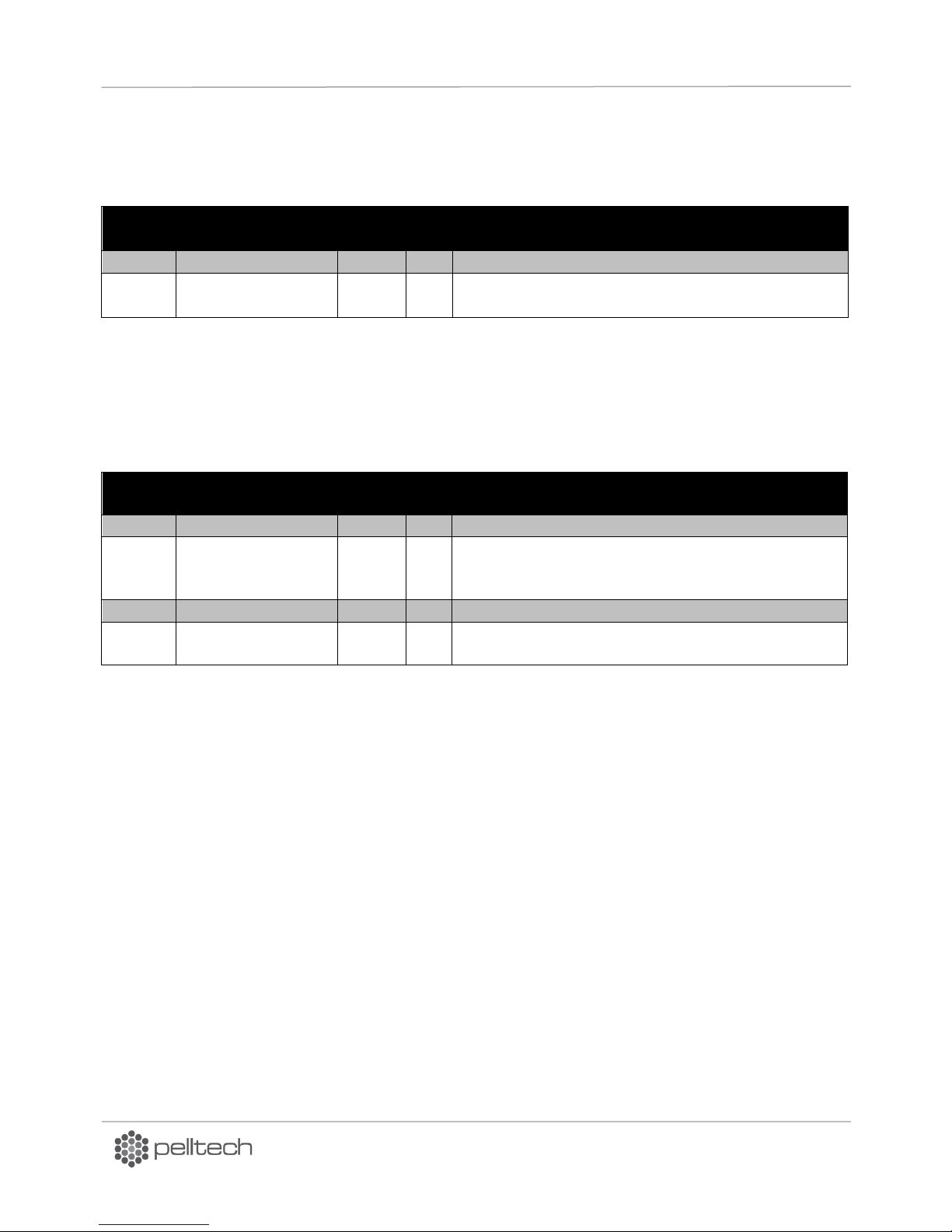
Figure 35 SLOW DOWN mode
The purpose of HOLD FLAME mode is to avoid burner start-up procedures i.e TESTING, CLEANING,
LOADING, IGNITING etc. every time, when burner is switched on from boiler thermostat. In HOLD FLAME
mode, minimum fuel and air amount are delivered to burning chamber. HOLD FLAME mode can be
switched on from burner main menu. When HOLD FLAME is set to AUTO, burner will turn the mode ON
or OFF depending on WAITING time:
If WAITING (time between END BLOW and boiler thermostat switched on) is shorter than set in
PAR 11, then HOLD FLAME mode will be switched on.
If HOLD FLAME time is longer than set in PAR12, HOLD FLAME mode is switched off.
HOLD FLAME is also used as intermediate state before CLEANING or after SLOW DOWN.
Table 17 HOLD FLAME parameters
The END BURN cycle helps securely to stop burning procedure in burning chamber of burner. All pellets
inside the burning chamber and feeder tubes will be burnt. Amounts of pellets delivered and fan rotation
speed (power level) are same as in BURNING status. If burner goes to END BURN from other states (e. g.
HOLD FLAME), the first power level is selected. Burner works in END BURN until feeder tube is empty feeder has made as many rotations as selected in PAR26. END BURN can be used in case of some
DK9401B1 www.pelltech.eu
Page 40
PV700a / PV1000a pellet burners
p 40/ 59
PAR No
Parameter name
Default
value
Unit
Comment
PAR26
END BURN FEED
50..80
rot
Feeder auger rotations to clean up feeder’s pipe.
-
Minimum feed
20
rot
If less rotation are made and boiler thermostat is
switched on then burner goes back to BURNING state.
PAR No
Parameter name
Default
value
Unit
Comment
PAR9
FAN@END BURN
20
rps
Fan speed at END BURN.
PAR39
FAN 2 MIN
7
rps
Minimum speed of secondary fan. Used at IGNITION,
PREBURN, HEAT UP, HOLD FLAME and END BLOW
statuses.
PAR27
END BLOW TIME
2
min
Time to blow air after flame is disappeared
-
Max. END BLOW
time
15
min
Maximum time when flame must disappear at END
BLOW.
occurred errors e.g. If pellets have run out and NO PELLETS is displayed the burner stops safely normal
BURNING cycle.
Table 18 End burn parameters
The END BLOW cycle is needed to burn finally all unburned pellet coals in the burning chamber. Burner
will wait for flame disappearing in burning chamber. In PAR27 is fixed the end blow time, i.e. the time
how long the fans continue to blow after flame’s disappearing.
Table 19 END BLOW parameters
4.5 Output power levels
Burner has 6 pre-set output power levels. For every level, the program calculates correct fuel amount
what depends on fuel’s calorific value and burner’s internal feeder productivity. The feeder productivity
for normal, light and heavy pellets can be changed from main menu. For normal pellets it is 160 grams
per rotation (PAR21). Calculated amount of fuel is divided into periodic feeding cycles. In every normal
cycle internal feeder makes half rotation. If the calculated time of cycle comes too short then the cycle
length will doubled and fuel will loaded with full rotation of feeder. For every power level there is
different pre-set fan rotation speed (PAR1..PAR6).
Burner chooses the output level between pre-set min and max powers. When burning time has been
more than 15 minutes (PAR15), next time burner takes one power level up, when burning time has been
less than 30 minutes (PAR16), next time burner takes one power level down.
4.6 Main menu and settings
To enter to set up menu press OK. To go back to main menu, press < button.
DK9401B1 www.pelltech.eu
Page 41
PV700a / PV1000a pellet burners
p 41/ 59
Menu
nr
Menu para-
meter ENG
Description
Default
settings
Options
1
STATUS->
Submenu with status
2
INFO->
Burner’s info
3
BURNER
Burner’s turning
OFF
ON/OFF
4
HOLD FLAME
Hold flame allowed
OFF
ON/OFF/AUTO
5
HEAT UP
Slow heat up
AUTO
AUTO/ON/OFF
6
SLOW DOWN
Slow cool down
OFF
ON/OFF
5
PELLETS
Fuel quality options
NORM
NORM/LIGHT/HEAVY
7
POWER
Power level selection
AUTO
PV700:
AUTO/200/300/400/500/600/700
PV1000:
AUTO/250/400/550/700/850/1000
8
BASE AIR
Fan speed change at
once for all power levels
0
-2/-1/0/+1/+2/+3/+4/+5
9
SILO
Container selection
1
1 2 3 4
10
LANGUAGE
Language options
ENG
Annex 5 List of languages
11
PARAMETERS -
Parameters menu
Annex 4 List of parameters
Screen text
Description
Pwr 150/700 kW
actual and selected power. Max power can be changed from main menu.
Tstn=1810C T1=205,70C
Tstn – fire brick temperature and boiler’s temperature.
Fan=27/28±2 12/13
27 – Primary fan’s actual speed.
28 – Primary fan’s set-point speed. Actual speed is controlled to match
set-point speed.
±2 - Base air value. Controller tries to keep speed set-point + base air. In
this case controller keeps speed 15rps. Speed unit is rps (rotations per
second).
12/13 – same as above for secondary fan. Base air setting is same ±2.
Table 20 Main menu
STATUS info screen displays last events (burner states) and their duration. The duration is in form mm:ss
(’m’ in the middle) or hh:mm (’h’ in the middle). For example “Igniting 01m25 means the burner ignition
state lasted 1minute and 25 seconds. Last row of the log shows current state. To reach the last row,
press the “down” button, until you reach the current state. The duration of current state updates every
second or minute.
INFO menu is useful to troubleshoot various problems. It gives access to some input signals and internal
parameters. Use up and down arrows to scroll through info menu.
Note: Comma “,” is used as decimal separator.
Table 21 Info menu description
DK9401B1 www.pelltech.eu
Page 42
PV700a / PV1000a pellet burners
p 42/ 59
Δp=-0,2/-8Pa
Measured under pressure value in bpoler. -0,2 is actual pressure and -8 is
set-point. Controller regulates flue gas fan speed to keep this pressure.
Depends also on PAR60 value.
Total=10 kg
Roughly the amount of pellets burnt. It is measured by counting internal
feeder rotations. Number is reset by firmware upgrade
Count=12,1 kg 180/254
Roughly the amount of pellets burnt, resettable by user.
U=25V68 I=0.0A
U - DC power voltage 25V68 means 25.68V. I – Feeder’s or grate’s motor
current.
Ver=2.08 19/12/12
Firmware version and date.
Menu BURNER enables to turn burner safely ON or OFF.
The main idea of HOLD FLAME function is to reduce permanent ON OFF cycles. This function is useful if
burner’s working time is much longer than WAITING time. For example 1 hour of working time and 10
minutes of waiting time. In „HOLD FLAME“status the fan rotates slowly (PAR10) and small quantities of
fuel are added to burner. Existence of flame is not checked. Such status may last max one hour, after
what burner ends usual BURNING cycle and goes to WAITING. If boiler’s thermostat switches on before
an hour, burner goes to BURNING state. HOLD FLAME is activated when it is set to AUTO and two
WAITING times have been shorter than set value in PAR11. HOLD FLAME turns off if flame has been hold
more than PAR12 value.
HEAT UP status enables slow heat up of fire bricks. It reduces termal stress and prolongs their lifetime.
SLOW DOWN enables slow cooling down of fire bricks. It reduces termal stress and prolongs their
lifetime.
Menu PELLETS enables to select between 3 pre-set fuel quality options. Depending on fuel quality the
mass of fuel could differ in same amount. That’s why the calorific value of same amount may differ. By
default burner calculates that one rotation pushes 80 grams pellets (PAR21) to burning chamber. If
pellets density is smaller i.e. they are lighter, then with one rotation less pellets will be delivered into
burning chamber. Such mistake has to be compensated by choosing LIGHT from PELLETS menu. Now
burner calculates that one rotation equals with 75 grams of pellets (PAR31) and makes more rotations. In
general case there is no need to make change in PELLETS menu.
Menu POWER determines caloric productivity of burner in kilowatts. Power is calculated by reading the
rotations of the feeder auger, taking into account average caloric value of 1 kg of pellets. It is possible to
pre-set particular (200; 300; or else) power level value or AUTO - automatically selected value. In AUTO
status burner selects necessary power level depending on time what is needed to achieve pre-set
temperature. Burner changes its capacity what is determined by parameters MIN POWER (PAR13) and
MAX POWER (PAR14). If burner cannot achieve pre-set temperature in certain time (PAR15) it will raise
its power automatically by one level and continues rising power up to reaching maximum level (PAR14)
or boiler has achieved pre-set temperature.
If boiler achieves pre-set temperature faster than set in PAR16 burner will work one power level lower in
next cycle. Power will be reduced as long as burner has reached minimal power level (PAR13).
DK9401B1 www.pelltech.eu
Page 43

PV700a / PV1000a pellet burners
p 43/ 59
Message on
screen
Reason and solution
BATTERY LOW
Battery voltage is less than 24V with load (working feeder motor).
o When there was blackout then just wait when battery recharges itself.
o Replace battery.
IGN.ERROR
No flame detected at ignition time.
o Igniter is out of order or fuse is blown. Usually fuse blows when igniter is broken or its body
is in short circuit. Replace fuse or igniter
o Flame sensor is dirty or smelt. Clean or replace sensor if needed.
Menu BASE AIR increases or decreases speed of fan in all power levels by same number. It is
reasonable to use base air to balance different characters of particular heating systems. For example if
draught is very strong, the fan can work at lower speed and thus reduce the draught.
SILO menu enables to burner to choose between four pellet containers.
Menu LANGUAGE enables user to select between 17 languages. Table of languages is in Annex 5.
Menu PARAMETER gives overview of burner’s default and minimum- maximum settings. The menu
enables fine tuning of the burner what in general is not necessary. Short description of burner’s parameters
is given in Annex 4.
4.7 Regular maintenance
Pellet burner requires systematic maintenance. The maintenance period depends on the quality of the
pellets and heating intensity. The boiler must be cleaned weekly. For more information about cleaning
the boiler, please see boiler's user manual.
The burner should be cleaned at least two times in a heating season.To clean the burner:
1. Turn off the burner by turning the boiler’s thermostat to 0.
2. Let the burner cool down for at least 1 hour.
3. Open the boiler's door to gain access to the burning chamber.
4. Remove the grates and clean them from any residues. Before removing is recommendable to
mark grates. Make sure that all holes on the grates are clean.
5. Remove the bottom panel to gain access under the grate movers to clean the ash from the
burning camber.
6. Reattach the bottom panel.
7. Place back the grates taking into account their marking. Ensure that grates fit to holders.
8. Close the boiler's door to finish the maintenance and turn the thermostat to desired
temperature.
The connection between the boiler and chimney must be completely airtight. There mustn't be any
extra draught in the smoke draft of the boiler. All cleaning and maintenance openings must be closed
with covers.
5 Problems and solutions
DK9401B1 www.pelltech.eu
Page 44

PV700a / PV1000a pellet burners
p 44/ 59
o Amount of pellets for igniting is too small. If error is frequent, increase amount of pellets
PAR24.
STOPPED
Burner is turned OFF from main menu.
o To turn burner on hold OK button down 3 seconds or change in BURNER menu OFF to ON.
LEVEL ERROR
Feeder auger doesn’t rotate.
o Remove plastic hose and check is there any foreign object or very long pellet jammed the
feeder auger. Remove obstacle.
Level sensor is dirty or smelt. Clean or replace sensor if needed.
Poor draught, dirty sensor. Check sensor, clean if needed. Improve draught.
NO PELLETS
Max loading time is reached, but level sensor hasn’t detected enough fuel in feeder or in
burning state during 4 minutes no pellets detected.
o No pellets in container. Check existence of pellets, refill container.
o External auger is broken. Check fuse and connection with burner. Replace fuse or auger.
o Fuel level sensor is broken or short. In this case transparent tube has to be filled with
pellets. Replace sensor.
o Too much sawdust in container and external auger can’t reach the pellets. Remove
sawdust.
NO FLAME
Flame is disappeared at pre-burning time or at burning time.
o Fuel level sensor is dirty or broken. Check sensor, clean or replace if needed.
o Flame sensor is dirty or smelt. Clean or replace sensor.
SRP
Appears in screen for some seconds when turning on the burner.
o If message doesn't disappear push any button on the front panel.
FEEDER
ERROR
Feeder auger has not made any rotations in 8 seconds at its running time.
o Feeder auger motor’s rotation sensor is too far from magnet. Check sensor’s placement.
It has to be located maximally on magnet and not far than 2..3 mm. Sensor has not to touch
rotating parts of motor.
o Feeder motor’s reducer may be broken (if motor makes noise). Replace both.
Feeder auger motor current has reached its limit and over-current protection applied.
o Feeder auger may be blocked or jammed by foreign object. Remove obstacle.
FAN ERROR
Fan has not reached enough speed at testing time.
Fan motor’s rotation sensor is too far from magnet. Check sensor’s placement. It has to be
located maximally on magnet and not far than 2..3 mm. Sensor has not to touch rotating
parts of motor.
o Fan doesn’t rotate. Bearings too dusty or fuse blown. Clean bearings or replace fan.
o Fuse has blown. Replace fuse.
NO POWER
The mains supply doesn’t reach controller.
o Back burning and safety thermostat have turned mains off. Possible reasons are poor
draught, too much ash in burner or in boiler or poor burning procedure. Improve draught,
remove ash, use only quality pellets. Poor burning may be caused by big amount pellets
feed (heavy pellets) or poor stream of the air. Change PAR23 “heavier”.
o General blackout. Wait for end. Restart burner.
OVERHEAT
Burner internal temperature reached over set-point as fixed in setup menu.
Possibly back-burning is happened.
o Bad connection of temperature sensor. Check and improve if needed.
o Insufficient entrance of fresh air into the boiler room. Draught to wrong direction. Ensure
DK9401B1 www.pelltech.eu
Page 45
PV700a / PV1000a pellet burners
p 45/ 59
availability of fresh air and improve draught.
GRATE ERROR
Over- current of grate movers motor has exceeded value set in PAR47 and over- current
protection has applied.
o Ash removing grate has jammed before reaching extreme point. Remove reason.
Motors power screw got dirty and stops rotation. Clean the screw.
Screen empty,
backlights on
Controller error or screen error.
o Replace respective component.
The contrast of screen is poor. Contrast can be adjusted with small screwdriver by turning
the resistor CONTR on down edge of controller. In one extreme the screen displays nothing
and in other extreme screen is filled with black rectangles.
Screen empty
no backlights
No mains supply.
Status
Next Status
Change conditions
WAITING
TESTING
Boiler’s thermostat switches on.
TESTING
CLEANING
All tests are passed successfully
BATTERY
ERROR
Battery voltage is less than 24V in burdened status.
FAN ERROR
Fan does not reach 40 rps at PRE-BURN.
LEVEL ERROR
The level sensor recognizes pellets in the feeder.
CLEANING
LOADING
The grates are moved and ash is removed from burning chamber.
GRATE ERROR
Grates are not moving as expected.
LOADING
IGNITING
Feeder makes loading rotations 40 rot/min (PAR24).
NO PELLETS
Maximum loading time (5 min normal or 20 min initial) is reached.
END BURN
Flame detected and unknown start conditions. LOADING restarts.
LOADING 2
IGNITING
Previous state was ignition and feeder made 3 rotations.
PRE-BURN
Previous state was hold flame and feeder made 3 rotations.
IGNITING
PRE-BURN
Flame recognized.
LOADING 2
Max ignition time (255* sec) is reached and load 2 is not done.
IGN. ERROR
Max ignition time 255 sec is reached and load 2 is done.
6 Burner status change logic
Table 22 Error messages in screen
DK9401B1 www.pelltech.eu
Page 46
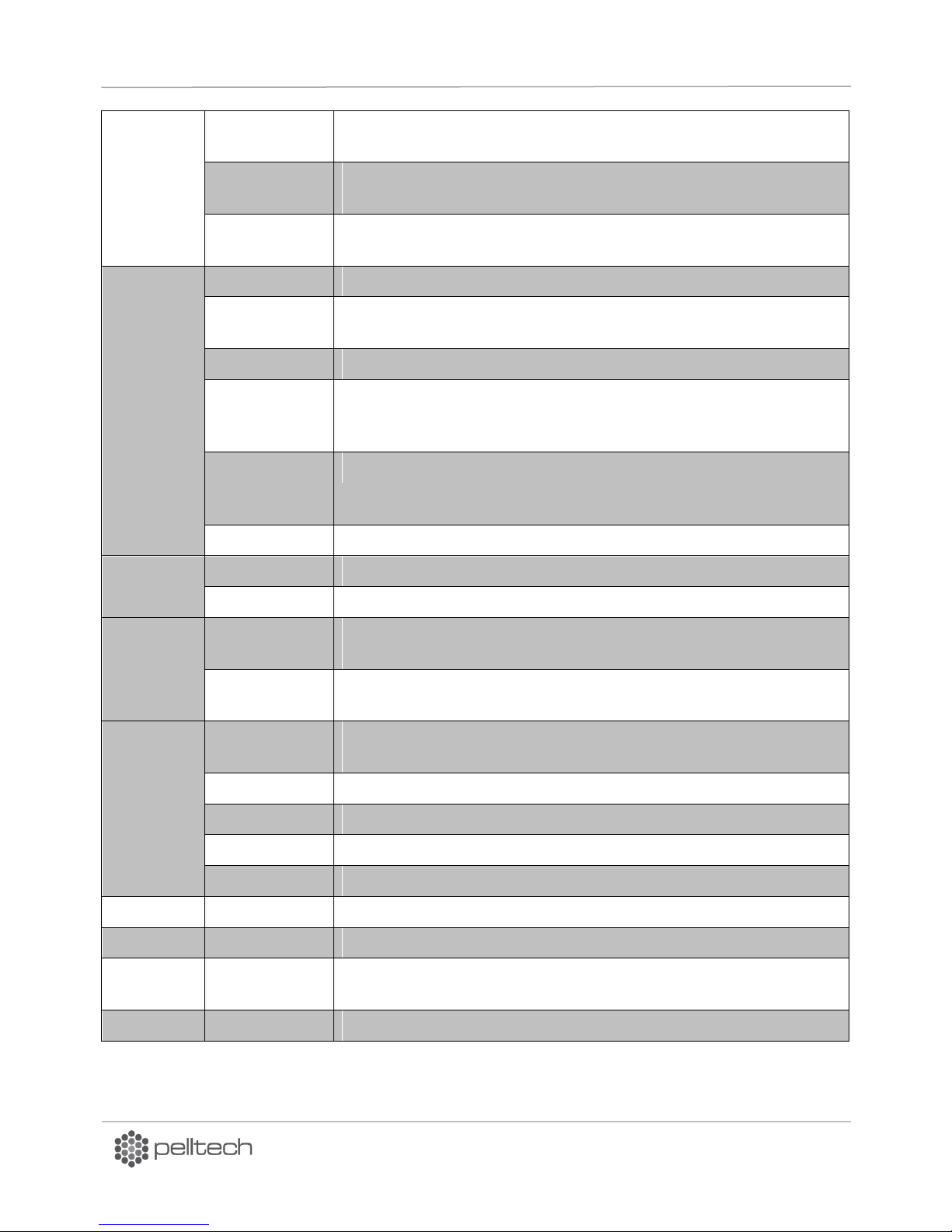
PV700a / PV1000a pellet burners
p 46/ 59
PRE-BURN
BURNING
3 pre-burn cycles each 40 sec are done and continuous flame is
recognized more than 10 seconds.
LOADING 2
Pre-burn cycles are done and flame is NOT recognized and load 2 is
NOT done.
NO FLAME
Pre-burn cycles are done and flame is NOT recognized and load 2 is
done.
BURNING
END BURN
Boiler’s thermostat is NOT switched on. (HOLD FLAME is NOT allowed).
HOLD FLAME
Boiler’s thermostat is NOT switched on. (HOLD FLAME is in AUTO
mode).
END BURN
Maximum continuous burning time (4 hours) is reached.
BURN END ->
END BLOW >LEVEL ERROR
Fuel level is continuously detected in time of 8 feeder auger rotations.
BURN END ->
END BLOW >NO PELLETS
Fuel level is not detected in 4 min.
NO FLAME
No Flame more than 2 minutes
HOLD
FLAME
LOADING 2
Boiler thermostat is switched on.
END BURN
Max KEEP FLAME time (1 hour) is reached
END BURN
END BLOW
Flame is not recognised in 1 min and boiler’s thermostat is switched
off.
BURNING
Boiler thermostat is switched on, feeder auger has made less than 8
rotations and previous state was BURNING.
END BLOW
WAITING
Burning end. Feeder auger has made 15 + 10 rot and blowing time 60
sec is reached.
STOPPED
Flame is not recognised in 1 min and burner is not switched on.
NO FLAME
In Burning status flame misses more than 1 minute.
LEVEL ERROR
In Burning status level of fuel in feeder’s inlet doesn’t decrease.
NO PELLETS
No pellets recognised in feeder’s inlet.
NO POWER
WAITING
Power exists and boiler’s thermostat is switched off.
STOPPED
Power exists and boiler’s thermostat is not switched on.
BURNING
If status before No Power was Burning and No Power didn’t last more
than 5 min.
Any other
WAITING
Boiler’s thermostat is switched on.
DK9401B1 www.pelltech.eu
Page 47
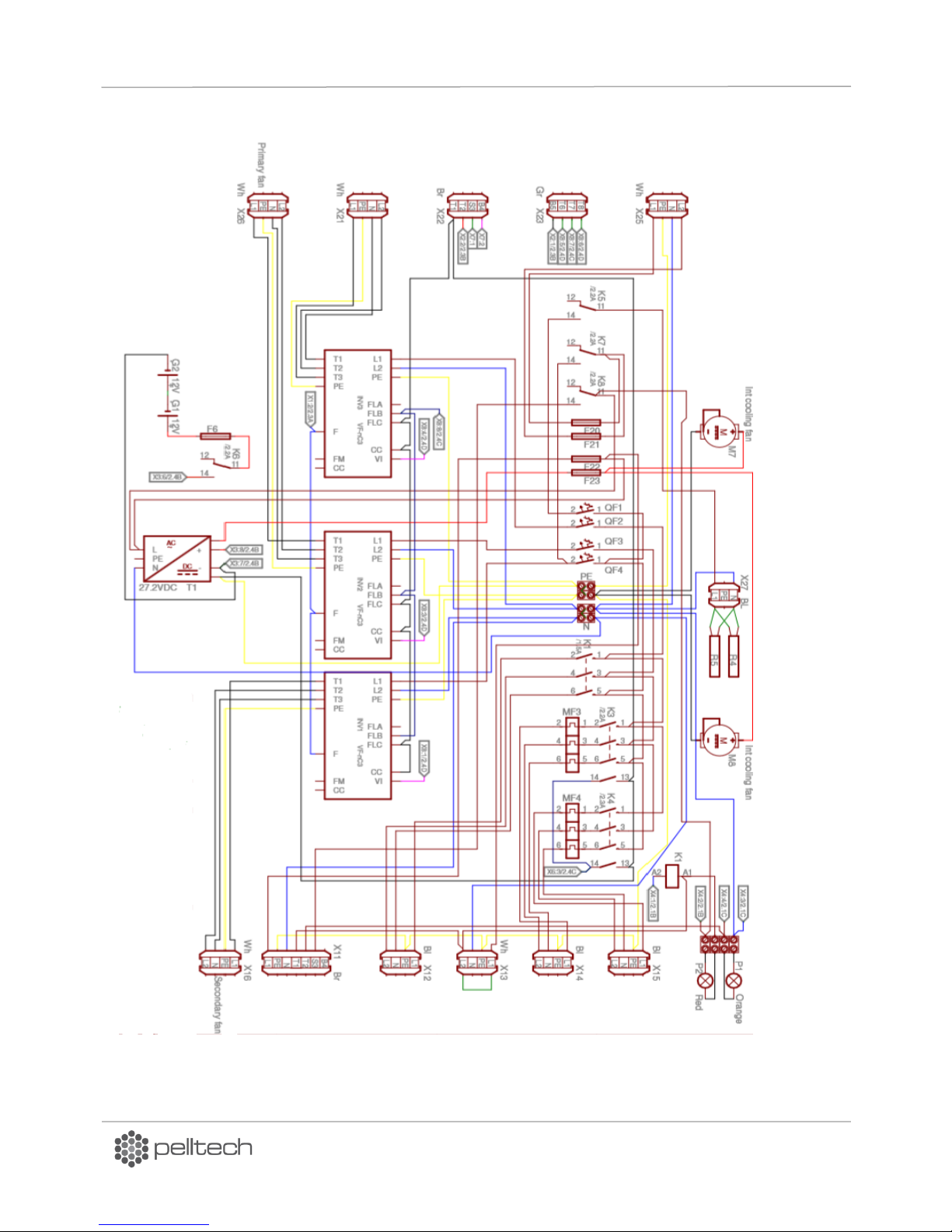
PV700a / PV1000a pellet burners
p 47/ 59
Bl Black
Br Brown
Bu Blue
Gr Green
Rd Red
Wh White
YL Yellow
Figure 36 PV700 Electrical diagramm
7 Annex 1 Electrical diagrams
DK9401B1 www.pelltech.eu
Page 48
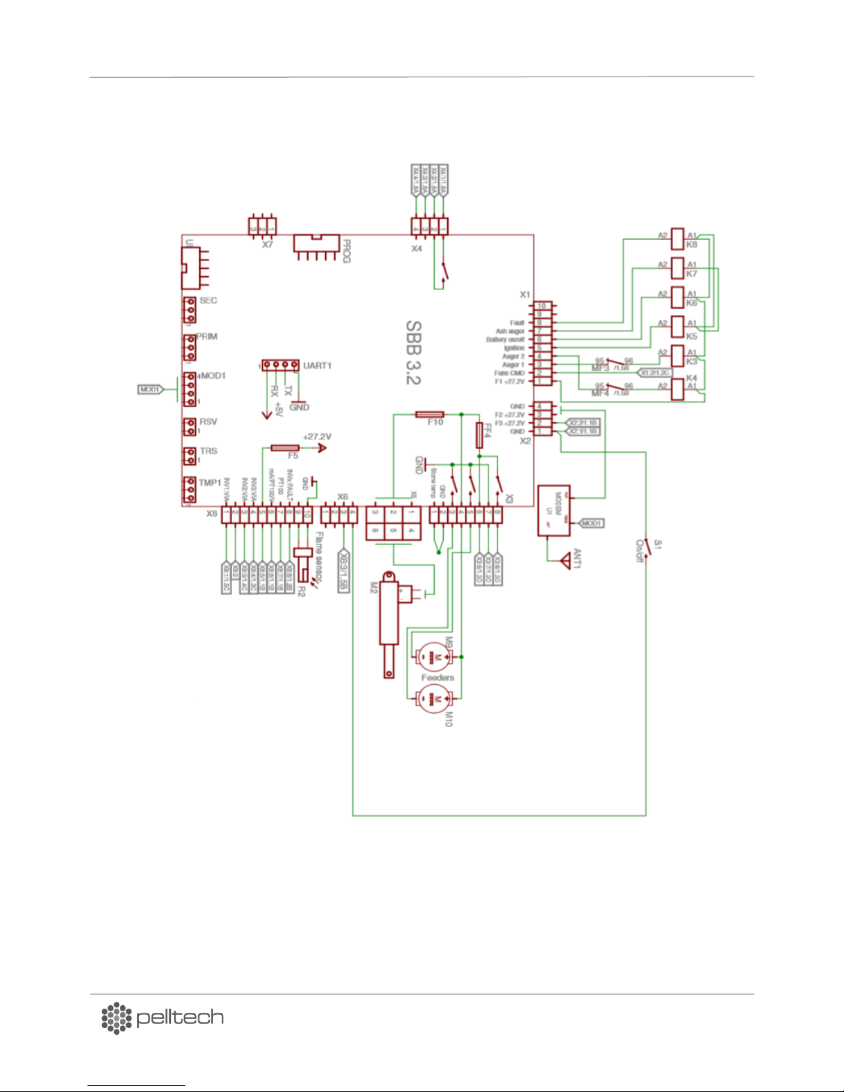
PV700a / PV1000a pellet burners
p 48/ 59
Bl Black
Br Brown
Bu Blue
Gr Green
Rd Red
Wh White
YL Yellow
Figure 37 Principle diagram
DK9401B1 www.pelltech.eu
Page 49
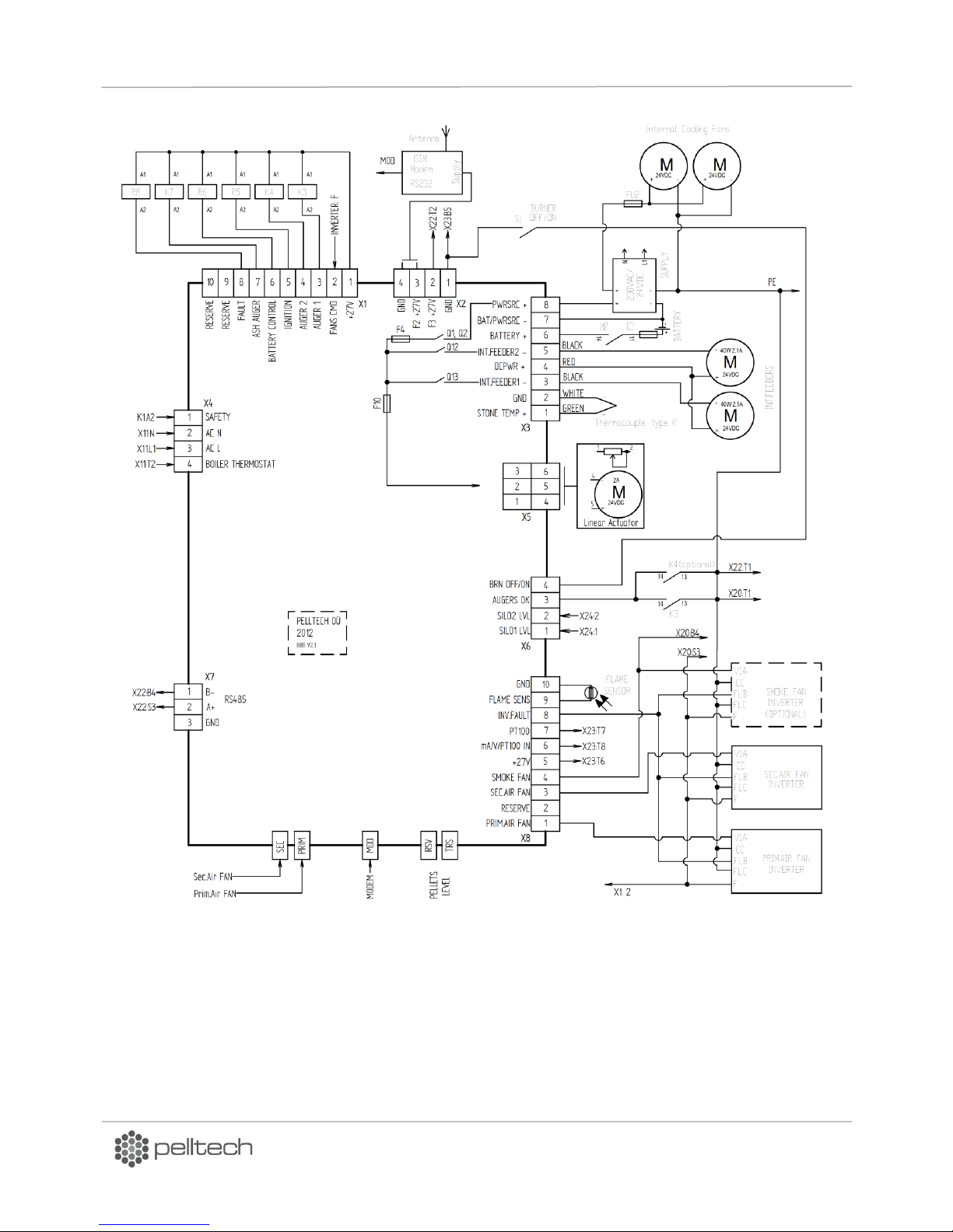
PV700a / PV1000a pellet burners
p 49/ 59
Figure 38 Principle diagram
DK9401B1 www.pelltech.eu
Page 50
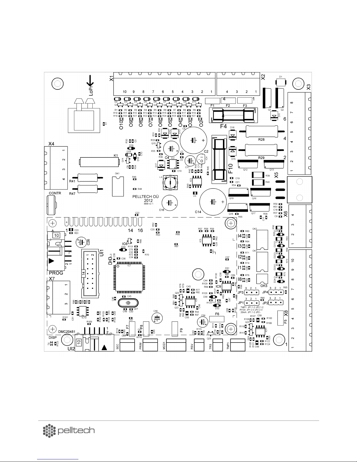
PV1000a pellet burner
p 49/ 58
Fuse F4=6A 24VDC Power supply
Fuse F10= 2A Linear motor
Figure 41 Controller board BBB v2.1
8 Annex 2 – Controller board
DK9401B1 www.pelltech.eu
Page 51

PV1000a pellet burner
p 50/ 58
Connector
Description
LoPr
Boiler pressure sensor connection. Must be connected to tube on left
feeder tube.
FANx-1
Prim/sec fan speed sensor +5V power
FANx-2
Prim/sec fan speed sensor GND
FANx-3
Prim/sec fan speed sensor digital input
MOD1-1
Modem interface +5V output, fused through F9
MOD1-2
Modem interface Rx input
MOD1-3
Modem interface Tx output
MOD1-4
Modem interface GND
TMP1-1
Temperature sensor power +5V
TMP1-2
Temperature sensor GND
TMP1-3
Temperature sensor signal 0 – 2.5VDC
RSV-1
Level sensor receiver diode cathode
RSV-2
Level sensor receiver diode anode
TRS-1
Level sensor transmitter LED anode
TRS-2
Level sensor transmitter LED cathode
X1-1
+27VDC power output, fused through F1
X1-2
Open collector output, max 200mA, 30VDC
X1-3
Open collector output, max 200mA, 30VDC
X1-4
Open collector output, max 200mA, 30VDC
X1-5
Open collector output, max 200mA, 30VDC
X1-6
Open collector output, max 200mA, 30VDC
X1-7
Open collector output, max 200mA, 30VDC
X1-8
Open collector output, max 200mA, 30VDC
X1-9
Open collector output, max 200mA, 30VDC
X1-10
Open collector output, max 200mA, 30VDC
X2-1
GND
X2-2
+27VDC power output, fused through F3
X2-3
+27VDC power output, fused through F2
X2-4
GND
X3-1
+ Thermocouple input (fire brick temperature sensor)
X3-2
- Thermocouple input (GND)
Table 23 Controller board connectors
DK9401B1 www.pelltech.eu
Page 52

PV1000a pellet burner
p 51/ 58
X3-3
1st feeder motor black wire
X3-4
1st and 2nd feeder motors red wire (+27VDC power output)
X3-5
2nd feeder motor black wire
X3-6
Battery positive terminal
X3-7
GND
X3-8
+27VDC Power supply input
X4-1
Connects to X4-2 through K1
X4-2
AC supply N
X4-3
AC supply L
X4-4
Boiler thermostat (AC voltage)
X5-1
Grate cleaning motor position feedback
X5-2
GND
X5-3
not connected
X5-4
Grate cleaning motor
X5-5
Grate cleaning motor
X5-6
not connected
X6-1
DC input
X6-2
DC input
X6-3
DC input
X6-4
DC input
X7-1
MODBUS signal A
X7-2
MODBUS signal B
X7-3
MODBUS GND
X8-1
DAC 0 – 10V output
X8-2
DAC 0 – 10V output
X8-3
DAC 0 – 10V output
X8-4
DAC 0 – 10V output
X8-5
+27VDC power output, fused through F5
X8-6
PT100/mA/2.56V input. JP1 & JP2 selects function
X8-7
PT100/mA input, JP3 & JP4 selects function
X8-8
DC input
X8-9
Flame sensor input
X8-10
Flame sensor input
DK9401B1 www.pelltech.eu
Page 53
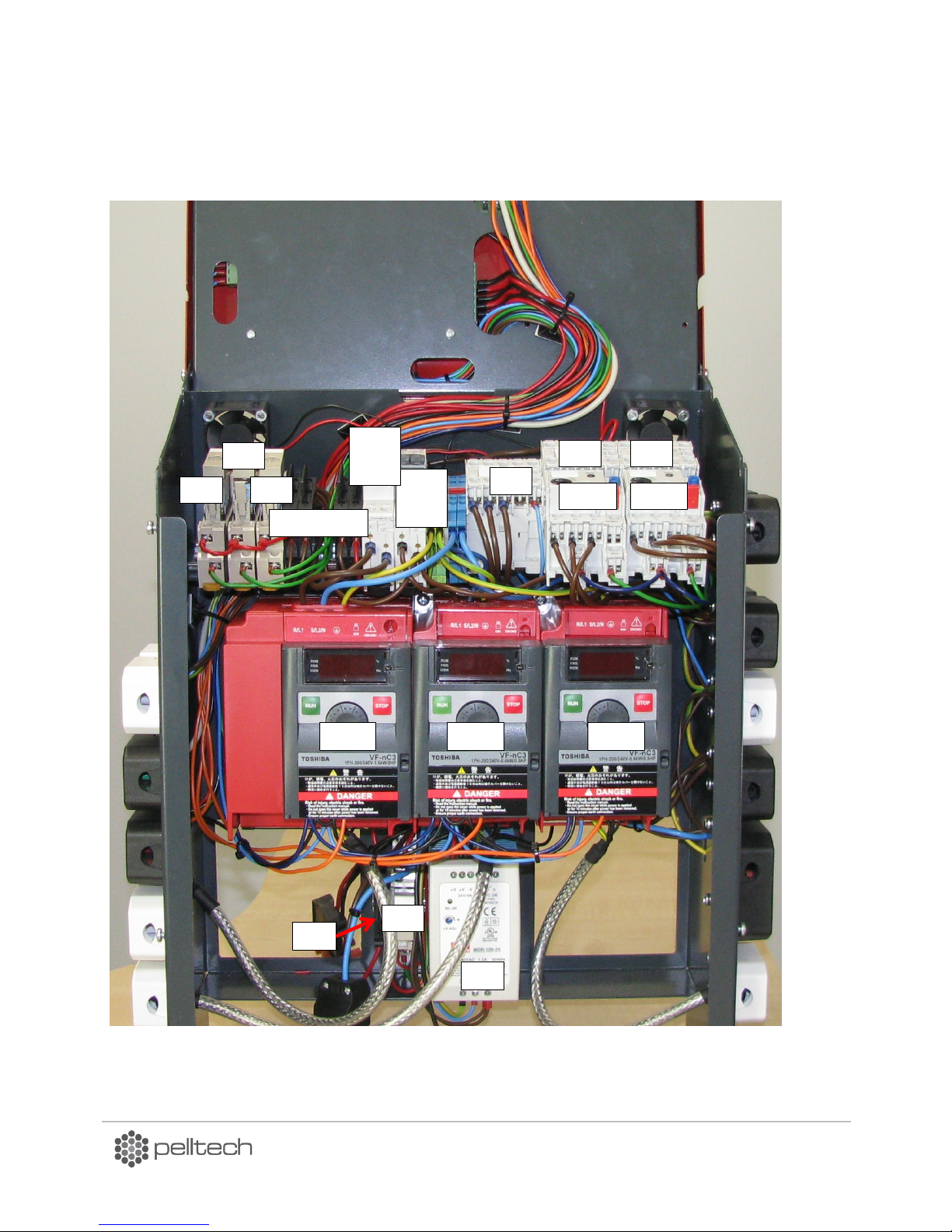
PV1000a pellet burner
p 52/ 58
T1
INV1
INV2
INV3
K3
K4
MF3
MF4
K5
QF4
QF3
QF1
QF2
K1
K7
F20, 21, 22, 23
K6
K8
F6
Figure 42 PV1000 contrtol unit
9 Annex 3 Control unit
DK9401B1 www.pelltech.eu
Page 54
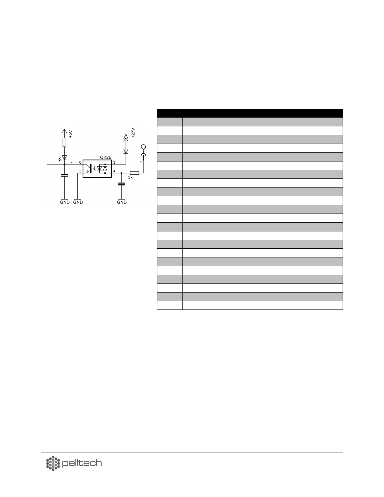
PV1000a pellet burner
p 53/ 58
Abr.
Description
INV1
Secondary fan’s inverter
INV2
Primary fan’s inverter
INV3
Flue gas fan (optional)
K1
Main power supply 3-pole contactor
K3
External auger 1 3-pole contactor
K4
External auger 2 3-pole contactor
MF3
External auger 1 3-pole motor protector
MF4
External auger 2 3-pole motor protector
K5
Igniters’ contactor
K6
Battery on/off contactor
K7
Ash auger contactor
K8
Fault circuit
QF1
Igniters’ 1-pole thermo-magnetic protector switch
QF2
INV3 L1 1-pole thermo-magnetic protector switch
QF3
INV2 L1 1-pole thermo-magnetic protector switch
QF4
INV1 L1 1-pole thermo-magnetic protector switch
T1
Power supply 230VAC/27,2VDC
F6
Battery’s fuse 6A
F20
Ash auger’s motor fuse 3A
F21
Ash scraper’s motor fuse0,25A
F22
Control voltage X11 fuse1 A
F23
Cooling fan’s motor fuse 1 A
Figure 43 DC input circuit
Table 24 Names of components on Figure 40
DK9401B1 www.pelltech.eu
Page 55
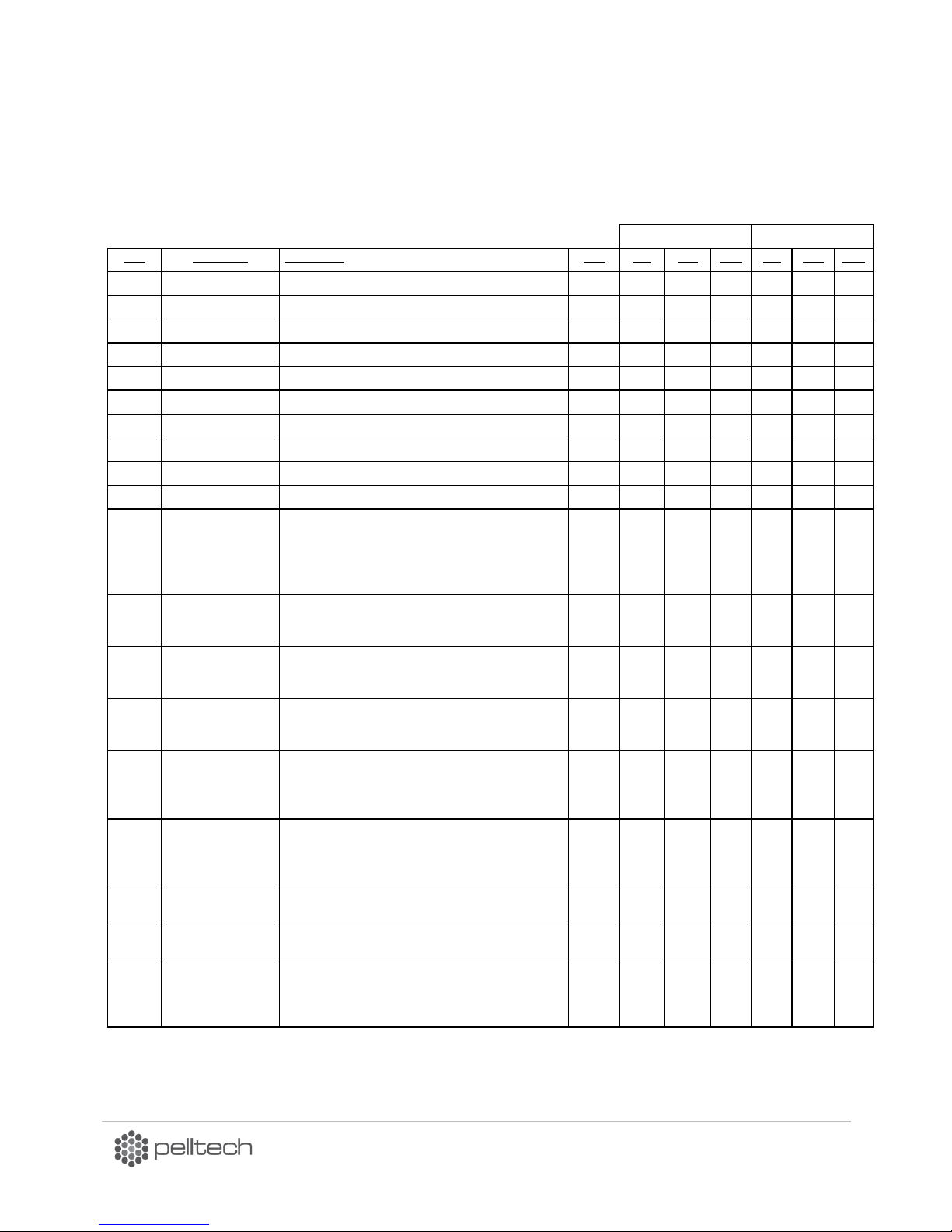
PV1000a pellet burner
p 54/ 58
Firmware version:
bbb: 2.08 22/11/13
PV700a
PV1000a
PAR
PAR Name
Description
Unit
Def
Min
Max
Def
Min
Max
PAR1
FAN@200(250)
Fan speed at 1.power level PV700(PV1000)
rps
28
15
50
24
15
50
PAR2
FAN@300(400)
Fan speed at 2.power level PV700(PV1000)
rps
32
15
50
30
15
50
PAR3
FAN@400(550)
Fan speed at 3.power level PV700(PV1000)
rps
34
15
50
34
15
50
PAR4
FAN@500(700)
Fan speed at 4.power level PV700(PV1000)
rps
37
15
50
38
15
50
PAR5
FAN@600(850)
Fan speed at 5.power level PV700(PV1000)
rps
40
15
50
42
15
50
PAR6
FAN@700(1000)
Fan speed at 6.power level PV700(PV1000)
rps
42
15
50
45
15
55
PAR7
FAN START
Fan speed at TESTING
%
170
80
240
170
80
240
PAR8
FAN@IGNITING
Fan speed at IGNITING and PRE-BURN
rps
20
15
35
20
15
35
PAR9
FAN@END BURN
Fan speed at END BURN
rps
20
10
40
20
10
40
PAR10
FAN@HOLD FLAME
Fan speed at HOLD FLAME
rps
10 7 14
10 7 14
PAR11
HOLD FLAME ON
If HOLD FLAME is set to ON in main menu then this
function starts at any case. If HOLD FLAME is set to
AUTO in main menu, then this function starts if time
set with this parameter is shorter than 2 sequential
WAITING times.
min
15 5 30
15 5 30
PAR12
HOLD FLAME OFF
Max time when burner holds flame. HOLD FLAME
function in main menu has to be set to AUTO or ON.
min
60
30
90
60
30
90
PAR13
MIN POWER
Minimum power level up to what burner decreases
output power. Applies if POWER in main menu is in
AUTO status only
kW
200
200
700
250
250
1000
PAR14
MAX POWER
Maximum power level up to what burner decreases
output power. Applies if POWER in main menu is set to
AUTO only
kW
700
200
700
1000
250
1000
PAR15
POWER UP
Timeframe to burner to increase power to one level up
if BURNING state lasts longer than set with this
parameter. Applies if POWER in main menu is set to
AUTO only
min
15 5 120
15 5 120
PAR16
POWER DOWN
Timeframe to burner to decrease power to one level
up if BURNING state lasts longer than set with this
parameter. Applies if POWER in main menu is set to
AUTO only
min
30
15
45
30
15
45
PAR17
UP CYCLE
Pace of increasing targeted power level part-steps
min 2 1 3 2 1 3
PAR18
DOWN CYCLE
Pace of decreasing targeted power level part-steps
min 2 1 3 2 1 3
PAR21
PELLETS NORMAL
Determines how many grams of pellets feeder auger
transports to burning chamber with one full rotation
when PELLET NORM ie normal weight pellets are
selected
g/rot
160
120
250
160
120
250
10 Annex 4 Table of parameters
DK9401B1 www.pelltech.eu
Page 56

PV1000a pellet burner
p 55/ 58
PAR22
PELLETS LIGHT
Determines how many grams of pellets feeder auger
transports to burning chamber with one full rotation
when PELLET LIGHT ie lighter than normal weight
pellets are selected
g/rot
150
120
250
150
120
250
PAR23
PELLETS HEAVY
Determines how many grams of pellets feeder auger
transports to burning chamber with one full rotation
when PELLET HEAVY ie heavier than normal weight
pellets are selected
g/rot
170
120
250
170
120
250
PAR24
LOADING FEED
Number of feeder auger rotations in LOADING state
rot
40
20
80
40
20
80
PAR25
LOADING 2 FEED
Number of feeder auger rotations in LOADING2 state
rot 5 1
15 5 1
15
PAR26
END BURN FEED
Number of feeder auger rotations in END BURN state
rot
70
40
120
80
20
120
PAR27
END BLOW TIME
Fan's END BLOW time after flame has disappeared
sec 2 1
15 2 1
15
PAR30
FAN 2
Secondary fan On//OFF control (not used in PV50b)
1/2 3 1 3 3 1 3
PAR31
FAN 2@200(250)
Secondary fan speed at 1.power level PV700(PV1000)
rps
13 5 80
16 5 40
PAR32
FAN 2@300(400)
Secondary fan speed at 2.power level PV700(PV1000)
rps
23 5 80
22 5 50
PAR33
FAN 2@400(550)
Secondary fan speed at 3.power level PV700(PV1000)
rps
32 5 80
30 5 55
PAR34
FAN 2@500(700)
Secondary fan speed at 4.power level PV700(PV1000)
rps
39 5 80
38 5 55
PAR35
FAN 2@600(850)
Secondary fan speed at 5.power level PV700(PV1000)
rps
41 5 80
42 5 55
PAR36
FAN 2@700(1000)
Secondary fan speed at 6.power level PV700(PV1000)
rps
43 5 80
46 5 55
PAR38
FAN 2 BASE
Changing amount of secondary fan base air with flue
gas fan speed setting in all power levels
%
100
65
140
100
65
140
PAR39
FAN 2 MIN
Secondary fan minimal speed
rps 7 5
20 7 5
20
PAR40
PHOTOCELL LEVEL
Flame sensor sensitivity. Higher number means that
flame is recognized when less light
%
90
50
100
90
50
100
PAR41
PRE-BURN TIME
Length of one PRE-BURN cycle state
sec
25
15
80
25
15
80
PAR42
PRE-BURN CYCLES
Number of PRE-BURN cycles. Total length of PRE-BURN
cycles is length of one cycle times number of cycles
X 6 2
10 6 2
10
PAR46
FEED CURRENT
Preset feeder auger motors current. Overcurrent
protection threshold
A 6 1
9,9 6 1
9,9
PAR47
GRATES CURRENT
Grate motor overcurrent protection threshold
A 2 0,2 6 2
0,2
6
PAR48
CLEANING CYCLE
Pre-set time between two cleaning cycles 0=CLEANING
OFF
min
30 0 250
30 0 250
PAR50
RELAY ERROR
ERR output function selection
1/2 1 1 2 1 1 2
PAR52
SMS COUNT
Selecting number of phones receiving alert SMS
X 1 0 5 1 0 5
PAR53
TEMP.TYPE
Determines temperature sensor type plugged in TMP1
connector
- 0 0
10 0 0
10
PAR54
TEMP.LEVEL
Set point value for temperature sensor plugged to
TMP1
°C
70
30
200
70
30
200
PAR55
TEMP.HYST
PAR54 maximum set point hysteresis
°C 5 2
10 5 2
10
DK9401B1 www.pelltech.eu
Page 57
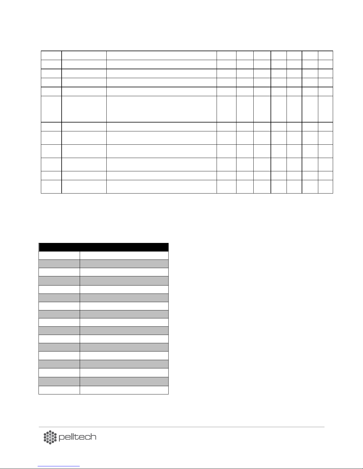
PV1000a pellet burner
p 56/ 58
PAR58
BASE FREQUENCY
Grid frequency
Hz
50
45
63
50
45
63
PAR60
FLUE GAS TYPE
Flue gas fan ON-OFF turning 0 OFF 2 ON
- 2 0 2 2 0 2
PAR61
DRAFT SET
Flue gas fan pre-set pressure set point
-Pa 8 0
250 8 0
250
PAR62
DRAFT ERROR
Draught error threshold value
+Pa
10 0 20
10 0 20
PAR63
DRAFT BASE
Draught sensor calibration value
%
110
50
150
110
50
150
PAR66
OXYGEN TYPE
Type of oxygene sensor:
0 no sensor;
1 4..20mA=0..25%;
2 4..20mA=0..20%
- 0 0 2 0 0 2
PAR67
OXYGEN SET
Oxygen level setpoint
% 6 4
14 6 4
14
PAR70
HEAT UP TIME
Initial heat up time for burners with ceramic burning
chamber
min
20 0 60
20 0 60
PAR71
HEAT UO POWER
Initial heat up power for burners with ceramic burning
chamber
kW 5 1
10 7 1
15
PAR72
HEAT UP TEMP.
Initial heat up temperature for burners with ceramic
burning chamber
-
50
25
90
50
25
90
PAR73
TEMP BASE
TEMP BASE
-
20 0 100
20 0 100
PAR99
BURNER TYPE
Selecting model of burner. Software of wrongly
selected model works incorrectly
-
700
20
1M
1M
20
1M
Language
ENG
English
SPA
Spanish
EST
Estonian
FIN
Finnish
FRA
France
GER
Germany
GRE
Greece
HRV
Croatian
LIT
Lithuanian
LAT
Latvian
NED
Dutch
POR
Portuguese
RUS
Russian
SLO
Slovenian
SRB
Serbian
SVK
Slovakian
SWE
Swedish
11 Annex 5 Table of languages
DK9401B1 www.pelltech.eu
Page 58

Warranty
Warranty objects in this context are pellet burner PV700 or PV1000 and supplied auger.
Producer gives 2 years warranty from the date of sale for the PV 700 or PV 1000 burner and supplied
auger.
Exception is ignition element (igniter), for this item warranty is 1 (one) year.
Warranty is valid when user had not made changes in the construction and setup of the burner.
Warranty does not cover defects caused by an accident, misuse, abuse, improper installation or
operation, lack of reasonable care, unauthorized medication, loss of parts, tampering, attempted repair
by a not authorized person, mains errors or using poor quality fuel.
Warranty is valid only if the bottom half of the warranty ticket is filled in and sent or brought to the
office of Pelltech OÜ Sära tee 3, Peetri, Rae vald, 75312 Harjumaa ESTONIA
Ph.. + 372 677 5277
www.pelletikeskus.ee
Page 59

Burners model
PV700 or PV1000
Product number
…………………………………………………….
Sales date
…………………………………………………….
Installation/commissioning date
…………………………………………………….
Owners contacts
Installers name and signature
Name …………………………………………………….
…………………………………………………….
Phone nr ……………………………………………………
…………………………………………………….
City/village ……………………………………………………
Street/ House ……………………………………………………
Burners model
PV700 or PV1000
Product number
…………………………………………………….
Sales date
…………………………………………………….
Installation/commissioning date
…………………………………………………….
Owners contacts
Installers name and signature
Name …………………………………………………….
…………………………………………………….
Phone nr ……………………………………………………
…………………………………………………….
City/village ……………………………………………………
Street/ House ……………………………………………………
Warranty is valid only if the bottom half of the warranty ticket is filled in and sent or brought to the office
of Pelltech OÜ Sära tee 3, Peetri, Rae vald, 75312 Harjumaa ESTONIA
Ph.. + 372 677 5277
www.pelletikeskus.ee
Warranty ticket
...................................................................Cut here!...................................................................................
Warranty ticket
 Loading...